EP1989087B1 - Method and device for controlling the traction slip of the driven wheels of a vehicle with the engine torque as a set parameter - Google Patents
Method and device for controlling the traction slip of the driven wheels of a vehicle with the engine torque as a set parameter Download PDFInfo
- Publication number
- EP1989087B1 EP1989087B1 EP07722843A EP07722843A EP1989087B1 EP 1989087 B1 EP1989087 B1 EP 1989087B1 EP 07722843 A EP07722843 A EP 07722843A EP 07722843 A EP07722843 A EP 07722843A EP 1989087 B1 EP1989087 B1 EP 1989087B1
- Authority
- EP
- European Patent Office
- Prior art keywords
- speed
- instantaneous
- control unit
- vehicle
- upper limit
- Prior art date
- Legal status (The legal status is an assumption and is not a legal conclusion. Google has not performed a legal analysis and makes no representation as to the accuracy of the status listed.)
- Active
Links
- 238000000034 method Methods 0.000 title claims description 10
- 230000005540 biological transmission Effects 0.000 claims description 9
- 238000001514 detection method Methods 0.000 claims 2
- 230000001133 acceleration Effects 0.000 description 2
- 238000002485 combustion reaction Methods 0.000 description 2
- 238000012935 Averaging Methods 0.000 description 1
- 230000001419 dependent effect Effects 0.000 description 1
- 238000002347 injection Methods 0.000 description 1
- 239000007924 injection Substances 0.000 description 1
- 230000003068 static effect Effects 0.000 description 1
Images

Classifications
-
- B—PERFORMING OPERATIONS; TRANSPORTING
- B60—VEHICLES IN GENERAL
- B60T—VEHICLE BRAKE CONTROL SYSTEMS OR PARTS THEREOF; BRAKE CONTROL SYSTEMS OR PARTS THEREOF, IN GENERAL; ARRANGEMENT OF BRAKING ELEMENTS ON VEHICLES IN GENERAL; PORTABLE DEVICES FOR PREVENTING UNWANTED MOVEMENT OF VEHICLES; VEHICLE MODIFICATIONS TO FACILITATE COOLING OF BRAKES
- B60T8/00—Arrangements for adjusting wheel-braking force to meet varying vehicular or ground-surface conditions, e.g. limiting or varying distribution of braking force
- B60T8/17—Using electrical or electronic regulation means to control braking
- B60T8/175—Brake regulation specially adapted to prevent excessive wheel spin during vehicle acceleration, e.g. for traction control
-
- B—PERFORMING OPERATIONS; TRANSPORTING
- B60—VEHICLES IN GENERAL
- B60K—ARRANGEMENT OR MOUNTING OF PROPULSION UNITS OR OF TRANSMISSIONS IN VEHICLES; ARRANGEMENT OR MOUNTING OF PLURAL DIVERSE PRIME-MOVERS IN VEHICLES; AUXILIARY DRIVES FOR VEHICLES; INSTRUMENTATION OR DASHBOARDS FOR VEHICLES; ARRANGEMENTS IN CONNECTION WITH COOLING, AIR INTAKE, GAS EXHAUST OR FUEL SUPPLY OF PROPULSION UNITS IN VEHICLES
- B60K28/00—Safety devices for propulsion-unit control, specially adapted for, or arranged in, vehicles, e.g. preventing fuel supply or ignition in the event of potentially dangerous conditions
- B60K28/10—Safety devices for propulsion-unit control, specially adapted for, or arranged in, vehicles, e.g. preventing fuel supply or ignition in the event of potentially dangerous conditions responsive to conditions relating to the vehicle
- B60K28/16—Safety devices for propulsion-unit control, specially adapted for, or arranged in, vehicles, e.g. preventing fuel supply or ignition in the event of potentially dangerous conditions responsive to conditions relating to the vehicle responsive to, or preventing, skidding of wheels
-
- B—PERFORMING OPERATIONS; TRANSPORTING
- B60—VEHICLES IN GENERAL
- B60T—VEHICLE BRAKE CONTROL SYSTEMS OR PARTS THEREOF; BRAKE CONTROL SYSTEMS OR PARTS THEREOF, IN GENERAL; ARRANGEMENT OF BRAKING ELEMENTS ON VEHICLES IN GENERAL; PORTABLE DEVICES FOR PREVENTING UNWANTED MOVEMENT OF VEHICLES; VEHICLE MODIFICATIONS TO FACILITATE COOLING OF BRAKES
- B60T2270/00—Further aspects of brake control systems not otherwise provided for
- B60T2270/20—ASR control systems
- B60T2270/211—Setting or adjusting start-control threshold
-
- B—PERFORMING OPERATIONS; TRANSPORTING
- B60—VEHICLES IN GENERAL
- B60W—CONJOINT CONTROL OF VEHICLE SUB-UNITS OF DIFFERENT TYPE OR DIFFERENT FUNCTION; CONTROL SYSTEMS SPECIALLY ADAPTED FOR HYBRID VEHICLES; ROAD VEHICLE DRIVE CONTROL SYSTEMS FOR PURPOSES NOT RELATED TO THE CONTROL OF A PARTICULAR SUB-UNIT
- B60W2510/00—Input parameters relating to a particular sub-units
- B60W2510/06—Combustion engines, Gas turbines
- B60W2510/0638—Engine speed
-
- B—PERFORMING OPERATIONS; TRANSPORTING
- B60—VEHICLES IN GENERAL
- B60W—CONJOINT CONTROL OF VEHICLE SUB-UNITS OF DIFFERENT TYPE OR DIFFERENT FUNCTION; CONTROL SYSTEMS SPECIALLY ADAPTED FOR HYBRID VEHICLES; ROAD VEHICLE DRIVE CONTROL SYSTEMS FOR PURPOSES NOT RELATED TO THE CONTROL OF A PARTICULAR SUB-UNIT
- B60W2520/00—Input parameters relating to overall vehicle dynamics
- B60W2520/28—Wheel speed
-
- B—PERFORMING OPERATIONS; TRANSPORTING
- B60—VEHICLES IN GENERAL
- B60W—CONJOINT CONTROL OF VEHICLE SUB-UNITS OF DIFFERENT TYPE OR DIFFERENT FUNCTION; CONTROL SYSTEMS SPECIALLY ADAPTED FOR HYBRID VEHICLES; ROAD VEHICLE DRIVE CONTROL SYSTEMS FOR PURPOSES NOT RELATED TO THE CONTROL OF A PARTICULAR SUB-UNIT
- B60W2540/00—Input parameters relating to occupants
- B60W2540/16—Ratio selector position
-
- B—PERFORMING OPERATIONS; TRANSPORTING
- B60—VEHICLES IN GENERAL
- B60W—CONJOINT CONTROL OF VEHICLE SUB-UNITS OF DIFFERENT TYPE OR DIFFERENT FUNCTION; CONTROL SYSTEMS SPECIALLY ADAPTED FOR HYBRID VEHICLES; ROAD VEHICLE DRIVE CONTROL SYSTEMS FOR PURPOSES NOT RELATED TO THE CONTROL OF A PARTICULAR SUB-UNIT
- B60W2710/00—Output or target parameters relating to a particular sub-units
- B60W2710/06—Combustion engines, Gas turbines
- B60W2710/0644—Engine speed
Definitions
- the invention is based on a method and a device for controlling the drive slip of driven wheels of a vehicle, according to the preambles of claims 1 and 3.
- ABS Electronic brake systems
- Fig.1 schematically shows the structure of a control loop 10 for the control of the drive torque of a drive motor 12 of a commercial vehicle.
- the wheel speeds of the driven wheels present on a drive train 14 are measured via wheel speed sensors and corresponding signals are fed into a brake control unit 16 with integrated functional part for traction control ASR.
- This brake control unit 16 is, for example, via a CAN interface 18 to SAE J1939 with an engine control unit 20, which drives the drive motor 12. Via the interface 18, the brake control unit 16 can then deliver a desired value for the drive torque of the drive motor 12 to the engine control unit 20.
- Fig.2 shows the basic structure of the control structure of the engine torque control within the traction control system.
- a setpoint value for the wheel speed is calculated from the momentary wheel speed of a driven wheel, the instantaneous vehicle speed and a permissible drive slip. This setpoint is compared with the actual value of the current wheel speed and the speed control deviation determined.
- the brake control unit 16 calculates the setpoint value for the drive torque of the drive motor 12 with an electronic controller.
- the essential feature of this control therefore, is that the control variable calculated by the controller engages
- Target drive torque for the drive motor 12 is used as inputs but the wheel speeds of the driven wheels. Since further control loops are subordinate, which influence the drive torque of the drive motor 12, this setpoint specification in the engine control unit 20 is often not implemented identically.
- Purpose of in the WO 01/28802 described method is to avoid damage to differential gears or tires by excessive speed differences between the driven wheels of an axle.
- an essential difference is that with the known method the relative traction slip (wheel speed difference between the wheels of the front axle and the rear axle) between driven wheels of a vehicle is to be limited to a predetermined value while In traction control systems, however, the absolute drive slip of the driven wheels, ie the slip between the wheel and the road is adjusted to an optimum value in order to start or accelerate with the best adhesion between the wheel and the road.
- the present invention is therefore based on the object, such a method and an apparatus of the type mentioned in such a way that an engine speed control for traction control is easy to implement and works exactly.
- the invention uses an upper limit speed of the drive motor instead of the desired drive torque as an actuating variable.
- Upper limit speed means that the vehicle is operated up to this limit speed in the stable range of the traction slip curve or in the frictional maximum, while at above the upper limit speed beyond the unstable range of the power circuit slip curve is achieved.
- the upper limit speed represents a speed setpoint of the drive motor.
- the engine speed controller implemented in each engine control unit can adjust a speed specification much faster and more accurately than is possible by a drive torque specification.
- the invention thus avoids the detour via the control of the drive torque as a manipulated variable in the traction control system, whereby a controller and the necessary for this controller application costs for tuning the controller response to the vehicle or the drive motor deleted.
- a controller and the necessary for this controller application costs for tuning the controller response to the vehicle or the drive motor deleted.
- the speed controller which is already present in engine control units and tuned to the respective drive motor can be used. This results in a simpler structure and an improved control behavior.
- a mutual influence of different, on the drive torque as a control variable acting regulator avoided.
- the current gear ratio is calculated. Then, the upper limit value for the rotational speed of the drive motor can be calculated from the target wheel speed and the current transmission ratio.
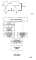
- FIG. 3 shows Figure 3 the basic structure of the control structure of an engine speed control within a traction control system according to a preferred embodiment of the invention.
- control circuit 10 for controlling the drive torque is in principle valid for a traction control ASR according to the invention by means of engine speed control, with the difference that according to the invention as a control variable of the control loop 10 not the drive torque of the drive motor 12, but a permissible upper limit speed of the drive motor 12 dependent is used by the present on the respective drive wheel or on a plurality of drive wheels slip.
- the traction control system is realized within an electronic brake system of a commercial vehicle and, in addition to the drive motor 12, also influences its brake system. Since the latter function is not essential to the invention, will not be discussed in the following.
- the drive motor 12 acts on the drive train 14, which consists for example of a transmission, a cardan shaft, a transfer case, the respective drive shafts and the driven wheels associated with a driven axle.
- the commercial vehicle can be driven on one as well as on two axles.
- the driven and non-driven wheels are associated with wheel speed sensors which control signals for the current wheel speed in the brake control unit 16, in which run, for example, routines for an additional existing ABS control and / or for an electronic stability program (ESP).
- ESP electronic stability program
- the brake control unit 16 is provided with an integrated functional part for traction control, which is connected, for example via a CAN interface 18 to SAE J1939 with the engine control unit 20.
- the latter in turn controls the power, torque and speed of the drive motor 12 and in particular includes an engine speed controller which is present anyway for other tasks.
- Figure 3 shows the basic structure of the control structure of the engine speed control, wherein the current wheel speed present at the respective drive wheel represents the input, which is detected according to function block 1 of the wheel speed sensors. Furthermore, the instantaneous engine speed is measured in a known manner.
- blocks 2 to 4 are already known from the prior art and relate to the calculation of the instantaneous vehicle speed in block 2, for example from the signals of the wheel speed sensors of non-driven axles. From this size and the wheel speeds of the driven wheels then the instantaneous slip of the drive wheels can be calculated during an acceleration process.
- the permissible or optimal drive slip is determined, for example, from stored traction slip characteristics, from which the desired wheel speeds of the driven wheels according to block 4 result.
- n_mot_max v_cmd * i_total
- n_mot_max consequently forms the speed setpoint for the engine speed controller integrated in the engine control unit 20 and is transmitted via the CAN interface 18.
- the control deviation between the upper limit n_mot_max and the actual engine speed is calculated by the speed controller 20.
- the speed setpoint value is then adjusted, for example, by a regulator acting on the throttle valve and in a self-igniting internal combustion engine by a controller acting on the diesel injection pump, with the respective actuator being controlled by the speed controller 20.
Landscapes
- Engineering & Computer Science (AREA)
- Chemical & Material Sciences (AREA)
- Combustion & Propulsion (AREA)
- Transportation (AREA)
- Mechanical Engineering (AREA)
- Control Of Vehicle Engines Or Engines For Specific Uses (AREA)
- Regulating Braking Force (AREA)
- Electric Propulsion And Braking For Vehicles (AREA)
- Combined Controls Of Internal Combustion Engines (AREA)
- Control Of Driving Devices And Active Controlling Of Vehicle (AREA)
Abstract
Description
Die Erfindung geht aus von einem Verfahren und von einer Vorrichtung zur Regelung des Antriebsschlupfes angetriebener Räder eines Fahrzeugs, gemäß den Oberbegriffen der Ansprüche 1 und 3.The invention is based on a method and a device for controlling the drive slip of driven wheels of a vehicle, according to the preambles of
Beim Anfahren oder Beschleunigen hängt die Kraftübertragung vom Schlupf zwischen Reifen und Fahrbahn ab. Diese Abhängigkeit kann in Kraftschluss-Schlupfkurven dargestellt werden. Bei kleinen Schlupfwerten-laufen die Beschleunigungsvorgänge im stabilen Bereich ab, erhöht sich der Schlupf, nimmt auch der nutzbare Kraftschluss, d.h. die Haftreibungszahl zu. Mit zunehmendem Schlupf über das erreichbare Kraftschlussmaximum hinaus wird der instabile Bereich der Schlupfkurve erreicht, weil eine weitere Erhöhung des Schlupfes zu einer Reduzierung des Kraftschlusses führt.When starting or accelerating the power transmission depends on the slip between the tire and the road. This dependence can be represented in traction slip curves. With small slip values, the acceleration processes in the stable range are reduced, the slip increases, and the usable frictional connection, i.e., the slip increases. the static friction coefficient too. With increasing slip beyond the achievable traction maximum, the unstable region of the slip curve is achieved, because a further increase in slip leads to a reduction of the frictional connection.
Zur Anpassung des Antriebsschlupfes an zulässige Werte werden Antriebsschlupfregelungen (ASR) eingesetzt, welche zum einen das Antriebsmoment des Antriebsmotors regeln und zusätzlich die Bremsanlage des Fahrzeugs aktivieren. Elektronische Bremssysteme (EBS) von modernen Nutzfahrzeugen, in welche auch ABS-Systeme integriert sind, haben deshalb Bremssteuergeräte mit einem Funktionsteil zur Antriebsschlupfregelung.To adapt the traction slip to allowable values traction control systems (ASR) are used, which on the one hand regulate the drive torque of the drive motor and also activate the brake system of the vehicle. Electronic brake systems (EBS) of modern commercial vehicles, in which also ABS systems are integrated, therefore have brake control devices with a functional part for traction control.
Sollantriebsmoment für den Antriebsmotor 12 ist, als Eingangsgrößen jedoch die Radgeschwindigkeiten der angetriebenen Räder verwendet werden. Da weitere Regelkreise unterlagert sind, welche das Antriebsmoment des Antriebsmotors 12 beeinflussen, wird diese Sollwertvorgabe im Motorsteuergerät 20 jedoch oft nicht identisch umgesetzt.Target drive torque for the drive motor 12 is used as inputs but the wheel speeds of the driven wheels. Since further control loops are subordinate, which influence the drive torque of the drive motor 12, this setpoint specification in the
In der gattungsbildenden
Zweck des in der
Der vorliegenden Erfindung liegt daher die Aufgabe zugrunde, ein Verfahren und eine Vorrichtung der eingangs erwähnten Art derart weiter zu entwickeln, dass eine Motordrehzahlregelung zur Antriebsschlupfregelung einfach zu realisieren ist und genau arbeitet.The present invention is therefore based on the object, such a method and an apparatus of the type mentioned in such a way that an engine speed control for traction control is easy to implement and works exactly.
Diese Aufgabe wird erfindungsgemäß durch die Merkmale von Anspruch 1 und Anspruch 3 gelöst.This object is achieved by the features of
Da Antriebsschlupfregelungen (ASR) einen Schlupf und damit Raddrehzahlen regeln und diese Raddrehzahlen proportional zur Drehzahl des Antriebsmotors sind, verwendet die Erfindung anstatt des Sollantriebsmoments eine obere Grenzdrehzahl des Antriebsmotors als stellgröße. Obere Grenzdrehzahl bedeutet dabei, dass das Fahrzeug bis zu dieser Grenzdrehzahl im stabilen Bereich der Kraftschluss-Schlupfkurve bzw. im Kraftschlussmaximum betrieben wird, während bei über die obere Grenzdrehzahl hinausgehenden Drehzahlen der instabile Bereich der Kräftschluss-Schlupfkurve erreicht wird. Insofern stellt die obere Grenzdrehzahl einen Drehzahlsollwert des Antriebsmotors dar.Since traction control systems (ASR) regulate slip and thus wheel speeds and these wheel speeds are proportional to the speed of the drive motor, the invention uses an upper limit speed of the drive motor instead of the desired drive torque as an actuating variable. Upper limit speed means that the vehicle is operated up to this limit speed in the stable range of the traction slip curve or in the frictional maximum, while at above the upper limit speed beyond the unstable range of the power circuit slip curve is achieved. In this respect, the upper limit speed represents a speed setpoint of the drive motor.
Der in jedem Motorsteuergerät implementierte Motordrehzahlregler kann eine Drehzahlvorgabe wesentlich schneller und genauer einregeln als durch eine Antriebsmomentvorgabe möglich ist. Die Erfindung vermeidet folglich bei der Antriebsschlupfregelung den Umweg über die Regelung des Antriebsmoments als Stellgröße, wodurch ein Regler und der für diesen Regler notwendige Applikationsaufwand zur Abstimmung des Reglerverhaltens auf das Fahrzeug bzw. den Antriebsmotor entfällt. Zur Regelung des Antriebsschlupfes kann hingegen ausschließlich der in Motorsteuergeräten ohnehin vorhandene und auf den jeweiligen Antriebsmotor abgestimmte Drehzahlregler verwendet werden. Dadurch ergibt sich eine einfachere Struktur und ein verbessertes Regelverhalten. Weiterhin wird eine gegenseitige Beeinflussung verschiedener, auf das Antriebsmoment als Stellgröße wirkender Regler vermieden. Nicht zuletzt kann der Datentransfer zur Übertragung des Signals für die maximal zulässige Motordrehzahl zwischen dem Bremssteuergerät und dem Motorsteuergerät über die bereits eingangs erwähnte CAN-Schnittstelle nach SAE J1939 erfolgen.The engine speed controller implemented in each engine control unit can adjust a speed specification much faster and more accurately than is possible by a drive torque specification. The invention thus avoids the detour via the control of the drive torque as a manipulated variable in the traction control system, whereby a controller and the necessary for this controller application costs for tuning the controller response to the vehicle or the drive motor deleted. For controlling the traction slip, however, only the speed controller which is already present in engine control units and tuned to the respective drive motor can be used. This results in a simpler structure and an improved control behavior. Furthermore, a mutual influence of different, on the drive torque as a control variable acting regulator avoided. Last but not least, the data transfer to transmit the signal for the maximum engine speed between the brake control unit and the engine control unit via the already mentioned above CAN interface to SAE J1939 done.
Zunächst wird basierend auf der momentanen Drehzahl des Antriebsmotors und der momentanen Radgeschwindigkeit das momentane Übersetzungsverhältnis berechnet. Sodann kann der obere Grenzwert für die Drehzahl des Antriebsmotors aus der Radsollgeschwindigkeit und dem momentanen Übersetzungsverhältnis berechnet werden.First, based on the current speed of the drive motor and the current wheel speed, the current gear ratio is calculated. Then, the upper limit value for the rotational speed of the drive motor can be calculated from the target wheel speed and the current transmission ratio.
Genaueres geht aus der folgenden Beschreibung eines Ausführungsbeispiels hervor.More specifically, it will be apparent from the following description of an embodiment.
Nachstehend ist ein Ausführungsbeispiel der Erfindung in der Zeichnung dargestellt und in der nachfolgenden Beschreibung näher erläutert. In der Zeichnung zeigt
Der in
Im einzelnen wirkt der Antriebsmotor 12 auf den Antriebsstrang 14, welcher beispielsweise aus einem Getriebe, einer Kardanwelle, einem Verteilergetriebe, den jeweiligen Antriebswellen und den einer angetriebenen Achse zugeordneten Antriebsrädern besteht. Dabei kann das Nutzfahrzeug an einer wie auch an zwei Achsen angetrieben sein. Den angetriebenen und nicht angetriebenen Rädern sind Radgeschwindigkeitssensoren zugeordnet, welche Signale für die momentane Radgeschwindigkeit in das Bremssteuergerät 16 einsteuern, in welchem beispielsweise auch Routinen für eine zusätzlich vorhandene ABS-Regelung und/oder für ein elektronisches Stabilitätsprogramm (ESP) ablaufen.Specifically, the drive motor 12 acts on the
Darüber hinaus ist das Bremssteuergerät 16 mit einem integriertem Funktionsteil zur Antriebsschlupfregelung versehen, welches beispielsweise über eine CAN-Schnittstelle 18 nach SAE J1939 mit dem Motorsteuergerät 20 verbunden ist. Letzteres steuert wiederum Leistung, Drehmoment und Drehzahl des Antriebsmotors 12 und beinhaltet insbesondere einen für andere Aufgaben ohnehin vorhandenen Motordrehzahlregler.In addition, the
Im Funktionsblock 5 wird aus den Radgeschwindigkeiten der Antriebsräder und der aktuellen Motordrehzahl dann das momentane Übersetzungsverhältnis i_total wie folgt berechnet : 
wobei
- n_mot:
- die momentane Motordrehzahl,
- v_2r, v_2l
- die momentanen Radgeschwindigkeiten der Antriebsräder einer angetriebenen Achse sind.
in which
- n_mot:
- the instantaneous engine speed,
- v_2r, v_2l
- the instantaneous wheel speeds of the driven wheels of a driven axle.
Diese Art der Berechnung über eine Mittelwertbildung ist auch auf mehrere angetriebene Achsen übertragbar. Bei einem Nutzfahrzeug mit zwei angetriebenen Achsen oder vier angetriebenen Rädern gilt für das momentane Übersetzungsverhältnis i_total beispielsweise : ![]()
wobei
- n_mot :
- die momentane Motordrehzahl,
- v_2r, v_2l. v_3l, v_3r
- die momentanen Radgeschwindigkeiten der Antriebsräder zweier angetriebenen Achse sind.
in which
- n_mot:
- the instantaneous engine speed,
- v_2r, v_2l. v_3l, v_3r
- the instantaneous wheel speeds of the drive wheels of two driven axle.
Die in den Blöcken 2 bis 4 durchgeführten Funktionen sind bereits aus dem Stand der Technik bekannt und betreffen die Berechnung der momentanen Fahrzeuggeschwindigkeit in Block 2, beispielsweise aus den Signalen der Raddrehzahlsensoren nicht angetriebener Achsen. Aus dieser Größe und den Raddrehzahlen der angetriebenen Räder kann dann der momentane Schlupf der Antriebsräder während eines Beschleunigungsvorgangs berechnet werden. Gemäß Block 3 wird der zulässige oder optimale Antriebsschlupf beispielsweise aus gespeicherten Kraftschluss-Schlupfkennlinien ermittelt, woraus sich auch die Sollradgeschwindigkeiten der angetriebenen Räder gemäß Block 4 ergeben.The functions performed in
In Block 6 wird dann schließlich aus der in Block 4 berechneten Radsollgeschwindigkeit und dem in Block 5 berechneten Übersetzungsverhältnis i_total ein oberer Grenzwert n_mot_max für die Motordrehzahl wie folgt berechnet: ![]()
![]()
Würde der Antriebsmotor mit einer Drehzahl oberhalb des oberen Grenzwert n_mot_max betrieben, würde sich der Schlupf erhöhen und dadurch der Kraftschluss sinken, während ein Betrieb des Antriebsmotors mit demgegenüber geringeren Drehzahlen eine stabile Fahrt und mit dem oberen Grenzwert n_mot_max eine Fahrt im Kraftschlussmaximum ermöglicht. Der obere Grenzwert n_mot_max bildet folglich den Drehzahlsollwert für den im Motorsteuergerät 20 integrierten Motordrehzahlregler und wird über die CAN-Schnittstelle 18 übertragen.If the drive motor operated at a speed above the upper limit n_mot_max, the slip would increase and thus the adhesion decrease, while operating the drive motor with the other hand, lower speeds a stable ride and with the upper limit n_mot_max allows a ride in the traction maximum. The upper limit value n_mot_max consequently forms the speed setpoint for the engine speed controller integrated in the
Anschließend wird die Regelabweichung zwischen dem oberen Grenzwert n_mot_max und der Ist-Motordrehzahl vom Drehzahlregler 20 berechnet. Bei einer fremdgezündeten Brennkraftmaschine wird dann beispielsweise durch einen auf die Drosselklappe wirkenden Steller und bei einer selbstzündende Brennkraftmaschine durch einen auf die Dieseleinspritzpumpe wirkenden Steller der Drehzahlsollwert eingeregelt, wobei der jeweilige Steller vom Drehzahlregler 20 angesteuert wird.Subsequently, the control deviation between the upper limit n_mot_max and the actual engine speed is calculated by the
- 1010
- Regelkreisloop
- 1212
- Antriebsmotordrive motor
- 1414
- Antriebsstrangpowertrain
- 1616
- BremsteuergerätBrake control unit
- 1818
- Schnittstelleinterface
- 2020
- MotorsteuergerätEngine control unit
Claims (6)
- A method for controlling the traction slip of driven wheels of a vehicle between the wheels and the carriageway, in the case of which a manipulated variable is calculated for a drive engine (12) of the vehicle on the basis of a detection of the instantaneous wheel speed and the calculation of a desired wheel speed, the manipulated variable being formed by an upper limit value for the rotational speed of the drive engine (12), characterized in that the instantaneous transmission ratio is calculated on the basis of the instantaneous rotational speed of the drive engine (12) and the instantaneous wheel speed, and the upper limit value for the rotational speed of the drive engine (12) is calculated from the desired wheel speed and the instantaneous transmission ratio.
- The method as claimed in claim 1, characterized in that the desired wheel speed is calculated from the instantaneous vehicle speed and a permissible traction slip value.
- A device for controlling the traction slip of driven wheels of a vehicle, having at least one control unit (16) that calculates a manipulated variable for a drive engine (12) of the vehicle on the basis of a detection of the instantaneous wheel speed and calculation of a desired wheel speed, the manipulated variable being formed by an upper limit value for the rotational speed of the drive engine (12), characterized in that the at least one control unit (16) is designed in such a way that it calculates the instantaneous transmission ratio on the basis of the instantaneous rotational speed of the drive engine (12) and the instantaneous wheel speed, and calculates the upper limit value for the rotational speed of the drive engine (12) from the desired wheel speed and the instantaneous transmission ratio.
- The device as claimed in claim 3, characterized in that the at least one control unit (16) is a control unit of an electronic brake system (EBS) or of an antilock brake system (ABS).
- The device as claimed in claim 4, characterized in that an engine control unit (20) has a rotational speed controller that regulates the drive engine (12) to the upper limit value for the rotational speed.
- The device as claimed in claim 4 and 5, characterized in that the upper limit value for the rotational speed is fed into the engine control unit by the control unit (16) via a CAN interface (18).
Applications Claiming Priority (2)
| Application Number | Priority Date | Filing Date | Title |
|---|---|---|---|
| DE102006007740.7A DE102006007740B4 (en) | 2006-02-20 | 2006-02-20 | Method and device for controlling the traction slip of driven wheels of a vehicle with the engine speed as the manipulated variable |
| PCT/EP2007/001403 WO2007096110A1 (en) | 2006-02-20 | 2007-02-19 | Method and device for controlling the traction slip of the driven wheels of a vehicle with the engine torque as a set parameter |
Publications (2)
| Publication Number | Publication Date |
|---|---|
| EP1989087A1 EP1989087A1 (en) | 2008-11-12 |
| EP1989087B1 true EP1989087B1 (en) | 2009-08-12 |
Family
ID=38038605
Family Applications (1)
| Application Number | Title | Priority Date | Filing Date |
|---|---|---|---|
| EP07722843A Active EP1989087B1 (en) | 2006-02-20 | 2007-02-19 | Method and device for controlling the traction slip of the driven wheels of a vehicle with the engine torque as a set parameter |
Country Status (6)
| Country | Link |
|---|---|
| US (1) | US9387843B2 (en) |
| EP (1) | EP1989087B1 (en) |
| JP (1) | JP2009527682A (en) |
| AT (1) | ATE439283T1 (en) |
| DE (2) | DE102006007740B4 (en) |
| WO (1) | WO2007096110A1 (en) |
Families Citing this family (8)
| Publication number | Priority date | Publication date | Assignee | Title |
|---|---|---|---|---|
| FR2885275A1 (en) * | 2005-05-02 | 2006-11-03 | France Telecom | METHOD FOR SCHEDULING PACKETS BELONGING TO FLOATS AND ASSOCIATED EQUIPMENT |
| US8260509B2 (en) * | 2007-10-31 | 2012-09-04 | Caterpillar Inc. | Vehicle speed limiting via engine control commands issued by electronic transmission controller |
| DE102010029574B4 (en) | 2010-06-01 | 2024-03-28 | Robert Bosch Gmbh | Method for adjusting a wheel torque in a vehicle |
| DE102015222059A1 (en) * | 2015-11-10 | 2017-05-11 | Bayerische Motoren Werke Aktiengesellschaft | Vehicle dynamics control system in a motor vehicle and electronic vehicle dynamics control unit for a vehicle dynamics control system |
| DE102017124990B4 (en) | 2017-10-25 | 2021-11-04 | Dr. Ing. H.C. F. Porsche Aktiengesellschaft | Method and system for operating a motor vehicle |
| DE102018207079A1 (en) * | 2018-05-07 | 2019-11-07 | Audi Ag | Method for controlling a drive motor in a motor vehicle |
| CN112455447B (en) * | 2021-01-28 | 2021-05-14 | 天津所托瑞安汽车科技有限公司 | Vehicle antiskid control method and device, electronic equipment and medium |
| EP4108529A1 (en) * | 2021-06-24 | 2022-12-28 | Volvo Truck Corporation | A method for controlling propulsion of a heavy-duty vehicle |
Family Cites Families (6)
| Publication number | Priority date | Publication date | Assignee | Title |
|---|---|---|---|---|
| JPH0749786B2 (en) | 1987-12-25 | 1995-05-31 | 日産自動車株式会社 | Vehicle drive force control device |
| DE19644231A1 (en) * | 1996-10-24 | 1998-04-30 | Teves Gmbh Alfred | Drive slip limiter for motor vehicle |
| DE19837521B4 (en) | 1998-08-19 | 2013-05-23 | Robert Bosch Gmbh | Method and device for traction control |
| DE19950035A1 (en) | 1999-10-16 | 2001-07-26 | Bosch Gmbh Robert | Method and device for protecting differential gears of a motor vehicle |
| JP3371889B2 (en) * | 2000-04-17 | 2003-01-27 | トヨタ自動車株式会社 | Vehicle slip control |
| JP2003327111A (en) * | 2002-03-26 | 2003-11-19 | Robert Bosch Gmbh | Method and device for controlling driving slip |
-
2006
- 2006-02-20 DE DE102006007740.7A patent/DE102006007740B4/en not_active Expired - Fee Related
-
2007
- 2007-02-19 EP EP07722843A patent/EP1989087B1/en active Active
- 2007-02-19 JP JP2008555679A patent/JP2009527682A/en active Pending
- 2007-02-19 US US12/224,060 patent/US9387843B2/en active Active
- 2007-02-19 WO PCT/EP2007/001403 patent/WO2007096110A1/en active Application Filing
- 2007-02-19 DE DE502007001297T patent/DE502007001297D1/en active Active
- 2007-02-19 AT AT07722843T patent/ATE439283T1/en active
Also Published As
| Publication number | Publication date |
|---|---|
| DE502007001297D1 (en) | 2009-09-24 |
| EP1989087A1 (en) | 2008-11-12 |
| DE102006007740A1 (en) | 2007-08-30 |
| US9387843B2 (en) | 2016-07-12 |
| JP2009527682A (en) | 2009-07-30 |
| US20100204895A1 (en) | 2010-08-12 |
| ATE439283T1 (en) | 2009-08-15 |
| DE102006007740B4 (en) | 2014-01-02 |
| WO2007096110A1 (en) | 2007-08-30 |
Similar Documents
| Publication | Publication Date | Title |
|---|---|---|
| EP1989087B1 (en) | Method and device for controlling the traction slip of the driven wheels of a vehicle with the engine torque as a set parameter | |
| EP3374224B1 (en) | Drive dynamic regulating system in a motor vehicle, and electronic drive dynamic control unit for a drive dynamic regulating system | |
| EP3116734B1 (en) | Method for actuating electric motors in serial hybrid vehicles or fully electric vehicles having at least two separately driven axles | |
| EP2550171B1 (en) | Vehicle having at least two single-wheel drive units | |
| EP3544849B1 (en) | All-wheel system for an electric motor vehicle, and method for operating an all-wheel system of such a vehicle | |
| DE102010015423A1 (en) | Drive device for a four-wheel drive vehicle | |
| DE102010047443A1 (en) | Motor vehicle with four-wheel drive | |
| DE102010015425A1 (en) | Device for operating a drive unit of a motor vehicle | |
| DE102013219085A1 (en) | Method and control device for operating a road-locked hybrid vehicle | |
| DE19949286B4 (en) | Device and method for controlling at least one vehicle movement variable | |
| DE102010028486A1 (en) | Method for operating cross-country motor car e.g. jeep, involves performing traction control function for detecting slip of wheels, and automatically deactivating speed control unit depending on car speed at which slip of wheels is detected | |
| DE102013113658B4 (en) | Method for operating a drive train | |
| DE19837521B4 (en) | Method and device for traction control | |
| DE102006009064A1 (en) | Method and device for controlling a drive system | |
| EP1670660A1 (en) | Control system for an at least temporarily four-wheel driven motor vehicle | |
| EP1117580A1 (en) | Device and method for influencing the propulsion of a vehicle | |
| DE102010015424B4 (en) | Drive device for a four-wheel drive vehicle | |
| DE102019000846A1 (en) | Method for monitoring a traction control system of a motor vehicle, corresponding motor vehicle and controller | |
| DE102004050994A1 (en) | Method for controlling a drive system in a motor vehicle | |
| EP1070623B1 (en) | Method for anti-skid control | |
| DE102009026813A1 (en) | Method for generating a differential torque acting on the vehicle wheels of a vehicle | |
| DE102020202462A1 (en) | Method for drive optimization in a motor vehicle | |
| EP2892769B1 (en) | Device, method and computer program for generating a control signal influencing a slip control of a motor vehicle wheel | |
| DE10338656A1 (en) | Method for coordinating a vehicle dynamics control system with a differential system | |
| DE102022204291A1 (en) | Method for operating a steer-by-wire steering system and steer-by-wire steering system |
Legal Events
| Date | Code | Title | Description |
|---|---|---|---|
| PUAI | Public reference made under article 153(3) epc to a published international application that has entered the european phase |
Free format text: ORIGINAL CODE: 0009012 |
|
| 17P | Request for examination filed |
Effective date: 20080922 |
|
| AK | Designated contracting states |
Kind code of ref document: A1 Designated state(s): AT BE BG CH CY CZ DE DK EE ES FI FR GB GR HU IE IS IT LI LT LU LV MC NL PL PT RO SE SI SK TR |
|
| RIN1 | Information on inventor provided before grant (corrected) |
Inventor name: ZIEGLER, ANDREAS |
|
| GRAP | Despatch of communication of intention to grant a patent |
Free format text: ORIGINAL CODE: EPIDOSNIGR1 |
|
| DAX | Request for extension of the european patent (deleted) | ||
| GRAS | Grant fee paid |
Free format text: ORIGINAL CODE: EPIDOSNIGR3 |
|
| GRAA | (expected) grant |
Free format text: ORIGINAL CODE: 0009210 |
|
| AK | Designated contracting states |
Kind code of ref document: B1 Designated state(s): AT BE BG CH CY CZ DE DK EE ES FI FR GB GR HU IE IS IT LI LT LU LV MC NL PL PT RO SE SI SK TR |
|
| REG | Reference to a national code |
Ref country code: GB Ref legal event code: FG4D Free format text: NOT ENGLISH |
|
| REG | Reference to a national code |
Ref country code: CH Ref legal event code: EP |
|
| REG | Reference to a national code |
Ref country code: IE Ref legal event code: FG4D |
|
| REF | Corresponds to: |
Ref document number: 502007001297 Country of ref document: DE Date of ref document: 20090924 Kind code of ref document: P |
|
| LTIE | Lt: invalidation of european patent or patent extension |
Effective date: 20090812 |
|
| PG25 | Lapsed in a contracting state [announced via postgrant information from national office to epo] |
Ref country code: SE Free format text: LAPSE BECAUSE OF FAILURE TO SUBMIT A TRANSLATION OF THE DESCRIPTION OR TO PAY THE FEE WITHIN THE PRESCRIBED TIME-LIMIT Effective date: 20090812 Ref country code: ES Free format text: LAPSE BECAUSE OF FAILURE TO SUBMIT A TRANSLATION OF THE DESCRIPTION OR TO PAY THE FEE WITHIN THE PRESCRIBED TIME-LIMIT Effective date: 20091123 Ref country code: IS Free format text: LAPSE BECAUSE OF FAILURE TO SUBMIT A TRANSLATION OF THE DESCRIPTION OR TO PAY THE FEE WITHIN THE PRESCRIBED TIME-LIMIT Effective date: 20091212 Ref country code: FI Free format text: LAPSE BECAUSE OF FAILURE TO SUBMIT A TRANSLATION OF THE DESCRIPTION OR TO PAY THE FEE WITHIN THE PRESCRIBED TIME-LIMIT Effective date: 20090812 Ref country code: LT Free format text: LAPSE BECAUSE OF FAILURE TO SUBMIT A TRANSLATION OF THE DESCRIPTION OR TO PAY THE FEE WITHIN THE PRESCRIBED TIME-LIMIT Effective date: 20090812 |
|
| NLV1 | Nl: lapsed or annulled due to failure to fulfill the requirements of art. 29p and 29m of the patents act | ||
| PG25 | Lapsed in a contracting state [announced via postgrant information from national office to epo] |
Ref country code: LV Free format text: LAPSE BECAUSE OF FAILURE TO SUBMIT A TRANSLATION OF THE DESCRIPTION OR TO PAY THE FEE WITHIN THE PRESCRIBED TIME-LIMIT Effective date: 20090812 Ref country code: PL Free format text: LAPSE BECAUSE OF FAILURE TO SUBMIT A TRANSLATION OF THE DESCRIPTION OR TO PAY THE FEE WITHIN THE PRESCRIBED TIME-LIMIT Effective date: 20090812 Ref country code: NL Free format text: LAPSE BECAUSE OF FAILURE TO SUBMIT A TRANSLATION OF THE DESCRIPTION OR TO PAY THE FEE WITHIN THE PRESCRIBED TIME-LIMIT Effective date: 20090812 Ref country code: SI Free format text: LAPSE BECAUSE OF FAILURE TO SUBMIT A TRANSLATION OF THE DESCRIPTION OR TO PAY THE FEE WITHIN THE PRESCRIBED TIME-LIMIT Effective date: 20090812 |
|
| REG | Reference to a national code |
Ref country code: IE Ref legal event code: FD4D |
|
| PG25 | Lapsed in a contracting state [announced via postgrant information from national office to epo] |
Ref country code: PT Free format text: LAPSE BECAUSE OF FAILURE TO SUBMIT A TRANSLATION OF THE DESCRIPTION OR TO PAY THE FEE WITHIN THE PRESCRIBED TIME-LIMIT Effective date: 20091212 Ref country code: BG Free format text: LAPSE BECAUSE OF FAILURE TO SUBMIT A TRANSLATION OF THE DESCRIPTION OR TO PAY THE FEE WITHIN THE PRESCRIBED TIME-LIMIT Effective date: 20091112 |
|
| PG25 | Lapsed in a contracting state [announced via postgrant information from national office to epo] |
Ref country code: IE Free format text: LAPSE BECAUSE OF FAILURE TO SUBMIT A TRANSLATION OF THE DESCRIPTION OR TO PAY THE FEE WITHIN THE PRESCRIBED TIME-LIMIT Effective date: 20090812 Ref country code: DK Free format text: LAPSE BECAUSE OF FAILURE TO SUBMIT A TRANSLATION OF THE DESCRIPTION OR TO PAY THE FEE WITHIN THE PRESCRIBED TIME-LIMIT Effective date: 20090812 Ref country code: CZ Free format text: LAPSE BECAUSE OF FAILURE TO SUBMIT A TRANSLATION OF THE DESCRIPTION OR TO PAY THE FEE WITHIN THE PRESCRIBED TIME-LIMIT Effective date: 20090812 Ref country code: RO Free format text: LAPSE BECAUSE OF FAILURE TO SUBMIT A TRANSLATION OF THE DESCRIPTION OR TO PAY THE FEE WITHIN THE PRESCRIBED TIME-LIMIT Effective date: 20090812 Ref country code: EE Free format text: LAPSE BECAUSE OF FAILURE TO SUBMIT A TRANSLATION OF THE DESCRIPTION OR TO PAY THE FEE WITHIN THE PRESCRIBED TIME-LIMIT Effective date: 20090812 |
|
| PG25 | Lapsed in a contracting state [announced via postgrant information from national office to epo] |
Ref country code: SK Free format text: LAPSE BECAUSE OF FAILURE TO SUBMIT A TRANSLATION OF THE DESCRIPTION OR TO PAY THE FEE WITHIN THE PRESCRIBED TIME-LIMIT Effective date: 20090812 |
|
| PLBE | No opposition filed within time limit |
Free format text: ORIGINAL CODE: 0009261 |
|
| STAA | Information on the status of an ep patent application or granted ep patent |
Free format text: STATUS: NO OPPOSITION FILED WITHIN TIME LIMIT |
|
| 26N | No opposition filed |
Effective date: 20100517 |
|
| BERE | Be: lapsed |
Owner name: KNORR-BREMSE SYSTEME FUR NUTZFAHRZEUGE G.M.B.H. Effective date: 20100228 |
|
| PG25 | Lapsed in a contracting state [announced via postgrant information from national office to epo] |
Ref country code: GR Free format text: LAPSE BECAUSE OF FAILURE TO SUBMIT A TRANSLATION OF THE DESCRIPTION OR TO PAY THE FEE WITHIN THE PRESCRIBED TIME-LIMIT Effective date: 20091113 Ref country code: MC Free format text: LAPSE BECAUSE OF NON-PAYMENT OF DUE FEES Effective date: 20100301 |
|
| REG | Reference to a national code |
Ref country code: FR Ref legal event code: ST Effective date: 20101029 |
|
| PG25 | Lapsed in a contracting state [announced via postgrant information from national office to epo] |
Ref country code: FR Free format text: LAPSE BECAUSE OF NON-PAYMENT OF DUE FEES Effective date: 20100301 |
|
| PG25 | Lapsed in a contracting state [announced via postgrant information from national office to epo] |
Ref country code: BE Free format text: LAPSE BECAUSE OF NON-PAYMENT OF DUE FEES Effective date: 20100228 |
|
| PG25 | Lapsed in a contracting state [announced via postgrant information from national office to epo] |
Ref country code: IT Free format text: LAPSE BECAUSE OF FAILURE TO SUBMIT A TRANSLATION OF THE DESCRIPTION OR TO PAY THE FEE WITHIN THE PRESCRIBED TIME-LIMIT Effective date: 20090812 |
|
| REG | Reference to a national code |
Ref country code: CH Ref legal event code: PL |
|
| GBPC | Gb: european patent ceased through non-payment of renewal fee |
Effective date: 20110219 |
|
| PG25 | Lapsed in a contracting state [announced via postgrant information from national office to epo] |
Ref country code: LI Free format text: LAPSE BECAUSE OF NON-PAYMENT OF DUE FEES Effective date: 20110228 Ref country code: CH Free format text: LAPSE BECAUSE OF NON-PAYMENT OF DUE FEES Effective date: 20110228 |
|
| PG25 | Lapsed in a contracting state [announced via postgrant information from national office to epo] |
Ref country code: GB Free format text: LAPSE BECAUSE OF NON-PAYMENT OF DUE FEES Effective date: 20110219 |
|
| PG25 | Lapsed in a contracting state [announced via postgrant information from national office to epo] |
Ref country code: CY Free format text: LAPSE BECAUSE OF FAILURE TO SUBMIT A TRANSLATION OF THE DESCRIPTION OR TO PAY THE FEE WITHIN THE PRESCRIBED TIME-LIMIT Effective date: 20090812 |
|
| PG25 | Lapsed in a contracting state [announced via postgrant information from national office to epo] |
Ref country code: HU Free format text: LAPSE BECAUSE OF FAILURE TO SUBMIT A TRANSLATION OF THE DESCRIPTION OR TO PAY THE FEE WITHIN THE PRESCRIBED TIME-LIMIT Effective date: 20100213 Ref country code: LU Free format text: LAPSE BECAUSE OF NON-PAYMENT OF DUE FEES Effective date: 20100219 |
|
| PG25 | Lapsed in a contracting state [announced via postgrant information from national office to epo] |
Ref country code: TR Free format text: LAPSE BECAUSE OF FAILURE TO SUBMIT A TRANSLATION OF THE DESCRIPTION OR TO PAY THE FEE WITHIN THE PRESCRIBED TIME-LIMIT Effective date: 20090812 |
|
| REG | Reference to a national code |
Ref country code: AT Ref legal event code: MM01 Ref document number: 439283 Country of ref document: AT Kind code of ref document: T Effective date: 20120219 |
|
| PG25 | Lapsed in a contracting state [announced via postgrant information from national office to epo] |
Ref country code: AT Free format text: LAPSE BECAUSE OF NON-PAYMENT OF DUE FEES Effective date: 20120219 |
|
| P01 | Opt-out of the competence of the unified patent court (upc) registered |
Effective date: 20230528 |
|
| PGFP | Annual fee paid to national office [announced via postgrant information from national office to epo] |
Ref country code: DE Payment date: 20240216 Year of fee payment: 18 |