EP1987635B1 - Apparatus, method, and computer program product providing persistent uplink and downlink resource allocation - Google Patents
Apparatus, method, and computer program product providing persistent uplink and downlink resource allocation Download PDFInfo
- Publication number
- EP1987635B1 EP1987635B1 EP07705517.6A EP07705517A EP1987635B1 EP 1987635 B1 EP1987635 B1 EP 1987635B1 EP 07705517 A EP07705517 A EP 07705517A EP 1987635 B1 EP1987635 B1 EP 1987635B1
- Authority
- EP
- European Patent Office
- Prior art keywords
- node
- persistent
- allocation
- data flow
- rrc
- Prior art date
- Legal status (The legal status is an assumption and is not a legal conclusion. Google has not performed a legal analysis and makes no representation as to the accuracy of the status listed.)
- Active
Links
- 230000002085 persistent effect Effects 0.000 title claims description 47
- 238000000034 method Methods 0.000 title claims description 22
- 238000013468 resource allocation Methods 0.000 title claims description 17
- 238000004590 computer program Methods 0.000 title claims description 4
- 230000005540 biological transmission Effects 0.000 claims description 30
- 230000011664 signaling Effects 0.000 claims description 18
- 230000004044 response Effects 0.000 claims description 7
- 238000005259 measurement Methods 0.000 claims description 5
- 230000006870 function Effects 0.000 description 15
- 238000004891 communication Methods 0.000 description 10
- 238000013461 design Methods 0.000 description 8
- 239000004065 semiconductor Substances 0.000 description 6
- 238000010586 diagram Methods 0.000 description 5
- 230000004048 modification Effects 0.000 description 4
- 238000012986 modification Methods 0.000 description 4
- 238000013459 approach Methods 0.000 description 3
- 230000008901 benefit Effects 0.000 description 3
- 239000003795 chemical substances by application Substances 0.000 description 3
- 208000037918 transfusion-transmitted disease Diseases 0.000 description 3
- 230000001413 cellular effect Effects 0.000 description 2
- 238000004519 manufacturing process Methods 0.000 description 2
- 230000008569 process Effects 0.000 description 2
- 230000007781 signaling event Effects 0.000 description 2
- VIEYMVWPECAOCY-UHFFFAOYSA-N 7-amino-4-(chloromethyl)chromen-2-one Chemical compound ClCC1=CC(=O)OC2=CC(N)=CC=C21 VIEYMVWPECAOCY-UHFFFAOYSA-N 0.000 description 1
- 230000006978 adaptation Effects 0.000 description 1
- 230000002457 bidirectional effect Effects 0.000 description 1
- 230000008859 change Effects 0.000 description 1
- 239000004020 conductor Substances 0.000 description 1
- 238000013500 data storage Methods 0.000 description 1
- 230000001419 dependent effect Effects 0.000 description 1
- 238000005516 engineering process Methods 0.000 description 1
- VJYFKVYYMZPMAB-UHFFFAOYSA-N ethoprophos Chemical compound CCCSP(=O)(OCC)SCCC VJYFKVYYMZPMAB-UHFFFAOYSA-N 0.000 description 1
- 229910000078 germane Inorganic materials 0.000 description 1
- 230000007774 longterm Effects 0.000 description 1
- 238000012544 monitoring process Methods 0.000 description 1
- 230000003287 optical effect Effects 0.000 description 1
- 230000000737 periodic effect Effects 0.000 description 1
- 230000009467 reduction Effects 0.000 description 1
- 230000007727 signaling mechanism Effects 0.000 description 1
- 239000000758 substrate Substances 0.000 description 1
Images


Classifications
-
- H—ELECTRICITY
- H04—ELECTRIC COMMUNICATION TECHNIQUE
- H04L—TRANSMISSION OF DIGITAL INFORMATION, e.g. TELEGRAPHIC COMMUNICATION
- H04L5/00—Arrangements affording multiple use of the transmission path
- H04L5/0091—Signaling for the administration of the divided path
- H04L5/0094—Indication of how sub-channels of the path are allocated
-
- H—ELECTRICITY
- H04—ELECTRIC COMMUNICATION TECHNIQUE
- H04W—WIRELESS COMMUNICATION NETWORKS
- H04W72/00—Local resource management
- H04W72/20—Control channels or signalling for resource management
- H04W72/23—Control channels or signalling for resource management in the downlink direction of a wireless link, i.e. towards a terminal
-
- H—ELECTRICITY
- H04—ELECTRIC COMMUNICATION TECHNIQUE
- H04W—WIRELESS COMMUNICATION NETWORKS
- H04W72/00—Local resource management
- H04W72/50—Allocation or scheduling criteria for wireless resources
- H04W72/54—Allocation or scheduling criteria for wireless resources based on quality criteria
- H04W72/543—Allocation or scheduling criteria for wireless resources based on quality criteria based on requested quality, e.g. QoS
-
- H—ELECTRICITY
- H04—ELECTRIC COMMUNICATION TECHNIQUE
- H04L—TRANSMISSION OF DIGITAL INFORMATION, e.g. TELEGRAPHIC COMMUNICATION
- H04L5/00—Arrangements affording multiple use of the transmission path
- H04L5/0001—Arrangements for dividing the transmission path
- H04L5/0003—Two-dimensional division
- H04L5/0005—Time-frequency
- H04L5/0007—Time-frequency the frequencies being orthogonal, e.g. OFDM(A), DMT
-
- H—ELECTRICITY
- H04—ELECTRIC COMMUNICATION TECHNIQUE
- H04L—TRANSMISSION OF DIGITAL INFORMATION, e.g. TELEGRAPHIC COMMUNICATION
- H04L5/00—Arrangements affording multiple use of the transmission path
- H04L5/003—Arrangements for allocating sub-channels of the transmission path
- H04L5/0044—Arrangements for allocating sub-channels of the transmission path allocation of payload
-
- H—ELECTRICITY
- H04—ELECTRIC COMMUNICATION TECHNIQUE
- H04W—WIRELESS COMMUNICATION NETWORKS
- H04W72/00—Local resource management
- H04W72/50—Allocation or scheduling criteria for wireless resources
- H04W72/52—Allocation or scheduling criteria for wireless resources based on load
-
- H—ELECTRICITY
- H04—ELECTRIC COMMUNICATION TECHNIQUE
- H04W—WIRELESS COMMUNICATION NETWORKS
- H04W72/00—Local resource management
- H04W72/50—Allocation or scheduling criteria for wireless resources
- H04W72/54—Allocation or scheduling criteria for wireless resources based on quality criteria
Landscapes
- Engineering & Computer Science (AREA)
- Signal Processing (AREA)
- Computer Networks & Wireless Communication (AREA)
- Quality & Reliability (AREA)
- Mobile Radio Communication Systems (AREA)
Description
- The exemplary embodiments of this invention relate generally to wireless communications systems and devices and, more specifically, relate to packet mode transmissions of data between a wireless network and a user equipment (UE), such as a cellular phone.
- The following abbreviations are herewith defined.
- BTS
- base station
- DL
- downlink (Node B to UE)
- FDMA
- frequency division multiple access
- IP
- internet protocol
- L1
- layer 1 (physical layer, PHY)
- L2
- layer 2 (medium access control, MAC)
- L3
- layer 3 (radio network layer, RNL)
- LTE
- long term evolution of UTRAN
- MAC
- medium access control (layer 2, L2)
- Node B
- base station
- OFDMA
- orthogonal frequency division multiple access
- PDCP
- packet data convergence protocol
- PHY
- physical layer (
layer 1, L1) - QoS
- quality of service
- RNL
- radio network layer (layer 3, L3)
- RRC
- radio resource control
- SAP
- service access point
- SFN
- system frame number
- TTI
- transmission time interval
- UE
- user equipment
- UL
- uplink (UE to Node B)
- UTRAN
- universal terrestrial radio access network
- VoIP
- voice over IP
- A reasonable working assumption when considering UTRAN LTE, which may sometimes be referred to as 3.9G, is that the system will primarily rely on so-called one time allocations, where a serving cell explicitly signals to a UE in every sub-frame where the UE is allocated transmission resources. The signaling to allocate transmission resources can be sent as part of a Layer-1 (physical layer) allocation table. However, the allocation table represents a signaling overhead that consumes some amount of the finite available bandwidth.
- A publication QUALCOMM EUROPE: "Considerations for control signalling support of Real Time Services", 3GPP ORAFT; R1-060173, 3RO GENERATION PARTNERSHIP PROJECT (3GPP), MOBILE COMPETENCE CENTRE; 650, ROUTE DES LUCIOLES ; F-06921 SOPHIA-ANTIPOLIS CEOEX ; FRANCE, vol. RAN WG1, no. Helsinki, Finland; 20060119, 19 January 2006 (2006-01-19), discusses about resource allocation.
- A publication "Persistent Scheduling for E-UTRA", 3GPP TSG-RAN WG1 MEETING AO HOC LTE, XX, XX, vol. R1-060099, 23 January 2006 (2006-01-23), pages 1-2, discusses about persistent scheduling for E-UTRA.
- The invention provides a method for allocating transmission resources to a user equipment per
claim 1, a corresponding computer program product per claim 7 and a node B per claim 8. Preferred embodiments are described in the dependent claims. -
- The foregoing and other aspects of embodiments of this invention are made more evident in the following Detailed Description, when read in conjunction with the attached Drawing Figures, wherein:
-
Figure 1 shows a simplified block diagram of various electronic devices that are suitable for use in practicing the exemplary embodiments of this invention; -
Figure 2 shows, in accordance with the exemplary embodiments of this invention, an example of periodic allocation of transmission resources to one user from persistent resource allocation function that is resident in a Node B Radio Network Layer; -
Figure 3 shows, in accordance with the exemplary embodiments of this invention, an example of a hybrid approach where both persistent allocations and one-time (temporary) allocations are applied; -
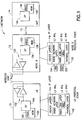
Figure 4 is a block diagram of a Node B protocol stack that illustrates the Radio Network Layer that controls making persistent resource allocations to UEs; and -
Figure 5 depicts a flowchart illustrating one non-limiting example of a method for practicing the exemplary embodiments of this invention.
-
- In an aspect thereof, the exemplary embodiments of this invention reduce the signaling overhead by pre-allocating a pattern of transmission resources to a particular UE. This procedure may be referred to, in a non-limiting sense, as a persistent allocation or as a semi-static allocation, and implies an allocation of resources for more than one transmission interval (e.g., more than one sub-frame). The exemplary embodiments of this invention pertain to both the physical layer aspects and to Layer-3 signaling mechanisms to support persistent allocation. The use of the exemplary embodiments of this invention is applicable for both the uplink (UE to wireless network) and downlink (wireless network to UE).
- The use of the exemplary embodiments of this invention is particularly well-suited to, and provides enhanced operation for, UTRAN LTE. The UTRAN LTE relies on OFDMA in the DL and single carrier FDMA in the UL, where a default conventional assumption for both the DL and the UL is the use of fast scheduling/user multiplexing every 1.0 msec TTI (i.e., one time allocations). However, it should be appreciated that at least certain aspects of this invention have wider applicability, and may be employed in other types of networks and systems.
- Reference is made first to
Figure 1 for illustrating a simplified block diagram of various electronic devices that are suitable for use in practicing the exemplary embodiments of this invention. InFigure 1 awireless network 1 is adapted for communication with aUE 10 via a Node B (base station) 12. Thenetwork 1 may include at least one network control function (NCF) 14. TheUE 10 includes a data processor (DP) 10A, a memory (MEM) 10B that stores a program (PROG) 10C, and a suitable radio frequency (RF)transceiver 10D for bidirectional wireless communications with theNode B 12, which also includes aDP 12A, aMEM 12B that stores aPROG 12C, and asuitable RF transceiver 12D. TheNode B 12 is coupled via adata path 13 to theNCF 14 that also includes aDP 14A and aMEM 14B storing an associatedPROG 14C. At least one of thePROGs - The
UE 10 is assumed to include and implement aprotocol stack 10E containing at least layers L1 (PHY), L2 (RLL) and L3 (RNL), and typically higher layers as well (e.g., an IP layer). As is shown more particularly inFigure 4 , theNode B 12 is assumed to include and implement aprotocol stack 12E also containing at least layers L1 (PHY), L2 (RLL) and L3 (RNL), and typically also the higher layers as well (e.g., an IP layer). The L2 (MAC layer) of theNode B 12 includes the functionality of aPDCP 32B, and the L3 (RNL) includes the functionality of aRRC 34A, as discussed in further detail below. - In general, the various embodiments of the
UE 10 can include, but are not limited to, cellular phones, personal digital assistants (PDAs) having wireless communication capabilities, portable computers having wireless communication capabilities, image capture devices such as digital cameras having wireless communication capabilities, gaming devices having wireless communication capabilities, music storage and playback appliances having wireless communication capabilities, Internet appliances permitting wireless Internet access and browsing, as well as portable units or terminals that incorporate combinations of such functions. - The embodiments of this invention may be implemented by computer software executable by the
DP 10A of theUE 10 and theDP 12A of the Node B, or by hardware, or by a combination of software and hardware. - The
MEMs DPs - In accordance with the exemplary embodiments of this invention, a network element, such as the
Node B 12, pre-allocates transmission resources to at least oneUE 10, and thus avoids sending a Layer-1 allocation table for every allocation per sub-frame.Figure 2 shows a non-limiting example where transmission resources are periodically allocated to aUE 10 in the frequency-time domain. This example assumes localized transmission in the frequency domain in the allocated sub-frames, but it should be realized that the process can be generalized to cover cases with distributed transmission in the frequency domain per sub-frame. The example inFigure 2 illustrates a case where only persistent allocation is used for theUE 10. However, as illustrated inFigure 3 , a hybrid approach can also be adapted where both persistent allocation and one-time allocation is used. This permits temporarily increasing the capacity allocation to aUE 10 if the granted persistent allocation is found to be insufficient for some relatively short (temporary) period of time. - Note that in the example of
Figure 2 , theUE 10 is assigned the same band of frequencies in each consecutive sub-frame, whereas in the example ofFigure 3 , theUE 10 is assigned different frequency bands per sub-frame. - Note should also be made of the fact that the exemplary persistent allocation schemes shown in
Figures 2 and 3 are both applicable for the UL and/or the DL. - The use of persistent allocations in accordance with the exemplary embodiments of this invention is particularly well suited for, but not restricted to, those services that require constant or approximately constant bit rates, such as VoIP and streaming, as two non-limiting examples, where it is known in advance how many transmission resources are needed by the
UE 10. - The use of the persistent allocation in accordance with the exemplary embodiments of this invention provides a signaling scheme compatible with UTRAN LTE. Referring to
Figure 4 , there is shown a block diagram of theNode B 12protocol stack 12E. Layer 1 (L1) is the physical (PHY)layer 30, Layer 2 (L2) is theMAC layer 32 and Layer 3 (L3) is the Radio Network Layer (RNL) 34. Above Layer 3 are typically other layers, agents and entities, such as anIP layer 36, aQoS agent 38 and aSecurity agent 40, that are not particularly germane to an understanding of this invention. Various SAPs are shown inFigure 4 for convenience, as are the various control (C) paths (CPDCP, CMAC, CPHY) between the L3 RRC and the underlying L2 and L1 entities. ThePHY layer 30 includes a PHY controller/manager function 30A, theRadio Link Layer 32 includes a MAC controller/manager function 32A and a PDCP controller/manager function 32B, and theRadio Network Layer 34 is assumed to include a RRC controller/manager function 34A. - In accordance with the exemplary embodiments of this invention, the
RRC entity 34A at L3 includes a persistent allocation manager function that controls the persistent allocation of resources toUEs 10. When a new data flow is set up, theRRC entity 34A decides whether persistent allocation should be used. If persistent allocation is used, then the BTS, which forms a part of theNode B 12, informs theUE 10 of the allocated resources via RRC signaling, as well as thePHY 30A (L1) via CPHY control messages. This implies that the use of the separate L1 signaling to the UE 10 (via an allocation table) for each allocation is avoided, which can provide a significant advantage due to the reduction in signaling overhead. - Since RRC (L3) signaling is utilized to inform the
UE 10, the signaling message is received at theUE 10 at L3. Information in the received signaling message is subsequently passed on to the UE PHY. - As non-limiting examples, the RRC signaling message and/or the CPHY control message may comprise: a frequency resource(s) ID, a repetition factor (e.g., once every X TTIs), SFN mod X (e.g., to "synchronize" the allocation at the
Node B 12 and the UE 10), and a hopping sequence (e.g., if the allocated frequency resources periodically change to provide frequency diversity). In other embodiments, the RRC signaling message and/or the CPHY control message may comprise a parameter indicating the "duration" of the allocation. In further embodiments, such a duration parameter may not be necessary because the Node B sends a specific message to release previously assigned persistent allocations. - The determination by the persistent allocation manager function whether or not a persistent allocation is used may be based on, as non-limiting examples, one or more of: the type of data flow being set up (e.g., VoIP, streaming), any specific QoS requirements of the
UE 10 setting up the data flow, a total number of active UEs in a cell, the types of data flows (and resource allocations) currently in use by other UEs, and the current load in the network, in particular the DL load caused by L1 control signaling (e.g., allocation table). The use of the persistent allocation in accordance with the exemplary embodiments of this invention may be particularly advantageous during high load conditions. - To even further enhance the use and flexibility of this approach, the Node-B MAC layer packet scheduler (part of
MAC entity 32A) may be enabled to propose new persistent allocations forUEs 10 and/or modifications of existing persistent allocations to higher or lower data rates. This is desirable since throughput monitoring and buffer information is available at theMAC layer 32. However, the persistent allocation manager function that is resident in theRadio Network Layer 34 makes the final determination as to whether to comply with the suggestions received from theL2 MAC entity 32A packet scheduler. - It should also be noted that the persistent allocation manager in L3 may also receive inputs from other layers, such as L1 (PHY), that affect the persistent resource allocation (e.g., channel quality indications). In general, it may be preferred to make the interface between the persistent allocation manager functionality and the PHY as generic as possible, such that the persistent allocation manager function may make use of both cell-based and link-based measurements provided by PHY. Other examples of information that may be provided by PHY to the persistent allocation manager function include, but need not be limited to, one or both of the load per resource pool (frequency and/or time) and an optimal MCS (Modulation and Coding Scheme) to be persistently assigned to a
certain UE 10. - Note that this additional embodiment is optional, and is not required to implement the persistent allocation techniques in accordance with the exemplary embodiments of this invention.
-
Figure 5 depicts a flowchart illustrating one non-limiting example of a method for practicing the exemplary embodiments of this invention. The method includes: allocating resources to a user equipment for a data flow over a plurality of time intervals with a single signaling event at a wireless network radio network layer (501); and informing the user equipment of the allocated resources (502). - In other embodiments, the method further comprises: informing a physical layer control/manager function of the allocated resources. In further embodiments, informing the physical layer control/manager function of the allocated resources comprises using at least one CPHY control message. In other embodiments, wherein allocating is performed in response to a new data flow being set up. In further embodiments, informing the user equipment of the allocated resources comprises using radio resource control signaling. In other embodiments, allocating comprises considering only information available in the radio network layer.
- In further embodiments, allocating comprises considering, at least in part, information obtained from at least one layer other than the radio network layer. In other embodiments, the information comprises at least one of: a cell-based measurement, a link-based measurement, a channel quality indication, a load per frequency resource pool, a load per time resource pool, and a modulation and coding scheme. In further embodiments, the information is obtained from a component of a physical layer. In other embodiments, the information is obtained from a component of a medium access control layer.
- In other embodiments, the method further comprises: allocating at least one resource to accommodate fluctuations in radio resource requirements of the user equipment. In further embodiments, allocating is performed in response to a Node B medium access control layer packet scheduler proposing one of a new allocation or a modification of an existing allocation. In other embodiments, the method further comprises: determining whether a persistent allocation should be used or modified for a respective data flow, wherein allocating comprises in response to determining that a persistent allocation should be used or modified for a respective data flow, allocating the persistent allocation for the respective data flow. In further embodiments, determining whether persistent allocation should be used or modified for the respective data flow comprises considering at least one of: a type of the respective data flow, QoS requirements of a respective user equipment associated with the respective data flow, a total number of active user equipments in a cell, types of data flows currently in use by other user equipments, resource allocations of the other user equipments, and current load in an associated network. In other embodiments, the plurality of time intervals comprises a plurality of sub-frames.
- Based on the foregoing it should be apparent that the exemplary embodiments of this invention provide a method, apparatus and computer program product(s) to provide a persistent allocation manager function in a Radio Network Layer of a wireless network component for selectively allocating resources to UEs for a plurality of sub-frame intervals with a single signaling event so as to reduce an amount of signaling to the UEs. The persistent allocation may be made in accordance only with information available in the Radio Network Layer, or in accordance with information obtained from another layer or layers, such as the Radio Link Layer. The persistent resource allocation may be made in conjunction with a temporary resource allocation to accommodate fluctuations in radio resource requirements by a particular UE.
- As noted above, while the exemplary embodiments have been described above in the context of the UTRAN-LTE system, it should be appreciated that the exemplary embodiments of this invention are not limited for use with only this one particular type of wireless communication system, and that they may be used to advantage in other wireless communication systems.
- In general, the various embodiments may be implemented in hardware or special purpose circuits, software, logic or any combination thereof. For example, some aspects may be implemented in hardware, while other aspects may be implemented in firmware or software which may be executed by a controller, microprocessor or other computing device, although the invention is not limited thereto. While various aspects of the invention may be illustrated and described as block diagrams, flow charts, or using some other pictorial representation, it is well understood that these blocks, apparatus, systems, techniques or methods described herein may be implemented in, as non-limiting examples, hardware, software, firmware, special purpose circuits or logic, general purpose hardware or controller or other computing devices, or some combination thereof.
Embodiments of the inventions may be practiced in various components such as integrated circuit modules. The design of integrated circuits is by and large a highly automated process. Complex and powerful software tools are available for converting a logic level design into a semiconductor circuit design ready to be etched and formed on a semiconductor substrate.
Programs, such as those provided by Synopsys, Inc. of Mountain View, California and Cadence Design, of San Jose, California automatically route conductors and locate components on a semiconductor chip using well established rules of design as well as libraries of pre-stored design modules. Once the design for a semiconductor circuit has been completed, the resultant design, in a standardized electronic format (e.g., Opus, GDSII, or the like) may be transmitted to a semiconductor fabrication facility or "fab" for fabrication. - Various modifications and adaptations may become apparent to those skilled in the relevant arts in view of the foregoing description, when read in conjunction with the accompanying drawings. However, any and all modifications of the teachings of this invention will still fall within the scope of the non-limiting embodiments of this invention.
Furthermore, some of the features of the various non-limiting embodiments of this invention may be used to advantage without the corresponding use of other features. As such, the foregoing description should be considered as merely illustrative of the principles, teachings and exemplary embodiments of this invention, and not in limitation thereof.
Claims (9)
- A method for allocating transmission resources to a User Equipment, UE (10), in a Universal Terrestrial Radio Access Network, UTRAN, network by a Node B (12) comprising a Radio Network Layer, RNL, (34) including a Radio Resource Control, RRC, entity (34a), characterized in that the method comprises:determining, by said RRC entity (34a) of the Node B (12), a need for a persistent transmission resource allocation to said UE (10) or a need for modifying it in response to a data flow set up with said UE (10) and via said Node B (12) wherein the persistent transmission resource allocation implies an allocation of transmission resources for more than one transmission interval, and wherein the determination comprises considering at least one of: a type of the data flow, QoS requirements of the user equipment associated with the data flow, a total number of active user equipments in a cell, types of data flows currently in use by other user equipments, resource allocations of the other user equipments, and current load in said UTRAN;in response to the determination of the need for the persistent transmission resource allocation to said UE (10) or the need for modifying it allocating, by a persistent allocation manager function of the RRC entity (34a) in the RNL, transmission resources to the UE(10) for the data flow over a plurality of time transmission intervals; and informing the UE (10) of the allocated transmission resources with a single RRC signaling message at said RNL.
- The method of claim 1, further comprising:informing a physical layer control/manager function of said Node B.
- The method of claim 1, wherein allocating comprises considering only information available in the radio network layer.
- The method of claim 1, wherein allocating comprises considering, at least in part, information obtained from at least one layer other than the radio network layer.
- The method of claim 4, wherein the information comprises at least one of: a cell-based measurement, a link-based measurement, a channel quality indication, a load per frequency resource pool, a load per time resource pool, and a modulation and coding scheme.
- The method of claim 1, further comprising:allocating at least one resource to accommodate fluctuations in radio resource requirements of the user equipment.
- A computer program comprising program instructions embodied on a tangible computer-readable medium, execution of the program instructions by a processor resulting in operations according to one of claims 1, 2, 4, or 5.
- A Node B (12) in a Universal Terrestrial Radio Access Network, UTRAN, characterized in that said Node B (12) comprises a Radio Network Layer, RNL, (34) including a Radio Resource Control, RRC, entity (34a) wherein :the RRC entity (34a) of the Node B is configured to determine a need for a persistent transmission resource allocation to a User Equipment, UE (10), or a need for modifying it in response to a data flow set up with said UE (10) and via said Node B (12) wherein the persistent transmission resource allocation implies an allocation of transmission resources for more than one transmission interval, and whereinthe determination comprises considering at least one of: a type of the data flow, QoS requirements of the user equipment associated with the data flow, a total number of active user equipments in a cell, types of data flows currently in use by other user equipments, resource allocations of the other user equipments, and current load in said UTRAN, andin response to the determination of the need for persistent transmission resource allocation to said UE (10) or the need for modifying it, the RRC entity (34a) of the Node B (12) is further configured to allocate persistent transmission resources to said UE (10) for the data flow over a plurality of time transmission intervals; anda transmitter coupled to the radio network layer component, wherein the transmitter is configured to transmit information indicative of the persistent allocated transmission resources to the UE (10) with a single Radio Resource Control, RRC, signaling message at said RNL.
- The Node B of claim 8, wherein the RRC entity (34a) of the radio network layer component is further configured to inform a physical layer control/manager function of said Node B(12) of the allocated resources.
Applications Claiming Priority (2)
| Application Number | Priority Date | Filing Date | Title |
|---|---|---|---|
| US76508106P | 2006-02-03 | 2006-02-03 | |
| PCT/IB2007/000243 WO2007088468A2 (en) | 2006-02-03 | 2007-02-01 | Apparatus, method, and computer program product providing persistent uplink and downlink resource allocation |
Publications (3)
| Publication Number | Publication Date |
|---|---|
| EP1987635A2 EP1987635A2 (en) | 2008-11-05 |
| EP1987635A4 EP1987635A4 (en) | 2012-02-15 |
| EP1987635B1 true EP1987635B1 (en) | 2018-11-07 |
Family
ID=38327757
Family Applications (1)
| Application Number | Title | Priority Date | Filing Date |
|---|---|---|---|
| EP07705517.6A Active EP1987635B1 (en) | 2006-02-03 | 2007-02-01 | Apparatus, method, and computer program product providing persistent uplink and downlink resource allocation |
Country Status (6)
| Country | Link |
|---|---|
| US (2) | US8452295B2 (en) |
| EP (1) | EP1987635B1 (en) |
| JP (1) | JP4891345B2 (en) |
| CN (1) | CN101411237B (en) |
| TW (1) | TWI375441B (en) |
| WO (1) | WO2007088468A2 (en) |
Families Citing this family (17)
| Publication number | Priority date | Publication date | Assignee | Title |
|---|---|---|---|---|
| KR101254801B1 (en) * | 2006-04-19 | 2013-04-15 | 삼성전자주식회사 | Method and apparatus for transmitting/receiving a data control channel in a packet data communication system |
| CN101529963B (en) | 2006-10-27 | 2012-05-30 | Lm爱立信电话有限公司 | Method for allocating radio resources , user equipment and communication network node |
| KR101328164B1 (en) * | 2007-01-12 | 2013-11-13 | 삼성전자주식회사 | Method and apparatus of allocating resources in wireless communication system |
| KR101377961B1 (en) * | 2007-07-27 | 2014-03-25 | 엘지전자 주식회사 | Method Of Transmitting Packet For Reducing Header Overhead |
| US7839824B2 (en) * | 2007-07-31 | 2010-11-23 | Beceem Communications Inc. | Allocation of periodically distributed frames of wireless communication |
| GB0714927D0 (en) | 2007-08-01 | 2007-09-12 | Nokia Siemens Networks Oy | Resource allocation |
| MX2010002748A (en) | 2007-09-11 | 2011-02-25 | Wi Lan Inc | Persistent resource allocation. |
| KR20090030562A (en) | 2007-09-20 | 2009-03-25 | 엘지전자 주식회사 | Method of packet transmission for resource allocation in broadband wireless access system |
| WO2009057391A1 (en) | 2007-10-31 | 2009-05-07 | Nec Corporation | Resource allocation method in communication system, resource allocation system, and base station used for the same |
| US8208433B2 (en) * | 2008-02-19 | 2012-06-26 | Broadcom Corporation | Method and apparatus for allocating resources in wireless communication system |
| US8964536B2 (en) * | 2009-10-05 | 2015-02-24 | Qualcomm Incorporated | Apparatus and method for dynamic load balancing in a multi-carrier wireless communication system |
| WO2011095061A1 (en) * | 2010-02-02 | 2011-08-11 | 中国移动通信集团公司 | Method and device for scheduling downlink subframes |
| EP2564650B1 (en) | 2010-04-30 | 2014-12-17 | Telefonaktiebolaget LM Ericsson (publ) | A device for low priority traffic scheduling |
| JP5054804B2 (en) * | 2010-05-28 | 2012-10-24 | 株式会社エヌ・ティ・ティ・ドコモ | Radio base station and radio resource allocation method |
| WO2012052071A1 (en) * | 2010-10-18 | 2012-04-26 | Telefonaktiebolaget L M Ericsson (Publ) | Communication scheduling based on priority and resource utilization |
| WO2016070413A1 (en) * | 2014-11-07 | 2016-05-12 | Mediatek Singapore Pte. Ltd. | Methods for enhanced contention based access response message |
| CN105991224B (en) * | 2015-02-13 | 2019-07-02 | 中兴通讯股份有限公司 | A kind of transfer control method and device of upstream data |
Family Cites Families (27)
| Publication number | Priority date | Publication date | Assignee | Title |
|---|---|---|---|---|
| US6904110B2 (en) * | 1997-07-31 | 2005-06-07 | Francois Trans | Channel equalization system and method |
| GB0004088D0 (en) * | 2000-02-21 | 2000-04-12 | Nokia Networks Oy | Packet data services in a telecommunications system |
| US6714515B1 (en) * | 2000-05-16 | 2004-03-30 | Telefonaktiebolaget Lm Ericsson (Publ) | Policy server and architecture providing radio network resource allocation rules |
| US20020071407A1 (en) * | 2000-07-08 | 2002-06-13 | Samsung Electronics Co., Ltd. | HARQ method in a CDMA mobile communication system |
| CA2376962A1 (en) * | 2001-04-02 | 2002-10-02 | Lucent Technologies Inc. | Method and system for umts packet transmission scheduling on uplink channels |
| AU2002302870A1 (en) * | 2002-05-08 | 2003-11-11 | Nokia Corporation | Dynamic allocation of a radio resource |
| KR100917042B1 (en) * | 2002-08-14 | 2009-09-10 | 엘지전자 주식회사 | Transmission method for broadcasting and multicast data in mobile radio communication system |
| US7623540B2 (en) * | 2002-12-31 | 2009-11-24 | Vixs Systems, Inc. | Method and apparatus for channel allocation in a wireless local area network (WLAN) |
| KR20050038977A (en) * | 2003-10-23 | 2005-04-29 | 삼성전자주식회사 | System and method for transmitting/receiving resource allocation information in a radio communication system |
| CN1691539A (en) * | 2004-04-30 | 2005-11-02 | 皇家飞利浦电子股份有限公司 | Universal MIMO combined detecting method and apparatus for MIMO wireless communication system |
| US8259752B2 (en) * | 2004-05-07 | 2012-09-04 | Interdigital Technology Corporation | Medium access control layer architecture for supporting enhanced uplink |
| CN101053269B (en) * | 2004-10-29 | 2011-09-28 | 艾利森电话股份有限公司 | Resource allocation in communication networks |
| WO2006065174A1 (en) * | 2004-12-13 | 2006-06-22 | Telefonaktiebolaget Lm Ericsson (Publ) | Latency reduction when setting up an uplink wireless communications channel |
| US20060203724A1 (en) * | 2005-03-08 | 2006-09-14 | Donna Ghosh | Multi-carrier, multi-flow, reverse link medium access control for a communication system |
| US20060221933A1 (en) * | 2005-03-29 | 2006-10-05 | Bauer Markus G | Managing internet protocol based resources in a packet-based access network |
| US20070058595A1 (en) * | 2005-03-30 | 2007-03-15 | Motorola, Inc. | Method and apparatus for reducing round trip latency and overhead within a communication system |
| US8031583B2 (en) * | 2005-03-30 | 2011-10-04 | Motorola Mobility, Inc. | Method and apparatus for reducing round trip latency and overhead within a communication system |
| US8085657B2 (en) * | 2005-04-01 | 2011-12-27 | Sony Corporation | Flow control in a cellular communication system |
| EP1869929B1 (en) * | 2005-04-13 | 2015-11-11 | Vringo Infrastructure Inc. | Techniques for radio link resource management in wireless networks carrying packet traffic |
| US8744465B2 (en) * | 2005-06-16 | 2014-06-03 | Qualcomm Incorporated | Resource allocation method in a communication system |
| US7558294B2 (en) * | 2005-07-27 | 2009-07-07 | Intellon Corporation | Time synchronization in a network |
| US7822059B2 (en) * | 2005-07-27 | 2010-10-26 | Atheros Communications, Inc. | Managing contention-free time allocations in a network |
| MY143970A (en) * | 2005-10-07 | 2011-07-29 | Interdigital Tech Corp | Method and system for providing control information for supporting high speed downlink and uplink |
| EP3136671A1 (en) * | 2005-10-21 | 2017-03-01 | Apple Inc. | Multiplexing schemes for ofdma |
| US7567543B2 (en) * | 2005-10-24 | 2009-07-28 | Nec Laboratories America, Inc. | Method and apparatus for cross layer resource allocation for wireless backhaul networks |
| US7852826B2 (en) * | 2006-09-29 | 2010-12-14 | Intel Corporation | Techniques to communication MAP information elements in a wireless network |
| US20090135807A1 (en) * | 2007-11-27 | 2009-05-28 | Shweta Shrivastava | Persistent scheduling of harq retransmissions |
-
2007
- 2007-02-01 JP JP2008552915A patent/JP4891345B2/en active Active
- 2007-02-01 EP EP07705517.6A patent/EP1987635B1/en active Active
- 2007-02-01 US US11/700,999 patent/US8452295B2/en active Active
- 2007-02-01 WO PCT/IB2007/000243 patent/WO2007088468A2/en active Application Filing
- 2007-02-01 CN CN200780009459.6A patent/CN101411237B/en active Active
- 2007-02-02 TW TW096103885A patent/TWI375441B/en active
-
2013
- 2013-04-19 US US13/866,316 patent/US9357539B2/en active Active
Non-Patent Citations (2)
| Title |
|---|
| "Radio Sub - system Link Control; GSM 05.02", ETSI STANDARD, EUROPEAN TELECOMMUNICATIONS STANDARDS INSTITUTE (ETSI), SOPHIA ANTIPOLIS CEDEX, FRANCE, no. 3.8.0 ( Release 95, phase 1), 1 December 1995 (1995-12-01), XP014041246 * |
| ANONYMOUS: "What is RRC and RAB? - telecomHall", 20 May 2013 (2013-05-20), XP055311307, Retrieved from the Internet <URL:http://www.telecomhall.com/what-is-rrc-and-rab.aspx> [retrieved on 20161017] * |
Also Published As
| Publication number | Publication date |
|---|---|
| TWI375441B (en) | 2012-10-21 |
| US20070184842A1 (en) | 2007-08-09 |
| JP4891345B2 (en) | 2012-03-07 |
| WO2007088468A2 (en) | 2007-08-09 |
| JP2009525656A (en) | 2009-07-09 |
| EP1987635A4 (en) | 2012-02-15 |
| EP1987635A2 (en) | 2008-11-05 |
| CN101411237A (en) | 2009-04-15 |
| US9357539B2 (en) | 2016-05-31 |
| CN101411237B (en) | 2014-09-10 |
| US8452295B2 (en) | 2013-05-28 |
| US20140314051A1 (en) | 2014-10-23 |
| WO2007088468A3 (en) | 2007-11-29 |
| TW200742371A (en) | 2007-11-01 |
Similar Documents
| Publication | Publication Date | Title |
|---|---|---|
| EP1987635B1 (en) | Apparatus, method, and computer program product providing persistent uplink and downlink resource allocation | |
| US11026250B2 (en) | Scheduling method, device, and system | |
| RU2676873C2 (en) | Apparatus and method for synchronous multiplexing and multiple access for different latency targets utilising thin control | |
| JP4728301B2 (en) | User apparatus, transmission method, and communication system | |
| US9185696B2 (en) | Adaptive scheme for lowering uplink control overhead | |
| EP2198663B1 (en) | Uplink scheduling grant for time division duplex with asymmetric uplink and downlink configuration | |
| JP5020263B2 (en) | Allocation of uplink resources in mobile communication systems | |
| US20170347394A1 (en) | User equipment, feedback control method, and retransmission control method | |
| WO2017118229A1 (en) | Resource scheduling method, device and system | |
| CN110999365B (en) | Method for transmitting data and terminal equipment | |
| JP2016146651A (en) | Wireless communication method and apparatus for reporting traffic volume measurement information to support enhanced uplink data transmission | |
| WO2009022295A2 (en) | Mapping of uplink ack in tdd with asymmetric frame structure | |
| CN112888031A (en) | Method, device and terminal for service transmission | |
| CN110430616B (en) | Resource determination method, related equipment and system | |
| WO2018027918A1 (en) | Method and apparatus for transmitting uplink channel | |
| CN110839284A (en) | Scheduling request resource determining and configuring method, equipment and device | |
| CN107295643B (en) | Scheduling method, device and equipment | |
| CN112584532B (en) | Information determination method of uplink channel, terminal and network side equipment | |
| JP2020102883A (en) | Uplink information transmission method and device, base station, and user device | |
| JP5226099B2 (en) | User device, transmission method, communication system | |
| US20220141848A1 (en) | Communications device, infrastructure equipment and methods | |
| JP6802747B2 (en) | Base station equipment, terminal equipment, control methods, and programs | |
| WO2023208471A1 (en) | Apparatus, method and computer program for selection of sidelink resources between different rats |
Legal Events
| Date | Code | Title | Description |
|---|---|---|---|
| PUAI | Public reference made under article 153(3) epc to a published international application that has entered the european phase |
Free format text: ORIGINAL CODE: 0009012 |
|
| 17P | Request for examination filed |
Effective date: 20080901 |
|
| AK | Designated contracting states |
Kind code of ref document: A2 Designated state(s): AT BE BG CH CY CZ DE DK EE ES FI FR GB GR HU IE IS IT LI LT LU LV MC NL PL PT RO SE SI SK TR |
|
| RIN1 | Information on inventor provided before grant (corrected) |
Inventor name: MOGENSEN, PREBEN, E. Inventor name: PEDERSEN, KLAUS, I. Inventor name: ROSA, CLAUDIO |
|
| A4 | Supplementary search report drawn up and despatched |
Effective date: 20120116 |
|
| RIC1 | Information provided on ipc code assigned before grant |
Ipc: H04W 4/00 20090101ALI20120117BHEP Ipc: H04L 12/56 20060101AFI20120117BHEP |
|
| DAX | Request for extension of the european patent (deleted) | ||
| 17Q | First examination report despatched |
Effective date: 20130118 |
|
| RAP1 | Party data changed (applicant data changed or rights of an application transferred) |
Owner name: NOKIA CORPORATION |
|
| RAP1 | Party data changed (applicant data changed or rights of an application transferred) |
Owner name: NOKIA TECHNOLOGIES OY |
|
| STAA | Information on the status of an ep patent application or granted ep patent |
Free format text: STATUS: EXAMINATION IS IN PROGRESS |
|
| REG | Reference to a national code |
Ref country code: DE Ref legal event code: R079 Ref document number: 602007056728 Country of ref document: DE Free format text: PREVIOUS MAIN CLASS: H04L0012560000 Ipc: H04L0012700000 |
|
| GRAP | Despatch of communication of intention to grant a patent |
Free format text: ORIGINAL CODE: EPIDOSNIGR1 |
|
| STAA | Information on the status of an ep patent application or granted ep patent |
Free format text: STATUS: GRANT OF PATENT IS INTENDED |
|
| RIC1 | Information provided on ipc code assigned before grant |
Ipc: H04W 72/04 20090101ALN20180605BHEP Ipc: H04L 12/70 20130101AFI20180605BHEP |
|
| INTG | Intention to grant announced |
Effective date: 20180618 |
|
| GRAS | Grant fee paid |
Free format text: ORIGINAL CODE: EPIDOSNIGR3 |
|
| GRAA | (expected) grant |
Free format text: ORIGINAL CODE: 0009210 |
|
| STAA | Information on the status of an ep patent application or granted ep patent |
Free format text: STATUS: THE PATENT HAS BEEN GRANTED |
|
| AK | Designated contracting states |
Kind code of ref document: B1 Designated state(s): AT BE BG CH CY CZ DE DK EE ES FI FR GB GR HU IE IS IT LI LT LU LV MC NL PL PT RO SE SI SK TR |
|
| REG | Reference to a national code |
Ref country code: GB Ref legal event code: FG4D |
|
| REG | Reference to a national code |
Ref country code: CH Ref legal event code: EP Ref country code: AT Ref legal event code: REF Ref document number: 1063408 Country of ref document: AT Kind code of ref document: T Effective date: 20181115 |
|
| REG | Reference to a national code |
Ref country code: IE Ref legal event code: FG4D |
|
| REG | Reference to a national code |
Ref country code: DE Ref legal event code: R096 Ref document number: 602007056728 Country of ref document: DE |
|
| REG | Reference to a national code |
Ref country code: SE Ref legal event code: TRGR |
|
| REG | Reference to a national code |
Ref country code: NL Ref legal event code: MP Effective date: 20181107 |
|
| REG | Reference to a national code |
Ref country code: LT Ref legal event code: MG4D |
|
| REG | Reference to a national code |
Ref country code: AT Ref legal event code: MK05 Ref document number: 1063408 Country of ref document: AT Kind code of ref document: T Effective date: 20181107 |
|
| PG25 | Lapsed in a contracting state [announced via postgrant information from national office to epo] |
Ref country code: IS Free format text: LAPSE BECAUSE OF FAILURE TO SUBMIT A TRANSLATION OF THE DESCRIPTION OR TO PAY THE FEE WITHIN THE PRESCRIBED TIME-LIMIT Effective date: 20190307 Ref country code: FI Free format text: LAPSE BECAUSE OF FAILURE TO SUBMIT A TRANSLATION OF THE DESCRIPTION OR TO PAY THE FEE WITHIN THE PRESCRIBED TIME-LIMIT Effective date: 20181107 Ref country code: LV Free format text: LAPSE BECAUSE OF FAILURE TO SUBMIT A TRANSLATION OF THE DESCRIPTION OR TO PAY THE FEE WITHIN THE PRESCRIBED TIME-LIMIT Effective date: 20181107 Ref country code: AT Free format text: LAPSE BECAUSE OF FAILURE TO SUBMIT A TRANSLATION OF THE DESCRIPTION OR TO PAY THE FEE WITHIN THE PRESCRIBED TIME-LIMIT Effective date: 20181107 Ref country code: LT Free format text: LAPSE BECAUSE OF FAILURE TO SUBMIT A TRANSLATION OF THE DESCRIPTION OR TO PAY THE FEE WITHIN THE PRESCRIBED TIME-LIMIT Effective date: 20181107 Ref country code: BG Free format text: LAPSE BECAUSE OF FAILURE TO SUBMIT A TRANSLATION OF THE DESCRIPTION OR TO PAY THE FEE WITHIN THE PRESCRIBED TIME-LIMIT Effective date: 20190207 Ref country code: ES Free format text: LAPSE BECAUSE OF FAILURE TO SUBMIT A TRANSLATION OF THE DESCRIPTION OR TO PAY THE FEE WITHIN THE PRESCRIBED TIME-LIMIT Effective date: 20181107 |
|
| PG25 | Lapsed in a contracting state [announced via postgrant information from national office to epo] |
Ref country code: PT Free format text: LAPSE BECAUSE OF FAILURE TO SUBMIT A TRANSLATION OF THE DESCRIPTION OR TO PAY THE FEE WITHIN THE PRESCRIBED TIME-LIMIT Effective date: 20190307 Ref country code: NL Free format text: LAPSE BECAUSE OF FAILURE TO SUBMIT A TRANSLATION OF THE DESCRIPTION OR TO PAY THE FEE WITHIN THE PRESCRIBED TIME-LIMIT Effective date: 20181107 Ref country code: GR Free format text: LAPSE BECAUSE OF FAILURE TO SUBMIT A TRANSLATION OF THE DESCRIPTION OR TO PAY THE FEE WITHIN THE PRESCRIBED TIME-LIMIT Effective date: 20190208 |
|
| PG25 | Lapsed in a contracting state [announced via postgrant information from national office to epo] |
Ref country code: CZ Free format text: LAPSE BECAUSE OF FAILURE TO SUBMIT A TRANSLATION OF THE DESCRIPTION OR TO PAY THE FEE WITHIN THE PRESCRIBED TIME-LIMIT Effective date: 20181107 Ref country code: DK Free format text: LAPSE BECAUSE OF FAILURE TO SUBMIT A TRANSLATION OF THE DESCRIPTION OR TO PAY THE FEE WITHIN THE PRESCRIBED TIME-LIMIT Effective date: 20181107 Ref country code: PL Free format text: LAPSE BECAUSE OF FAILURE TO SUBMIT A TRANSLATION OF THE DESCRIPTION OR TO PAY THE FEE WITHIN THE PRESCRIBED TIME-LIMIT Effective date: 20181107 |
|
| REG | Reference to a national code |
Ref country code: DE Ref legal event code: R097 Ref document number: 602007056728 Country of ref document: DE |
|
| PG25 | Lapsed in a contracting state [announced via postgrant information from national office to epo] |
Ref country code: EE Free format text: LAPSE BECAUSE OF FAILURE TO SUBMIT A TRANSLATION OF THE DESCRIPTION OR TO PAY THE FEE WITHIN THE PRESCRIBED TIME-LIMIT Effective date: 20181107 Ref country code: RO Free format text: LAPSE BECAUSE OF FAILURE TO SUBMIT A TRANSLATION OF THE DESCRIPTION OR TO PAY THE FEE WITHIN THE PRESCRIBED TIME-LIMIT Effective date: 20181107 Ref country code: SK Free format text: LAPSE BECAUSE OF FAILURE TO SUBMIT A TRANSLATION OF THE DESCRIPTION OR TO PAY THE FEE WITHIN THE PRESCRIBED TIME-LIMIT Effective date: 20181107 |
|
| RAP2 | Party data changed (patent owner data changed or rights of a patent transferred) |
Owner name: NOKIA TECHNOLOGIES OY |
|
| PLBE | No opposition filed within time limit |
Free format text: ORIGINAL CODE: 0009261 |
|
| STAA | Information on the status of an ep patent application or granted ep patent |
Free format text: STATUS: NO OPPOSITION FILED WITHIN TIME LIMIT |
|
| REG | Reference to a national code |
Ref country code: CH Ref legal event code: PL |
|
| 26N | No opposition filed |
Effective date: 20190808 |
|
| GBPC | Gb: european patent ceased through non-payment of renewal fee |
Effective date: 20190207 |
|
| PG25 | Lapsed in a contracting state [announced via postgrant information from national office to epo] |
Ref country code: MC Free format text: LAPSE BECAUSE OF FAILURE TO SUBMIT A TRANSLATION OF THE DESCRIPTION OR TO PAY THE FEE WITHIN THE PRESCRIBED TIME-LIMIT Effective date: 20181107 Ref country code: SI Free format text: LAPSE BECAUSE OF FAILURE TO SUBMIT A TRANSLATION OF THE DESCRIPTION OR TO PAY THE FEE WITHIN THE PRESCRIBED TIME-LIMIT Effective date: 20181107 Ref country code: LU Free format text: LAPSE BECAUSE OF NON-PAYMENT OF DUE FEES Effective date: 20190201 |
|
| REG | Reference to a national code |
Ref country code: IE Ref legal event code: MM4A |
|
| PG25 | Lapsed in a contracting state [announced via postgrant information from national office to epo] |
Ref country code: CH Free format text: LAPSE BECAUSE OF NON-PAYMENT OF DUE FEES Effective date: 20190228 Ref country code: LI Free format text: LAPSE BECAUSE OF NON-PAYMENT OF DUE FEES Effective date: 20190228 |
|
| PG25 | Lapsed in a contracting state [announced via postgrant information from national office to epo] |
Ref country code: IE Free format text: LAPSE BECAUSE OF NON-PAYMENT OF DUE FEES Effective date: 20190201 Ref country code: GB Free format text: LAPSE BECAUSE OF NON-PAYMENT OF DUE FEES Effective date: 20190207 |
|
| PG25 | Lapsed in a contracting state [announced via postgrant information from national office to epo] |
Ref country code: FR Free format text: LAPSE BECAUSE OF NON-PAYMENT OF DUE FEES Effective date: 20190228 |
|
| PG25 | Lapsed in a contracting state [announced via postgrant information from national office to epo] |
Ref country code: TR Free format text: LAPSE BECAUSE OF FAILURE TO SUBMIT A TRANSLATION OF THE DESCRIPTION OR TO PAY THE FEE WITHIN THE PRESCRIBED TIME-LIMIT Effective date: 20181107 |
|
| PG25 | Lapsed in a contracting state [announced via postgrant information from national office to epo] |
Ref country code: CY Free format text: LAPSE BECAUSE OF FAILURE TO SUBMIT A TRANSLATION OF THE DESCRIPTION OR TO PAY THE FEE WITHIN THE PRESCRIBED TIME-LIMIT Effective date: 20181107 |
|
| PG25 | Lapsed in a contracting state [announced via postgrant information from national office to epo] |
Ref country code: HU Free format text: LAPSE BECAUSE OF FAILURE TO SUBMIT A TRANSLATION OF THE DESCRIPTION OR TO PAY THE FEE WITHIN THE PRESCRIBED TIME-LIMIT; INVALID AB INITIO Effective date: 20070201 |
|
| PGFP | Annual fee paid to national office [announced via postgrant information from national office to epo] |
Ref country code: SE Payment date: 20230110 Year of fee payment: 17 Ref country code: IT Payment date: 20230110 Year of fee payment: 17 Ref country code: BE Payment date: 20230117 Year of fee payment: 17 |
|
| PGFP | Annual fee paid to national office [announced via postgrant information from national office to epo] |
Ref country code: DE Payment date: 20231229 Year of fee payment: 18 |