EP1983174B1 - Apparatus and method of operating a gas turbine engine at start-up - Google Patents
Apparatus and method of operating a gas turbine engine at start-up Download PDFInfo
- Publication number
- EP1983174B1 EP1983174B1 EP08250900.1A EP08250900A EP1983174B1 EP 1983174 B1 EP1983174 B1 EP 1983174B1 EP 08250900 A EP08250900 A EP 08250900A EP 1983174 B1 EP1983174 B1 EP 1983174B1
- Authority
- EP
- European Patent Office
- Prior art keywords
- fuel
- engine
- starter
- oil
- generator
- Prior art date
- Legal status (The legal status is an assumption and is not a legal conclusion. Google has not performed a legal analysis and makes no representation as to the accuracy of the status listed.)
- Expired - Fee Related
Links
- 238000000034 method Methods 0.000 title claims description 11
- 239000000446 fuel Substances 0.000 claims description 91
- 239000007858 starting material Substances 0.000 claims description 34
- 239000003921 oil Substances 0.000 claims description 30
- 239000007789 gas Substances 0.000 claims description 18
- 238000001816 cooling Methods 0.000 claims description 15
- 239000010705 motor oil Substances 0.000 claims description 4
- 239000002828 fuel tank Substances 0.000 description 10
- 238000002485 combustion reaction Methods 0.000 description 4
- 230000001141 propulsive effect Effects 0.000 description 3
- 230000003068 static effect Effects 0.000 description 3
- 238000011109 contamination Methods 0.000 description 2
- 230000005611 electricity Effects 0.000 description 2
- 238000012360 testing method Methods 0.000 description 2
- 230000002411 adverse Effects 0.000 description 1
- 239000010724 circulating oil Substances 0.000 description 1
- 230000006835 compression Effects 0.000 description 1
- 238000007906 compression Methods 0.000 description 1
- 238000007796 conventional method Methods 0.000 description 1
- 239000012530 fluid Substances 0.000 description 1
- 231100001261 hazardous Toxicity 0.000 description 1
- 238000012423 maintenance Methods 0.000 description 1
- 229910052751 metal Inorganic materials 0.000 description 1
- 239000002184 metal Substances 0.000 description 1
- 150000002739 metals Chemical class 0.000 description 1
- 239000000203 mixture Substances 0.000 description 1
- 238000005086 pumping Methods 0.000 description 1
- 238000012546 transfer Methods 0.000 description 1
Images
Classifications
-
- F—MECHANICAL ENGINEERING; LIGHTING; HEATING; WEAPONS; BLASTING
- F02—COMBUSTION ENGINES; HOT-GAS OR COMBUSTION-PRODUCT ENGINE PLANTS
- F02C—GAS-TURBINE PLANTS; AIR INTAKES FOR JET-PROPULSION PLANTS; CONTROLLING FUEL SUPPLY IN AIR-BREATHING JET-PROPULSION PLANTS
- F02C7/00—Features, components parts, details or accessories, not provided for in, or of interest apart form groups F02C1/00 - F02C6/00; Air intakes for jet-propulsion plants
- F02C7/22—Fuel supply systems
- F02C7/224—Heating fuel before feeding to the burner
-
- F—MECHANICAL ENGINEERING; LIGHTING; HEATING; WEAPONS; BLASTING
- F02—COMBUSTION ENGINES; HOT-GAS OR COMBUSTION-PRODUCT ENGINE PLANTS
- F02C—GAS-TURBINE PLANTS; AIR INTAKES FOR JET-PROPULSION PLANTS; CONTROLLING FUEL SUPPLY IN AIR-BREATHING JET-PROPULSION PLANTS
- F02C7/00—Features, components parts, details or accessories, not provided for in, or of interest apart form groups F02C1/00 - F02C6/00; Air intakes for jet-propulsion plants
- F02C7/12—Cooling of plants
- F02C7/14—Cooling of plants of fluids in the plant, e.g. lubricant or fuel
-
- F—MECHANICAL ENGINEERING; LIGHTING; HEATING; WEAPONS; BLASTING
- F02—COMBUSTION ENGINES; HOT-GAS OR COMBUSTION-PRODUCT ENGINE PLANTS
- F02C—GAS-TURBINE PLANTS; AIR INTAKES FOR JET-PROPULSION PLANTS; CONTROLLING FUEL SUPPLY IN AIR-BREATHING JET-PROPULSION PLANTS
- F02C7/00—Features, components parts, details or accessories, not provided for in, or of interest apart form groups F02C1/00 - F02C6/00; Air intakes for jet-propulsion plants
- F02C7/26—Starting; Ignition
- F02C7/268—Starting drives for the rotor, acting directly on the rotor of the gas turbine to be started
- F02C7/275—Mechanical drives
-
- F—MECHANICAL ENGINEERING; LIGHTING; HEATING; WEAPONS; BLASTING
- F02—COMBUSTION ENGINES; HOT-GAS OR COMBUSTION-PRODUCT ENGINE PLANTS
- F02C—GAS-TURBINE PLANTS; AIR INTAKES FOR JET-PROPULSION PLANTS; CONTROLLING FUEL SUPPLY IN AIR-BREATHING JET-PROPULSION PLANTS
- F02C7/00—Features, components parts, details or accessories, not provided for in, or of interest apart form groups F02C1/00 - F02C6/00; Air intakes for jet-propulsion plants
- F02C7/32—Arrangement, mounting, or driving, of auxiliaries
-
- Y—GENERAL TAGGING OF NEW TECHNOLOGICAL DEVELOPMENTS; GENERAL TAGGING OF CROSS-SECTIONAL TECHNOLOGIES SPANNING OVER SEVERAL SECTIONS OF THE IPC; TECHNICAL SUBJECTS COVERED BY FORMER USPC CROSS-REFERENCE ART COLLECTIONS [XRACs] AND DIGESTS
- Y02—TECHNOLOGIES OR APPLICATIONS FOR MITIGATION OR ADAPTATION AGAINST CLIMATE CHANGE
- Y02T—CLIMATE CHANGE MITIGATION TECHNOLOGIES RELATED TO TRANSPORTATION
- Y02T50/00—Aeronautics or air transport
- Y02T50/60—Efficient propulsion technologies, e.g. for aircraft
Definitions
- the present invention relates to a method and apparatus for cooling a starter/generator of a gas turbine engine at start-up.
- the starter is a variable frequency starter/generator that has a built-in pump for pumping oil through the starter to a dedicated closed circulating oil cooling circuit to transfer the heat generated from the starter to the oil in the oil circuit.
- the heated oil is then cooled by a flow of fuel via a heat exchanger.
- the fuel is pumped to the heat exchanger and returned to a fuel tank housed within the aircraft (conventionally known as a fuel return to tank cooling system).
- This method relies on the fuel mass in the aircraft's fuel tank acting as an external thermal sink to remove heat from the VFSG oil circuit. Because there is a finite amount of fuel, this system is limited to the amount of heat that it can dissipate. In addition, there are problems in the fuel balance within aircraft fuel tanks and fuel tank contamination.
- the thermal mass of the fluids and metals in the cooling circuits could be used as a simple static thermal sink, however, this method is of limited use due to the limited thermal capacity in the cooling circuits.
- Increasing the fuel volume in the loop would increase the thermal sink capacity, which means a large amount of fuel being stored on engine, and hence adversely increases the weight of the engine and causes an unnecessary fire hazard for the engine.
- US2006/260323 A1 discloses several improvements to an aircraft turbine engine and Auxiliary Power Unit (APU, as well as methods of using these improvements in routine and emergency aircraft operations.
- the improvements comprise the addition of cockpit-controllable clutches that can be used to independently disconnect the engine's integrated drive generator (IDG), engine driven pump (EDP), fuel pump, and oil pump from the engine gearbox. These engine components may then be connected to air turbines by the use of additional clutches and then powered by the turbines. Similar arrangements are provided for the APU components. Cranking pads, attached to various engine and APU components, are disclosed to provide a means for externally powering the components for testing purposes and to assist with engine and APU start.
- IDG integrated drive generator
- EDP engine driven pump
- fuel pump fuel pump
- oil pump oil pump
- Similar arrangements are provided for the APU components. Cranking pads, attached to various engine and APU components, are disclosed to provide a means for externally powering the components for testing purposes and to assist with engine and APU start.
- EP1683947 A2 discloses a relatively simple way to automatically turn on and off the fuel to a starter/generator cooling system during engine start.
- the present invention takes advantage of a fuel pressure rise provided by an engine fuel boost pump during the period from engine start to engine idle conditions. This pressure rise is used to stroke a shutoff valve in a fuel return to tank valve (FRTTV), which shuts off the starter generator cooling fuel flow. This shutoff occurs automatically with no other external input from, for example, an engine controller.
- FRTTV fuel return to tank valve
- a check valve is also included that prevents back flow through the FRTTV in the event of an engine start with no aircraft pumps running.
- a as turbine engine comprising a turbine and a compressor connected via a shaft, a main fuel supply line for supplying fuel to a combustor that is positioned to release expanding hot gases to the turbine, the engine further comprises a first fuel and oil heat exchanger associated with an engine starter/generator that is connected to the shaft via a gearbox assembly, the engine is characterised by a re-circulating fuel circuit positioned on the main fuel supply line and comprising a second fuel/oil heat exchanger and a fuel accumulator, the re-circulating fuel circuit cools the oil in the starter/generator via the first fuel and oil heat exchanger.
- the second fuel/oil heat exchanger is fluidly connected to an engine oil circuit.
- the first fuel/oil heater exchanger is fluidly connected to the starter/generator.
- the circuit comprises a fuel filter and which may be positioned between the second fuel/oil heat exchanger and the combustor.
- the circuit comprises a shut off valve that is provided to stop fuel return flow during normal engine running.
- a method of operating a gas turbine engine comprising a turbine and a compressor connected via a shaft, a main fuel supply line for supplying fuel to a combustor that is positioned to release expanding hot gases to the turbine, the engine further comprises a starter/generator connected to the shaft via a gearbox assembly, the method is characterised the step of during engine start up fuel is circulated in a re-circulating fuel circuit positioned on the main fuel supply line and which comprises a first fuel/oil heat exchanger, for cooling the oil in the starter/generator oil circuit, and a fuel accumulator.
- a further step comprises supplying the cooled fuel to the starter/generator for cooling.
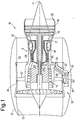
- FIG. 1 shows a ducted fan gas turbine engine generally indicated at 10 and comprising three main rotational shafts, however, the present invention is equally applicable to an engine having any number of shafts.
- This engine 10 has a principal and rotational axis 11.
- the engine 10 comprises a core engine 9 having, in axial flow series, an air intake 12, a propulsive fan 13, an intermediate pressure compressor 14, a high-pressure compressor 15, combustion equipment 16, a high-pressure turbine 17, and intermediate pressure turbine 18, a low-pressure turbine 19 and a core exhaust nozzle 20.
- a nacelle 21 generally surrounds the engine 10 and defines both the intake 12 and a bypass exhaust nozzle 22.
- the gas turbine engine 10 works in the conventional manner so that air entering the intake 11 is accelerated by the fan 13 to produce two air flows: a first air flow into the intermediate pressure compressor 14 and a second air flow which passes through a bypass duct 23 to provide propulsive thrust.
- the intermediate pressure compressor 14 compresses the air flow directed into it before delivering that air to the high pressure compressor 15 where further compression takes place.
- the compressed air exhausted from the high-pressure compressor 15 is directed into the combustion equipment 16 where it is mixed with fuel and the mixture combusted.
- the resultant hot combustion products then expand through, and thereby drive the high, intermediate and low-pressure turbines 17, 18, 19 before being exhausted through the nozzle 20 to provide additional propulsive thrust.
- the high, intermediate and low-pressure turbines 17, 18, 19 respectively drive the high and intermediate pressure compressors 15, 14 and the fan 13 by suitable interconnecting shafts.
- the fan 13 is circumferentially surrounded by a structural member in the form of a fan casing 26, which is supported by an annular array of outlet guide vanes 27.
- the engine 10 further comprises a gearbox/generator assembly 28 used for engine start up and for generating electricity once the engine has been started and working in convention fashion.
- the starter/generator is a variable frequency starter / generator (VFSG) as known in the art.
- the generated electricity is used for engine and associated aircraft electrical accessories as well known in the art.
- the gearbox/generator assembly 28 is drivingly connected to the high-pressure shaft 24, however, in other embodiments may be driven by any one or more of the shafts.
- the gearbox/generator assembly 28 comprises an internal gearbox 29 connecting a first drive shaft 30 to the high-pressure shaft 24, an intermediate gearbox 31 connecting the first drive shaft 30 to a second drive shaft 32 and an external gearbox 33 drivingly connected to the second drive shaft 32.
- the external gearbox 33 is drivingly connected to a starter/generator 34 that is capable of the aforesaid engine operation.
- the starter/generator 34 and external gearbox 33 are housed within the nacelle 21, but may be positioned on the core engine, as opposed to the fan casing.
- the first drive shaft 30, intermediate gearbox 31 and the second drive shaft 32 are housed within a bypass duct splitter fairing 40.
- the engine 10 further comprises a re-circulated fuel circuit 42 used for cooling the starter / generator 34.
- the re-circulated fuel circuit 42 comprises a pump 44, a first fuel and oil heat exchanger 56 (FOHE), a second fuel and oil heat exchanger 46 and a fuel accumulator 48.
- the re-circulated fuel circuit 42 is situated on the main fuel line 50 between the main aircraft fuel tank 52, usually housed within the aircraft's fuselage or wing, and a fuel injector or the combustion equipment 16. Note that the re-circulation fuel circuit 42 is part of the engine 10 and not the aircraft.
- Inclusion of certain engine units in the fuel circuit is to increase the thermal capacity, e.g., the addition of a second FOHE 46 and filter 60.
- the second FOHE 46 is fluidly connected to an engine oil circuit 54 and the first FOHE 56 is fluidly connected to a starter / generator 34.
- the oil in the starter circuit is self-contained; it is not connected to the engine oil system.
- a small oil sump (not shown) is provided in the starter / generator 34.
- a filter 60 is positioned between the second FOHE 46 and the combustor 16.
- a shut off valve 62 is positioned downstream of the fuel accumulator 48 to stop fuel return flow during normal engine running.
- the circuit 42 re-circulates fuel via the pump 44, through the variable frequency starter / generator FOHE 56.
- the FOHE 56 dissipates heat from the VFSG 34, which is in contrast to the conventional practice of sending the fuel back to aircraft fuel tank 52.
- the accumulator 48 situated on a fuel return line 58 is used to control the volume of fuel in the circuit 42 and increases the fuel's thermal capacity to remove the limitations of the conventional static thermal sink (i.e. the main fuel tank 52 in a conventional engine/aircraft).
- the accumulator 48 will be filled with fuel before or during the engine start. When the engine has successfully achieved a start, the fuel in the accumulator 48 will be emptied and sent back to the engine fuel line to be consumed by the engine combustor 16 during engine running.
- the accumulator could be a dedicated unit or a modified existing unit on engine, e.g., the fuel drain tank.
- a mechanical means or a modified existing unit on engine such as the ejector pump in fuel drain tank, may be employed to change the effective volume of the accumulator 48.
- the mechanical means such as a piston, may be powered by electrical, pneumatic or hydraulic devices or stored mechanical energy, such as a spring, could be used for this purpose.
- the present invention removes the need of returning fuel back to aircraft fuel tank 52 during engine start up and hence there is no disturbance on fuel balance in aircraft's fuel tanks 52 and there are no fuel contamination issues.
- Addition of the fuel accumulator 48 removes the limitation of the aircraft fuel tank as a static heat sink.
- the accumulator 48 minimises the amount of fuel stored on engine 10.
- the accumulator is either evacuated by such means as an ejector pump, where the accumulated fuel is transferred into the main fuel lines and is consumed in the engine combustor or has its effective volume reduced mechanically to expel the contents into the fuel system, also to be consumed in the engine combustor.
Landscapes
- Engineering & Computer Science (AREA)
- Chemical & Material Sciences (AREA)
- Combustion & Propulsion (AREA)
- Mechanical Engineering (AREA)
- General Engineering & Computer Science (AREA)
- Engine Equipment That Uses Special Cycles (AREA)
- Control Of Turbines (AREA)
Description
- The present invention relates to a method and apparatus for cooling a starter/generator of a gas turbine engine at start-up.
- One conventional means of starting a modern turbofan engine is via a compressed air starter where no dedicated cooling of such an air starter is required, as the heat rejection from such an air starter is low.
- Another conventional method of starting more electric gas turbine engines is via an electric driven starter. Here the starter is a variable frequency starter/generator that has a built-in pump for pumping oil through the starter to a dedicated closed circulating oil cooling circuit to transfer the heat generated from the starter to the oil in the oil circuit. The heated oil is then cooled by a flow of fuel via a heat exchanger. The fuel is pumped to the heat exchanger and returned to a fuel tank housed within the aircraft (conventionally known as a fuel return to tank cooling system). This method relies on the fuel mass in the aircraft's fuel tank acting as an external thermal sink to remove heat from the VFSG oil circuit. Because there is a finite amount of fuel, this system is limited to the amount of heat that it can dissipate. In addition, there are problems in the fuel balance within aircraft fuel tanks and fuel tank contamination.
- In principle, the thermal mass of the fluids and metals in the cooling circuits could be used as a simple static thermal sink, however, this method is of limited use due to the limited thermal capacity in the cooling circuits. Increasing the fuel volume in the loop would increase the thermal sink capacity, which means a large amount of fuel being stored on engine, and hence adversely increases the weight of the engine and causes an unnecessary fire hazard for the engine.
- Therefore it is an object of the present invention to provide an improved cooling system for the starter/generator that is not hazardous and is acceptable for engine certification requirements.
-
US2006/260323 A1 discloses several improvements to an aircraft turbine engine and Auxiliary Power Unit (APU, as well as methods of using these improvements in routine and emergency aircraft operations. The improvements comprise the addition of cockpit-controllable clutches that can be used to independently disconnect the engine's integrated drive generator (IDG), engine driven pump (EDP), fuel pump, and oil pump from the engine gearbox. These engine components may then be connected to air turbines by the use of additional clutches and then powered by the turbines. Similar arrangements are provided for the APU components. Cranking pads, attached to various engine and APU components, are disclosed to provide a means for externally powering the components for testing purposes and to assist with engine and APU start. Detailed methods are disclosed to use the new components for routine ground-testing and maintenance and for the enhancement of flight safety, minimization of engine component damage, and extension of engine-out flying range in the case of an emergency inflight engine shutdown.
EP1683947 A2 discloses a relatively simple way to automatically turn on and off the fuel to a starter/generator cooling system during engine start. The present invention takes advantage of a fuel pressure rise provided by an engine fuel boost pump during the period from engine start to engine idle conditions. This pressure rise is used to stroke a shutoff valve in a fuel return to tank valve (FRTTV), which shuts off the starter generator cooling fuel flow. This shutoff occurs automatically with no other external input from, for example, an engine controller. A check valve is also included that prevents back flow through the FRTTV in the event of an engine start with no aircraft pumps running. - In accordance with the present invention there is provided a as turbine engine comprising a turbine and a compressor connected via a shaft, a main fuel supply line for supplying fuel to a combustor that is positioned to release expanding hot gases to the turbine, the engine further comprises a first fuel and oil heat exchanger associated with an engine starter/generator that is connected to the shaft via a gearbox assembly, the engine is characterised by a re-circulating fuel circuit positioned on the main fuel supply line and comprising a second fuel/oil heat exchanger and a fuel accumulator, the re-circulating fuel circuit cools the oil in the starter/generator via the first fuel and oil heat exchanger.
- Preferably, the second fuel/oil heat exchanger is fluidly connected to an engine oil circuit.
- Preferably, the first fuel/oil heater exchanger is fluidly connected to the starter/generator.
- Preferably, the circuit comprises a fuel filter and which may be positioned between the second fuel/oil heat exchanger and the combustor.
- Preferably, the circuit comprises a shut off valve that is provided to stop fuel return flow during normal engine running.
- In another aspect of the present invention there is provided a method of operating a gas turbine engine comprising a turbine and a compressor connected via a shaft, a main fuel supply line for supplying fuel to a combustor that is positioned to release expanding hot gases to the turbine, the engine further comprises a starter/generator connected to the shaft via a gearbox assembly, the method is characterised the step of during engine start up fuel is circulated in a re-circulating fuel circuit positioned on the main fuel supply line and which comprises a first fuel/oil heat exchanger, for cooling the oil in the starter/generator oil circuit, and a fuel accumulator.
- Preferably, a further step comprises supplying the cooled fuel to the starter/generator for cooling.
- The present invention will be more fully described by way of example with reference to the accompanying drawings in which:
-
Figure 1 is a schematic section of part of a ducted fan gas turbine engine incorporating the present invention; -
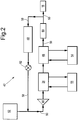
Figure 2 is a schematic layout of a re-circulated fuel circuit used for cooling the engine's starter/generator. -
Figure 1 shows a ducted fan gas turbine engine generally indicated at 10 and comprising three main rotational shafts, however, the present invention is equally applicable to an engine having any number of shafts. Thisengine 10 has a principal androtational axis 11. Theengine 10 comprises acore engine 9 having, in axial flow series, anair intake 12, a propulsive fan 13, anintermediate pressure compressor 14, a high-pressure compressor 15,combustion equipment 16, a high-pressure turbine 17, andintermediate pressure turbine 18, a low-pressure turbine 19 and acore exhaust nozzle 20. Anacelle 21 generally surrounds theengine 10 and defines both theintake 12 and abypass exhaust nozzle 22. - The
gas turbine engine 10 works in the conventional manner so that air entering theintake 11 is accelerated by the fan 13 to produce two air flows: a first air flow into theintermediate pressure compressor 14 and a second air flow which passes through abypass duct 23 to provide propulsive thrust. Theintermediate pressure compressor 14 compresses the air flow directed into it before delivering that air to thehigh pressure compressor 15 where further compression takes place. - The compressed air exhausted from the high-
pressure compressor 15 is directed into thecombustion equipment 16 where it is mixed with fuel and the mixture combusted. The resultant hot combustion products then expand through, and thereby drive the high, intermediate and low-pressure turbines nozzle 20 to provide additional propulsive thrust. The high, intermediate and low-pressure turbines intermediate pressure compressors - The fan 13 is circumferentially surrounded by a structural member in the form of a
fan casing 26, which is supported by an annular array ofoutlet guide vanes 27. - The
engine 10 further comprises a gearbox/generator assembly 28 used for engine start up and for generating electricity once the engine has been started and working in convention fashion. The starter/generator is a variable frequency starter / generator (VFSG) as known in the art. The generated electricity is used for engine and associated aircraft electrical accessories as well known in the art. The gearbox/generator assembly 28 is drivingly connected to the high-pressure shaft 24, however, in other embodiments may be driven by any one or more of the shafts. In this embodiment, the gearbox/generator assembly 28 comprises aninternal gearbox 29 connecting afirst drive shaft 30 to the high-pressure shaft 24, anintermediate gearbox 31 connecting thefirst drive shaft 30 to asecond drive shaft 32 and anexternal gearbox 33 drivingly connected to thesecond drive shaft 32. Theexternal gearbox 33 is drivingly connected to a starter/generator 34 that is capable of the aforesaid engine operation. The starter/generator 34 andexternal gearbox 33 are housed within thenacelle 21, but may be positioned on the core engine, as opposed to the fan casing. Thefirst drive shaft 30,intermediate gearbox 31 and thesecond drive shaft 32 are housed within a bypassduct splitter fairing 40. - Referring now to
Figure 2 theengine 10 further comprises a re-circulatedfuel circuit 42 used for cooling the starter /generator 34. The re-circulatedfuel circuit 42 comprises apump 44, a first fuel and oil heat exchanger 56 (FOHE), a second fuel andoil heat exchanger 46 and afuel accumulator 48. The re-circulatedfuel circuit 42 is situated on themain fuel line 50 between the mainaircraft fuel tank 52, usually housed within the aircraft's fuselage or wing, and a fuel injector or thecombustion equipment 16. Note that there-circulation fuel circuit 42 is part of theengine 10 and not the aircraft. - Inclusion of certain engine units in the fuel circuit is to increase the thermal capacity, e.g., the addition of a second FOHE 46 and
filter 60. - The second FOHE 46 is fluidly connected to an
engine oil circuit 54 and the first FOHE 56 is fluidly connected to a starter /generator 34. The oil in the starter circuit is self-contained; it is not connected to the engine oil system. A small oil sump (not shown) is provided in the starter /generator 34. - A
filter 60 is positioned between the second FOHE 46 and thecombustor 16. A shut offvalve 62 is positioned downstream of thefuel accumulator 48 to stop fuel return flow during normal engine running. - In use, the
circuit 42 re-circulates fuel via thepump 44, through the variable frequency starter / generator FOHE 56. The FOHE 56 dissipates heat from the VFSG 34, which is in contrast to the conventional practice of sending the fuel back toaircraft fuel tank 52. - The
accumulator 48, situated on afuel return line 58 is used to control the volume of fuel in thecircuit 42 and increases the fuel's thermal capacity to remove the limitations of the conventional static thermal sink (i.e. themain fuel tank 52 in a conventional engine/aircraft). Theaccumulator 48 will be filled with fuel before or during the engine start. When the engine has successfully achieved a start, the fuel in theaccumulator 48 will be emptied and sent back to the engine fuel line to be consumed by theengine combustor 16 during engine running. The accumulator could be a dedicated unit or a modified existing unit on engine, e.g., the fuel drain tank. A mechanical means or a modified existing unit on engine, such as the ejector pump in fuel drain tank, may be employed to change the effective volume of theaccumulator 48. The mechanical means, such as a piston, may be powered by electrical, pneumatic or hydraulic devices or stored mechanical energy, such as a spring, could be used for this purpose. - Advantageously, the present invention removes the need of returning fuel back to
aircraft fuel tank 52 during engine start up and hence there is no disturbance on fuel balance in aircraft'sfuel tanks 52 and there are no fuel contamination issues. - Addition of the
fuel accumulator 48 removes the limitation of the aircraft fuel tank as a static heat sink. - The
accumulator 48 minimises the amount of fuel stored onengine 10. The accumulator is either evacuated by such means as an ejector pump, where the accumulated fuel is transferred into the main fuel lines and is consumed in the engine combustor or has its effective volume reduced mechanically to expel the contents into the fuel system, also to be consumed in the engine combustor.
Claims (8)
- A gas turbine engine (10) comprising a turbine (17) and a compressor (15) connected via a shaft (24), a main fuel supply line (50) for supplying fuel to a combustor (16) that is positioned to release expanding hot gases to the turbine (17), the engine (10) further comprises a first fuel and oil heat exchanger (56) associated with an engine starter/generator (34) that is connected to the shaft (24) via a gearbox assembly (28), the engine (10) is characterised by a re-circulating fuel circuit (42) positioned on the main fuel supply line (50) and comprising a second fuel/oil heat exchanger (46) and a fuel accumulator (48), the re-circulating fuel circuit (42) cools the oil in the starter/generator (34) via the first fuel and oil heat exchanger (56).
- A gas turbine engine (10) as claimed in claim 1 wherein the second fuel/oil heat exchanger (46) is fluidly connected to an engine oil circuit (54).
- A gas turbine engine (10) as claimed in any one of claims 1-2 wherein the first fuel/oil heater exchanger (56) is fluidly connected to the starter/generator (34).
- A gas turbine engine (10) as claimed in any one of claims 1-3 wherein the circuit (42) comprises a fuel filter (60).
- A gas turbine engine (10) as claimed in claim 4 wherein fuel filter (60) is positioned between the second fuel/oil heat exchanger (46) and the combustor (16).
- A gas turbine engine (10) as claimed in any one of claims 1-5 wherein the circuit (42) comprises a shut off valve (62) that is provided to stop fuel return flow during normal engine running.
- A method of operating a gas turbine engine (10) comprising a turbine (17) and a compressor (15) connected via a shaft (24), a main fuel supply line (50) for supplying fuel to a combustor (16) that is positioned to release expanding hot gases to the turbine (17), the engine (10) further comprises a starter/generator (56) connected to the shaft (24) via a gearbox assembly (28), the method is characterised the step of during engine start up (10) fuel is circulated in a re-circulating fuel circuit (42) positioned on the main fuel supply line (50) and which comprises a first fuel/oil heat exchanger (56), for cooling the oil in the starter/generator oil circuit, and a fuel accumulator (48).
- A method of operating a gas turbine engine (10) as claimed in claim 8 wherein a further step comprises supplying the cooled fuel to the starter/generator (34) for cooling.
Applications Claiming Priority (1)
| Application Number | Priority Date | Filing Date | Title |
|---|---|---|---|
| GBGB0707319.0A GB0707319D0 (en) | 2007-04-17 | 2007-04-17 | Apparatus and method of operating a gas turbine engine at start-up |
Publications (3)
| Publication Number | Publication Date |
|---|---|
| EP1983174A2 EP1983174A2 (en) | 2008-10-22 |
| EP1983174A3 EP1983174A3 (en) | 2012-12-19 |
| EP1983174B1 true EP1983174B1 (en) | 2018-01-03 |
Family
ID=38116813
Family Applications (1)
| Application Number | Title | Priority Date | Filing Date |
|---|---|---|---|
| EP08250900.1A Expired - Fee Related EP1983174B1 (en) | 2007-04-17 | 2008-03-15 | Apparatus and method of operating a gas turbine engine at start-up |
Country Status (3)
| Country | Link |
|---|---|
| US (1) | US8132398B2 (en) |
| EP (1) | EP1983174B1 (en) |
| GB (1) | GB0707319D0 (en) |
Families Citing this family (30)
| Publication number | Priority date | Publication date | Assignee | Title |
|---|---|---|---|---|
| US7997085B2 (en) * | 2006-09-27 | 2011-08-16 | General Electric Company | Gas turbine engine assembly and method of assembling same |
| RU2353787C1 (en) * | 2007-09-06 | 2009-04-27 | Открытое акционерное общество "Российские железные дороги" (ОАО "РЖД") | Gas-turbine plant |
| FR2942271B1 (en) * | 2009-02-16 | 2011-05-13 | Hispano Suiza Sa | AERONAUTICAL MOTOR WITH COOLING OF AN ELECTRIC START-UP DEVICE |
| US20110283708A1 (en) * | 2010-05-24 | 2011-11-24 | Rigo Rodriguez | Landfill gas utilization |
| US9382013B2 (en) | 2011-11-04 | 2016-07-05 | The Boeing Company | Variably extending heat transfer devices |
| US9140194B2 (en) | 2012-01-11 | 2015-09-22 | Honeywell International Inc. | Gas turbine engine starter-generator with integrated lube oil scavenge functionality |
| US20130232941A1 (en) * | 2012-03-07 | 2013-09-12 | Ge Aviation Systems Llc | Apparatus for extracting input power from the low pressure spool of a turbine engine |
| JP5568596B2 (en) * | 2012-05-30 | 2014-08-06 | 川崎重工業株式会社 | Aircraft engine gearbox integrated power generator |
| US20140165586A1 (en) * | 2012-12-17 | 2014-06-19 | United Technologies Corporation | Turbine start method |
| WO2014130650A1 (en) * | 2013-02-20 | 2014-08-28 | United Technologies Corporation | Self-purging fuel injector system for a gas turbine engine |
| ES2758081T3 (en) * | 2013-02-21 | 2020-05-04 | United Technologies Corp | Removal of inhomogeneous ice from a fuel system |
| US9823030B2 (en) * | 2013-08-14 | 2017-11-21 | Hamilton Sundstrand Corporation | Heated bypass valve for heat exchanger |
| WO2015094903A1 (en) * | 2013-12-16 | 2015-06-25 | United Technologies Corporation | Ceramic coating for heated fuel filter |
| WO2015130356A2 (en) * | 2013-12-16 | 2015-09-03 | United Technologies Corporation | Ice tolerant gas turbine fuel systems |
| US20160311551A1 (en) * | 2015-03-19 | 2016-10-27 | Hamilton Sundstrand Corporation | Engine proximate nitrogen generation system for an aircraft |
| US10287909B2 (en) * | 2015-05-29 | 2019-05-14 | Pratt & Whitney Canada Corp. | Method and kit for preserving a fuel system of an aircraft engine |
| US10215097B2 (en) | 2015-12-08 | 2019-02-26 | General Electric Company | Thermal management system |
| US11028812B2 (en) * | 2016-07-27 | 2021-06-08 | Astronics Advanced Electronic Systems Corp. | Integrated brushless starter generator |
| US10746181B2 (en) * | 2016-08-22 | 2020-08-18 | Raytheon Technologies Corporation | Variable speed boost compressor for gas turbine engine cooling air supply |
| US20220195927A1 (en) * | 2020-12-21 | 2022-06-23 | General Electric Company | Regenerative fuel heating system |
| US11492970B2 (en) | 2020-12-21 | 2022-11-08 | General Electric Company | Thermal management system with fuel cooling |
| US11560239B2 (en) | 2020-12-21 | 2023-01-24 | General Electric Company | Regenerative thermal management system |
| US11773782B2 (en) * | 2020-12-23 | 2023-10-03 | Rtx Corporation | Gas turbine engines having cryogenic fuel systems |
| FR3120114A1 (en) * | 2021-02-25 | 2022-08-26 | Airbus Operations | AIRCRAFT WITH AN ENGINE AND A DIHYDROGEN-BASED COOLING SYSTEM |
| US11761344B1 (en) | 2022-04-19 | 2023-09-19 | General Electric Company | Thermal management system |
| US11702985B1 (en) | 2022-04-19 | 2023-07-18 | General Electric Company | Thermal management system |
| US11873768B1 (en) | 2022-09-16 | 2024-01-16 | General Electric Company | Hydrogen fuel system for a gas turbine engine |
| US11905884B1 (en) | 2022-09-16 | 2024-02-20 | General Electric Company | Hydrogen fuel system for a gas turbine engine |
| US11898495B1 (en) | 2022-09-16 | 2024-02-13 | General Electric Company | Hydrogen fuel system for a gas turbine engine |
| GB202219390D0 (en) * | 2022-12-21 | 2023-02-01 | Rolls Royce Plc | Gas turbine operation |
Family Cites Families (11)
| Publication number | Priority date | Publication date | Assignee | Title |
|---|---|---|---|---|
| US3766734A (en) * | 1972-03-01 | 1973-10-23 | Gen Electric | Dual fuel control system for a gas turbine |
| US3878678A (en) * | 1973-08-20 | 1975-04-22 | Gen Motors Corp | Gas turbine fuel system |
| US4590796A (en) * | 1985-01-23 | 1986-05-27 | Floscan Instrument Co., Inc. | Apparatus and method for pulsation damping and flow measurement in liquid fuel system |
| US4696156A (en) * | 1986-06-03 | 1987-09-29 | United Technologies Corporation | Fuel and oil heat management system for a gas turbine engine |
| US5177951A (en) | 1989-04-06 | 1993-01-12 | Rolls-Royce Plc | Method for management of heat generated by aircraft gas turbine installations |
| GB9606546D0 (en) * | 1996-03-28 | 1996-06-05 | Rolls Royce Plc | Gas turbine engine system |
| US6298833B1 (en) * | 2000-04-07 | 2001-10-09 | Westport Research Inc. | Fluid seal apparatus and method for dynamically controlling sealing-fluid pressure |
| US6651441B2 (en) * | 2002-01-22 | 2003-11-25 | Hamilton Sundstrand | Fluid flow system for a gas turbine engine |
| EP1683947A3 (en) * | 2005-01-21 | 2007-04-18 | Honeywell International Inc. | Method to control starter/generator cooling fuel flow during engine starting |
| US7805947B2 (en) * | 2005-05-19 | 2010-10-05 | Djamal Moulebhar | Aircraft with disengageable engine and auxiliary power unit components |
| US7908840B2 (en) * | 2006-11-29 | 2011-03-22 | United Technologies Corporation | Turbine engine with integrated generator having shared lubrication system |
-
2007
- 2007-04-17 GB GBGB0707319.0A patent/GB0707319D0/en not_active Ceased
-
2008
- 2008-03-15 EP EP08250900.1A patent/EP1983174B1/en not_active Expired - Fee Related
- 2008-03-24 US US12/053,739 patent/US8132398B2/en not_active Expired - Fee Related
Non-Patent Citations (1)
| Title |
|---|
| None * |
Also Published As
| Publication number | Publication date |
|---|---|
| GB0707319D0 (en) | 2007-05-23 |
| EP1983174A2 (en) | 2008-10-22 |
| EP1983174A3 (en) | 2012-12-19 |
| US8132398B2 (en) | 2012-03-13 |
| US20080250792A1 (en) | 2008-10-16 |
Similar Documents
| Publication | Publication Date | Title |
|---|---|---|
| EP1983174B1 (en) | Apparatus and method of operating a gas turbine engine at start-up | |
| US11815024B2 (en) | Thermal management system | |
| US9945247B2 (en) | Gas turbine engine anti-icing system | |
| US11174789B2 (en) | Air cycle assembly for a gas turbine engine assembly | |
| US8602717B2 (en) | Compression system for turbomachine heat exchanger | |
| CA2931493C (en) | Aircraft environmental control system | |
| US10125692B2 (en) | Gas turbine engine system having a disengageable electric machine | |
| US5845483A (en) | Windmill engine starting system with fluid driven motor and pump | |
| EP2584173B1 (en) | Gas Turbine Engine | |
| EP2584174B1 (en) | Windmill operation of a gas turbine engine | |
| EP3260688B1 (en) | Compartment cooling for a gas turbine engine | |
| EP3236051A1 (en) | Oil-free gas turbine engine | |
| US20090289456A1 (en) | Gas turbine engine apparatus | |
| JP2017030728A (en) | Cooling system | |
| EP3321490B1 (en) | Turbo-generator based bleed air system | |
| US8966876B2 (en) | Controllable speed windmill operation of a gas turbine engine through low spool power extraction | |
| EP1647675A1 (en) | Adequate oil supply for an aeroengine oil tank system | |
| US20110296846A1 (en) | Aeronautical engine with cooling of an electric starting device | |
| EP3848568A1 (en) | Oil supply device for aircraft gas turbine | |
| EP4224000A1 (en) | Multiple turboexpander system having selective coupler | |
| EP4367373A2 (en) | Turbine engines having hydrogen fuel systems | |
| EP4303416A1 (en) | Turbo expanders for turbine engines having hydrogen fuel systems |
Legal Events
| Date | Code | Title | Description |
|---|---|---|---|
| PUAI | Public reference made under article 153(3) epc to a published international application that has entered the european phase |
Free format text: ORIGINAL CODE: 0009012 |
|
| AK | Designated contracting states |
Kind code of ref document: A2 Designated state(s): AT BE BG CH CY CZ DE DK EE ES FI FR GB GR HR HU IE IS IT LI LT LU LV MC MT NL NO PL PT RO SE SI SK TR |
|
| AX | Request for extension of the european patent |
Extension state: AL BA MK RS |
|
| PUAL | Search report despatched |
Free format text: ORIGINAL CODE: 0009013 |
|
| AK | Designated contracting states |
Kind code of ref document: A3 Designated state(s): AT BE BG CH CY CZ DE DK EE ES FI FR GB GR HR HU IE IS IT LI LT LU LV MC MT NL NO PL PT RO SE SI SK TR |
|
| AX | Request for extension of the european patent |
Extension state: AL BA MK RS |
|
| RIC1 | Information provided on ipc code assigned before grant |
Ipc: F02C 7/268 20060101ALI20121115BHEP Ipc: F02C 7/12 20060101AFI20121115BHEP |
|
| 17P | Request for examination filed |
Effective date: 20130614 |
|
| AKX | Designation fees paid |
Designated state(s): DE FR GB |
|
| RAP1 | Party data changed (applicant data changed or rights of an application transferred) |
Owner name: ROLLS-ROYCE PLC |
|
| GRAP | Despatch of communication of intention to grant a patent |
Free format text: ORIGINAL CODE: EPIDOSNIGR1 |
|
| STAA | Information on the status of an ep patent application or granted ep patent |
Free format text: STATUS: GRANT OF PATENT IS INTENDED |
|
| GRAS | Grant fee paid |
Free format text: ORIGINAL CODE: EPIDOSNIGR3 |
|
| GRAA | (expected) grant |
Free format text: ORIGINAL CODE: 0009210 |
|
| STAA | Information on the status of an ep patent application or granted ep patent |
Free format text: STATUS: THE PATENT HAS BEEN GRANTED |
|
| INTG | Intention to grant announced |
Effective date: 20171114 |
|
| AK | Designated contracting states |
Kind code of ref document: B1 Designated state(s): DE FR GB |
|
| REG | Reference to a national code |
Ref country code: GB Ref legal event code: FG4D |
|
| REG | Reference to a national code |
Ref country code: DE Ref legal event code: R096 Ref document number: 602008053571 Country of ref document: DE |
|
| REG | Reference to a national code |
Ref country code: FR Ref legal event code: PLFP Year of fee payment: 11 |
|
| REG | Reference to a national code |
Ref country code: DE Ref legal event code: R097 Ref document number: 602008053571 Country of ref document: DE |
|
| PLBE | No opposition filed within time limit |
Free format text: ORIGINAL CODE: 0009261 |
|
| STAA | Information on the status of an ep patent application or granted ep patent |
Free format text: STATUS: NO OPPOSITION FILED WITHIN TIME LIMIT |
|
| 26N | No opposition filed |
Effective date: 20181005 |
|
| PGFP | Annual fee paid to national office [announced via postgrant information from national office to epo] |
Ref country code: DE Payment date: 20200327 Year of fee payment: 13 Ref country code: GB Payment date: 20200327 Year of fee payment: 13 |
|
| PGFP | Annual fee paid to national office [announced via postgrant information from national office to epo] |
Ref country code: FR Payment date: 20200325 Year of fee payment: 13 |
|
| REG | Reference to a national code |
Ref country code: DE Ref legal event code: R119 Ref document number: 602008053571 Country of ref document: DE |
|
| GBPC | Gb: european patent ceased through non-payment of renewal fee |
Effective date: 20210315 |
|
| PG25 | Lapsed in a contracting state [announced via postgrant information from national office to epo] |
Ref country code: DE Free format text: LAPSE BECAUSE OF NON-PAYMENT OF DUE FEES Effective date: 20211001 Ref country code: FR Free format text: LAPSE BECAUSE OF NON-PAYMENT OF DUE FEES Effective date: 20210331 Ref country code: GB Free format text: LAPSE BECAUSE OF NON-PAYMENT OF DUE FEES Effective date: 20210315 |