EP1983111A1 - Formwork for limiting a diaphragm wall section, formwork element and method for manufacturing a diaphragm wall in the ground - Google Patents
Formwork for limiting a diaphragm wall section, formwork element and method for manufacturing a diaphragm wall in the ground Download PDFInfo
- Publication number
- EP1983111A1 EP1983111A1 EP07008140A EP07008140A EP1983111A1 EP 1983111 A1 EP1983111 A1 EP 1983111A1 EP 07008140 A EP07008140 A EP 07008140A EP 07008140 A EP07008140 A EP 07008140A EP 1983111 A1 EP1983111 A1 EP 1983111A1
- Authority
- EP
- European Patent Office
- Prior art keywords
- formwork
- shuttering
- parts
- element according
- formwork parts
- Prior art date
- Legal status (The legal status is an assumption and is not a legal conclusion. Google has not performed a legal analysis and makes no representation as to the accuracy of the status listed.)
- Withdrawn
Links
Images
Classifications
-
- E—FIXED CONSTRUCTIONS
- E02—HYDRAULIC ENGINEERING; FOUNDATIONS; SOIL SHIFTING
- E02D—FOUNDATIONS; EXCAVATIONS; EMBANKMENTS; UNDERGROUND OR UNDERWATER STRUCTURES
- E02D5/00—Bulkheads, piles, or other structural elements specially adapted to foundation engineering
- E02D5/18—Bulkheads or similar walls made solely of concrete in situ
- E02D5/182—Bulkheads or similar walls made solely of concrete in situ using formworks to separate sections
-
- E—FIXED CONSTRUCTIONS
- E04—BUILDING
- E04G—SCAFFOLDING; FORMS; SHUTTERING; BUILDING IMPLEMENTS OR AIDS, OR THEIR USE; HANDLING BUILDING MATERIALS ON THE SITE; REPAIRING, BREAKING-UP OR OTHER WORK ON EXISTING BUILDINGS
- E04G17/00—Connecting or other auxiliary members for forms, falsework structures, or shutterings
- E04G17/04—Connecting or fastening means for metallic forming or stiffening elements, e.g. for connecting metallic elements to non-metallic elements
-
- E—FIXED CONSTRUCTIONS
- E02—HYDRAULIC ENGINEERING; FOUNDATIONS; SOIL SHIFTING
- E02D—FOUNDATIONS; EXCAVATIONS; EMBANKMENTS; UNDERGROUND OR UNDERWATER STRUCTURES
- E02D5/00—Bulkheads, piles, or other structural elements specially adapted to foundation engineering
- E02D5/18—Bulkheads or similar walls made solely of concrete in situ
- E02D5/185—Bulkheads or similar walls made solely of concrete in situ with flexible joint members between sections
Definitions
- the present invention in a first aspect relates to a formwork element for defining a slot wall portion of a slot wall.
- the invention relates to a formwork part, which is particularly suitable for forming a formwork element according to the invention.
- the invention relates to a method for producing a slot wall in the ground, in which with a slot wall device, in particular a trench cutter, adjacent slot wall sections are formed in the ground, wherein at least one slot wall portion is limited by an introduced formwork element.
- a generic formwork element and a generic method are, for example DE 90 01 679 U1 known.
- shuttering elements to be concreted sections of a slot wall, for example steel shutters.
- the width or the diameter of such formwork elements corresponds to the thickness of the diaphragm wall.
- After the setting of the concrete such formwork elements must be removed, for example, be pulled over the hydraulic devices vertically upwards from the working joint. Since it is difficult to determine the most favorable for the extraction of the concrete setting time, there are often situations in which the concrete is either not yet sufficiently hardened or already too hard. In the first case break when pulling the formwork elements parts of the freshly concreted diaphragm wall and in the second case, the extraction of the formwork elements is considerably more difficult and is sometimes even impossible.
- prefabricated elements are used in the prior art when parking slot wall sections, which remain after concreting the corresponding slot wall sections in the ground.
- Such prefabricated elements can be made for example of steel or concrete.
- Such components are extremely bulky due to their weight.
- formwork elements made of concrete that in order to avoid damage, they must be hardened very well, resulting in a very long storage life.
- such concrete formwork components must be cured for about four weeks due to the sensitivity of the concrete to tensile loads.
- the object of the invention is to provide a formwork element which is particularly easy to install. Furthermore, a method for producing a trench wall in the ground is to be specified, in which a limitation of a slot wall section in an unrestricted manner is possible.
- the formwork element of the abovementioned type includes a plurality of formwork parts which have a plate-shaped base body, in particular of concrete, and are connected to one another at their adjacent horizontal end faces.
- the formwork part according to the invention which is particularly suitable for forming a formwork element according to the invention, has a plate-shaped base body, in particular made of concrete, wherein on at least one horizontal end face of the base body, a connecting device for connecting a further formwork part is arranged.
- the formwork element is composed of individual formwork parts, which are successively introduced into the slot and connected to each other at their horizontal end faces.
- the formwork element no longer, as in the prior art, one piece but composed of several formwork parts or shuttering segments.
- a first significant advantage in this context is that these shuttering parts are much smaller, for example as formwork elements for very deep diaphragm walls. This results in considerable advantages in terms of the handling and processability of the formwork elements and formwork parts.
- the formwork parts according to the invention have suitable connection devices on their horizontal end faces so that individual formwork parts can be connected to one another.
- formwork parts are subjected to much lower loads during assembly and during movement and transporting before assembly because of their smaller size than a one-piece large formwork element. If the formwork parts are made of concrete, already significantly shorter curing times are sufficient. First tests have shown that with formwork parts with a length of about 6 m, the concrete has already hardened sufficiently after two days.
- slot walls with different depths can be divided with the same formwork parts. A preparation of formwork elements suitable for each required slot wall depth is therefore no longer necessary.
- the formwork parts can be made of any materials that have suitable properties in view of the permanent remaining in the slot wall.
- the formwork parts may be made of steel. But is particularly preferred if the main body of the formwork parts are made of concrete.
- the invention accordingly relates to a shuttering element for limiting a slot wall section, wherein the shuttering elements consist of individual sections which can be connected to one another via threaded rods.
- the front-side connecting surfaces can be designed as steel plates in order to ensure an axis-accurate connection of the individual parts and to allow the installation of sealing elements.
- a vertical sealing tape or joint sealing tape can be performed at joints of Abschalelementabête overlapping and connected to each other.
- the Abschaletti can be adjusted perpendicular to the slot after a short storage time with sufficient strength of the concrete, where they can be initially held on the baffle by means of a transverse bore axis to connect to the next formwork part and to seal the joints.
- a Abschalelement is provided which can remain in the slot wall and still requires a very short production time until the concrete has the necessary strength.
- the Abschalelement invention ensures that at low slot wall width and large slot depth, the Abschalelement not, as usual in steel planks, twisted and thus a sufficient seal can not be ensured.
- these connecting devices may each comprise screw connections.
- suitable recesses may be formed in the shape of the concrete base body.
- the diaphragm wall For many applications, such as having to draw in diaphragm walls below the groundwater level, it is necessary for the diaphragm wall to be watertight as a whole. For this purpose, it must be ensured in particular that the transition region between the already hardened formwork element according to the invention and the only thereafter curing concrete in the adjacent slot wall section is sealed.
- a joint sealing strip can be arranged along at least one longitudinal side of the formwork parts, which is directed to delimiting the slot wall section.
- the joint sealing strips of adjacent formwork parts are connected by means of connecting pieces tightly together.
- these connecting pieces may be formed as metal brackets, which may be in particular metal plates, which are arranged on opposite sides of the joint sealing strips and suitably connected to each other, for example screwed together.
- the area in which the horizontal end faces of two adjoining shuttering parts abut each other must also be sealed.
- the areas between adjacent formwork parts, in particular also any existing connecting pieces be filled with sealing compound. This can, for example, shortly before two formwork parts are placed on each other and pulled together, are applied to the corresponding end faces.
- a seal for sealing against a subsequent formwork part is present on at least one horizontal end face of the formwork part.
- such a seal may be formed of a steel plate and a rubber plate mounted thereon.
- the steel plate can be welded to a steel reinforcement of the concrete body.
- a holding device in particular a horizontal opening, is also present in the formwork part according to the invention.
- the handling ie the conveying and manipulating the formwork part according to the invention is simplified.
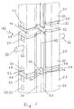
- Formwork element 10 shown in the assembly stage is composed of a plurality of formwork parts 20, of which in Fig. 1 a complete and the upwardly and downwardly adjacent formwork parts are partially shown.
- the length of a formwork part 20 is about 6 m.
- the formwork members 20 each include a base body 30 having a substantially wall or plate-like shape.
- connecting means 50 are provided for connecting the respective following formwork part 20.
- it is the connection means 50 to screw, which are not shown in detail and in recesses 56 in the concrete body 30th are arranged.
- the recesses 56 are bounded on the end faces 32 of the formwork parts 20 by metal plates 58.
- the outer contour of these metal plates 58 corresponds to the profile of the base body 30.
- the metal plates 58 are already welded to a steel reinforcement of the respective base body 30.
- the metal plates 58 are used in particular for fastening further sealing devices, for example rubber plates.
- these have a horizontal opening 62, which can serve as a holding device 60.
- a schematically illustrated holding rod 64 is inserted into the opening 62, which can be used for transporting and manipulating the formwork part 20.
- a joint sealing tape 40 is present on the formwork parts on the longitudinal sides 34, which is encapsulated in the base body 30.
- Fig. 1 shown schematically, connected with connectors 44 tightly together.
- the connecting pieces 44 are metal clips 46, which are connected to one another by suitable fastening means, for example screwed connections.
- a sealing compound for example before tightening the connecting devices 50.
- the formwork parts 20 are provided on the horizontal end faces 32 with seals.
- Seals may in particular be a rubber plate fixed to the metal plates 58, for example bolted to the metal plates 58.
- a metal plate 58 is provided only on a formwork part 20 on its horizontal end face 32.
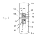
- FIG. 2 a detail of a connection region between two adjoining shuttering parts 20 with basic bodies 30 is shown.
- the connecting devices 50 shown there in further details initially have a substantially cuboid metal box 57, which is welded to the respective metal plates 58 and also to an inner reinforcing basket of the main body 30.
- a receptacle 56 formed by this metal box 57 an externally accessible threaded rod 90 is received with nuts 92. This threaded rod is through the in Fig. 1 shown openings 54 pushed through.
- the present invention provides a novel shuttering element constructed from a plurality of shuttering parts, as well as a novel method for producing a slot wall in the floor, which allows considerable simplifications for the creation of individual slot wall sections.
Abstract
Description
Die vorliegende Erfindung bezieht sich in einem ersten Aspekt auf ein Schalungselement zum Begrenzen eines Schlitzwandabschnitts einer Schlitzwand.The present invention in a first aspect relates to a formwork element for defining a slot wall portion of a slot wall.
In einem weiteren Gesichtspunkt betrifft die Erfindung ein Schalungsteil, welches insbesondere zum Bilden eines erfindungsgemäßen Schalungselements geeignet ist.In a further aspect, the invention relates to a formwork part, which is particularly suitable for forming a formwork element according to the invention.
Schließlich bezieht sich die Erfindung auf ein Verfahren zum Herstellen einer Schlitzwand im Boden, bei dem mit einem Schlitzwandgerät, insbesondere einer Schlitzwandfräse, nebeneinander liegende Schlitzwandabschnitte im Boden gebildet werden, wobei zumindest ein Schlitzwandabschnitt durch ein eingebrachtes Schalungselement begrenzt wird.Finally, the invention relates to a method for producing a slot wall in the ground, in which with a slot wall device, in particular a trench cutter, adjacent slot wall sections are formed in the ground, wherein at least one slot wall portion is limited by an introduced formwork element.
Ein gattungsgemäßes Schalungselement und ein gattungsgemäßes Verfahren sind beispielsweise aus
Es ist bekannt, beim Abstellen von zu betonierenden Abschnitten einer Schlitzwand Schalungselemente, beispielsweise Abschalrohre aus Stahl, zu verwenden. Die Breite oder der Durchmesser solcher Schalungselemente, die vor dem Betonieren in die Arbeitsfuge abgesenkt werden, entspricht dabei der Dicke der Schlitzwand. Nach dem Abbinden des Betons müssen solche Schalungselemente entfernt werden, beispielsweise über hydraulische Vorrichtungen vertikal nach oben aus der Arbeitsfuge gezogen werden. Da es schwierig ist, den für das Herausziehen günstigsten Abbindezeitpunkt des Betons zu bestimmen, kommt es häufig zu Situationen, bei denen der Beton entweder noch nicht ausreichend abgebunden oder bereits zu hart ist. Im ersten Fall brechen beim Ziehen der Schalungselemente Teile der frisch betonierten Schlitzwand ein und im zweiten Fall wird das Herausziehen der Schalungselemente erheblich erschwert und ist sogar manchmal unmöglich.It is known to use shuttering elements to be concreted sections of a slot wall, for example steel shutters. The width or the diameter of such formwork elements, which are lowered before concreting into the working joint, corresponds to the thickness of the diaphragm wall. After the setting of the concrete such formwork elements must be removed, for example, be pulled over the hydraulic devices vertically upwards from the working joint. Since it is difficult to determine the most favorable for the extraction of the concrete setting time, there are often situations in which the concrete is either not yet sufficiently hardened or already too hard. In the first case break when pulling the formwork elements parts of the freshly concreted diaphragm wall and in the second case, the extraction of the formwork elements is considerably more difficult and is sometimes even impossible.
Um diese Schwierigkeiten zu vermeiden, werden im Stand der Technik auch Fertigteilelemente beim Abstellen von Schlitzwandabschnitten verwendet, welche nach dem Betonieren der entsprechenden Schlitzwandabschnitte im Boden verbleiben. Solche Fertigteilelemente können beispielsweise aus Stahl oder auch aus Beton gefertigt sein. Bei größeren Schlitzwandtiefen sind solche Komponenten aufgrund ihres Gewichts jedoch außerordentlich unhandlich. Hinzu kommt im Fall von Schalungselementen aus Beton, dass diese, um Beschädigungen zu vermeiden, sehr gut ausgehärtet sein müssen, woraus sich eine sehr hohe Lagerzeit ergibt. Typischerweise müssen solche Schalungskomponenten aus Beton aufgrund der Empfindlichkeit des Betons gegenüber Zugbelastungen etwa vier Wochen ausgehärtet sein.In order to avoid these difficulties, prefabricated elements are used in the prior art when parking slot wall sections, which remain after concreting the corresponding slot wall sections in the ground. Such prefabricated elements can be made for example of steel or concrete. For larger slot wall depths, however, such components are extremely bulky due to their weight. In addition, in the case of formwork elements made of concrete, that in order to avoid damage, they must be hardened very well, resulting in a very long storage life. Typically, such concrete formwork components must be cured for about four weeks due to the sensitivity of the concrete to tensile loads.
Aufgabe der Erfindung ist, ein Schalungselement zu schaffen, welches besonders einfach zu installieren ist. Weiterhin soll ein Verfahren zum Herstellen einer Schlitzwand im Boden angegeben werden, bei dem eine Begrenzung eines Schlitzwandabschnitts in unaufwändiger Weise möglich ist. The object of the invention is to provide a formwork element which is particularly easy to install. Furthermore, a method for producing a trench wall in the ground is to be specified, in which a limitation of a slot wall section in an unrestricted manner is possible.
Diese Aufgabe wird in einem ersten Gesichtspunkt der Erfindung durch das Schalungselement mit den Merkmalen des Anspruchs 1 und das Schalungsteil mit den Merkmalen des Anspruchs 8 gelöst.This object is achieved in a first aspect of the invention by the formwork element with the features of claim 1 and the formwork part with the features of claim 8.
In verfahrensmäßiger Hinsicht wird die Aufgabe durch das Verfahren mit den Merkmalen des Anspruchs 12 gelöst.In procedural terms, the object is achieved by the method having the features of claim 12.
Bevorzugte Ausführungsbeispiele des erfindungsgemäßen Schalungselements und des erfindungsgemäßen Schalungsteils sind Gegenstand der abhängigen Ansprüche.Preferred embodiments of the formwork element according to the invention and the formwork part according to the invention are the subject of the dependent claims.
Das Schalungselement der oben genannten Art beinhaltet erfindungsgemäß eine Mehrzahl von Schalungsteilen, die einen plattenförmigen Grundkörper, insbesondere aus Beton, aufweisen und an ihren angrenzenden horizontalen Stirnseiten miteinander verbunden sind.According to the invention, the formwork element of the abovementioned type includes a plurality of formwork parts which have a plate-shaped base body, in particular of concrete, and are connected to one another at their adjacent horizontal end faces.
Das erfindungsgemäße Schalungsteil, welches insbesondere zum Bilden eines erfindungsgemäßen Schalungselements geeignet ist, weist einen plattenförmigen Grundkörper, insbesondere aus Beton, auf, wobei an mindestens einer horizontalen Stirnseite des Grundkörpers eine Verbindungseinrichtung zum Anschluss eines weiteren Schalungsteils angeordnet ist.The formwork part according to the invention, which is particularly suitable for forming a formwork element according to the invention, has a plate-shaped base body, in particular made of concrete, wherein on at least one horizontal end face of the base body, a connecting device for connecting a further formwork part is arranged.
Das Verfahren der oben genannten Art ist erfindungsgemäß dadurch weitergebildet, dass das Schalungselement aus einzelnen Schalungsteilen zusammengesetzt wird, welche nacheinander in den Schlitz eingebracht und an ihren horizontalen Stirnseiten miteinander verbunden werden.The method of the above type according to the invention further developed in that the formwork element is composed of individual formwork parts, which are successively introduced into the slot and connected to each other at their horizontal end faces.
Als Kerngedanke der Erfindung kann angesehen werden, das Schalungselement nicht mehr, wie im Stand der Technik, einteilig sondern aus mehreren Schalungsteilen oder Schalungssegmenten zusammenzusetzen.As a core idea of the invention can be considered, the formwork element no longer, as in the prior art, one piece but composed of several formwork parts or shuttering segments.
Ein erster wesentlicher Vorteil besteht in diesem Zusammenhang darin, dass diese Schalungsteile viel kleiner sind, beispielsweise als Schalungselemente für sehr tiefe Schlitzwände. Hieraus ergeben sich erhebliche Vorteile im Hinblick auf die Handhabbarkeit und Verarbeitbarkeit der Schalungselemente und Schalungsteile.A first significant advantage in this context is that these shuttering parts are much smaller, for example as formwork elements for very deep diaphragm walls. This results in considerable advantages in terms of the handling and processability of the formwork elements and formwork parts.
Die erfindungsgemäßen Schalungsteile weisen gemäß einem weiteren Kerngedanken der Erfindung an ihren horizontalen Stirnseiten geeignete Verbindungseinrichtungen auf, damit einzelne Schalungsteile miteinander verbunden werden können.According to a further aspect of the invention, the formwork parts according to the invention have suitable connection devices on their horizontal end faces so that individual formwork parts can be connected to one another.
Ein weiterer Vorteil der Erfindung kann darin gesehen werden, dass die Schalungsteile beim Zusammenbau und beim Bewegen und Transportieren vor dem Zusammenbau aufgrund ihrer kleineren Größe erheblich geringeren Belastungen ausgesetzt sind als ein einstückiges großes Schalungselement. Wenn die Schalungsteile aus Beton gefertigt sind, sind bereits deutlich kürzere Aushärtungszeiten ausreichend. Erste Tests haben ergeben, dass bei Schalungsteilen mit einer Länge von etwa 6 m der Beton bereits nach zwei Tagen hinreichend ausgehärtet ist.Another advantage of the invention can be seen in the fact that the formwork parts are subjected to much lower loads during assembly and during movement and transporting before assembly because of their smaller size than a one-piece large formwork element. If the formwork parts are made of concrete, already significantly shorter curing times are sufficient. First tests have shown that with formwork parts with a length of about 6 m, the concrete has already hardened sufficiently after two days.
Ein Vorteil der Erfindung besteht schließlich darin, dass mit denselben Schalungsteilen Schlitzwände mit unterschiedlichen Tiefen abgeteilt werden können. Eine Anfertigung von Schalungselementen passend zur jeweils geforderten Schlitzwandtiefe ist deshalb nicht mehr erforderlich.Finally, it is an advantage of the invention that slot walls with different depths can be divided with the same formwork parts. A preparation of formwork elements suitable for each required slot wall depth is therefore no longer necessary.
Grundsätzlich können die Schalungsteile aus beliebigen Materialien gefertigt sein, die im Hinblick auf den dauernden Verbleib in der Schlitzwand geeignete Eigenschaften aufweisen. Beispielsweise können die Schalungsteile aus Stahl bestehen. Besonders bevorzugt ist aber, wenn die Grundkörper der Schalungsteile aus Beton gefertigt sind.Basically, the formwork parts can be made of any materials that have suitable properties in view of the permanent remaining in the slot wall. For example, the formwork parts may be made of steel. But is particularly preferred if the main body of the formwork parts are made of concrete.
Die Erfindung betrifft demgemäß ein Abschalelement zum Begrenzen eines Schlitzwandabschnitts, wobei die Abschalelemente aus einzelnen Abschnitten bestehen, die über Gewindestangen miteinander verbunden sein können. Die stirnseitigen Verbindungsflächen können dabei als Stahlplatten ausgebildet sein, um eine achsgenaue Verbindung der Einzelteile zu gewährleisten und den Einbau von Dichtelementen zu ermöglichen. Dabei kann auch ein senkrechtes Dichtungsband oder Fugendichtband an Stoßstellen der Abschalelementabschnitte überlappend ausgeführt werden und miteinander verbunden werden. Die Abschalelemente können nach kurzer Lagerzeit bei genügender Festigkeit des Betons senkrecht in den Schlitz eingestellt werden, wobei sie zunächst auf der Leitwand mit Hilfe einer durch eine Querbohrung gehenden Achse gehalten werden können, um eine Verbindung zum nächsten Schalungsteil herzustellen und um die Stoßstellen abzudichten.The invention accordingly relates to a shuttering element for limiting a slot wall section, wherein the shuttering elements consist of individual sections which can be connected to one another via threaded rods. The front-side connecting surfaces can be designed as steel plates in order to ensure an axis-accurate connection of the individual parts and to allow the installation of sealing elements. In this case, a vertical sealing tape or joint sealing tape can be performed at joints of Abschalelementabschnitte overlapping and connected to each other. The Abschalelemente can be adjusted perpendicular to the slot after a short storage time with sufficient strength of the concrete, where they can be initially held on the baffle by means of a transverse bore axis to connect to the next formwork part and to seal the joints.
Mit der Erfindung wird ein Abschalelement bereitgestellt, das in der Schlitzwand verbleiben kann und dennoch eine sehr geringe Herstelldauer benötigt, bis der Beton die notwendige Festigkeit besitzt. Außerdem wird durch das erfindungsgemäße Abschalelement sichergestellt, dass bei geringer Schlitzwandbreite und großer Schlitztiefe sich das Abschalelement nicht, wie bei Stahlbohlen üblich, verwindet und damit eine ausreichende Dichtung nicht sichergestellt werden kann.With the invention, a Abschalelement is provided which can remain in the slot wall and still requires a very short production time until the concrete has the necessary strength. In addition, it is ensured by the Abschalelement invention that at low slot wall width and large slot depth, the Abschalelement not, as usual in steel planks, twisted and thus a sufficient seal can not be ensured.
Insgesamt wird durch das erfindungsgemäße Schalungselement eine bessere und exaktere Dichtung bei geringerer Schlitzbreite ermöglicht. Das Abschalelement verbleibt im Schlitz und muss nicht, wie bei Stahlbohlen üblich, nach jeder Verwendung gereinigt werden.Overall, a better and more accurate seal with a smaller slot width is made possible by the formwork element according to the invention. The shuttering element remains in the slot and does not need to be cleaned after each use, as is common in steel planks.
Zweckmäßig sind im Bereich der Stirnseiten der Schalungsteile Verbindungseinrichtungen angeordnet, mit welchen die Schalungsteile fest miteinander verbindbar sind.Suitably, in the region of the end faces of the formwork parts connecting means are arranged, with which the formwork parts are firmly connected to each other.
Beispielsweise können diese Verbindungseinrichtungen jeweils Schraubverbindungen umfassen. Hierzu können in der Form des Betongrundkörpers geeignete Ausnehmungen gebildet sein. Durch die Verbindungseinrichtungen wird eine sichere mechanische Verbindung der Schalungsteile untereinander gewährleistet.For example, these connecting devices may each comprise screw connections. For this purpose, suitable recesses may be formed in the shape of the concrete base body. By connecting means a secure mechanical connection of the formwork parts is guaranteed to each other.
Für zahlreiche Anwendungen, beispielsweise wenn Schlitzwände unterhalb des Grundwasserspiegels eingezogen werden müssen, ist es erforderlich, dass die Schlitzwand als Ganzes wasserdicht ist. Hierzu ist insbesondere dafür zu sorgen, dass der Übergangsbereich zwischen dem bereits ausgehärteten erfindungsgemäßen Schalungselement und dem erst danach aushärtenden Beton im angrenzenden Schlitzwandabschnitt abgedichtet wird.For many applications, such as having to draw in diaphragm walls below the groundwater level, it is necessary for the diaphragm wall to be watertight as a whole. For this purpose, it must be ensured in particular that the transition region between the already hardened formwork element according to the invention and the only thereafter curing concrete in the adjacent slot wall section is sealed.
Hierzu kann entlang zumindest einer Längsseite der Schalungsteile, welche zum Begrenzen des Schlitzwandabschnitts gerichtet ist, ein Fugendichtband angeordnet sein.For this purpose, a joint sealing strip can be arranged along at least one longitudinal side of the formwork parts, which is directed to delimiting the slot wall section.
Um auch eine sichere Abdichtung des Bereichs, in dem die Fugendichtbänder von aneinander grenzenden Schalungsteilen aufeinander stoßen, zu gewährleisten, sind bevorzugt die Fugendichtbänder von angrenzenden und miteinander verbundenen Schalungsteilen mittels Verbindungsstücken dicht miteinander verbunden.In order to ensure a secure seal the area in which the joint sealing strips of adjacent formwork parts abut one another, preferably the joint sealing strips of adjacent and interconnected formwork parts are connected by means of connecting pieces tightly together.
Bei einer einfachen Variante können diese Verbindungsstücke als Metallklammern gebildet sein, wobei es sich insbesondere um Metallplatten handeln kann, die auf gegenüberliegenden Seiten der Fugendichtbänder angeordnet und miteinander geeignet verbunden, beispielsweise miteinander verschraubt sind.In a simple variant of these connecting pieces may be formed as metal brackets, which may be in particular metal plates, which are arranged on opposite sides of the joint sealing strips and suitably connected to each other, for example screwed together.
Schließlich muss, wenn die Schlitzwand insgesamt wasserdicht sein soll, auch der Bereich, in dem die horizontalen Stirnseiten von zwei aneinander angrenzenden Schalungsteilen aufeinander stoßen, abgedichtet werden. Hierzu können einerseits die Bereiche zwischen angrenzenden Schalungsteilen, insbesondere auch gegebenenfalls vorhandene Verbindungsstücke, mit Dichtmasse verfüllt sein. Diese kann beispielsweise kurz bevor zwei Schalungsteile aufeinander gesetzt und zusammengezogen werden, auf die entsprechenden Stirnflächen aufgebracht werden.Finally, if the trench wall as a whole is to be watertight, the area in which the horizontal end faces of two adjoining shuttering parts abut each other must also be sealed. For this purpose, on the one hand, the areas between adjacent formwork parts, in particular also any existing connecting pieces, be filled with sealing compound. This can, for example, shortly before two formwork parts are placed on each other and pulled together, are applied to the corresponding end faces.
Bei besonders bevorzugten Ausführungsvarianten ist aber an mindestens einer horizontalen Stirnseite des Schalungsteils eine Dichtung zur Abdichtung gegenüber einem sich anschließenden Schalungsteil vorhanden.In particularly preferred embodiments, however, a seal for sealing against a subsequent formwork part is present on at least one horizontal end face of the formwork part.
Beispielsweise kann eine solche Dichtung aus einer Stahlplatte und einer darauf befestigten Gummiplatte gebildet sein. Die Stahlplatte kann dabei mit einer Stahlarmierung des Betongrundkörpers verschweißt sein.For example, such a seal may be formed of a steel plate and a rubber plate mounted thereon. The steel plate can be welded to a steel reinforcement of the concrete body.
Bei einer weiteren besonders bevorzugten Variante ist bei dem erfindungsgemäßen Schalungsteil außerdem eine Halteeinrichtung, insbesondere ein horizontaler Durchbruch, vorhanden. Durch eine solche Halteeinrichtung wird die Handhabbarkeit, also das Befördern und Manipulieren, des erfindungsgemäßen Schalungsteils vereinfacht.In a further particularly preferred variant, a holding device, in particular a horizontal opening, is also present in the formwork part according to the invention. By such a holding device, the handling, ie the conveying and manipulating the formwork part according to the invention is simplified.
Weitere Vorteile und Merkmale der Erfindung werden nachstehend mit Bezug auf die beigefügte schematische Figur beschrieben. Hierin zeigen:
- Fig. 1
- ein Ausführungsbeispiel eines erfindungsgemäßen Schalungselementes mit mehreren erfindungsgemäßen Schalungsteilen; und
- Fig. 2
- ein Detail eines Verbindungsbereichs von zwei aneinander grenzenden Schalungsteilen.
- Fig. 1
- An embodiment of a formwork element according to the invention with a plurality of formwork parts according to the invention; and
- Fig. 2
- a detail of a connection region of two adjacent formwork parts.
Das in
Die Schalungsteile 20 umfassen jeweils einen Grundkörper 30 mit einer im Wesentlichen wand- oder plattenartigen Form. An horizontalen Stirnseiten 32 der Grundkörper 30 der Schalungsteile 20 sind erfindungsgemäß Verbindungseinrichtungen 50 vorhanden zum Anschluss des jeweils folgenden Schalungsteils 20. Im gezeigten Beispiel handelt es sich bei den Verbindungseinrichtungen 50 um Schraubverbindungen, die im Detail nicht dargestellt sind und die in Ausnehmungen 56 im Betongrundkörper 30 angeordnet sind. Durch Öffnungen 54 greifen die Schraubverbindungen zu den jeweils angrenzenden Schalungsteilen 20 durch. Die Ausnehmungen 56 werden an den Stirnseiten 32 der Schalungsteile 20 durch Metallplatten 58 begrenzt. Die Außenkontur dieser Metallplatten 58 entspricht dem Profil des Grundkörpers 30. Besonders bevorzugt sind die Metallplatten 58 bereits mit einer Stahlarmierung des jeweiligen Grundkörpers 30 verschweißt. Die Metallplatten 58 dienen insbesondere zum Befestigen von weiteren Dichteinrichtungen, beispielsweise Gummiplatten.The
Die beiden unteren Schalungsteile 20 in
Zum Tragen der Schalungsteile 20 weisen diese einen horizontalen Durchbruch 62 auf, der als Halteeinrichtung 60 dienen kann.To carry the
Beim mittleren Schalungsteil 20 ist in den Durchbruch 62 eine schematisch dargestellte Haltestange 64 eingeschoben, die zum Transportieren und zum Manipulieren des Schalungsteils 20 benutzt werden kann.In the
Um ein sicheres Abdichten der Fugen zwischen dem bereits ausgehärteten Beton der Schalungsteile 20 und dem noch auszuhärtenden Beton des betreffenden Schlitzwandabschnitts zu gewährleisten, ist an den Schalungsteilen an den Längsseiten 34 ein Fugendichtband 40 vorhanden, welches in dem Grundkörper 30 vergossen ist.In order to ensure a secure sealing of the joints between the already hardened concrete of the
Um außerdem auch an den Stellen, an denen die Fugendichtbänder 40 von aneinander angrenzenden Schalungsteilen 20 aufeinander stoßen, eine Abdichtung sicherzustellen, sind diese Bereiche, wie in
Zum Abdichten der Bereiche zwischen den horizontalen Stirnseiten 32 von aneinander angrenzenden Schalungsteilen 20 können diese Bereiche, zum Beispiel vor dem Festziehen der Verbindungseinrichtungen 50, mit einer Dichtungsmasse verfüllt werden. Besonders bevorzugt sind aber die Schalungsteile 20 an den horizontalen Stirnseiten 32 mit Dichtungen versehen. Bei diesen, in
Grundsätzlich ist es aber ausreichend, wenn nur an einem Schalungsteil 20 an dessen horizontaler Stirnseite 32 eine Metallplatte 58 vorgesehen ist.In principle, however, it is sufficient if a
In
Einander entsprechende Komponenten sind in
Mit der vorliegenden Erfindung werden ein neuartiges, aus einer Mehrzahl von Schalungsteilen aufgebautes Schalungselement sowie ein neuartiges Verfahren zum Herstellen einer Schlitzwand im Boden bereitgestellt, die erhebliche Vereinfachungen für das Erstellen von einzelnen Schlitzwandabschnitten ermöglichen.The present invention provides a novel shuttering element constructed from a plurality of shuttering parts, as well as a novel method for producing a slot wall in the floor, which allows considerable simplifications for the creation of individual slot wall sections.
Claims (12)
gekennzeichnet durch,
eine Mehrzahl von Schalungsteilen (20), die einen plattenförmigen Grundkörper (30), insbesondere aus Beton, aufweisen und an ihren angrenzenden horizontalen Stirnseiten (32) miteinander verbunden sind.Shuttering element for limiting a slot wall portion of a slot wall,
characterized by
a plurality of formwork members (20) having a plate-shaped base body (30), in particular made of concrete, and are connected to each other at their adjacent horizontal end faces (32).
dadurch gekennzeichnet,
dass im Bereich der Stirnseiten (32) der Schalungsteile (20) Verbindungseinrichtungen (50) angeordnet sind, mit welchen die Schalungsteile (20) fest miteinander verbindbar sind.Shuttering element according to claim 1,
characterized,
that in the region of the end faces (32) of the formwork parts (20) connecting means (50) are arranged, with which the formwork parts (20) are firmly connected to one another.
dadurch gekennzeichnet,
dass die Verbindungseinrichtungen (50) Schraubverbindungen umfassen.Shuttering element according to claim 2,
characterized,
in that the connecting devices (50) comprise threaded connections.
dadurch gekennzeichnet,
dass entlang zumindest einer Längsseite (34) der Schalungsteile (20), welche zum begrenzenden Schlitzwandabschnitt gerichtet ist, ein Fugendichtband (40) angeordnet ist.Shuttering element according to one of claims 1 to 3,
characterized,
in that a joint sealing strip (40) is arranged along at least one longitudinal side (34) of the formwork parts (20), which is directed towards the limiting slot wall section.
dadurch gekennzeichnet,
dass die Fugendichtbänder (40) von angrenzenden und miteinander verbundenen Schalungsteilen (20) mittels Verbindungsstücken (44) dicht miteinander verbunden sind.Shuttering element according to one of claims 1 to 4,
characterized,
in that the joint sealing strips (40) of adjacent and interconnected formwork parts (20) are connected tightly to one another by means of connecting pieces (44).
dadurch gekennzeichnet,
dass die Verbindungsstücke (44) als Metallklammern (46) ausgebildet sind.Shuttering element according to claim 5,
characterized,
in that the connecting pieces (44) are designed as metal clips (46).
dadurch gekennzeichnet,
dass Bereiche zwischen angrenzenden Schalungsteilen (20) mit Dichtungsmasse verfüllt sind.Shuttering element according to one of claims 1 to 6,
characterized,
that areas between adjacent formwork parts (20) are filled with sealant.
gekennzeichnet durch,
einen plattenförmigen Grundkörper (30), insbesondere aus Beton, und dadurch dass an mindestens einer horizontalen Stirnseite (32) des Grundkörpers (30) eine Verbindungseinrichtung (50) zum Anschluss eines weiteren Schalungsteils (20) angeordnet ist.Shuttering part, in particular for forming a shuttering element according to one of claims 1 to 7,
characterized by
a plate-shaped main body (30), in particular made of concrete, and characterized in that on at least one horizontal end face (32) of the base body (30) is arranged a connecting device (50) for connecting a further formwork part (20).
dadurch gekennzeichnet,
dass eine Halteeinrichtung (60), insbesondere ein horizontaler Durchbruch (62), vorhanden ist.Shuttering according to claim 8,
characterized,
that a holding device (60), in particular a horizontal opening (62) is present.
dadurch gekennzeichnet,
dass an mindestens einer horizontalen Stirnseite (32) eine Dichtung zum Abdichten gegenüber einem sich anschließenden Schalungsteil (20) vorhanden ist.Shuttering according to one of claims 8 or 9,
characterized,
that at least one horizontal face (32) a seal for sealing against an adjoining shuttering part (20) is present.
dadurch gekennzeichnet,
dass die Dichtung aus einer Stahlplatte (58) und einer darauf befestigten Gummiplatte gebildet ist.Shuttering according to claim 10,
characterized,
that the seal is formed of a steel plate (58) and a rubber plate mounted thereon.
dadurch gekennzeichnet,
dass das Schalungselement (10) aus einzelnen Schalungsteilen (20) zusammengesetzt wird, welche nacheinander in den Schlitz eingebracht und an ihren horizontalen Stirnseiten (32) miteinander verbunden werden.Method for producing a trench wall in the ground, in which with a trench wall device, in particular a trench wall cutter, adjacent trench wall sections are formed in the ground, wherein at least one trench wall section is delimited by an inserted formwork element (10)
characterized,
in that the formwork element (10) is composed of individual formwork parts (20) which are successively inserted into the slot and joined together at their horizontal end faces (32).
Priority Applications (8)
| Application Number | Priority Date | Filing Date | Title |
|---|---|---|---|
| EP07008140A EP1983111A1 (en) | 2007-04-20 | 2007-04-20 | Formwork for limiting a diaphragm wall section, formwork element and method for manufacturing a diaphragm wall in the ground |
| US12/078,718 US8348555B2 (en) | 2007-04-20 | 2008-04-03 | Formwork element for bounding a trench wall section, formwork part and method for producing a trench wall in the ground |
| JP2008106957A JP4746645B2 (en) | 2007-04-20 | 2008-04-16 | Formwork elements, formwork parts and methods for creating trench walls in the ground to limit trench wall sections |
| RU2008114618/03A RU2382143C2 (en) | 2007-04-20 | 2008-04-17 | Block of curb for limitation of wall section in soil, element of curb block and method for wall erection in soil |
| UAA200804984A UA89113C2 (en) | 2007-04-20 | 2008-04-17 | Shuttering element for limiting a trench wall section, shuttering part and method for producing a trench wall in the ground |
| SG200802980-3A SG147392A1 (en) | 2007-04-20 | 2008-04-18 | Shuttering element for limiting a trench wall section, shuttering part and method for producing a trench wall in the ground |
| CN2008100933338A CN101289854B (en) | 2007-04-20 | 2008-04-18 | Formwork for limiting a diaphragm wall section, formwork element and method for manufacturing a diaphragm wall in the ground |
| KR1020080036528A KR101054277B1 (en) | 2007-04-20 | 2008-04-21 | How to make trench walls in formwork, formwork and ground to define sections of trench walls |
Applications Claiming Priority (1)
| Application Number | Priority Date | Filing Date | Title |
|---|---|---|---|
| EP07008140A EP1983111A1 (en) | 2007-04-20 | 2007-04-20 | Formwork for limiting a diaphragm wall section, formwork element and method for manufacturing a diaphragm wall in the ground |
Publications (1)
| Publication Number | Publication Date |
|---|---|
| EP1983111A1 true EP1983111A1 (en) | 2008-10-22 |
Family
ID=38519787
Family Applications (1)
| Application Number | Title | Priority Date | Filing Date |
|---|---|---|---|
| EP07008140A Withdrawn EP1983111A1 (en) | 2007-04-20 | 2007-04-20 | Formwork for limiting a diaphragm wall section, formwork element and method for manufacturing a diaphragm wall in the ground |
Country Status (8)
| Country | Link |
|---|---|
| US (1) | US8348555B2 (en) |
| EP (1) | EP1983111A1 (en) |
| JP (1) | JP4746645B2 (en) |
| KR (1) | KR101054277B1 (en) |
| CN (1) | CN101289854B (en) |
| RU (1) | RU2382143C2 (en) |
| SG (1) | SG147392A1 (en) |
| UA (1) | UA89113C2 (en) |
Cited By (5)
| Publication number | Priority date | Publication date | Assignee | Title |
|---|---|---|---|---|
| EP2647765A1 (en) | 2012-04-03 | 2013-10-09 | Bauer Spezialtiefbau GmbH | Shuttering element for a diaphragm wall and method for producing a diaphragm wall |
| DE102013205765A1 (en) | 2013-04-02 | 2014-10-02 | Gud Geotechnik Und Dynamik Consult Gmbh | Quality assurance system for diaphragm wall joints |
| US9371623B2 (en) | 2011-07-14 | 2016-06-21 | Ccmj Systems Ltd | Diaphragm wall apparatus and methods |
| US10988911B2 (en) | 2017-04-26 | 2021-04-27 | Ccmj Systems Ltd | Diaphragm walls |
| US11225769B2 (en) | 2018-02-15 | 2022-01-18 | Ccmj Systems Ltd | Shear key former apparatus and method(s) |
Families Citing this family (6)
| Publication number | Priority date | Publication date | Assignee | Title |
|---|---|---|---|---|
| IT1396433B1 (en) * | 2009-11-16 | 2012-11-23 | Rolic Invest Sarl | WIND POWER PLANT FOR THE GENERATION OF ELECTRICITY AND METHOD TO REALIZE A PILONE OF THE ABOVE WIND FACILITY. |
| US9554190B2 (en) | 2012-12-20 | 2017-01-24 | Location Labs, Inc. | System and method for controlling communication device use |
| US9302807B1 (en) * | 2014-01-10 | 2016-04-05 | Sarkis Semaan | Water storage fence assembly |
| RU2681148C1 (en) * | 2018-05-21 | 2019-03-04 | Ярослав Иванович Котык | Formwork for production of concrete blocks of retaining walls |
| CN111549762B (en) * | 2020-04-24 | 2021-07-20 | 中国建筑股份有限公司 | Construction method of continuous wall collapse-preventing pouring template suitable for soft soil area |
| KR102207399B1 (en) * | 2020-07-24 | 2021-01-26 | 엘티삼보 주식회사 | Waterproofing block structure used to water stop construction for forming underground continuous wall and connecting method for the same |
Citations (6)
| Publication number | Priority date | Publication date | Assignee | Title |
|---|---|---|---|---|
| DE1913764B1 (en) | 1969-03-19 | 1970-07-30 | Dyckerhoff & Widmann Ag | Precast concrete part to delimit the concreting sections of diaphragm walls |
| DE1925025A1 (en) * | 1969-05-16 | 1970-11-26 | Holzmann Philipp Ag | Prefabricated member for delimiting diaphragm wall sections |
| DE9001679U1 (en) | 1990-02-13 | 1991-06-13 | Bauer Spezialtiefbau Gmbh, 8898 Schrobenhausen, De | |
| EP0440584A1 (en) * | 1990-01-30 | 1991-08-07 | Bss Infrag S.A. | Formwork for a reinforced concrete wall cast in a trench and method for shuttering such a wall |
| EP0531600A1 (en) * | 1991-09-13 | 1993-03-17 | FIETZ & LEUTHOLD AG | Method of making trench walls and shuttering element used in the method |
| DE9311946U1 (en) * | 1993-08-11 | 1993-10-21 | Bilfinger Berger Bau | Parking device for sealing sheets, in particular plastic sealing sheets, in suspension-supported sealing walls |
Family Cites Families (33)
| Publication number | Priority date | Publication date | Assignee | Title |
|---|---|---|---|---|
| USRE25102E (en) * | 1961-12-26 | Means and method for molding concrete sections | ||
| US2423695A (en) * | 1944-04-26 | 1947-07-08 | Dextone Company | Building structure |
| US2751776A (en) * | 1950-07-21 | 1956-06-26 | Whitacre Greer Fireproofing Co | Stressed block building slab |
| US2961731A (en) * | 1953-02-20 | 1960-11-29 | Dow A Buzzell | Means and method for molding concrete sections of hydraulic concrete structures |
| US2971295A (en) * | 1955-03-21 | 1961-02-14 | Phillips Petroleum Co | Prestressed concrete units and structures |
| US3350828A (en) * | 1965-04-12 | 1967-11-07 | Lockheed Aircraft Corp | Abutting wall panels and sealing structure therefor |
| US3432978A (en) * | 1967-05-18 | 1969-03-18 | Donald O Erickson | Concrete wall and wall panel construction |
| US3750410A (en) * | 1970-02-17 | 1973-08-07 | H Converse | Simple shoring to form ditches-canals-pillars and posts |
| US4068482A (en) * | 1976-08-02 | 1978-01-17 | Hilfiker Pipe Company | Retaining wall structure using precast stretcher sections |
| US4357784A (en) * | 1977-08-29 | 1982-11-09 | Grady Ii Clyde C | Structural units and arrays therefrom |
| US4285180A (en) * | 1979-03-27 | 1981-08-25 | Schlegel (Uk) Ltd. | Waterstops |
| JPS55145213A (en) * | 1979-04-26 | 1980-11-12 | Yasuyoshi Gomi | Retaining wall member for sheathing |
| DE7920284U1 (en) * | 1979-07-16 | 1979-10-18 | Krings, Josef, 5138 Heinsberg | BUILT-IN BOARD FOR A CHANNEL INSTALLATION DEVICE |
| DE2948458C2 (en) * | 1979-12-01 | 1982-01-21 | Josef 5138 Heinsberg Krings | Shoring plate for a trench sheeting device |
| JPS59233016A (en) * | 1983-06-17 | 1984-12-27 | Taisei Corp | Construction work of continuous underground wall |
| US4616959A (en) * | 1985-03-25 | 1986-10-14 | Hilfiker Pipe Co. | Seawall using earth reinforcing mats |
| JPH0245366Y2 (en) * | 1985-03-28 | 1990-11-30 | ||
| JPH02256733A (en) * | 1989-03-29 | 1990-10-17 | Takenaka Komuten Co Ltd | Manufacture of surface-finished concrete structure and surface finishing material therefor |
| JP2588990B2 (en) * | 1990-06-23 | 1997-03-12 | 努 本間 | Concrete formwork |
| JP2507776Y2 (en) * | 1990-06-29 | 1996-08-21 | 株式会社竹中工務店 | Water stop plate for concrete splicing formwork |
| JPH05187022A (en) * | 1991-03-11 | 1993-07-27 | Kyodo Kumiai Kagoshima Kensetsu Gijutsu Kenkyusho | Sheathing board for permanent form |
| US5516238A (en) * | 1994-11-28 | 1996-05-14 | Beury; Fred E. | System of reinforcement panels and braces |
| JPH1144025A (en) * | 1997-07-29 | 1999-02-16 | Nakajima Komuten:Kk | Concrete form panel, concrete form and construction method thereof |
| US6371699B1 (en) * | 1997-10-16 | 2002-04-16 | Durisol Inc. | Anchored retaining wall system |
| US6173937B1 (en) * | 1999-01-15 | 2001-01-16 | Feather Lite Innovations, Inc. | Cap clip and spreader for poured concrete wall forms |
| US6213688B1 (en) * | 1999-05-27 | 2001-04-10 | Arie Donkersloot, Sr. | Earth retaining wall |
| US6240693B1 (en) * | 1999-05-28 | 2001-06-05 | Gary L. Komasara | Interlocking and insulating form pattern assembly for creating a wall structure for receiving poured concrete and method for producing a form pattern assembly |
| KR100676507B1 (en) * | 1999-12-23 | 2007-02-02 | 재단법인 포항산업과학연구원 | Connected concrete form |
| CN1177108C (en) * | 2000-01-14 | 2004-11-24 | 许琦 | Technology for building continuous underground wall of dual-layer wall by stirring and deposition |
| CN1128267C (en) * | 2000-09-11 | 2003-11-19 | 卓氏企业股份有限公司 | Continuous wall building method able to test its water-proof performance and its tester |
| US7062885B1 (en) * | 2002-02-26 | 2006-06-20 | Dickenson Jr George H | Foundation wall, construction kit and method |
| US6981686B2 (en) * | 2002-06-20 | 2006-01-03 | Hugh G. McGuinness | Modular support/enclosure wall assembly and kit |
| US7661908B1 (en) * | 2008-08-08 | 2010-02-16 | Kundel Sr Robert | Trench shield with adjustable vertical panels |
-
2007
- 2007-04-20 EP EP07008140A patent/EP1983111A1/en not_active Withdrawn
-
2008
- 2008-04-03 US US12/078,718 patent/US8348555B2/en not_active Expired - Fee Related
- 2008-04-16 JP JP2008106957A patent/JP4746645B2/en not_active Expired - Fee Related
- 2008-04-17 RU RU2008114618/03A patent/RU2382143C2/en not_active IP Right Cessation
- 2008-04-17 UA UAA200804984A patent/UA89113C2/en unknown
- 2008-04-18 SG SG200802980-3A patent/SG147392A1/en unknown
- 2008-04-18 CN CN2008100933338A patent/CN101289854B/en not_active Expired - Fee Related
- 2008-04-21 KR KR1020080036528A patent/KR101054277B1/en not_active IP Right Cessation
Patent Citations (6)
| Publication number | Priority date | Publication date | Assignee | Title |
|---|---|---|---|---|
| DE1913764B1 (en) | 1969-03-19 | 1970-07-30 | Dyckerhoff & Widmann Ag | Precast concrete part to delimit the concreting sections of diaphragm walls |
| DE1925025A1 (en) * | 1969-05-16 | 1970-11-26 | Holzmann Philipp Ag | Prefabricated member for delimiting diaphragm wall sections |
| EP0440584A1 (en) * | 1990-01-30 | 1991-08-07 | Bss Infrag S.A. | Formwork for a reinforced concrete wall cast in a trench and method for shuttering such a wall |
| DE9001679U1 (en) | 1990-02-13 | 1991-06-13 | Bauer Spezialtiefbau Gmbh, 8898 Schrobenhausen, De | |
| EP0531600A1 (en) * | 1991-09-13 | 1993-03-17 | FIETZ & LEUTHOLD AG | Method of making trench walls and shuttering element used in the method |
| DE9311946U1 (en) * | 1993-08-11 | 1993-10-21 | Bilfinger Berger Bau | Parking device for sealing sheets, in particular plastic sealing sheets, in suspension-supported sealing walls |
Cited By (6)
| Publication number | Priority date | Publication date | Assignee | Title |
|---|---|---|---|---|
| US9371623B2 (en) | 2011-07-14 | 2016-06-21 | Ccmj Systems Ltd | Diaphragm wall apparatus and methods |
| EP2647765A1 (en) | 2012-04-03 | 2013-10-09 | Bauer Spezialtiefbau GmbH | Shuttering element for a diaphragm wall and method for producing a diaphragm wall |
| US8820015B2 (en) | 2012-04-03 | 2014-09-02 | Bauer Spezialtiefbau Gmbh | Shuttering element for a trench wall and method for producing the trench wall |
| DE102013205765A1 (en) | 2013-04-02 | 2014-10-02 | Gud Geotechnik Und Dynamik Consult Gmbh | Quality assurance system for diaphragm wall joints |
| US10988911B2 (en) | 2017-04-26 | 2021-04-27 | Ccmj Systems Ltd | Diaphragm walls |
| US11225769B2 (en) | 2018-02-15 | 2022-01-18 | Ccmj Systems Ltd | Shear key former apparatus and method(s) |
Also Published As
| Publication number | Publication date |
|---|---|
| US20080265126A1 (en) | 2008-10-30 |
| US8348555B2 (en) | 2013-01-08 |
| JP4746645B2 (en) | 2011-08-10 |
| KR20080094628A (en) | 2008-10-23 |
| SG147392A1 (en) | 2008-11-28 |
| CN101289854B (en) | 2012-10-10 |
| CN101289854A (en) | 2008-10-22 |
| RU2382143C2 (en) | 2010-02-20 |
| JP2008267132A (en) | 2008-11-06 |
| UA89113C2 (en) | 2009-12-25 |
| KR101054277B1 (en) | 2011-08-08 |
| RU2008114618A (en) | 2009-10-27 |
Similar Documents
| Publication | Publication Date | Title |
|---|---|---|
| EP1983111A1 (en) | Formwork for limiting a diaphragm wall section, formwork element and method for manufacturing a diaphragm wall in the ground | |
| DE102015106296A1 (en) | thermal insulation element | |
| EP3519641B1 (en) | Connecting device for connecting thin prefab elements, prefab elements therewith equipped, method for making such thin prefab elements equipped with such connecting device | |
| DE102009033779A1 (en) | Method and device for the subsequent attachment of a projecting outer part to an existing supporting building part | |
| DE102005055254A1 (en) | Trench wall and method for its production | |
| WO2014067924A1 (en) | Method for connecting prefabricated concrete elements | |
| DE102013216838B3 (en) | Formwork arrangement for manufacturing ring joist or peripheral tie beam of concreted wall parts on masonry in buildings, has holder element with module regions introduced into seam cavity in side piece of connectors over opening | |
| DE3404074C2 (en) | ||
| EP3696320B1 (en) | Bridge abutment with connection between wall reinforcement and wing wall element | |
| DE102006002277B4 (en) | Crab | |
| AT414247B (en) | STRUCTURE | |
| DE102020202011A1 (en) | Joint element as well as method | |
| WO2021139978A1 (en) | Method for creating a foundation element in the ground and foundation element | |
| DE102015210374A1 (en) | Jointing device for diaphragm wall joints and method | |
| EP3299524B1 (en) | Wall made of prefabricated products and method for manufacturing the same | |
| DE202017107261U1 (en) | Prefabricated concrete element with at least one load-bearing component | |
| DE202018105138U1 (en) | cable connection | |
| DE102010029040A1 (en) | mounting rail | |
| EP3529020B1 (en) | Apparatus and method for the one-piece production of a room module having three side elements and a floor element and/or a ceiling element. | |
| AT507153B1 (en) | CORNER ELEMENT FOR CONNECTING WOODEN BEAMS FOR FORMWORK OF THE NECESSARY SAVINGS IN CONCRETE WALLS | |
| DE202008016759U1 (en) | An element | |
| EP3733975B1 (en) | Reinforcing cage and method for producing a slotted wall | |
| DE202016105371U1 (en) | Precast wall | |
| CH713190A2 (en) | Device and method for connecting two components in a specific relative orientation and thus created concrete structure. | |
| DE10243253B4 (en) | Tubbing and method for its production |
Legal Events
| Date | Code | Title | Description |
|---|---|---|---|
| PUAI | Public reference made under article 153(3) epc to a published international application that has entered the european phase |
Free format text: ORIGINAL CODE: 0009012 |
|
| 17P | Request for examination filed |
Effective date: 20071220 |
|
| AK | Designated contracting states |
Kind code of ref document: A1 Designated state(s): AT BE BG CH CY CZ DE DK EE ES FI FR GB GR HU IE IS IT LI LT LU LV MC MT NL PL PT RO SE SI SK TR |
|
| AX | Request for extension of the european patent |
Extension state: AL BA HR MK RS |
|
| AKX | Designation fees paid |
Designated state(s): AT BE BG CH CY CZ DE DK EE ES FI FR GB GR HU IE IS IT LI LT LU LV MC MT NL PL PT RO SE SI SK TR |
|
| STAA | Information on the status of an ep patent application or granted ep patent |
Free format text: STATUS: THE APPLICATION IS DEEMED TO BE WITHDRAWN |
|
| 18D | Application deemed to be withdrawn |
Effective date: 20121101 |