EP1978663A1 - Transmitting device and transmitting method - Google Patents
Transmitting device and transmitting method Download PDFInfo
- Publication number
- EP1978663A1 EP1978663A1 EP07706489A EP07706489A EP1978663A1 EP 1978663 A1 EP1978663 A1 EP 1978663A1 EP 07706489 A EP07706489 A EP 07706489A EP 07706489 A EP07706489 A EP 07706489A EP 1978663 A1 EP1978663 A1 EP 1978663A1
- Authority
- EP
- European Patent Office
- Prior art keywords
- frequency
- distributed
- transmission
- frequency block
- assignment
- Prior art date
- Legal status (The legal status is an assumption and is not a legal conclusion. Google has not performed a legal analysis and makes no representation as to the accuracy of the status listed.)
- Granted
Links
- 238000000034 method Methods 0.000 title claims description 13
- 230000005540 biological transmission Effects 0.000 claims abstract description 138
- 238000013507 mapping Methods 0.000 claims abstract description 22
- 238000010586 diagram Methods 0.000 description 10
- 230000000694 effects Effects 0.000 description 6
- 238000005562 fading Methods 0.000 description 5
- 230000003247 decreasing effect Effects 0.000 description 2
- 230000011664 signaling Effects 0.000 description 1
- 230000002123 temporal effect Effects 0.000 description 1
Images


Classifications
-
- H—ELECTRICITY
- H04—ELECTRIC COMMUNICATION TECHNIQUE
- H04J—MULTIPLEX COMMUNICATION
- H04J1/00—Frequency-division multiplex systems
-
- H—ELECTRICITY
- H04—ELECTRIC COMMUNICATION TECHNIQUE
- H04L—TRANSMISSION OF DIGITAL INFORMATION, e.g. TELEGRAPHIC COMMUNICATION
- H04L5/00—Arrangements affording multiple use of the transmission path
- H04L5/003—Arrangements for allocating sub-channels of the transmission path
- H04L5/0037—Inter-user or inter-terminal allocation
- H04L5/0039—Frequency-contiguous, i.e. with no allocation of frequencies for one user or terminal between the frequencies allocated to another
-
- H—ELECTRICITY
- H04—ELECTRIC COMMUNICATION TECHNIQUE
- H04B—TRANSMISSION
- H04B7/00—Radio transmission systems, i.e. using radiation field
- H04B7/02—Diversity systems; Multi-antenna system, i.e. transmission or reception using multiple antennas
-
- H—ELECTRICITY
- H04—ELECTRIC COMMUNICATION TECHNIQUE
- H04L—TRANSMISSION OF DIGITAL INFORMATION, e.g. TELEGRAPHIC COMMUNICATION
- H04L5/00—Arrangements affording multiple use of the transmission path
- H04L5/003—Arrangements for allocating sub-channels of the transmission path
- H04L5/0037—Inter-user or inter-terminal allocation
- H04L5/0041—Frequency-non-contiguous
-
- H—ELECTRICITY
- H04—ELECTRIC COMMUNICATION TECHNIQUE
- H04L—TRANSMISSION OF DIGITAL INFORMATION, e.g. TELEGRAPHIC COMMUNICATION
- H04L5/00—Arrangements affording multiple use of the transmission path
- H04L5/003—Arrangements for allocating sub-channels of the transmission path
- H04L5/0058—Allocation criteria
-
- H—ELECTRICITY
- H04—ELECTRIC COMMUNICATION TECHNIQUE
- H04J—MULTIPLEX COMMUNICATION
- H04J13/00—Code division multiplex systems
- H04J13/16—Code allocation
- H04J13/18—Allocation of orthogonal codes
-
- H—ELECTRICITY
- H04—ELECTRIC COMMUNICATION TECHNIQUE
- H04L—TRANSMISSION OF DIGITAL INFORMATION, e.g. TELEGRAPHIC COMMUNICATION
- H04L1/00—Arrangements for detecting or preventing errors in the information received
- H04L1/12—Arrangements for detecting or preventing errors in the information received by using return channel
- H04L1/16—Arrangements for detecting or preventing errors in the information received by using return channel in which the return channel carries supervisory signals, e.g. repetition request signals
- H04L1/18—Automatic repetition systems, e.g. Van Duuren systems
- H04L1/1867—Arrangements specially adapted for the transmitter end
-
- H—ELECTRICITY
- H04—ELECTRIC COMMUNICATION TECHNIQUE
- H04L—TRANSMISSION OF DIGITAL INFORMATION, e.g. TELEGRAPHIC COMMUNICATION
- H04L5/00—Arrangements affording multiple use of the transmission path
- H04L5/0001—Arrangements for dividing the transmission path
- H04L5/0003—Two-dimensional division
- H04L5/0005—Time-frequency
- H04L5/0007—Time-frequency the frequencies being orthogonal, e.g. OFDM(A), DMT
Definitions
- the present invention relates to a transmission apparatus and a transmission method.
- each user is assigned a frequency block as a unit.
- a frequency block in which frequency selectivity fading is good is assigned.
- the Localized type transmission is a transmission method that is effective when a transmission data size is large and frequency scheduling effect is aimed.
- the Distributed type transmission data is transmitted by distributing the data over the whole of an assigned band irrespective of frequency blocks.
- the Distributed type transmission is used in a state in which frequency scheduling cannot be performed due to high-speed movement, and is used when transmission data is small such as VoIP.
- the Distributed type transmission is a transmission method effective when transmission data size is small and frequency diversity effect is aimed.
- one system supports various packets from packets of large data size such as Web browsing to packets of small data size such as VoIP.
- the present invention is contrived for solving the above-mentioned problem, and the object is to provide a transmission apparatus and a transmission method that can support the Localized type transmission and the Distributed type transmission using one system.
- a transmission apparatus of the present invention includes, as a feature, assignment means configured to assign, to each user, one of a frequency block that is obtained by dividing a system bandwidth into each block of continuous frequency subcarriers and a distributed type frequency block that include a frequency subcarrier that is discretely distributed in the system bandwidth; and mapping means configured to assign transmission data to one of the frequency block and the distributed type frequency block according to the assignment.
- a transmission method of the present invention includes, as a feature, an assignment step of assigning, to each user, one of a frequency block that is obtained by dividing a system bandwidth into each block of continuous frequency subcarriers and a distributed type frequency block that includes a frequency subcarrier that is discretely distributed in the system bandwidth; and a mapping step of assigning transmission data to one of the frequency block and the distributed type frequency block according to the assignment.
- a transmission apparatus and a transmission method that can support the Localized type transmission and the Distributed type transmission using one system can be realized.
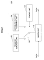
- a transmission apparatus of a first embodiment of the present invention is described with reference to Fig.2 .
- the transmission apparatus 100 of the present embodiment switches between Localized type transmission and Distributed type transmission in a time division manner. For example, the transmission apparatus 100 switches between Localized type transmission and Distributed type transmission every subframe.
- the transmission apparatus 100 includes a frequency scheduling unit 102, a distributed pattern assignment unit 104, a mapping unit 110, a switch 106 that is connected to the mapping unit 110 and that switches between the frequency scheduling unit 102 and the distributed pattern assignment unit 104, and a control unit 108 for controlling the switch 106.
- the frequency scheduling unit 102 performs assignment of a frequency block for each user in a time when performing Localized type transmission. For example, the frequency scheduling unit 102 assigns a frequency block to each user based on frequency selective fading, for example.
- the frequency block is a unit obtained by dividing a system bandwidth into blocks each having continuous frequency subcarriers.
- the distributed pattern assignment unit 104 performs assignment of subcarriers for each user in a time when performing Distributed type transmission. For example, the distributed pattern assignment unit 104 assigns distributed type frequency blocks to each user as a unit by distributing them over the whole assigned band, the distributed type frequency blocks including frequency subcarriers that are discretely distributed in a system bandwidth. For example, the distributed type frequency block is formed by one or more subcarriers and a divided subframe obtained by dividing a subframe.
- positions at which distributed type frequency blocks are placed in a time when performing Distributed type transmission are predetermined as a Distributed pattern.
- the distributed pattern assignment unit 104 places the distributed type frequency blocks based on the Distributed pattern.
- the distributed pattern assignment unit 104 may select one from the plurality of Distributed patterns based on a predetermined condition to place distributed type frequency blocks based on the selected Distributed pattern.
- the switch 106 switches between Localized type transmission and Distributed type transmission.
- the control unit 108 performs control for the switch 106.
- the control unit 108 controls the switch in units of predetermined periods that is subframes, for example.
- Localized type transmission and Distributed type transmission are switched in units of subframes.
- the control unit 108 controls the switch 106 such that Localized type transmission and Distributed type transmission are switched in a fixed proportion, that is, in the proportion of three to one, for example.
- control unit 108 may control the switch 106 so as to switch between the Localized type transmission and the Distributed type transmission in a proportion of traffic.
- the mapping unit 110 assigns data to a frequency block in a time domain, that is, in a subframe, for example, for performing Localized type transmission. In addition, the mapping unit 110 assigns data based on an input Distributed pattern in a time domain, that is, in a subframe, for example, for performing Distributed type transmission.
- Localized type transmission and Distributed type transmission are performed in units of time, that is, in units of subframes, for example.
- frequency diversity effect can be obtained at a maximum for both of the Localized type transmission and the Distributed type transmission.
- the transmission apparatus 100 of the present embodiment switches between the Localized type transmission and the Distributed type transmission in units of frequency blocks. For example, the transmission apparatus 100 assigns users that perform Localized type transmission and Distributed type transmission in units of frequency blocks and distributed type frequency blocks.
- the transmission apparatus 100 includes a frequency scheduling unit 102, a distributed pattern assignment unit 104 and a mapping unit 110 connected to the frequency scheduling unit 102.
- the distributed pattern assignment unit 104 is connected to the mapping unit 110.
- the frequency scheduling unit 102 performs assignment of frequency blocks for each user. For example, the frequency scheduling unit 102 assigns a frequency block to each user based on frequency selective fading. In addition, the frequency scheduling unit 102 supplies information indicating an assigned frequency block to the distributed pattern assignment unit 104 and the mapping unit 110.
- the distributed pattern assignment unit 104 places distributed type frequency blocks by distributing them over the whole of frequency blocks other than the frequency blocks assigned to users in the frequency scheduling unit 102 based on information indicating frequency blocks supplied from the frequency scheduling unit 102.
- positions for placing the distributed type frequency blocks on frequency blocks are predetermined as a Distributed pattern.
- the distributed pattern assignment unit 104 places distributed frequency blocks on frequency blocks other than the assigned frequency blocks in the frequency scheduling unit 102 so as to assign each user to the distributed type frequency blocks.
- a plurality of Distributed patterns may be prepared so that the distributed pattern assignment unit 104 may select one pattern from the plurality of Distributed patterns based on a predetermined condition, place distributed type frequency blocks based on the selected Distributed pattern to assign each user.
- the mapping unit 110 assigns data to a frequency block to which a user for performing Localized type transmission is assigned. In addition, the mapping unit 110 assigns data to distributed type frequency blocks placed on frequency blocks other than the frequency blocks to which users performing Localized type transmission are assigned.
- the transmission apparatus 100 of the present embodiment performs Localized type transmission and Distributed type transmission such that Localized type transmission and Distributed type transmission coexist in a same time, that is, in a same subframe, for example.
- the transmission apparatus 100 includes a frequency scheduling unit 102, a distributed pattern assignment unit 104, and a mapping unit 110 connected the frequency scheduling unit 102 and the distributed pattern assignment unit 104.
- the frequency scheduling unit 102 performs frequency block assignment to each user. For example, the frequency scheduling unit 102 assigns a frequency block to each user based on frequency selective fading, for example.
- the distributed pattern assignment unit 104 performs assignment of distributed type frequency blocks to each user. For example, the distributed pattern assignment unit 104 assigns distributed type frequency blocks as a unit to each user by distributing them over the whole assigned band.
- the distributed pattern assignment unit 104 makes holes in a frequency block by which Localized type transmission is performed. That is, the distributed pattern assignment unit 104 reserves resources for performing Distributed type transmission beforehand or performs puncturing so as to embed data for performing Distributed type transmission.
- positions at which distributed type frequency blocks are placed are predetermined as a Distributed pattern.
- the distributed pattern assignment unit 104 places the distributed type frequency blocks based on the Distributed pattern to assign each user.
- the distributed pattern assignment unit 104 may select one from the plurality of Distributed patterns based on a predetermined condition to place distributed type frequency blocks based on the selected Distributed pattern for assigning them to each user.
- the mapping unit 110 assigns data to a frequency block and a distributed type frequency block. In this case, data for Localized type transmission is assigned based on information indicating the frequency block. In addition, the mapping unit 110 assigns data based on the supplied Distributed pattern. Therefore, even in a frequency block in which data for Localized type transmission is assigned, data for Localized type transmission is not assigned in a part of distributed type frequency blocks to which data for Distributed type transmission is assigned.
- frequency diversity effect can be obtained for both of data for Localized type transmission and data for Distributed type transmission.
- the transmission apparatus 100 of the present embodiment performs Distributed type transmission in the category of Localized type transmission.
- the transmission apparatus 100 includes a frequency scheduling unit 102 and a mapping unit 110 that is connected to the frequency scheduling unit 102, receives transmission data, and that outputs transmission data.
- the frequency scheduling unit 102 performs assignment of frequency blocks to users performing Localized type transmission. For example, the frequency scheduling unit 102 assigns a frequency block to a user performing the Localized type transmission based on frequency selective fading, and supplies information indicating the assigned frequency block to the mapping unit 110.
- the frequency scheduling unit 102 performs assignment of frequency blocks also to users that perform Distributed type transmission. For example, the frequency scheduling unit 102 assigns a frequency block to a user that performs Distributed type transmission, and supplies information indicating an assigned frequency block to the mapping unit 110. The frequency scheduling unit 102 selects a frequency block to be assigned to each user using distributed type frequency blocks as a unit, for example.
- the distributed pattern assignment unit 104 assigns the distributed type frequency blocks to each user based on the Distributed pattern.
- the frequency scheduling unit 102 may select one from the plurality of Distributed patterns based on a predetermined condition, and assign distributed type frequency blocks to each user based on the selected Distributed pattern.
- the mapping unit 110 assigns data to a frequency block by which Localized type transmission is performed. In addition, the mapping unit 110 assigns data to distributed type frequency blocks that are placed on a frequency block by which Distributed type transmission is performed.
- the transmission apparatus and the transmission method of the present invention can be applied to a radio communication system.
Landscapes
- Engineering & Computer Science (AREA)
- Signal Processing (AREA)
- Computer Networks & Wireless Communication (AREA)
- Mobile Radio Communication Systems (AREA)
- Radio Transmission System (AREA)
- Transmitters (AREA)
Abstract
Description
- The present invention relates to a transmission apparatus and a transmission method.
- There are Localized type transmission and Distributed type transmission as a transmission method in a downlink data channel.
- As shown in
Fig.1A , in the Localized type transmission, each user is assigned a frequency block as a unit. For example, in the Localized type transmission, a frequency block in which frequency selectivity fading is good is assigned. Generally, the Localized type transmission is a transmission method that is effective when a transmission data size is large and frequency scheduling effect is aimed. - As shown in
Fig.1B , in the Distributed type transmission, data is transmitted by distributing the data over the whole of an assigned band irrespective of frequency blocks. For example, the Distributed type transmission is used in a state in which frequency scheduling cannot be performed due to high-speed movement, and is used when transmission data is small such as VoIP. Generally, the Distributed type transmission is a transmission method effective when transmission data size is small and frequency diversity effect is aimed. - However, the above-mentioned background art has following problems.
- It is necessary that one system supports communications for cases from low speed movement to high speed movement.
- In addition, it is necessary that one system supports various packets from packets of large data size such as Web browsing to packets of small data size such as VoIP.
- Thus, the present invention is contrived for solving the above-mentioned problem, and the object is to provide a transmission apparatus and a transmission method that can support the Localized type transmission and the Distributed type transmission using one system.
- For solving the problem, a transmission apparatus of the present invention includes, as a feature, assignment means configured to assign, to each user, one of a frequency block that is obtained by dividing a system bandwidth into each block of continuous frequency subcarriers and a distributed type frequency block that include a frequency subcarrier that is discretely distributed in the system bandwidth; and mapping means configured to assign transmission data to one of the frequency block and the distributed type frequency block according to the assignment.
- By configuring like this, Localized type transmission and Distributed type transmission can be supported by one system.
- A transmission method of the present invention includes, as a feature, an assignment step of assigning, to each user, one of a frequency block that is obtained by dividing a system bandwidth into each block of continuous frequency subcarriers and a distributed type frequency block that includes a frequency subcarrier that is discretely distributed in the system bandwidth; and a mapping step of assigning transmission data to one of the frequency block and the distributed type frequency block according to the assignment.
- By configuring like this, Localized type transmission and Distributed type transmission can be supported by one system.
- According to embodiments of the present invention, a transmission apparatus and a transmission method that can support the Localized type transmission and the Distributed type transmission using one system can be realized.
-
-
Fig.1A is a schematic diagram indicating Localized type transmission; -
Fig.1B is a schematic diagram indicating Distributed type transmission; -
Fig.2 is a partial block diagram showing a transmission apparatus according to an embodiment of the present invention; -
Fig.3 is a schematic diagram showing operation of the transmission apparatus according to an embodiment of the present invention; -
Fig.4 is a partial block diagram showing a transmission apparatus according to an embodiment of the present invention; -
Fig.5 is a schematic diagram showing operation of the transmission apparatus according to an embodiment of the present invention; -
Fig.6 is a partial block diagram showing a transmission apparatus according to an embodiment of the present invention; -
Fig.7 is a schematic diagram showing operation of the transmission apparatus according to an embodiment of the present invention; -
Fig.8 is a partial block diagram showing a transmission apparatus according to an embodiment of the present invention; and -
Fig.9 is a schematic diagram showing operation of the transmission apparatus according to an embodiment of the present invention. - Next, preferred embodiments for carrying out the present invention are described with reference to figures based on the following embodiments.
- By the way, in all of the figures for explaining the embodiments, parts having the same function are represented by a same symbol and repeating descriptions are not provided.
- A transmission apparatus of a first embodiment of the present invention is described with reference to
Fig.2 . - The
transmission apparatus 100 of the present embodiment switches between Localized type transmission and Distributed type transmission in a time division manner. For example, thetransmission apparatus 100 switches between Localized type transmission and Distributed type transmission every subframe. - The
transmission apparatus 100 includes afrequency scheduling unit 102, a distributedpattern assignment unit 104, amapping unit 110, aswitch 106 that is connected to themapping unit 110 and that switches between thefrequency scheduling unit 102 and the distributedpattern assignment unit 104, and acontrol unit 108 for controlling theswitch 106. - The
frequency scheduling unit 102 performs assignment of a frequency block for each user in a time when performing Localized type transmission. For example, thefrequency scheduling unit 102 assigns a frequency block to each user based on frequency selective fading, for example. The frequency block is a unit obtained by dividing a system bandwidth into blocks each having continuous frequency subcarriers. - The distributed
pattern assignment unit 104 performs assignment of subcarriers for each user in a time when performing Distributed type transmission. For example, the distributedpattern assignment unit 104 assigns distributed type frequency blocks to each user as a unit by distributing them over the whole assigned band, the distributed type frequency blocks including frequency subcarriers that are discretely distributed in a system bandwidth. For example, the distributed type frequency block is formed by one or more subcarriers and a divided subframe obtained by dividing a subframe. - For example, using the distributed type frequency blocks as an assignment unit, positions at which distributed type frequency blocks are placed in a time when performing Distributed type transmission are predetermined as a Distributed pattern. The distributed
pattern assignment unit 104 places the distributed type frequency blocks based on the Distributed pattern. - In addition, by preparing a plurality of Distributed patterns, the distributed
pattern assignment unit 104 may select one from the plurality of Distributed patterns based on a predetermined condition to place distributed type frequency blocks based on the selected Distributed pattern. - The
switch 106 switches between Localized type transmission and Distributed type transmission. - The
control unit 108 performs control for theswitch 106. For example, thecontrol unit 108 controls the switch in units of predetermined periods that is subframes, for example. As a result, Localized type transmission and Distributed type transmission are switched in units of subframes. For example, thecontrol unit 108 controls theswitch 106 such that Localized type transmission and Distributed type transmission are switched in a fixed proportion, that is, in the proportion of three to one, for example. - In addition, the
control unit 108 may control theswitch 106 so as to switch between the Localized type transmission and the Distributed type transmission in a proportion of traffic. - The
mapping unit 110 assigns data to a frequency block in a time domain, that is, in a subframe, for example, for performing Localized type transmission. In addition, themapping unit 110 assigns data based on an input Distributed pattern in a time domain, that is, in a subframe, for example, for performing Distributed type transmission. - As a result, as shown in
Fig.3 , Localized type transmission and Distributed type transmission are performed in units of time, that is, in units of subframes, for example. - Accordingly, frequency diversity effect can be obtained at a maximum for both of the Localized type transmission and the Distributed type transmission.
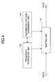
- Next, a transmission apparatus of the second embodiment of the present invention is described with reference to
Fig.4 . - The
transmission apparatus 100 of the present embodiment switches between the Localized type transmission and the Distributed type transmission in units of frequency blocks. For example, thetransmission apparatus 100 assigns users that perform Localized type transmission and Distributed type transmission in units of frequency blocks and distributed type frequency blocks. - The
transmission apparatus 100 includes afrequency scheduling unit 102, a distributedpattern assignment unit 104 and amapping unit 110 connected to thefrequency scheduling unit 102. The distributedpattern assignment unit 104 is connected to themapping unit 110. - The
frequency scheduling unit 102 performs assignment of frequency blocks for each user. For example, thefrequency scheduling unit 102 assigns a frequency block to each user based on frequency selective fading. In addition, thefrequency scheduling unit 102 supplies information indicating an assigned frequency block to the distributedpattern assignment unit 104 and themapping unit 110. - The distributed
pattern assignment unit 104 places distributed type frequency blocks by distributing them over the whole of frequency blocks other than the frequency blocks assigned to users in thefrequency scheduling unit 102 based on information indicating frequency blocks supplied from thefrequency scheduling unit 102. - For example, using distributed type frequency blocks as an assignment unit, positions for placing the distributed type frequency blocks on frequency blocks are predetermined as a Distributed pattern. The distributed
pattern assignment unit 104 places distributed frequency blocks on frequency blocks other than the assigned frequency blocks in thefrequency scheduling unit 102 so as to assign each user to the distributed type frequency blocks. - In addition, a plurality of Distributed patterns may be prepared so that the distributed
pattern assignment unit 104 may select one pattern from the plurality of Distributed patterns based on a predetermined condition, place distributed type frequency blocks based on the selected Distributed pattern to assign each user. - The
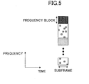
mapping unit 110 assigns data to a frequency block to which a user for performing Localized type transmission is assigned. In addition, themapping unit 110 assigns data to distributed type frequency blocks placed on frequency blocks other than the frequency blocks to which users performing Localized type transmission are assigned. - As a result, as shown in
Fig.5 , data for Localized type transmission and data for Distributed type transmission are divided in units of frequency blocks and transmitted. - Accordingly, bad influences to scheduling effects in the Localized type transmission can be decreased compared with the case in which Localized type transmission and Distributed type transmission are switched in a time division manner.
- In addition, since the whole subframe is used, flexibility in the time direction can be improved. For example, in the case when the Localized type transmission and the Distributed type transmission are switched in the time division manner, retransmission for the Localized type transmission can be performed only during a time when Localized type transmission is performed, and retransmission for Distributed type transmission can be performed only during a time when Distributed type transmission is performed. According to the
transmission apparatus 100 of the present embodiment, such temporal restriction in the retransmission control can be decreased. - Next, a transmission apparatus of the third embodiment of the present invention is described with reference to
Fig.6 . - The
transmission apparatus 100 of the present embodiment performs Localized type transmission and Distributed type transmission such that Localized type transmission and Distributed type transmission coexist in a same time, that is, in a same subframe, for example. - The
transmission apparatus 100 includes afrequency scheduling unit 102, a distributedpattern assignment unit 104, and amapping unit 110 connected thefrequency scheduling unit 102 and the distributedpattern assignment unit 104. - The
frequency scheduling unit 102 performs frequency block assignment to each user. For example, thefrequency scheduling unit 102 assigns a frequency block to each user based on frequency selective fading, for example. - The distributed
pattern assignment unit 104 performs assignment of distributed type frequency blocks to each user. For example, the distributedpattern assignment unit 104 assigns distributed type frequency blocks as a unit to each user by distributing them over the whole assigned band. - For example, the distributed
pattern assignment unit 104 makes holes in a frequency block by which Localized type transmission is performed. That is, the distributedpattern assignment unit 104 reserves resources for performing Distributed type transmission beforehand or performs puncturing so as to embed data for performing Distributed type transmission. - In this case, using distributed type frequency blocks as assignment units, positions at which distributed type frequency blocks are placed are predetermined as a Distributed pattern. The distributed
pattern assignment unit 104 places the distributed type frequency blocks based on the Distributed pattern to assign each user. - In addition, by preparing a plurality of Distributed patterns, the distributed
pattern assignment unit 104 may select one from the plurality of Distributed patterns based on a predetermined condition to place distributed type frequency blocks based on the selected Distributed pattern for assigning them to each user. - The
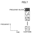
mapping unit 110 assigns data to a frequency block and a distributed type frequency block. In this case, data for Localized type transmission is assigned based on information indicating the frequency block. In addition, themapping unit 110 assigns data based on the supplied Distributed pattern. Therefore, even in a frequency block in which data for Localized type transmission is assigned, data for Localized type transmission is not assigned in a part of distributed type frequency blocks to which data for Distributed type transmission is assigned. - As a result, as shown in
Fig.7 , data for Localized type transmission and data for Distributed type transmission are transmitted such that they are coexist in a same time. - Accordingly, frequency diversity effect can be obtained for both of data for Localized type transmission and data for Distributed type transmission.
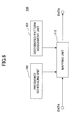
- Next, a transmission apparatus according to a fourth embodiment of the present invention is described with reference to
Fig.8 . - The
transmission apparatus 100 of the present embodiment performs Distributed type transmission in the category of Localized type transmission. - The
transmission apparatus 100 includes afrequency scheduling unit 102 and amapping unit 110 that is connected to thefrequency scheduling unit 102, receives transmission data, and that outputs transmission data. - The
frequency scheduling unit 102 performs assignment of frequency blocks to users performing Localized type transmission. For example, thefrequency scheduling unit 102 assigns a frequency block to a user performing the Localized type transmission based on frequency selective fading, and supplies information indicating the assigned frequency block to themapping unit 110. - In addition, the
frequency scheduling unit 102 performs assignment of frequency blocks also to users that perform Distributed type transmission. For example, thefrequency scheduling unit 102 assigns a frequency block to a user that performs Distributed type transmission, and supplies information indicating an assigned frequency block to themapping unit 110. Thefrequency scheduling unit 102 selects a frequency block to be assigned to each user using distributed type frequency blocks as a unit, for example. - In addition, considering the distribution type frequency blocks as an assignment unit, positions where distributed type frequency blocks are placed in a frequency block are predetermined as a Distributed pattern. The distributed
pattern assignment unit 104 assigns the distributed type frequency blocks to each user based on the Distributed pattern. - In addition, by preparing a plurality of Distributed patterns, the
frequency scheduling unit 102 may select one from the plurality of Distributed patterns based on a predetermined condition, and assign distributed type frequency blocks to each user based on the selected Distributed pattern. - The
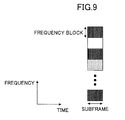
mapping unit 110 assigns data to a frequency block by which Localized type transmission is performed. In addition, themapping unit 110 assigns data to distributed type frequency blocks that are placed on a frequency block by which Distributed type transmission is performed. - As a result, as shown in
Fig.9 , data for Localized type transmission and data for Distributed type transmission are transmitted using frequency blocks as assignment units. - Accordingly, signaling information that is necessary for performing Distributed type transmission can be made unnecessary.
- The present international application claims priority based on Japanese patent application No.
2006-009298 2006-009298 - The transmission apparatus and the transmission method of the present invention can be applied to a radio communication system.
Claims (8)
- A transmission apparatus comprising:assignment means configured to assign, to each user, one of a frequency block that is obtained by dividing a system bandwidth into each block of continuous frequency subcarriers and a distributed type frequency block that include a frequency subcarrier that is discretely distributed in the system bandwidth; andmapping means configured to assign transmission data to one of the frequency block and the distributed type frequency block according to the assignment.
- The transmission apparatus as claimed in claim 1, comprising:control means configured to switch between assignment of the frequency block and assignment of the distributed type frequency block based on a predetermined period.
- The transmission apparatus as claimed in claim 1, wherein the assignment means assigns the distributed frequency block to each user in a band other than a frequency band to which the frequency block is assigned.
- The transmission apparatus as claimed in claim 1, wherein the assignment means assigns the distributed type frequency block to a frequency band in which the frequency block is assigned.
- A transmission method comprising:an assignment step of assigning, to each user, one of a frequency block that is obtained by dividing a system bandwidth into each block of continuous frequency subcarriers and a distributed type frequency block that includes a frequency subcarrier that is discretely distributed in the system bandwidth; anda mapping step of assigning transmission data to one of the frequency block and the distributed type frequency block according to the assignment.
- The transmission method as claimed in claim 5, comprising:a control step of switching between assignment of the frequency block and assignment of the distributed type frequency block based on a predetermined period.
- The transmission method as claimed in claim 6, wherein the assignment step assigns the distributed frequency block to each user in a band other than a frequency band to which the frequency block is assigned.
- The transmission method as claimed in claim 5, wherein the assignment means assigns the distributed type frequency block in a frequency band in which the frequency block is assigned.
Applications Claiming Priority (2)
| Application Number | Priority Date | Filing Date | Title |
|---|---|---|---|
| JP2006009298A JP4347300B2 (en) | 2006-01-17 | 2006-01-17 | Transmitting apparatus and transmitting method |
| PCT/JP2007/050142 WO2007083543A1 (en) | 2006-01-17 | 2007-01-10 | Transmitting device and transmitting method |
Publications (3)
| Publication Number | Publication Date |
|---|---|
| EP1978663A1 true EP1978663A1 (en) | 2008-10-08 |
| EP1978663A4 EP1978663A4 (en) | 2013-08-07 |
| EP1978663B1 EP1978663B1 (en) | 2017-03-15 |
Family
ID=38287496
Family Applications (1)
| Application Number | Title | Priority Date | Filing Date |
|---|---|---|---|
| EP07706489.7A Active EP1978663B1 (en) | 2006-01-17 | 2007-01-10 | Transmitting device and transmitting method with distributed type or localized type transmission |
Country Status (12)
| Country | Link |
|---|---|
| US (1) | US8477696B2 (en) |
| EP (1) | EP1978663B1 (en) |
| JP (1) | JP4347300B2 (en) |
| KR (1) | KR100989041B1 (en) |
| CN (2) | CN101895365B (en) |
| BR (1) | BRPI0706602A2 (en) |
| CA (1) | CA2637638C (en) |
| MX (1) | MX2008009128A (en) |
| PT (1) | PT1978663T (en) |
| RU (1) | RU2421915C2 (en) |
| TW (1) | TW200733666A (en) |
| WO (1) | WO2007083543A1 (en) |
Cited By (1)
| Publication number | Priority date | Publication date | Assignee | Title |
|---|---|---|---|---|
| EP2822320A4 (en) * | 2012-02-29 | 2015-11-04 | Kyocera Corp | Mobile communication system, mobile communication method and wireless base station |
Families Citing this family (4)
| Publication number | Priority date | Publication date | Assignee | Title |
|---|---|---|---|---|
| KR101645907B1 (en) | 2007-11-05 | 2016-08-04 | 애플 인크. | Methods and systems for resource allocation |
| KR100936696B1 (en) | 2007-11-16 | 2010-01-13 | 고려대학교 산학협력단 | Method and apparatus for Staggered Zone Resource AllocationSZRA in OFDMA systems |
| WO2010075901A1 (en) * | 2008-12-31 | 2010-07-08 | Telecom Italia S.P.A. | Downlink transmission scheduling in multi-carrier networks |
| JP7068068B2 (en) | 2018-06-26 | 2022-05-16 | 株式会社東芝 | Detection area database creation device |
Citations (3)
| Publication number | Priority date | Publication date | Assignee | Title |
|---|---|---|---|---|
| JP2002111631A (en) * | 2000-10-04 | 2002-04-12 | Yrp Mobile Telecommunications Key Tech Res Lab Co Ltd | System and apparatus for radio communication |
| WO2005088882A1 (en) * | 2004-03-15 | 2005-09-22 | Nortel Netowrks Limited | Pilot design for ofdm systems with four transmit antennas |
| WO2005114940A1 (en) * | 2004-05-18 | 2005-12-01 | Qualcomm Incorporated | Slot-to-interlace and interlace-to-slot converters for an ofdm system |
Family Cites Families (20)
| Publication number | Priority date | Publication date | Assignee | Title |
|---|---|---|---|---|
| US2007006A (en) * | 1931-11-27 | 1935-07-02 | Free Wheeling Patents Corp | Free wheeling mechanism |
| EP1341332A4 (en) * | 2000-12-05 | 2005-03-30 | Fujitsu Ltd | Data transmission method and apparatus |
| AU2002348618B2 (en) * | 2001-11-10 | 2004-09-23 | Samsung Electronics Co., Ltd. | STFBC coding/decoding apparatus and method in an OFDM mobile communication system |
| KR100754721B1 (en) * | 2002-04-26 | 2007-09-03 | 삼성전자주식회사 | Apparatus and method for transmitting and receiving multiplexed data in an orthogonal frequency division multiplexing communication system |
| JP4256158B2 (en) * | 2002-12-26 | 2009-04-22 | パナソニック株式会社 | Wireless communication apparatus and wireless communication method |
| JP3860556B2 (en) * | 2003-04-04 | 2006-12-20 | 松下電器産業株式会社 | Base station apparatus and communication method |
| DE10338053B4 (en) | 2003-08-19 | 2005-12-15 | Siemens Ag | Method for allocating radio resources and network equipment in a multicarrier radio communication system |
| JP3877215B2 (en) | 2003-10-10 | 2007-02-07 | 株式会社インテリジェント・コスモス研究機構 | Transmission device, communication system, and communication method |
| US7457231B2 (en) | 2004-05-04 | 2008-11-25 | Qualcomm Incorporated | Staggered pilot transmission for channel estimation and time tracking |
| US8577299B2 (en) * | 2004-06-04 | 2013-11-05 | Qualcomm Incorporated | Wireless communication system with configurable cyclic prefix length |
| US8098632B2 (en) * | 2005-01-21 | 2012-01-17 | Samsung Electronics Co., Ltd. | Apparatus and method for downlink scheduling in a SDMA-enabled OFDMA wireless network |
| JP4527067B2 (en) * | 2005-03-31 | 2010-08-18 | 株式会社エヌ・ティ・ティ・ドコモ | Mobile station, transmission method, and mobile communication system |
| JP4567628B2 (en) * | 2005-06-14 | 2010-10-20 | 株式会社エヌ・ティ・ティ・ドコモ | Mobile station, transmission method and communication system |
| US8654712B2 (en) | 2005-06-16 | 2014-02-18 | Qualcomm Incorporated | OFDMA reverse link scheduling |
| JP4836951B2 (en) | 2005-06-24 | 2011-12-14 | パナソニック株式会社 | Radio communication base station apparatus and radio communication method in multi-carrier communication |
| US8045512B2 (en) | 2005-10-27 | 2011-10-25 | Qualcomm Incorporated | Scalable frequency band operation in wireless communication systems |
| CA2635741C (en) * | 2006-01-13 | 2013-08-13 | Qualcomm Incorporated | Localized and distributed allocation multiplexing and control |
| JP4711835B2 (en) * | 2006-01-17 | 2011-06-29 | 株式会社エヌ・ティ・ティ・ドコモ | Transmitting apparatus, receiving apparatus, and random access control method |
| US8520607B2 (en) * | 2007-01-17 | 2013-08-27 | Qualcomm Incorported | Hopping structure for control channels |
| JP5069741B2 (en) * | 2007-03-01 | 2012-11-07 | 株式会社エヌ・ティ・ティ・ドコモ | Base station apparatus and communication control method |
-
2006
- 2006-01-17 JP JP2006009298A patent/JP4347300B2/en active Active
-
2007
- 2007-01-10 US US12/161,172 patent/US8477696B2/en active Active
- 2007-01-10 EP EP07706489.7A patent/EP1978663B1/en active Active
- 2007-01-10 WO PCT/JP2007/050142 patent/WO2007083543A1/en active Application Filing
- 2007-01-10 PT PT77064897T patent/PT1978663T/en unknown
- 2007-01-10 CN CN201010189643.7A patent/CN101895365B/en active Active
- 2007-01-10 RU RU2008132422A patent/RU2421915C2/en active
- 2007-01-10 BR BRPI0706602-3A patent/BRPI0706602A2/en not_active Application Discontinuation
- 2007-01-10 CA CA 2637638 patent/CA2637638C/en active Active
- 2007-01-10 MX MX2008009128A patent/MX2008009128A/en active IP Right Grant
- 2007-01-10 KR KR20087020017A patent/KR100989041B1/en active IP Right Grant
- 2007-01-10 CN CN2007800090561A patent/CN101401337B/en not_active Expired - Fee Related
- 2007-01-15 TW TW096101407A patent/TW200733666A/en unknown
Patent Citations (3)
| Publication number | Priority date | Publication date | Assignee | Title |
|---|---|---|---|---|
| JP2002111631A (en) * | 2000-10-04 | 2002-04-12 | Yrp Mobile Telecommunications Key Tech Res Lab Co Ltd | System and apparatus for radio communication |
| WO2005088882A1 (en) * | 2004-03-15 | 2005-09-22 | Nortel Netowrks Limited | Pilot design for ofdm systems with four transmit antennas |
| WO2005114940A1 (en) * | 2004-05-18 | 2005-12-01 | Qualcomm Incorporated | Slot-to-interlace and interlace-to-slot converters for an ofdm system |
Non-Patent Citations (1)
| Title |
|---|
| See also references of WO2007083543A1 * |
Cited By (2)
| Publication number | Priority date | Publication date | Assignee | Title |
|---|---|---|---|---|
| EP2822320A4 (en) * | 2012-02-29 | 2015-11-04 | Kyocera Corp | Mobile communication system, mobile communication method and wireless base station |
| US9485766B2 (en) | 2012-02-29 | 2016-11-01 | Kyocera Corporation | Mobile communication system, mobile communication method, and radio base station |
Also Published As
| Publication number | Publication date |
|---|---|
| TWI332338B (en) | 2010-10-21 |
| KR100989041B1 (en) | 2010-10-25 |
| WO2007083543A1 (en) | 2007-07-26 |
| CN101895365B (en) | 2014-09-24 |
| JP2007194750A (en) | 2007-08-02 |
| CA2637638C (en) | 2011-03-22 |
| JP4347300B2 (en) | 2009-10-21 |
| BRPI0706602A2 (en) | 2011-03-29 |
| RU2008132422A (en) | 2010-02-27 |
| MX2008009128A (en) | 2008-10-23 |
| CA2637638A1 (en) | 2007-07-26 |
| CN101895365A (en) | 2010-11-24 |
| CN101401337A (en) | 2009-04-01 |
| EP1978663B1 (en) | 2017-03-15 |
| US8477696B2 (en) | 2013-07-02 |
| US20100111204A1 (en) | 2010-05-06 |
| PT1978663T (en) | 2017-03-29 |
| EP1978663A4 (en) | 2013-08-07 |
| KR20080100192A (en) | 2008-11-14 |
| TW200733666A (en) | 2007-09-01 |
| CN101401337B (en) | 2012-10-10 |
| RU2421915C2 (en) | 2011-06-20 |
Similar Documents
| Publication | Publication Date | Title |
|---|---|---|
| US9906345B2 (en) | Reference signal allocation for flexible data lengths | |
| KR101428738B1 (en) | Transmission device | |
| CA2612316A1 (en) | Ofdma control channel interlacing | |
| WO2007119452A1 (en) | Radio communication system, radio transmission device, and resource allocation method | |
| US11943158B2 (en) | Data communication apparatuses, data communication system and methods using reference symbols | |
| CN109196941A (en) | Communication means, terminal device and the network equipment based on wireless network | |
| US8477696B2 (en) | Transmission apparatus and transmission method for a downlink channel | |
| US8391230B2 (en) | Method and apparatus for transmitting uplink control signal in wireless communication system | |
| KR20070058045A (en) | Apparatus and method for extending cell coverage of the base station in the ofdm system | |
| KR20090024431A (en) | Method for allocating radio resource | |
| JP5198367B2 (en) | Transmission device, transmission method, user device, and communication method | |
| KR100977243B1 (en) | Method for making map in broadband wireless communication system | |
| KR20090089573A (en) | Method of data transmission using effective subcarrier mapping |
Legal Events
| Date | Code | Title | Description |
|---|---|---|---|
| PUAI | Public reference made under article 153(3) epc to a published international application that has entered the european phase |
Free format text: ORIGINAL CODE: 0009012 |
|
| 17P | Request for examination filed |
Effective date: 20080717 |
|
| AK | Designated contracting states |
Kind code of ref document: A1 Designated state(s): AT BE BG CH CY CZ DE DK EE ES FI FR GB GR HU IE IS IT LI LT LU LV MC NL PL PT RO SE SI SK TR |
|
| RIN1 | Information on inventor provided before grant (corrected) |
Inventor name: KISHIYAMA, YOSHIHISA Inventor name: SAWAHASHI, MAMORU Inventor name: HIGUCHI, KENICHI |
|
| DAX | Request for extension of the european patent (deleted) | ||
| A4 | Supplementary search report drawn up and despatched |
Effective date: 20130704 |
|
| RIC1 | Information provided on ipc code assigned before grant |
Ipc: H04B 1/69 20110101ALI20130628BHEP Ipc: H04J 1/00 20060101ALI20130628BHEP Ipc: H04J 11/00 20060101AFI20130628BHEP Ipc: H04B 7/12 20060101ALI20130628BHEP |
|
| 17Q | First examination report despatched |
Effective date: 20141219 |
|
| REG | Reference to a national code |
Ref country code: DE Ref legal event code: R079 Ref document number: 602007050172 Country of ref document: DE Free format text: PREVIOUS MAIN CLASS: H04J0011000000 Ipc: H04L0005000000 |
|
| RIC1 | Information provided on ipc code assigned before grant |
Ipc: H04L 5/00 20060101AFI20160205BHEP |
|
| GRAP | Despatch of communication of intention to grant a patent |
Free format text: ORIGINAL CODE: EPIDOSNIGR1 |
|
| RIN1 | Information on inventor provided before grant (corrected) |
Inventor name: SAWAHASHI, MAMORU C/O INTELLECTUAL PROPERTY Inventor name: KISHIYAMA, YOSHIHISA C/O INTELLECTUAL PROPERTY Inventor name: HIGUCHI, KENICHI C/O INTELLECTUAL PROPERTY |
|
| INTG | Intention to grant announced |
Effective date: 20160322 |
|
| GRAJ | Information related to disapproval of communication of intention to grant by the applicant or resumption of examination proceedings by the epo deleted |
Free format text: ORIGINAL CODE: EPIDOSDIGR1 |
|
| INTC | Intention to grant announced (deleted) | ||
| GRAP | Despatch of communication of intention to grant a patent |
Free format text: ORIGINAL CODE: EPIDOSNIGR1 |
|
| INTG | Intention to grant announced |
Effective date: 20161018 |
|
| GRAS | Grant fee paid |
Free format text: ORIGINAL CODE: EPIDOSNIGR3 |
|
| GRAA | (expected) grant |
Free format text: ORIGINAL CODE: 0009210 |
|
| RAP1 | Party data changed (applicant data changed or rights of an application transferred) |
Owner name: NTT DOCOMO, INC. |
|
| RIN1 | Information on inventor provided before grant (corrected) |
Inventor name: KISHIYAMA, YOSHIHISA Inventor name: SAWAHASHI, MAMORU Inventor name: HIGUCHI, KENICHI |
|
| RIN1 | Information on inventor provided before grant (corrected) |
Inventor name: HIGUCHI, KENICHI Inventor name: KISHIYAMA, YOSHIHISA Inventor name: SAWAHASHI, MAMORU |
|
| AK | Designated contracting states |
Kind code of ref document: B1 Designated state(s): AT BE BG CH CY CZ DE DK EE ES FI FR GB GR HU IE IS IT LI LT LU LV MC NL PL PT RO SE SI SK TR |
|
| REG | Reference to a national code |
Ref country code: CH Ref legal event code: EP Ref country code: GB Ref legal event code: FG4D |
|
| REG | Reference to a national code |
Ref country code: PT Ref legal event code: SC4A Ref document number: 1978663 Country of ref document: PT Date of ref document: 20170329 Kind code of ref document: T Free format text: AVAILABILITY OF NATIONAL TRANSLATION Effective date: 20170320 |
|
| REG | Reference to a national code |
Ref country code: IE Ref legal event code: FG4D |
|
| REG | Reference to a national code |
Ref country code: AT Ref legal event code: REF Ref document number: 876551 Country of ref document: AT Kind code of ref document: T Effective date: 20170415 |
|
| REG | Reference to a national code |
Ref country code: DE Ref legal event code: R096 Ref document number: 602007050172 Country of ref document: DE |
|
| REG | Reference to a national code |
Ref country code: NL Ref legal event code: MP Effective date: 20170315 |
|
| REG | Reference to a national code |
Ref country code: LT Ref legal event code: MG4D |
|
| PG25 | Lapsed in a contracting state [announced via postgrant information from national office to epo] |
Ref country code: LT Free format text: LAPSE BECAUSE OF FAILURE TO SUBMIT A TRANSLATION OF THE DESCRIPTION OR TO PAY THE FEE WITHIN THE PRESCRIBED TIME-LIMIT Effective date: 20170315 Ref country code: FI Free format text: LAPSE BECAUSE OF FAILURE TO SUBMIT A TRANSLATION OF THE DESCRIPTION OR TO PAY THE FEE WITHIN THE PRESCRIBED TIME-LIMIT Effective date: 20170315 Ref country code: GR Free format text: LAPSE BECAUSE OF FAILURE TO SUBMIT A TRANSLATION OF THE DESCRIPTION OR TO PAY THE FEE WITHIN THE PRESCRIBED TIME-LIMIT Effective date: 20170616 |
|
| REG | Reference to a national code |
Ref country code: AT Ref legal event code: MK05 Ref document number: 876551 Country of ref document: AT Kind code of ref document: T Effective date: 20170315 |
|
| PG25 | Lapsed in a contracting state [announced via postgrant information from national office to epo] |
Ref country code: SE Free format text: LAPSE BECAUSE OF FAILURE TO SUBMIT A TRANSLATION OF THE DESCRIPTION OR TO PAY THE FEE WITHIN THE PRESCRIBED TIME-LIMIT Effective date: 20170315 Ref country code: LV Free format text: LAPSE BECAUSE OF FAILURE TO SUBMIT A TRANSLATION OF THE DESCRIPTION OR TO PAY THE FEE WITHIN THE PRESCRIBED TIME-LIMIT Effective date: 20170315 Ref country code: BG Free format text: LAPSE BECAUSE OF FAILURE TO SUBMIT A TRANSLATION OF THE DESCRIPTION OR TO PAY THE FEE WITHIN THE PRESCRIBED TIME-LIMIT Effective date: 20170615 |
|
| PG25 | Lapsed in a contracting state [announced via postgrant information from national office to epo] |
Ref country code: NL Free format text: LAPSE BECAUSE OF FAILURE TO SUBMIT A TRANSLATION OF THE DESCRIPTION OR TO PAY THE FEE WITHIN THE PRESCRIBED TIME-LIMIT Effective date: 20170315 |
|
| PG25 | Lapsed in a contracting state [announced via postgrant information from national office to epo] |
Ref country code: SK Free format text: LAPSE BECAUSE OF FAILURE TO SUBMIT A TRANSLATION OF THE DESCRIPTION OR TO PAY THE FEE WITHIN THE PRESCRIBED TIME-LIMIT Effective date: 20170315 Ref country code: ES Free format text: LAPSE BECAUSE OF FAILURE TO SUBMIT A TRANSLATION OF THE DESCRIPTION OR TO PAY THE FEE WITHIN THE PRESCRIBED TIME-LIMIT Effective date: 20170315 Ref country code: EE Free format text: LAPSE BECAUSE OF FAILURE TO SUBMIT A TRANSLATION OF THE DESCRIPTION OR TO PAY THE FEE WITHIN THE PRESCRIBED TIME-LIMIT Effective date: 20170315 Ref country code: CZ Free format text: LAPSE BECAUSE OF FAILURE TO SUBMIT A TRANSLATION OF THE DESCRIPTION OR TO PAY THE FEE WITHIN THE PRESCRIBED TIME-LIMIT Effective date: 20170315 Ref country code: RO Free format text: LAPSE BECAUSE OF FAILURE TO SUBMIT A TRANSLATION OF THE DESCRIPTION OR TO PAY THE FEE WITHIN THE PRESCRIBED TIME-LIMIT Effective date: 20170315 Ref country code: AT Free format text: LAPSE BECAUSE OF FAILURE TO SUBMIT A TRANSLATION OF THE DESCRIPTION OR TO PAY THE FEE WITHIN THE PRESCRIBED TIME-LIMIT Effective date: 20170315 |
|
| PG25 | Lapsed in a contracting state [announced via postgrant information from national office to epo] |
Ref country code: PL Free format text: LAPSE BECAUSE OF FAILURE TO SUBMIT A TRANSLATION OF THE DESCRIPTION OR TO PAY THE FEE WITHIN THE PRESCRIBED TIME-LIMIT Effective date: 20170315 Ref country code: IS Free format text: LAPSE BECAUSE OF FAILURE TO SUBMIT A TRANSLATION OF THE DESCRIPTION OR TO PAY THE FEE WITHIN THE PRESCRIBED TIME-LIMIT Effective date: 20170715 |
|
| REG | Reference to a national code |
Ref country code: DE Ref legal event code: R097 Ref document number: 602007050172 Country of ref document: DE |
|
| PLBE | No opposition filed within time limit |
Free format text: ORIGINAL CODE: 0009261 |
|
| STAA | Information on the status of an ep patent application or granted ep patent |
Free format text: STATUS: NO OPPOSITION FILED WITHIN TIME LIMIT |
|
| REG | Reference to a national code |
Ref country code: FR Ref legal event code: PLFP Year of fee payment: 12 |
|
| PG25 | Lapsed in a contracting state [announced via postgrant information from national office to epo] |
Ref country code: DK Free format text: LAPSE BECAUSE OF FAILURE TO SUBMIT A TRANSLATION OF THE DESCRIPTION OR TO PAY THE FEE WITHIN THE PRESCRIBED TIME-LIMIT Effective date: 20170315 |
|
| 26N | No opposition filed |
Effective date: 20171218 |
|
| PG25 | Lapsed in a contracting state [announced via postgrant information from national office to epo] |
Ref country code: SI Free format text: LAPSE BECAUSE OF FAILURE TO SUBMIT A TRANSLATION OF THE DESCRIPTION OR TO PAY THE FEE WITHIN THE PRESCRIBED TIME-LIMIT Effective date: 20170315 Ref country code: IT Free format text: LAPSE BECAUSE OF FAILURE TO SUBMIT A TRANSLATION OF THE DESCRIPTION OR TO PAY THE FEE WITHIN THE PRESCRIBED TIME-LIMIT Effective date: 20170315 |
|
| REG | Reference to a national code |
Ref country code: CH Ref legal event code: PL |
|
| PG25 | Lapsed in a contracting state [announced via postgrant information from national office to epo] |
Ref country code: LU Free format text: LAPSE BECAUSE OF NON-PAYMENT OF DUE FEES Effective date: 20180110 |
|
| REG | Reference to a national code |
Ref country code: IE Ref legal event code: MM4A |
|
| REG | Reference to a national code |
Ref country code: BE Ref legal event code: MM Effective date: 20180131 |
|
| PG25 | Lapsed in a contracting state [announced via postgrant information from national office to epo] |
Ref country code: CH Free format text: LAPSE BECAUSE OF NON-PAYMENT OF DUE FEES Effective date: 20180131 Ref country code: LI Free format text: LAPSE BECAUSE OF NON-PAYMENT OF DUE FEES Effective date: 20180131 Ref country code: BE Free format text: LAPSE BECAUSE OF NON-PAYMENT OF DUE FEES Effective date: 20180131 |
|
| PG25 | Lapsed in a contracting state [announced via postgrant information from national office to epo] |
Ref country code: IE Free format text: LAPSE BECAUSE OF NON-PAYMENT OF DUE FEES Effective date: 20180110 |
|
| PG25 | Lapsed in a contracting state [announced via postgrant information from national office to epo] |
Ref country code: MC Free format text: LAPSE BECAUSE OF FAILURE TO SUBMIT A TRANSLATION OF THE DESCRIPTION OR TO PAY THE FEE WITHIN THE PRESCRIBED TIME-LIMIT Effective date: 20170315 |
|
| PG25 | Lapsed in a contracting state [announced via postgrant information from national office to epo] |
Ref country code: TR Free format text: LAPSE BECAUSE OF FAILURE TO SUBMIT A TRANSLATION OF THE DESCRIPTION OR TO PAY THE FEE WITHIN THE PRESCRIBED TIME-LIMIT Effective date: 20170315 |
|
| PG25 | Lapsed in a contracting state [announced via postgrant information from national office to epo] |
Ref country code: HU Free format text: LAPSE BECAUSE OF FAILURE TO SUBMIT A TRANSLATION OF THE DESCRIPTION OR TO PAY THE FEE WITHIN THE PRESCRIBED TIME-LIMIT; INVALID AB INITIO Effective date: 20070110 |
|
| PG25 | Lapsed in a contracting state [announced via postgrant information from national office to epo] |
Ref country code: CY Free format text: LAPSE BECAUSE OF FAILURE TO SUBMIT A TRANSLATION OF THE DESCRIPTION OR TO PAY THE FEE WITHIN THE PRESCRIBED TIME-LIMIT Effective date: 20170315 |
|
| PGFP | Annual fee paid to national office [announced via postgrant information from national office to epo] |
Ref country code: FR Payment date: 20230124 Year of fee payment: 17 |
|
| P01 | Opt-out of the competence of the unified patent court (upc) registered |
Effective date: 20230517 |
|
| PGFP | Annual fee paid to national office [announced via postgrant information from national office to epo] |
Ref country code: PT Payment date: 20231221 Year of fee payment: 18 |
|
| PGFP | Annual fee paid to national office [announced via postgrant information from national office to epo] |
Ref country code: DE Payment date: 20240119 Year of fee payment: 18 Ref country code: GB Payment date: 20240119 Year of fee payment: 18 |