EP1978658A2 - Dispositifs et méthodes d'incorporation et de décodage de codes dans des signaux audio - Google Patents
Dispositifs et méthodes d'incorporation et de décodage de codes dans des signaux audio Download PDFInfo
- Publication number
- EP1978658A2 EP1978658A2 EP08009783A EP08009783A EP1978658A2 EP 1978658 A2 EP1978658 A2 EP 1978658A2 EP 08009783 A EP08009783 A EP 08009783A EP 08009783 A EP08009783 A EP 08009783A EP 1978658 A2 EP1978658 A2 EP 1978658A2
- Authority
- EP
- European Patent Office
- Prior art keywords
- code
- frequency
- audio signal
- component
- masking
- Prior art date
- Legal status (The legal status is an assumption and is not a legal conclusion. Google has not performed a legal analysis and makes no representation as to the accuracy of the status listed.)
- Withdrawn
Links
Images


Classifications
-
- H—ELECTRICITY
- H04—ELECTRIC COMMUNICATION TECHNIQUE
- H04H—BROADCAST COMMUNICATION
- H04H20/00—Arrangements for broadcast or for distribution combined with broadcast
- H04H20/28—Arrangements for simultaneous broadcast of plural pieces of information
- H04H20/30—Arrangements for simultaneous broadcast of plural pieces of information by a single channel
- H04H20/31—Arrangements for simultaneous broadcast of plural pieces of information by a single channel using in-band signals, e.g. subsonic or cue signal
-
- H—ELECTRICITY
- H04—ELECTRIC COMMUNICATION TECHNIQUE
- H04H—BROADCAST COMMUNICATION
- H04H60/00—Arrangements for broadcast applications with a direct linking to broadcast information or broadcast space-time; Broadcast-related systems
- H04H60/35—Arrangements for identifying or recognising characteristics with a direct linkage to broadcast information or to broadcast space-time, e.g. for identifying broadcast stations or for identifying users
- H04H60/37—Arrangements for identifying or recognising characteristics with a direct linkage to broadcast information or to broadcast space-time, e.g. for identifying broadcast stations or for identifying users for identifying segments of broadcast information, e.g. scenes or extracting programme ID
-
- H—ELECTRICITY
- H04—ELECTRIC COMMUNICATION TECHNIQUE
- H04H—BROADCAST COMMUNICATION
- H04H60/00—Arrangements for broadcast applications with a direct linking to broadcast information or broadcast space-time; Broadcast-related systems
- H04H60/35—Arrangements for identifying or recognising characteristics with a direct linkage to broadcast information or to broadcast space-time, e.g. for identifying broadcast stations or for identifying users
- H04H60/38—Arrangements for identifying or recognising characteristics with a direct linkage to broadcast information or to broadcast space-time, e.g. for identifying broadcast stations or for identifying users for identifying broadcast time or space
- H04H60/40—Arrangements for identifying or recognising characteristics with a direct linkage to broadcast information or to broadcast space-time, e.g. for identifying broadcast stations or for identifying users for identifying broadcast time or space for identifying broadcast time
-
- H—ELECTRICITY
- H04—ELECTRIC COMMUNICATION TECHNIQUE
- H04H—BROADCAST COMMUNICATION
- H04H60/00—Arrangements for broadcast applications with a direct linking to broadcast information or broadcast space-time; Broadcast-related systems
- H04H60/35—Arrangements for identifying or recognising characteristics with a direct linkage to broadcast information or to broadcast space-time, e.g. for identifying broadcast stations or for identifying users
- H04H60/38—Arrangements for identifying or recognising characteristics with a direct linkage to broadcast information or to broadcast space-time, e.g. for identifying broadcast stations or for identifying users for identifying broadcast time or space
- H04H60/41—Arrangements for identifying or recognising characteristics with a direct linkage to broadcast information or to broadcast space-time, e.g. for identifying broadcast stations or for identifying users for identifying broadcast time or space for identifying broadcast space, i.e. broadcast channels, broadcast stations or broadcast areas
- H04H60/44—Arrangements for identifying or recognising characteristics with a direct linkage to broadcast information or to broadcast space-time, e.g. for identifying broadcast stations or for identifying users for identifying broadcast time or space for identifying broadcast space, i.e. broadcast channels, broadcast stations or broadcast areas for identifying broadcast stations
-
- H—ELECTRICITY
- H04—ELECTRIC COMMUNICATION TECHNIQUE
- H04H—BROADCAST COMMUNICATION
- H04H60/00—Arrangements for broadcast applications with a direct linking to broadcast information or broadcast space-time; Broadcast-related systems
- H04H60/35—Arrangements for identifying or recognising characteristics with a direct linkage to broadcast information or to broadcast space-time, e.g. for identifying broadcast stations or for identifying users
- H04H60/45—Arrangements for identifying or recognising characteristics with a direct linkage to broadcast information or to broadcast space-time, e.g. for identifying broadcast stations or for identifying users for identifying users
-
- H—ELECTRICITY
- H04—ELECTRIC COMMUNICATION TECHNIQUE
- H04H—BROADCAST COMMUNICATION
- H04H60/00—Arrangements for broadcast applications with a direct linking to broadcast information or broadcast space-time; Broadcast-related systems
- H04H60/56—Arrangements characterised by components specially adapted for monitoring, identification or recognition covered by groups H04H60/29-H04H60/54
- H04H60/58—Arrangements characterised by components specially adapted for monitoring, identification or recognition covered by groups H04H60/29-H04H60/54 of audio
-
- H—ELECTRICITY
- H04—ELECTRIC COMMUNICATION TECHNIQUE
- H04H—BROADCAST COMMUNICATION
- H04H20/00—Arrangements for broadcast or for distribution combined with broadcast
- H04H20/12—Arrangements for observation, testing or troubleshooting
- H04H20/14—Arrangements for observation, testing or troubleshooting for monitoring programmes
-
- H—ELECTRICITY
- H04—ELECTRIC COMMUNICATION TECHNIQUE
- H04H—BROADCAST COMMUNICATION
- H04H60/00—Arrangements for broadcast applications with a direct linking to broadcast information or broadcast space-time; Broadcast-related systems
- H04H60/09—Arrangements for device control with a direct linkage to broadcast information or to broadcast space-time; Arrangements for control of broadcast-related services
- H04H60/13—Arrangements for device control affected by the broadcast information
-
- H—ELECTRICITY
- H04—ELECTRIC COMMUNICATION TECHNIQUE
- H04H—BROADCAST COMMUNICATION
- H04H60/00—Arrangements for broadcast applications with a direct linking to broadcast information or broadcast space-time; Broadcast-related systems
- H04H60/09—Arrangements for device control with a direct linkage to broadcast information or to broadcast space-time; Arrangements for control of broadcast-related services
- H04H60/14—Arrangements for conditional access to broadcast information or to broadcast-related services
- H04H60/17—Arrangements for conditional access to broadcast information or to broadcast-related services on recording information
-
- H—ELECTRICITY
- H04—ELECTRIC COMMUNICATION TECHNIQUE
- H04H—BROADCAST COMMUNICATION
- H04H60/00—Arrangements for broadcast applications with a direct linking to broadcast information or broadcast space-time; Broadcast-related systems
- H04H60/61—Arrangements for services using the result of monitoring, identification or recognition covered by groups H04H60/29-H04H60/54
- H04H60/63—Arrangements for services using the result of monitoring, identification or recognition covered by groups H04H60/29-H04H60/54 for services of sales
-
- H—ELECTRICITY
- H04—ELECTRIC COMMUNICATION TECHNIQUE
- H04H—BROADCAST COMMUNICATION
- H04H60/00—Arrangements for broadcast applications with a direct linking to broadcast information or broadcast space-time; Broadcast-related systems
- H04H60/61—Arrangements for services using the result of monitoring, identification or recognition covered by groups H04H60/29-H04H60/54
- H04H60/66—Arrangements for services using the result of monitoring, identification or recognition covered by groups H04H60/29-H04H60/54 for using the result on distributors' side
Definitions
- the present invention relates to apparatus and methods for including codes in audio signals and decoding such codes.
- a further technique has been suggested in which dual tone multifrequency (DTMF) codes are inserted in an audio signal.
- the DTMF codes are purportedly detected based on their frequencies and durations.
- audio signal components can be mistaken for one or both tones of each DTMF code, so that either the presence of a code can be missed by the detector or signal components can be mistaken for a DTMF code.
- each DTMF code includes a tone common to another DTMF code. Accordingly, a signal component corresponding to a tone of a different DTMF code can combine with the tone of a DTMF code which is simultaneously present in the signal to result in a false detection.
- a further object of the present invention is to provide decoding apparatus and methods for reliably recovering codes present in audio signals.
- apparatus and methods for including a code having at least one code frequency component with an audio signal having a plurality of audio signal frequency components comprise the means for and the steps of:
- an apparatus for including a code having at least one code frequency component with an audio signal having a plurality of audio signal frequency components comprises: a digital computer having an input for receiving the audio signal, the digital computer being programmed to evaluate respective abilities of first and second sets of the plurality of audio signal frequency components to mask the at least one code frequency component to human hearing to produce respective first and second masking evaluations, the second set of the plurality of audio signal frequency components differing from the first set thereof, the digital computer being further programmed to assign an amplitude to the at least one code frequency component based on a selected one of the first and second masking evaluations; and means for including the at least one code frequency component with the audio signal.
- apparatus and methods for including a code having a plurality of code frequency components with an audio signal having a plurality of audio signal frequency components comprise the means for and the steps of, respectively: evaluating an ability of at least one of the plurality of audio signal frequency components to mask a code frequency component having the first frequency to human hearing to produce a first respective masking evaluation; evaluating an ability of at least one of the plurality of audio signal frequency components to mask a code frequency component having the second frequency to human hearing to produce a second respective masking evaluation; assigning a respective amplitude to the first code frequency component based on the first respective masking evaluation and assigning a respective amplitude to the second code frequency component based on the second respective masking evaluation; and including the plurality of code frequency components with the audio signal.
- an apparatus for including a code having a plurality of code frequency components with an audio signal having a plurality of audio signal frequency components, the plurality of code frequency components including a first code frequency component having a first frequency and a second code frequency component having a second code frequency different from the first frequency comprises: a digital computer having an input for receiving the audio signal, the digital computer being programmed to evaluate an ability of at least one of the plurality of audio signal frequency components to mask a code frequency component having the first frequency to human hearing to produce a first respective masking evaluation and to evaluate an ability of at least one of the plurality of audio signal frequency components to mask a code frequency component having the second frequency to human hearing to produce a second respective masking evaluation; the digital computer being further programmed to assign a corresponding amplitude to the first code frequency component based on the first respective masking evaluation and to assign a corresponding amplitude to the second code frequency component based on the second respective masking evaluation; and means for including the plurality of code frequency components with the audio
- apparatus and methods for including a code having at least one code frequency component with an audio signal including a plurality of audio signal frequency components comprise the means for and the steps of, respectively: evaluating an ability of at least one of the plurality of audio signal frequency components within a first audio signal interval on a time scale of the audio signal when reproduced as sound during a corresponding first time interval to mask the at least one code frequency component to human hearing when reproduced as sound during a second time interval corresponding to a second audio signal interval offset from the first audio signal interval to produce a first masking evaluation; assigning an amplitude to the at least one code frequency component based on the first masking evaluation; and including the at least one code frequency component in a portion of the audio signal within the second audio signal interval.
- an apparatus for including a code having at least one code frequency component with an audio signal including a plurality of audio signal frequency components comprises: a digital computer having an input for receiving the audio signal, the digital computer being programmed to evaluate an ability of at least one of the plurality of audio signal frequency components within a first audio signal interval on a time scale of the audio signal when reproduced as sound during a corresponding first time interval to mask the at least one code frequency component to human hearing when reproduced as sound during a second time interval corresponding to a second audio signal interval offset from the first audio signal interval, to produce a first masking evaluation; the digital computer being further programmed to assign an amplitude to the at least one code frequency component based on the first masking evaluation; and means for including the at least one code frequency component in a portion of the audio signal within the second audio signal interval.
- apparatus and methods for including a code having at least one code frequency component with an audio signal having a plurality of audio signal frequency components comprise the means for and the steps of, respectively: producing a first tonal signal representing substantially a first single one of the plurality of audio signal frequency components; evaluating an ability of the first single one of the plurality of audio signal frequency components to mask the at least one code frequency component to human hearing based on the first tonal signal to produce a first masking evaluation; assigning an amplitude to the at least one code frequency component based on the first masking evaluation; and including the at least one code frequency component with the audio signal.
- an apparatus for including a code having at least one code frequency component with an audio signal having a plurality of audio signal frequency components comprises: a digital computer having an input for receiving the audio signal, the digital computer being programmed to produce a first tonal signal representing substantially a first single one of the plurality of audio signal frequency components and to evaluate an ability of the first single one of the plurality of audio signal frequency components to mask the at least one code frequency component to human hearing based on the first tonal signal to produce a first masking evaluation; the digital computer being further programmed to assign an amplitude to the at least one code frequency component based on the first masking evaluation; and means for including the at least one code frequency component with the audio signal.
- apparatus and methods for detecting a code in an encoded audio signal comprise the means for and the steps of, respectively: establishing an expected code amplitude of the at least one code frequency component based on the encoded audio signal; and detecting the code frequency component in the encoded audio signal based on the expected code amplitude thereof.
- a programmed digital computer for detecting a code in an encoded audio signal, the encoded audio signal including a plurality of audio frequency signal components and at least one code frequency component having an amplitude and an audio frequency selected for masking the code frequency component to human hearing by at least one of the plurality of audio frequency signal components
- the digital computer comprising: an input for receiving the encoded audio signal; a processor programmed to establish an expected code amplitude of the at least one code frequency component based on the encoded audio signal, to detect the code frequency component in the encoded audio signal based on the expected code amplitude and to produce a detected code output signal based on the detected code frequency component; and an output coupled with the processor for providing the detected code output signal.
- apparatus and methods for detecting a code in an encoded audio signal, the encoded audio signal having a plurality of frequency components including a plurality of audio frequency signal components and at least one code frequency component having a predetermined audio frequency and a predetermined amplitude for distinguishing the at least one code frequency component from the plurality of audio frequency signal components, comprise the means for and the steps of, respectively: determining an amplitude of a frequency component of the encoded audio signal within a first range of audio frequencies including the predetermined audio frequency of the at least one code frequency component; establishing a noise amplitude for the first range of audio frequencies; and detecting the presence of the at least one code frequency component in the first range of audio frequencies based on the established noise amplitude thereof and the determined amplitude of the frequency component therein.
- a digital computer for detecting a code in an encoded audio signal, the encoded audio signal having a plurality of frequency components including a plurality of audio frequency signal components and at least one code frequency component having a predetermined audio frequency and a predetermined amplitude for distinguishing the at least one code frequency component from the plurality of audio frequency signal components, comprising: an input for receiving the encoded audio signal; a processor coupled with the input to receive the encoded audio signal and programmed to determine an amplitude of a frequency component of the encoded audio signal within a first range of audio frequencies including the predetermined audio frequency of the at least one code frequency component; the processor being further programmed to establish a noise amplitude for the first range of audio frequencies and to detect the presence of the at least one code frequency component in the first range of audio frequencies based on the established noise amplitude thereof and the determined amplitude of the frequency component therein; the processor being operative to produce a code output signal based on the detected presence of the at least one code
- apparatus and methods for encoding an audio signal, comprise the means for and the steps of, respectively: generating a code comprising a plurality of code frequency component sets, each of the code frequency component sets representing a respectively different code symbol and including a plurality of respectively different code frequency components, the code frequency components of the code frequency component sets forming component clusters spaced from one another within the frequency domain, each of the component clusters having a respective predetermined frequency range and consisting of one frequency component from each of the code frequency component sets falling within its respective predetermined frequency range, component clusters which are adjacent within the frequency domain being separated by respective frequency amounts, the predetermined frequency range of each respective component cluster being smaller than the frequency amounts separating the respective component cluster from its adjacent component clusters; and combining the code with the audio signal.
- a digital computer for encoding an audio signal, comprising: an input for receiving the audio signal, a processor programmed to produce a code comprising a plurality of code frequency component sets, each of the code frequency component sets representing a respectively different code symbol and including a plurality of respectively different code frequency components, the code frequency components of the code frequency component sets forming component clusters spaced from one another within the frequency domain, each of the component clusters having a respective predetermined frequency range and consisting of one frequency component from each of the code frequency component sets falling within its respective predetermined frequency range, component clusters which are adjacent within the frequency domain being separated by respective frequency amounts, the predetermined frequency range of each respective component cluster being smaller than the frequency amounts separating the respective component cluster from its adjacent component clusters; and means for combining the code with the audio signal.
- an apparatus for including a code having at least one code frequency component with an audio signal having a plurality of audio signal frequency components comprising :first masking evaluation means for evaluating a masking ability of a first set of the plurality of audio signal frequency components to mask the at least one code frequency component to human hearing to produce a first masking evaluation; second masking evaluation means for evaluating a masking ability of a second set of the plurality of audio signal frequency components different from the first set thereof to mask the at least one code frequency component to human hearing to produce a second masking evaluation; amplitude assigning means for assigning an amplitude to the at least one code frequency component based on a selected one of the first and second masking evaluations; and code inclusion means for including the at least one code frequency component with the audio signal.
- the first set of the plurality of audio signal frequency components is selected from a first frequency range and the second set of the plurality of audio signal frequency components is selected from a second frequency range narrower than the first frequency range.
- the second set of the plurality of audio signal frequency components is limited substantially to a single audio signal frequency component.
- the means for including the at least one code frequency component is operative to include a plurality of code frequency components with the audio signal.
- the plurality of code frequency components includes a first component and a second component having a minimum frequency and a maximum frequency, respectively, among all frequencies of the plurality of code frequency components and the first frequency range extends at least from the minimum frequency of the plurality of code signal components to the maximum frequency thereof.
- the second set of the plurality of audio signal frequency components comprises a plurality of second sets of audio signal frequency components, each of the plurality of second sets being selected from a respective frequency range narrower than the first frequency range, the second masking evaluation means being operative to evaluate the ability of each of the plurality of second sets to mask at least a respective one of the plurality of code signal components to produce corresponding second masking evaluations, the amplitude assigning means being operative to assign a corresponding amplitude to each of the plurality of code signal components based on at least one of the corresponding second evaluations, the code inclusion means being operative to include the plurality of code signal components with the audio signal.
- each of the plurality of second sets of audio signal frequency components is limited substantially to a single audio signal frequency component.
- the first set of the plurality of audio signal frequency components is selected from a range of audio signal frequencies having a bandwidth corresponding to that of a critical band for the at least one code frequency component.
- the code comprises a plurality of code frequency component sets, each of the code frequency component sets representing a respectively different code symbol and including a plurality of respectively different code frequency components, the code frequency components of the code frequency component sets forming component clusters spaced from one another within the frequency domain, each of the component clusters having a respective predetermined frequency range and consisting of one frequency component from each of the code frequency component sets falling within its respective predetermined frequency range, component clusters which are adjacent within the frequency domain being separated by respective frequency amounts, and wherein the predetermined frequency range of each respective component cluster is smaller than the frequency amounts separating the respective component cluster from its adjacent component clusters.
- the first masking evaluation means is operative to detect signal power of audio signal frequency components of the first set within a specified frequency range, to determine first and second masking factors on the conditions that the signal power is at each of first and second frequencies, respectively, within the specified frequency range, the second frequency being different than the first frequency, to select that one of the first and second masking factors which represents a smaller amplitude of the at least one code frequency component, and to determine the masking ability of the first set of the plurality of audio signal frequency components based on the selected masking factor.
- the amplitude assigning means is operative to select said one of the first and second masking evaluations based on relative abilities of the first and second sets of the plurality of audio signal frequency components to mask the at least one code frequency component.
- a method for including a code having at least one code frequency component with an audio signal having a plurality of audio signal frequency components comprising the steps of: evaluating a masking ability of a first set of the plurality of audio signal frequency components to mask the at least one code frequency component to human hearing to produce a first masking evaluation; evaluating a masking ability of a second set of the plurality of audio signal frequency components to mask the at least one code frequency component to human hearing to produce a second masking evaluation; assigning an amplitude to the at least one code frequency component based on a selected one of the first and second masking evaluations; and including the at least one code frequency component with the audio signal.
- the method of the preceding paragraph may further comprise the step of decoding the encoded audio signal to detect the at least one code frequency component.
- the method of two paragraphs above may further comprise the step of producing the at least one code frequency component in response to data representing at least one of a broadcast source, an audio and/or video program source and an audio and/or video program identification.
- the code comprises a plurality of code frequency component sets, each of the code frequency component sets representing a respectively different code symbol and including a plurality of respectively different code frequency components, the code frequency components of the code frequency component sets forming component clusters spaced from one another within the frequency domain, each of the component clusters having a respective predetermined frequency range and consisting of one frequency component from each of the code frequency component sets falling within its respective predetermined frequency range, component clusters which are adjacent within the frequency domain being separated by respective frequency amounts, and wherein the predetermined frequency range of each respective component cluster is smaller than the frequency amounts separating the respective component cluster from its adjacent component clusters.
- the step of evaluating the masking ability of the first set includes detecting signal power of audio signal frequency components of the first set within a specified frequency range, determining first and second masking factors on the conditions that the signal power is at each of first and second frequencies, respectively, within the specified frequency range, the second frequency being different than the first frequency, selecting that one of the first and second masking factors which represents a smaller amplitude of the at least one code frequency component, and determining the masking ability of the first set of the plurality of audio signal frequency components based on the selected masking factor.
- an apparatus for including a code having at least one code frequency component with an audio signal having a plurality of audio signal frequency components comprising:
- the digital computer is operative to select the first set of the plurality of audio signal frequency components as those of said plurality of audio signal frequency components within a first group of audio frequencies, and is further operative to select the second set of the plurality of audio signal frequency components from a second group of audio frequencies including at least one frequency outside the first group of audio frequencies.
- the digital computer includes an input for receiving data representing at least one of a broadcast source, an audio and/or video program source and an audio and/or video program identification and is programmed to produce the at least one code frequency component in response to said data.
- the apparatus of three paragraphs above may be provided in combination with a decoder having an input for receiving the encoded audio signal and operative to detect the at least one code frequency component.
- the digital computer is programmed to produce the code as a plurality of code frequency component sets, each of the code frequency component sets representing a respectively different code symbol and including a plurality of respectively different code frequency components, the code frequency components of the code frequency component sets forming component clusters spaced from one another within the frequency domain, each of the component clusters having a respective predetermined frequency range and consisting of one frequency component from each of the code frequency component sets falling within its respective predetermined frequency range, component clusters which are adjacent within the frequency domain being separated by respective frequency amounts, and wherein the predetermined frequency range of each respective component cluster is smaller than the frequency amounts separating the respective component cluster from its adjacent component clusters.
- the digital computer is programmed to detect signal power of audio signal frequency components of the first set within a specified frequency range, to determine first and second masking factors on the conditions that the signal power is at each of first and second frequencies, respectively, within the specified frequency range, the second frequency being different than the first frequency, to select that one of the first and second masking factors which represents a smaller amplitude of the at least one code frequency component, and to assign the amplitude to the at least one code frequency component based on the selected masking factor.
- an apparatus for including a code having a plurality of code frequency components with an audio signal having a plurality of audio signal frequency components, the plurality of code frequency components including a first code frequency component having a first frequency and a second code frequency component having a second code frequency different from the first frequency comprising: a digital computer having an input for receiving the audio signal, the digital computer being programmed to evaluate a masking ability of at least one of the plurality of audio signal frequency components to mask a code frequency component having the first frequency to human hearing to produce a first respective masking evaluation and to evaluate a masking ability of at least one of the plurality of audio signal frequency components to mask a code frequency component having the second frequency to human hearing to produce a second respective masking evaluation; the digital computer being further programmed to assign a corresponding amplitude to the first code frequency component based on the first respective masking evaluation and to assign a corresponding amplitude to the second code frequency component based on the second respective masking evaluation; and means for including the plurality of
- the first and second respective masking evaluations comprise signal level data corresponding to respective levels of the first and second code frequency components.
- the apparatus of two paragraphs above may be provided in combination with a decoder having an input for receiving the encoded audio signal and operative to detect the first and second code frequency components.
- the digital computer includes an input to receive data representing at least one of a broadcast source, an audio and/or video program source, and an audio and/or video program identification and is programmed to produce the first and second code frequency components in response to said data.
- the means for including the plurality of code frequency components in the audio signal comprises a summing circuit having a first input for receiving the audio signal and a second input coupled with the digital computer to receive the plurality of code frequency components and an output for providing the encoded audio signal.
- the means for including the plurality of code frequency components in the audio signal comprises said digital computer, said digital computer being programmed to add the plurality of code frequency components with the audio signal to include the plurality of code frequency components therewith.
- the digital computer is programmed to produce the code as a plurality of code frequency component sets, each of the code frequency component sets representing a respectively different code symbol and including a plurality of respectively different code frequency components, the code frequency components of the code frequency component sets forming component clusters spaced from one another within the frequency domain, each of the component clusters having a respective predetermined frequency range and consisting of one frequency component from each of the code frequency component sets falling within its respective predetermined frequency range, component clusters which are adjacent within the frequency domain being separated by respective frequency amounts, and wherein the predetermined frequency range of each respective component cluster is smaller than the frequency amounts separating the respective component cluster from its adjacent component clusters.
- the digital computer is programmed to evaluate the masking ability of the at least one of the plurality of audio signal frequency components by detecting signal power of audio signal frequency components within a specified frequency range, to determine first and second masking factors with respect to the code frequency component having the first frequency on the conditions that the signal power is at each of first and second frequencies, respectively, within the specified frequency range, the second frequency being different than the first frequency, and to select that one of the first and second masking factors which represents a smaller amplitude of the at least one code frequency component, the digital computer being programmed to assign the amplitude to the first code frequency component based on the selected masking factor.
- an apparatus for including a code having at least one code frequency component with an audio signal including a plurality of audio signal frequency components comprising: masking evaluation means for evaluating an ability of at least one of the plurality of audio signal frequency components within a first audio signal interval on a time scale of the audio signal when reproduced as sound during a corresponding first time interval to mask the at least one code frequency component to human hearing when reproduced as sound during a second time interval corresponding to a second audio signal interval offset from the first audio signal interval to produce a first masking evaluation; amplitude assigning means for assigning an amplitude to the at least one code frequency component based on the first masking evaluation; and code inclusion means for including the at least one code frequency component with a portion of the audio signal within the second audio signal interval.
- the second audio signal interval follows the first audio signal interval on the time scale of the audio signal.
- the second audio signal interval precedes the first audio signal interval on the time scale of the audio signal.
- the apparatus of three paragraphs above is provided in combination with means for decoding the encoded audio signal to detect the at least one code frequency component.
- the apparatus of four paragraphs above may further comprise means for producing the at least one code frequency component in response to data representing at least one of a broadcast source, an audio and/or video program source and an audio and/or video program identification.
- a method for including a code having at least one code frequency component with an audio signal including a plurality of audio signal frequency components comprising the steps of: evaluating an ability of at least one of the plurality of audio signal frequency components within a first audio signal interval on a time scale of the audio signal when reproduced as sound during a corresponding first time interval to mask the at least one code frequency component to human hearing when reproduced as sound during a second time interval corresponding to a second audio signal interval offset from the first audio signal interval to produce a first masking evaluation; assigning an amplitude to the at least one code frequency component based on the first masking evaluation; and including the at least one code frequency component with a portion of the audio signal within the second audio signal interval.
- the method of the preceding paragraph above may further comprise the step of decoding the encoded audio signal to detect the at least one code frequency component.
- the method of two paragraphs above may further comprise the step of producing the at least one code frequency component in response to data representing at least one of a broadcast source, an audio and/or video program source and an audio and/or video program identification.
- an apparatus for including a code having at least one code frequency component with an audio signal including a plurality of audio signal frequency components comprising: a digital computer having an input for receiving the audio signal, the digital computer being programmed to evaluate an ability of at least one of the plurality of audio signal frequency components within a first audio signal interval on a time scale of the audio signal when reproduced as sound during a corresponding first time interval to mask the at least one code frequency component to human hearing when reproduced as sound during a second time interval corresponding to a second audio signal interval offset from the first audio signal interval, to produce a first masking evaluation; the digital computer being further programmed to assign an amplitude to the at least one code frequency component based on the first masking evaluation; and means for including the at least one code frequency component with a portion of the audio signal within the second audio signal interval.
- the apparatus of the preceding paragraph is provided in combination with a decoder having an input for receiving the encoded audio signal and operative to detect the first and second code frequency components therein.
- the digital computer includes an input for receiving data representing at least one of a broadcast source, an audio and/or video program source, and an audio and/or video program identification and is programmed to produce the at least one code frequency component in response to said data.
- an apparatus for including a code having at least one code frequency component with an audio signal having a plurality of audio signal frequency components comprising: tonal signal producing means for producing a first tonal signal representing a first substantially single one of the plurality of audio signal frequency components; masking evaluation means for evaluating a masking ability of the first substantially single one of the plurality of audio signal frequency components to mask the at least one code frequency component to human hearing based on the first tonal signal to produce a first masking evaluation; amplitude assigning means for assigning an amplitude to the at least one code frequency component based on the first masking evaluation; and code inclusion means for including the at least one code frequency component with the audio signal.
- the tonal signal producing means is operative to produce a second tonal signal representing a second substantially single one of the plurality of audio signal frequency components different from the first substantially single one thereof
- the masking evaluation means is operative to evaluate the ability of the second substantially single one of the plurality of audio signal frequency components to mask the at least one code frequency component to human hearing based on the second tonal signal to produce a second masking evaluation
- the amplitude assigning means is operative to assign an amplitude to the at least one code frequency component based on a selected one of the first and second masking evaluations.
- the amplitude assigning means is operative to select said one of the first and second masking evaluations as that one of the first and second masking evaluations which indicates a greater ability of a corresponding one of the first and second substantially single ones of the plurality of audio signal frequency components to mask the at least one code frequency component to human hearing.
- the apparatus of three paragraphs above is provided in combination with decoding means for decoding the encoded audio signal to detect the at least one code frequency component.
- the apparatus of four paragraphs above may further comprise means for producing the at least one code frequency component in response to data representing at least one of a broadcast source, an audio and/or video program source and an audio and/or video program identification.
- the code comprises a plurality of code frequency component sets, each of the code frequency component sets representing a respectively different code symbol and including a plurality of respectively different code frequency components, the code frequency components of the code frequency component sets forming component clusters spaced from one another within the frequency domain, each of the component clusters having a respective predetermined frequency range and consisting of one frequency component from each of the code frequency component sets falling within its respective predetermined frequency range, component clusters which are adjacent within the frequency domain being separated by respective frequency amounts, and wherein the predetermined frequency range of each respective component cluster is smaller than the frequency amounts separating the respective component cluster from its adjacent component clusters.
- the masking evaluation means is operative to detect signal power of the first substantially single one of the plurality of the audio signal frequency components within a specified frequency range, to determine first and second masking factors on the conditions that the signal power is at each of first and second frequencies, respectively, within the specified frequency range, the second frequency being different than the first frequency, to select that one of the first and second masking factors which represents a smaller amplitude of the at least one code frequency component, and to determine the masking ability of the first substantially single one of the plurality of the audio signal frequency components based on the selected masking factor.
- said masking evaluation means is operative to produce said first masking evaluation only when said at least one code frequency component is within a critical band of said first substantially single one of the plurality of audio signal frequency components.
- said code includes a plurality of code frequency components
- said amplitude assigning means is operative to assign the amplitude to the at least one code frequency component based on a number of the code frequency components within a critical band of the at least one code frequency component.
- said tonal signal producing means is also operative to produce a second tonal signal representing a second substantially single one of the plurality of audio signal frequency components;
- said masking evaluation means is also operative to evaluate an ability of said second substantially single one of the plurality of audio signal frequency components to mask the at least one code frequency component to human hearing based on the second tonal signal to produce a second masking evaluation; and
- said amplitude assigning means is operative to assign said amplitude to the at least one code frequency component based on the first and second masking evaluations.
- said amplitude assigning means is operative to assign the amplitude to the at least one code frequency component based on a distribution of power between said first and second tonal signals.
- a method for including a code having at least one code frequency component with an audio signal having a plurality of audio signal frequency components comprising the steps of: producing a first tonal signal representing a first substantially single one of the plurality of audio signal frequency components; evaluating a masking ability of the first substantially single one of the plurality of audio signal frequency components to mask the at least one code frequency component to human hearing based on the first tonal signal to produce a first masking evaluation; assigning an amplitude to the at least one code frequency component based on the first masking evaluation; and including the at least one code frequency component with the audio signal.
- the method of the preceding paragraph may, further comprise the step of decoding the encoded audio signal to detect the at least one code frequency component.
- the method of two paragraphs above may further comprise the step of producing the at least one code frequency component in response to data representing at least one of a broadcast source, an audio and/or video program source and an audio and/or video program identification.
- the code comprises a plurality of code frequency component sets, each of the code frequency component sets representing a respectively different code symbol and including a plurality of respectively different code frequency components, the code frequency components of the code frequency component sets forming component clusters spaced from one another within the frequency domain, each of the component clusters having a respective predetermined frequency range and consisting of one frequency component from each of the code frequency component sets falling within its respective predetermined frequency range, component clusters which are adjacent within the frequency domain being separated by respective frequency amounts, and wherein the predetermined frequency range of each respective component cluster is smaller than the frequency amounts separating the respective component cluster from its adjacent component clusters.
- the step of evaluating the masking ability of the first substantially single one of the plurality of audio signal frequency components includes detecting signal power of the first substantially single one of the plurality of audio signal frequency components within a specified frequency range, determining first and second masking factors on the conditions that the signal power is at each of first and second frequencies, respectively, within the specified frequency range, the second frequency being different than the first frequency, selecting that one of the first and second masking factors which represents a smaller amplitude of the at least one code frequency component, and determining the masking ability of the first substantially single one of the plurality of audio signal frequency components based on the selected masking factor.
- the step of evaluating a masking ability occurs only when said at least one code frequency component is within a critical band of said first substantially single one of the plurality of audio signal frequency components.
- said code includes a plurality of code frequency components
- the step of assigning an amplitude to the at least one code frequency component is based on a number of the code frequency components within a critical band of the at least one code frequency component.
- the method of seven paragraphs above may further include the steps of: producing a second tonal signal representing a second substantially single one of the plurality of audio signal frequency components; evaluating a masking ability of said second substantially single one of the plurality of audio signal frequency components to mask the at least one code frequency component to human hearing based on the second tonal signal to produce a second masking evaluation; and wherein the step of assigning assigns the amplitude to the at least one code frequency component based on the first and second masking evaluations.
- the step of assigning assigns the amplitude to the at least one code frequency component based on a distribution of power between said first and second tonal signals.
- an apparatus for including a code having at least one code frequency component with an audio signal having a plurality of audio signal frequency components comprising:
- the digital computer includes an input for receiving data representing at least one of a broadcast source, an audio and/or video program source and an audio and/or video program identification and is programmed to produce the at least one code frequency component in response to said data.
- the apparatus of two paragraphs above is provided in combination with a decoder having an input for receiving the encoded audio signal and operative to detect the at least one code frequency component.
- the digital computer is programmed to produce the code as a plurality of code frequency component sets, each of the code frequency component sets representing a respectively different code symbol and including a plurality of respectively different code frequency components, the code frequency components of the code frequency component sets forming component clusters spaced from one another within the frequency domain, each of the component clusters having a respective predetermined frequency range and consisting of one frequency component from each of the code frequency component sets falling within its respective predetermined frequency range, component clusters which are adjacent within the frequency domain being separated by respective frequency amounts, and wherein the predetermined frequency range of each respective component cluster is smaller than the frequency amounts separating the respective component cluster from its adjacent component clusters.
- the digital computer is programmed to detect signal power of the first substantially single one of the plurality of the audio signal frequency components within a specified frequency range, to determine first and second masking factors on the conditions that the signal power is at each of first and second frequencies, respectively, within the specified frequency range, the second frequency being different than the first frequency, and to select that one of the first and second masking factors which represents a smaller amplitude of the at least one code frequency component, the digital computer being further programmed to assign the amplitude to the at least one code frequency component based on the selected masking factor.
- the digital computer is programmed to produce said first masking evaluation only when said at least one code frequency component is within a critical band of said first substantially single one of the plurality of audio signal frequency components.
- said code includes a plurality of code frequency components
- said digital computer is programmed to assign the amplitude to the at least one code frequency component based on a number of the code frequency components within a critical band of the at least one code frequency component.
- said digital computer is programmed to produce a second tonal signal representing a second substantially single one of the plurality of audio signal frequency components; to evaluate an ability of said second substantially single one of the plurality of audio signal frequency components to mask the at least one code frequency component to human hearing based on the second tonal signal to produce a second masking evaluation; and to assign said amplitude to the at least one code frequency component based on the first and second masking evaluations.
- said digital computer is programmed to assign the amplitude to the at least one code frequency component based on a distribution of power between said first and second tonal signals.
- an apparatus for encoding an audio signal comprising: means for generating a code comprising a plurality of code frequency component sets, each of the code frequency component sets representing a respectively different code symbol and including a plurality of respectively different code frequency components, the code frequency components of the code frequency component sets forming component clusters spaced from one another within the frequency domain, each of the component clusters having a respective predetermined frequency range and consisting of one frequency component from each of the code frequency component sets falling within its respective predetermined frequency range, component clusters which are adjacent within the frequency domain being separated by respective frequency amounts, the predetermined frequency range of each respective component cluster being smaller than the frequency amounts separating the respective component cluster from its adjacent component clusters; and code inclusion means for combining the code with the audio signal.
- a method for encoding an audio signal comprising:
- an apparatus for encoding an audio signal comprising: a digital computer having an input for receiving the audio signal, the digital computer being programmed to produce a code comprising a plurality of code frequency component sets, each of the code frequency component sets representing a respectively different code symbol and including a plurality of respectively different code frequency components, the code frequency components of the code frequency component sets forming component clusters spaced from one another within the frequency domain, each of the component clusters having a respective predetermined frequency range and consisting of one frequency component from each of the code frequency component sets falling within its respective predetermined frequency range, component clusters which are adjacent within the frequency domain being separated by respective frequency amounts, the predetermined frequency range ,of each respective component cluster being smaller than the frequency amounts separating the respective component cluster from its adjacent component clusters; and means for combining the code with the audio signal.
- an apparatus for detecting a code in an encoded audio signal including a plurality of audio frequency signal components and at least one code frequency component having an amplitude and an audio frequency selected for masking the code frequency component to human hearing by at least one of the plurality of audio frequency signal components, comprising: means for establishing an expected code amplitude of the at least one code frequency component based on the encoded audio signal; and means for detecting the code frequency component in the encoded audio signal based on the expected code amplitude.
- the apparatus of the preceding paragraph may further comprise means for detecting a first component of the encoded audio signal at the audio frequency of the at least one code frequency component, and wherein the means for detecting the code frequency component is operative to determine whether an amplitude of the detected first component corresponds with the expected code amplitude.
- the means for detecting the first component of the encoded audio signal comprises means for separating the encoded audio signal into frequency component groups each including one or more components within a corresponding frequency range, a first one of the frequency component groups having a corresponding frequency range including the audio frequency of the at least one code frequency component.
- a method for detecting a code in an encoded audio signal comprising the steps of:
- a programmed digital computer for detecting a code in an encoded audio signal, the encoded audio signal including a plurality of audio frequency signal components and at least one code frequency component having an amplitude and an audio frequency selected for masking the code frequency component to human hearing by at least one of the plurality of audio frequency signal components, comprising: an input for receiving the encoded audio signal; a processor programmed to establish an expected code amplitude of the at least one code frequency component based on the encoded audio signal, to detect the code frequency component in the encoded audio signal based on the expected code amplitude and to produce a detected code output signal based on the detected code frequency component; and an output coupled with the processor for providing the detected code output signal.
- an apparatus for detecting a code in an encoded audio signal having a plurality of frequency components including a plurality of audio frequency signal components and at least one code frequency component having a predetermined audio frequency and a predetermined amplitude for distinguishing the at least one code frequency component from the plurality of audio frequency signal components, comprising: means for determining an amplitude of frequency components of the encoded audio signal within a first range of audio frequencies including the predetermined audio frequency of the at least one code frequency component; means for establishing a noise amplitude for the first range of audio frequencies; and means for detecting the presence of the at least one code frequency component in the first range of audio frequencies based on the established noise amplitude thereof and the determined amplitude of frequency components therein.
- a method for detecting a code in an encoded audio signal comprising the steps of:
- a digital computer for detecting a code in an encoded audio signal, the encoded audio signal having a plurality of frequency components including a plurality of audio frequency signal components and at least one code frequency component having a predetermined audio frequency and a predetermined amplitude for distinguishing the at least one code frequency component from the plurality of audio frequency signal components, comprising: an input for receiving the encoded audio signal; a processor coupled with the input to receive the encoded audio signal and programmed to determine an amplitude of a frequency component of the encoded audio signal within a first range of audio frequencies including the predetermined audio frequency of the at least one code frequency component; the processor being further programmed to establish a noise amplitude for the first range of audio frequencies and to detect the presence of the at least one code frequency component in the first range of audio frequencies based on the established noise amplitude thereof and the determined amplitude of the frequency component therein; the processor being operative to produce a code output signal based on the detected presence of the at least one code frequency component; and
- the present invention implements techniques for including codes in audio signals in order to optimize the probability of accurately recovering the information in the codes from the signals, while ensuring that the codes are inaudible to the human ear when the encoded audio is reproduced as sound even if the frequencies of the codes fall within the audible frequency range.
- FIG. 1 a functional block diagram of an encoder in accordance with an aspect of the present invention is illustrated therein.
- An audio signal to be encoded is received at an input terminal 30.
- the audio signal may represent, for example, a program to be broadcast by radio, the audio portion of a television broadcast, or a musical composition or other kind of audio signal to be recorded in some fashion.
- the audio signal may be a private communication, such as a telephone transmission, or a personal recording of some sort.
- these are examples of the applicability of the present invention and there is no intention to limit its scope by providing such examples.
- the ability of one or more components of the received audio signal to mask sounds having frequencies corresponding with those of the code frequency component or components to be added to the audio signal is evaluated. Multiple evaluations may be carried out for a single code frequency, a separate evaluation for each of a plurality of code frequencies may be carried out, multiple evaluations for each of a plurality of code frequencies may be effected, one or more common evaluations for multiple code frequencies may be carried out or a combination of one or more of the foregoing may be implemented. Each evaluation is carried out based on the frequency of the one or more code components to be masked and the frequency or frequencies of the audio signal component or components whose masking abilities are being evaluated.
- multiple evaluations are carried out for each code component by separately considering the abilities of different portions of the audio signal to mask each code component.
- the ability of each of a plurality of substantially single tone audio signal components to mask a code component is evaluated based on the frequency of the audio signal component, its "amplitude" (as defined herein) and timing relevant to the code component, such masking being referred to herein as "tonal masking".
- amplitude is used herein to refer to any signal value or values which may be employed to evaluate masking ability, to select the size of a code component, to detect its presence in a reproduced signal, or as otherwise used, including values such as signal energy, power, voltage, current, intensity and pressure, whether measured on an absolute or relative basis, and whether measured on an instantaneous or accumulated basis.
- amplitude may be measured as a windowed average, an arithmetic average, by integration, as a root-mean-square value, as an accumulation of absolute or relative discrete values, or otherwise.
- the ability of audio signal components within a relatively narrow band of frequencies sufficiently near a given code component to mask the component is evaluated (referred to herein as "narrow band” masking).
- the ability of multiple code components within a relatively broad band of frequencies to mask the component is evaluated.
- the abilities of program audio components in signal intervals preceding or following a given component or components to mask the same on a non-simultaneous basis are evaluated. This manner of evaluation is particularly useful where audio signal components in a given signal interval have insufficiently large amplitudes to permit the inclusion of code components of sufficiently large amplitudes in the same signal interval so that they are distinguishable from noise.
- a combination of two or more tonal masking abilities, narrow band masking abilities and broadband masking abilities are evaluated for multiple code components. Where code components are sufficiently close in frequency, separate evaluations need not be carried out for each.
- a sliding tonal analysis is carried out instead of separate tonal, narrow band and broadband analyses, avoiding the need to classify the program audio as tonal, narrow band or broadband.
- each evaluation provides a maximum allowable amplitude for one or more code components, so that by comparing all of the evaluations that have been carried out and which relate to a given component, a maximum amplitude may be selected therefor which will ensure that each component will nevertheless be masked by the audio signal when it is reproduced as sound so that all of the components become inaudible to human hearing.
- a maximum amplitude may be selected therefor which will ensure that each component will nevertheless be masked by the audio signal when it is reproduced as sound so that all of the components become inaudible to human hearing.
- the probability of detecting its presence based on its amplitude is likewise maximized.
- the results of the evaluations are output as indicated at 36 in Figure 1 and made available to a code generator 40.
- Code generation may be carried out in any of a variety of different ways.
- One particularly advantageous technique assigns a unique set of code frequency components to each of a plurality of data states or symbols, so that, during a given signal interval, a corresponding data state is represented by the presence of its respective set of code frequency components.
- interference with code detection by audio signal components is reduced since, in an advantageously high percentage of signal intervals, a sufficiently large number of code components will be detectable despite program audio signal interference with the detection of other components.
- the process of implementing the masking evaluations is simplified where the frequencies of the code components are known before they are generated.
- encoding may also be implemented. For example, frequency shift keying (FSK), frequency modulation (FM), frequency hopping, spread spectrum encoding, as well as combinations of the foregoing can be employed. Still other encoding techniques which may be used in practicing the present invention will be apparent from its disclosure herein.
- FSK frequency shift keying
- FM frequency modulation
- FM frequency hopping
- spread spectrum encoding as well as combinations of the foregoing can be employed.
- Still other encoding techniques which may be used in practicing the present invention will be apparent from its disclosure herein.
- the data to be encoded is received at an input 42 of the code generator 40 which responds by producing its unique group of code frequency components and assigning an amplitude to each based upon the evaluations received from the output 36.
- the code frequency components as thus produced are supplied to a first input of a summing circuit 46 which receives the audio signal to be encoded at a second input.
- the circuit 46 adds the code frequency components to the audio signal and outputs an encoded audio signal at an output terminal 50.
- the circuit 46 may be either an analog or digital summing circuit, depending on the form of the signals supplied thereto.
- the summing function may also be implemented by software and, if so, a digital processor used to carry out the masking evaluation and to produce the code can also be used to sum the code with the audio signal.
- the code is supplied as time domain data in digital form which is then summed with time domain audio data.
- the audio signal is converted to the frequency domain in digital form and added to the code which likewise is represented as digital frequency domain data.
- the summed frequency domain data is then converted to time domain data.
- masking evaluation as well as code producing functions may be carried out either by digital or analog processing, or by combinations of digital and analog processing.
- the audio signal may be received in analog form at the input terminal 30 and added to the code components in analog form by the circuit 46 as shown in Figure 1
- the audio signal may be converted to digital form when it is received, added to the code components in digital form and output in either digital or analog form.
- the signal when the signal is to be recorded on a compact disk or on a digital audio tape, it may be output in digital form, whereas if it is to be broadcast by conventional radio or television broadcasting techniques, it may be output in analog form.
- Various other combinations of analog and digital processing may also be implemented.
- the code components of only one code symbol at a time are included in the audio signal.
- the components of multiple code symbols are included simultaneously in the audio signal.
- the components of one symbol occupy one frequency band and those of another occupy a second frequency band simultaneously.
- the components of one symbol can reside in the same band as another or in an overlapping band, so long as their components are distinguishable, for example, by assigning to respectively different frequencies or frequency intervals.
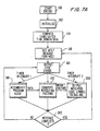
- FIG. 2 An embodiment of a digital encoder is illustrated in Figure 2 .
- an audio signal in analog form is received at an input terminal 60 and converted to digital form by an A/D converter 62.
- the digitized audio signal is supplied for masking evaluation, as indicated functionally by the block 64 pursuant to which the digitized audio signal is separated into frequency components, for example, by Fast Fourier Transform (FFT), wavelet transform, or other time-to-frequency domain transformation, or else by digital filtering.
- FFT Fast Fourier Transform
- wavelet transform wavelet transform
- other time-to-frequency domain transformation or else by digital filtering.
- the masking abilities of audio signal frequency components within frequency bins of interest are evaluated for their tonal masking ability, narrow band masking ability and broadband masking ability (and, if necessary or appropriate, for non-simultaneous masking ability).
- the masking abilities of audio signal frequency components within frequency bins of interest are evaluated with a sliding tonal analysis.
- Data to be encoded is received at an input terminal 68 and, for each data state corresponding to a given signal interval, its respective group of code components is produced, as indicated by the signal generation functional block 72, and subjected to level adjustment, as indicated by the block 76 which is also supplied with the relevant masking evaluations.
- Signal generation may be implemented, for example, by means of a look-up table storing each of the code components as time domain data or by interpolation of stored data.
- the code components can either be permanently stored or generated upon initialization of the system of Figure 2 and then stored in memory, such as in RAM, to be output as appropriate in response to the data received at terminal 68.
- the values of the components may also be computed at the time they are generated.
- Level adjustment is carried out for each of the code components based upon the relevant masking evaluations as discussed above, and the code components whose amplitude has been adjusted to ensure inaudibility are added to the digitized audio signal as indicated by the summation symbol 80.
- an amplitude may be assigned to the code component based on the non-simultaneous masking abilities of the portion of audio signal within the first interval. In this fashion both simultaneous and non-simultaneous masking capabilities may be evaluated and an optimal amplitude can be assigned to each code component based on the more advantageous evaluation.
- the encoded audio signal in digital form is converted to analog form by a digital-to-analog converter (DAC) 84.
- DAC digital-to-analog converter
- the DAC 84 may be omitted.
- FIG. 2 The various functions illustrated in Figure 2 may be implemented, for example, by a digital signal processor or by a personal computer, workstation, mainframe, or other digital computer.
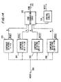
- FIG. 3 is a block diagram of an encoding system for use in encoding audio signals supplied in analog form, such as in a conventional broadcast studio.
- a host processor 90 which may be, for example, a personal computer, supervises the selection and generation of information to be encoded for inclusion in an analog audio signal received at an input terminal 94.
- the host processor 90 is coupled with a keyboard 96 and with a monitor 100, such as a CRT monitor, so that a user may select a desired message to be encoded while choosing from a menu of available messages displayed by the monitor 100.
- a typical message to be encoded in a broadcast audio signal could include station or channel identification information, program or segment information and/or a time code.
- the host proceeds to output data representing the symbols of the message to a digital signal processor (DSP) 104 which proceeds to encode each symbol received from the host processor 90 in the form of a unique set of code signal components as described hereinbelow.
- DSP digital signal processor
- the host processor generates a four state data stream, that is, a data stream in which each data unit can assume one of four distinct data states each representing a unique symbol including two synchronizing symbols termed "E" and "S” herein and two message information symbols "1" and "0” each of which represents a respective binary state.
- E synchronizing symbols
- S two message information symbols
- any number of distinct data states may be employed.
- three data states may be represented by three unique symbols which permits a correspondingly larger amount of information to be conveyed by a data stream of a given size.
- the program material represents speech
- the number of possible message information symbols is advantageously increased. For symbols representing up to five bits, symbol transmission lengths of two, three and four seconds provide increasingly greater probabilities of correct decoding.
- an initial symbol (“E") is decoded when (i) the energy in the FFT bins for this symbol is greatest, (ii) the average energy minus the standard deviation of the energy for this symbol is greater than the average energy plus the average standard deviation of the energy for all other symbols, and (iii) the shape of the energy versus time curve for this symbol has a generally bell shape, peaking at the intersymbol temporal boundary.
- the DSP 104 As the DSP 104 has received the symbols of a given message to be encoded, it responds by generating a unique set of code frequency components for each symbol which it supplies at an output 106.
- spectral diagrams are provided for each of the four data symbols S, E, 0 and 1 of the exemplary data set described above.
- the symbol S is represented by a unique group of ten code frequency components f 1 through f 10 arranged at equal frequency intervals in a range extending from a frequency value slightly greater than 2 kHz to a frequency value slightly less than 3 kHz.
- the symbol E is represented by a second unique group of ten code frequency components f 11 through f 20 arranged in the frequency spectrum at equal intervals from a first frequency value slightly greater than 2 kHz up to a frequency value slightly less than 3 kHz, wherein each of the code components f 11 through f 20 has a unique frequency value different from all others in the same group as well as from all of the frequencies f 1 through f 10 .
- the symbol 0 is represented by a further unique group of ten code frequency components f 21 through f 30 also arranged at equal frequency intervals from a value slightly greater than 2 kHz up to a value slightly less than 3 kHz and each of which has a unique frequency value different from all others in the same group as well as from all of the frequencies f 1 through f 20 .
- the symbol 1 is represented by a further unique group of ten code frequency components f 31 through f 40 also arranged at equal frequency intervals from a value slightly greater than 2 kHz to a value slightly less than 3 kHz, such that each of the components f 31 through f 40 has a unique frequency value different from any of the other frequency components f 1 through f 40 .
- the presence of noise (such as non-code audio signal components or other noise) in a common detection band with any one code component of a given data state is less likely to interfere with detection of the remaining components of that data state.
- each code frequency component of each symbol is paired with a frequency component of each of the other data states so that the difference therebetween is less than the critical bandwidth therefor.
- the critical bandwidth is a frequency range within which the frequency separation between the two tones may be varied without substantially increasing loudness.
- each tone of each of the data states S, E, O and 1 is paired with a respective tone of each of the others thereof so that the difference in frequency therebetween is less than the critical bandwidth for that pair, there will be substantially no change in loudness upon transition from any of the data states S, E, 0 and 1 to any of the others thereof when they are reproduced as sound.
- the relative probabilities of detecting each data state when it is received is not substantially affected by the frequency characteristics of the transmission path.
- a further benefit of pairing components of different data states so that they are relatively close in frequency is that a masking evaluation carried out for a code component of a first data state will be substantially accurate for a corresponding component of a next data state when switching of states take place.
- the frequencies selected for each of the code frequency components f 1 through f 10 are clustered around a frequency, for example, the frequency components for f1, f2 and f3 are located in the vicinity of 1055 Hz, 1180 Hz and 1340 Hz, respectively.
- the tones are spaced apart by two times the FFT resolution, for example, for a resolution of 4 Hz, the tones are shown as spaced apart by 8 Hz, and are chosen to be in the middle of the frequency range of an FFT bin.
- the order of the various frequencies which are assigned to the code frequency components f 1 through f 10 for representing the various symbols 0, 1, S and E is varied in each cluster.
- the frequencies selected for the components f1, f2 and f3 correspond to the symbols (0, 1, S, E), (S, E, 0, 1) and (E, S, 1, 0), respectively, from lowest to highest frequency, that is, (1046.9, 1054.7, 1062.5, 1070.3), (1179.7, 1187.5, 1195.3, 1203.1), (1328.1, 1335.9, 1343.8, 1351.6).
- a benefit of this scheme is that even if there is a room null which interferes with correct reception of a code component, in general the same tone is eliminated from each of the symbols, so it is easier to decode a symbol from the remaining components. In contrast, if a room null eliminates a component from one symbol but not from another symbol, it is more difficult to correctly decode the symbol.
- each data state or symbol may be represented by more or less than ten code tones, and while it is preferable that the same number of tones be used to represent each of the data states, it is not essential in all applications that the number of code tones used to represent each data state be the same.
- each of the code tones differs in frequency from all of the other code tones to maximize the probability of distinguishing each of the data states upon decoding.
- FIG. 5 is a functional block diagram to which reference is made in explaining the encoding operation carried out by the embodiment of Figure 3 .
- the DSP 104 receives data from the host processor 90 designating the sequence of data states to be output by the DSP 104 as respective groups of code frequency components.
- the DSP 104 generates a look-up table of time domain representations for each of the code frequency components f 1 through f 40 which it then stores in a RAM thereof, represented by the memory 110 of Figure 5 .
- the DSP 104 In response to the data received from the host processor 90, the DSP 104 generates a respective address which it applies to an address input of the memory 110, as indicated at 112 in Figure 5 , to cause the memory 110 to output time domain data for each of the ten frequency components corresponding to the data state to be output at that time.
- the memory 110 stores a sequence of time-domain values for each of the frequency components of each of the symbols S, E, 0 and 1.
- the code frequency components range from approximately 2 kHz up to approximately 3 kHz
- a sufficiently large number of time domain samples are stored in the memory 110 for each of the frequency components f 1 through f 40 so that they may be output at a rate higher than the Nyquist frequency of the highest frequency code component.
- the time domain code components are output at an appropriately high rate from the memory 110 which stores time-domain components for each of the code frequency components representing a predetermined duration so that (n) time-domain components are stored for each of the code frequency components f 1 through f 40 for (n) time intervals t 1 through t n , as shown in Figure 6 .
- the memory 110 outputs the time-domain components f 1 through f 10 corresponding to that interval, as stored in the memory 110.
- the time-domain components f 1 through f 10 for the interval t 2 are output by the memory 110. This process continues sequentially for the intervals t 3 through t n and back to t 1 until the duration of the encoded symbol S has expired.
- the DSP 104 also serves to adjust the amplitudes of the time-domain components output by the memory 110 so that, when the code frequency components are reproduced as sound, they will be masked by components of the audio signal in which they have been included such that they are inaudible to human hearing. Consequently, the DSP 104 is also supplied with the audio signal received at the input terminal 94 after appropriate filtering and analog-to-digital conversion. More specifically, the encoder of Figure 3 includes an analog band pass filter 120 which serves to substantially remove audio signal frequency components outside of a band of interest for evaluating the masking ability of the received audio signal which in the present embodiment extends from approximately 1.5 kHz to approximately 3.2 kHz. The filter 120 also serves to remove high frequency components of the audio signal which may cause aliasing when the signal is subsequently digitized by an analog-to-digital convertor (A/D) 124 operating at a sufficiently high sampling rate.
- A/D analog-to-digital convertor
- the digitized audio signal is supplied by the A/D 124 to DSP 104 where, as indicated at 130 in Figure 5 , the program audio signal undergoes frequency range separation.
- frequency range separation is carried out as a Fast Fourier Transform (FFT) which is performed periodically with or without temporal overlap to produce successive frequency bins each having a predetermined frequency width.
- FFT Fast Fourier Transform
- Other techniques are available for segregating the frequency components of the audio signals, such as a wavelet transform, discrete Walsh Hadamard transform, discrete Hadamard transform, discrete cosine transform, as well as various digital filtering techniques.
- the DSP 104 After the DSP 104 has separated the frequency components of the digitized audio signal into the successive frequency bins, as mentioned above, it then proceeds to evaluate the ability of various frequency components present in the audio signal to mask the various code components output by the memory 110 and to produce respective amplitude adjustment factors which serve to adjust the amplitudes of the various code frequency components such that they will be masked by the program audio when reproduced as sound so that they will be inaudible to human hearing. These processes are represented by the block 134 in Figure 5 .
- the masking ability of the program audio components is evaluated on a tonal basis, as well as on a narrow band masking basis and on a broadband masking basis, as described below.
- a tonal masking ability is evaluated for each of a plurality of audio signal frequency components based on the energy level in each of the respective bins in which these components fall as well as on the frequency relationship of each bin to the respective code frequency component.
- the evaluation in each case may take the form of an amplitude adjustment factor or other measure enabling a code component amplitude to be assigned so that the code component is masked by the audio signal.
- the evaluation may be a sliding tonal analysis.
- narrow band masking in this embodiment for each respective code frequency component the energy content of frequency components below a predetermined level within a predetermined frequency band including the respective code frequency component is evaluated to derive a separate masking ability evaluation.
- narrow band masking capability is measured based on the energy content of those audio signal frequency components below the average bin energy level within the predetermined frequency band.
- the energy levels of the components below the energy levels of the components below the average bin energy are summed to produce a narrow band energy level in response to which a corresponding narrow band masking evaluation for the respective code component is identified.
- a different narrow band energy level may instead be produced by selecting a component threshold other than the average energy level.
- the average energy level of all audio signal components within the predetermined frequency band instead is used as the narrow band energy level for assigning a narrow band masking evaluation to the respective code component.
- the total energy content of audio signal components within the predetermined frequency band instead is used, while in other embodiments a minimum component level within the predetermined frequency band is used for this purpose.
- the broadband energy content of the audio signal is determined to evaluate the ability of the audio signal to mask the respective code frequency component on a broadband masking basis.
- the broadband masking evaluation is based on the minimum narrow band energy level found in the course of the narrow band masking evaluations described above. That is, if four separate predetermined frequency bands have been investigated in the course of evaluating narrow band masking as described above, and broadband noise is taken to include the minimum narrow band energy level among all four predetermined frequency bands (however determined), then this minimum narrow band energy level is multiplied by a factor equal to the ratio of the range of frequencies spanned by all four narrow bands to the bandwidth of the predetermined frequency band having the minimum narrow band energy level. The resulting product indicates a permissible overall code power level.
- each is then assigned an amplitude adjustment factor to yield a component power level which is 10 dB less than P.
- broadband noise is calculated for a predetermined, relatively wide band encompassing the code components by selecting one of the techniques discussed above for assessing the narrow band energy level but instead using the audio signal components throughout the predetermined, relatively wide band. Once the broadband noise has been determined in the selected manner, a corresponding broadband masking evaluation is assigned to each respective code component.
- the amplitude adjust factor for each code frequency component is then selected based upon that one of the tonal, narrow band and broadband masking evaluations yielding the highest permissible level for the respective component. This maximizes the probability that each respective code frequency component will be distinguishable from non-audio signal noise while at the same time ensuring that the respective code frequency component will be masked so that it is inaudible to human hearing.
- the amplitude adjust factors are selected for each of tonal, narrow band and broadband masking based on the following factors and circumstances.
- the factors are assigned on the basis of the frequencies of the audio signal components whose masking abilities are being evaluated and the frequency or frequencies of the code components to be masked.
- a given audio signal over any selected interval provides the ability to mask a given code component within the same interval (i.e., simultaneous masking) at a maximum level greater than that at which the same audio signal over the selected interval is able to mask the same code component occurring before or after the selected interval (i.e., non-simultaneous masking).
- the conditions under which the encoded audio signal will be heard by an audience or other listening group, as appropriate, preferably are also taken into consideration. For example, if television audio is to be encoded, the distorting effects of a typical listening environment are preferably taken into consideration, since in such environments certain frequencies are attenuated more than others. Receiving and reproduction equipment (such as graphic equalizers) can cause similar effects. Environmental and equipment related effects can be compensated by selecting sufficiently low amplitude adjust factors to ensure masking under anticipated conditions.
- tonal, narrow band or broadband masking capabilities are evaluated. In other embodiments two of such different types of masking capabilities are evaluated, and in still others all three are employed.
- a sliding tonal analysis is employed to evaluate the masking capability of the audio signal.
- a sliding tonal analysis generally satisfies the masking rules for narrow band noise, broadband noise and single tones without requiring audio signal classification.
- the audio signal is regarded as a set of discrete tones, each being centered in a respective FFT frequency bin.
- the sliding tonal analysis first computes the power of the audio signal in each FFT bin. Then, for each code tone, the masking effects of the discrete tones of the audio signal in each FFT bin separated in frequency from such code tone by no more than the critical bandwidth of the audio tone are evaluated based on the audio signal power in each such bin using the masking relationships for single tone masking.
- the masking effects of all of the relevant discrete tones of the audio signal are summed for each code tone, then adjusted for the number of tones within the critical bandwidth of the audio signal tones and the complexity of the audio signal.
- the complexity of the program material is empirically based on the ratio of the power in the relevant tones of the audio signal and the root sum of squares power in such audio signal tones. The complexity serves to account for the fact that narrow band noise and broadband noise each provide much better masking effects than are obtained from a simple summation of the tones used to model narrow band and broadband noise.
- a predetermined number of samples of the audio signal first undergo a large FFT, which provides high resolution but requires longer processing time. Then, successive portions of the predetermined number of samples undergo a relatively smaller FFT, which is faster but provides less resolution. The amplitude factors found from the large FFT are merged with those found from the smaller FFTs, which generally corresponds to time weighting the higher "frequency accuracy” large FFT by the higher "time accuracy” of the smaller FFT.
- each code frequency component is initially generated so that its amplitude conforms to its respective adjust factor.
- the amplitude adjust operation of the DSP 104 in this embodiment multiplies the ten selected ones of the time domain code frequency components values f 1 through f 40 for the current time interval t 1 through t n by a respective amplitude adjust factor G A1 through G A10 and then the DSP 104 proceeds to add the amplitude adjusted time domain components to produce a composite code signal which it supplies at its output 106.
- the composite code signal is converted to analog form by a digital-to-analog converter (DAC) 140 and supplied thereby to a first input of a summing circuit 142.
- the summing circuit 142 receives the audio signal from the input terminal 94 at a second input and adds the composite analog code signal to the analog audio signal to supply an encoded audio signal at an output 146 thereof.
- the encoded audio signal modulates a carrier wave and is broadcast over the air.
- the encoded audio signal frequency modulates a subcarrier and is mixed with a composite video signal so that the combined signal is used to modulate a broadcast carrier for over-the-air broadcast.
- the radio and television signals may also be transmitted by cable (for example, conventional or fiber optic cable), satellite or otherwise.
- the encoded audio can be recorded either for distribution in recorded form or for subsequent broadcast or other wide dissemination. Encoded audio may also be employed in point-to-point transmissions.
- Figures 7A through 7C provide flow charts for illustrating a software routine carried out by the DSP 104 for implementing the evaluation of tonal, narrow band and broadband masking functions thereof described above.
- Figure 7A illustrates a main loop of the software program of the DSP 104.
- the program is initiated by a command from the host processor 90 (step 150), whereupon the DSP 104 initializes its hardware registers (step 152) and then proceeds in step 154 to compute unweighted time domain code component data as illustrated in Figure 6 which it then stores in memory to be read out as needed to generate the time domain code components, as mentioned hereinabove.
- this step may be omitted if the code components are stored permanently in a ROM or other nonvolatile storage. It is also possible to calculate the code component data when required, although this adds to the processing load.
- Another alternative is to produce unweighted code components in analog form and then adjust the amplitudes of the analog components by means of weighting factors produced by a digital processor.
- the DSP 104 communicates a request to the host processor 90 for a next message to be encoded.
- the message is a string of characters, integers, or other set of data symbols uniquely identifying the code component groups to be output by the DSP 104 in an order which is predetermined by the message.
- the host knowing the output data rate of the DSP, determines on its own when to supply a next message to the DSP by setting an appropriate timer and supplying the message upon a time-out condition.
- a decoder is coupled with the output of the DSP 104 to receive the output code components in order to decode the same and feed back the message to the host processor as output by the DSP so that the host can determine when to supply a further message to the DSP 104.
- the functions of the host processor 90 and the DSP 104 are carried out by a single processor.
- the DSP proceeds to generate the code components for each symbol of the message in order and to supply the combined, weighted code frequency components at its output 106. This process is represented by a loop identified by the tag 160 in Figure 7A .
- the DSP 104 Upon entering the loop symbolized by the tag 160, the DSP 104 enables timer interrupts 1 and 2 and then enters a "compute weighting factors" subroutine 162 which will be described in connection with the flow charts of Figures 7B and 7C .
- the DSP upon entering the compute weighting factors subroutine 162 the DSP first determines whether a sufficient number of audio signal samples have been stored to permit a high-resolution FFT to be carried out in order to analyze the spectral content of the audio signal during a most recent predetermined audio signal interval, as indicated by step 163. Upon start up, a sufficient number of audio signal samples must first be accumulated to carry out the FFT. However, if an overlapping FFT is employed, during subsequent passes through the loop correspondingly fewer data samples need be stored before the next FFT is carried out.
- the DSP remains in a tight loop at the step 163 awaiting the necessary sample accumulation.
- the A/D 124 provides a new digitized sample of the program audio signal which is accumulated in a data buffer of the DSP 104, as indicated by the subroutine 164 in Figure 7A .
- step 168 wherein the above-mentioned high resolution FFT is carried out on the audio signal data samples of the most recent audio signal interval. Thereafter, as indicated by a tag 170, a respective weighting factor or amplitude adjust factor is computed for each of the ten code frequency components in the symbol currently being encoded.
- step 172 that one of the frequency bins produced by the high resolution FFT (step 168) which provides the ability to mask the highest level of the respective code component on a single tone basis (the "dominant tonal") is determined in the manner discussed above.
- the weighting factor for the dominant tonal is determined and retained for comparison with relative masking abilities provided by narrow band and broadband masking and, if found to be the most effective masker, is used as the weighting factor for setting the amplitude of the current code frequency component.
- an evaluation of narrow band and broadband masking capabilities is carried out in the manner described above.
- a subsequent step 186 it is determined whether broadband masking provides the best ability to mask the respective code frequency component and, if so, in a step 190, the weighting factor for the respective code frequency component is adjusted based on broadband masking. Then, in step 192 it is determined whether weighting factors have been selected for each of the code frequency components to be output presently to represent the current symbol and, if not, the loop is reinitiated to select a weighting factor for the next code frequency component. If, however, the weighting factors for all components have been selected, then the subroutine is terminated as indicated in step 194.
- processing continues to a subroutine 200 wherein the functions illustrated in Figure 6 above are carried out. That is, in the subroutine 200 the weighting factors calculated during the subroutine 162 are used to multiply the respective time domain values of the current symbol to be output and then the weighted time domain code component values are added and output as a weighted, composite code signal to the DAC 140. Each code symbol is output for a predetermined period of time upon the expiration of which processing returns to the step 156 from the step 202.
- Figures 7D and 7E show flowcharts illustrating an implementation of the sliding tonal analysis technique for evaluating the masking effects of an audio signal.
- variables are initialized such as the size in samples of a large FFT and a smaller FFT, the number of smaller FFTs per large FFT and the number of code tones per symbol, for example, 2048, 256, 8 and 10, respectively.
- a number of samples corresponding to a large FFT is analyzed.
- audio signal samples are obtained.
- the power of the program material in each FFT bin is obtained.
- the permissible code tone power in each corresponding FFT bin accounting for the effects of all of the relevant audio signal tones on that bin, is obtained, for each of the tones.
- the flowchart of Figure 7E shows step 708 in more detail.
- steps 710-712 a number of samples corresponding to a smaller FFT is analyzed, in similar fashion to steps 706-708 for a large FFT.
- the permissible code powers found from the large FFT in step 708 and the smaller FFT in step 712 are merged for the portion of the samples which have undergone a smaller FFT.
- the code tones are mixed with the audio signal to form encoded audio, and at step 718, the encoded audio is output to DAC 140.
- Figure 7E provides detail for steps 708 and 712, computing the permissible code power in each FFT bin.
- this procedure models the audio signal as comprising a set of tones (see examples below), computes the masking effect of each audio signal tone on each code tone, sums the masking effects and adjusts for the density of code tones and complexity of the audio signal.
- the band of interest is determined. For example, let the bandwidth used for encoding be 800 Hz - 3200 Hz, and the sampling frequency be 44100 samples/sec. The starting bin begins at 800 Hz, and the ending bin ends at 3200 Hz.
- the masking effect of each relevant audio signal tone on each code in this bin is determined using the masking curve for a single tone, and compensating for the non-zero audio signal FFT bin width by determining (1) a first masking value based on the assumption that all of the audio signal power is at the upper end of the bin, and (2) a second masking value based on the assumption that all of the audio signal power is at the lower end of the bin, and then choosing that one of the first and second masking values which is smaller.
- Figure 7F shows an approximation of a single tone masking curve for an audio signal tone at a frequency of fPGM which is about 2200 Hz in this example, following Zwislocki, J. J., "Masking: Experimental and Theoretical Aspects of Simultaneous, Forward, Backward and Central Masking", 1978, in Zwicker et al., ed., Psychoacoustics: Facts and Models, pages 283-316, Springer-Verlag, New York .
- a first mfactor is computed based on the assumption that all of the audio signal power is at the lower end of its bin, then a second mfactor is computed assuming that all of the audio signal power is at the upper end of its bin, and the smaller of the first and second mfactors is chosen as the masking value provided by that audio signal tone for the selected code tone.
- this processing is performed for each relevant audio signal tone for each code tone.
- each code tone is adjusted by each of the masking factors corresponding to the audio signal tones.
- the masking factor is multiplied by the audio signal power in the relevant bin.
- step 758 the result of multiplying the masking factors by the audio signal power is summed for each bin, to provide an allowable power for each code tone.
- the allowable code tone powers are adjusted for the number of code tones within a critical bandwidth on either side of the code tone being evaluated, and for the complexity of the audio signal.
- the number of code tones within the critical band, CTSUM is counted.
- PSUM is the sum of the masking tone power levels assigned to the masking of the code tone whose ADJFAC is being determined.
- PRSS measures masking power peakiness (increasing values) or spread-out-ness (decreasing values) of the program material.
- step 762 of Figure 7E it is determined whether there are any more bins in the band of interest, and if so, they are processed as described above.
- the breakpoints for the curve of Figure 7F are at 2500 ⁇ 0.3*350 or 2395 and 2605 Hz.
- tonal masking is calculated according to the single tone method explained above in conjunction with Figure 7F .
- narrow band noise masking is calculated by first computing the average power across a critical band centered on the frequency of the code tone of interest. Tonals with power greater than the average power are not considered as part of the noise and are removed. The summation of the remaining power is the narrow band noise power.
- the maximum allowable code tone power is -6 dB of the narrow band noise power for all code tones within a critical bandwidth of the code tone of interest.
- broadband noise masking is calculated by calculating the narrow band noise power for critical bands centered at 2000, 2280, 2600 and 2970 Hz.
- the allowed code tone power is -3 dB of the broadband noise power. When there are ten code tones, the maximum power allowed for each is 10 dB less, or -13 dB of the broadband noise power.
- the sliding tonal analysis calculations are seen to generally correspond to the "Best of 3" calculations, indicating that the sliding tonal analysis is a robust method. Additionally, the results provided by the sliding tonal analysis in the case of multiple tones are better, that is, allow larger code tone powers, than in the "Best of 3” analysis, indicating that the sliding tonal analysis is suitable even for cases which do not fit neatly into one of the "Best of 3” calculations.
- an embodiment of an encoder which employs analog circuitry is shown in block form therein.
- the analog encoder receives an audio signal in analog form at an input terminal 210 from which the audio signal is supplied as an input to N component generator circuits 220 1 through 220 N each of which generates a respective code component C 1 through C N .
- component generator circuits 220 1 and 220 N are shown in Figure 8 .
- each of the component generator circuits is supplied with a respective data input terminal 222 1 through 222 N which serves as an enabling input for its respective component generator circuit.
- Each symbol is encoded as a subset of the code components C 1 through C N by selectably applying an enabling signal to certain ones of the component generator circuits 220 1 through 220 N .
- the generated code components corresponding with each data symbol are supplied as inputs to a summing circuit 226 which receives the input audio signal from the input terminal 210 at a further input, and serves to add the code components to the input audio signal to produce the encoded audio signal which it supplies at an output thereof.
- Each of the component generator circuits is similar in construction and includes a respective weighting factor determination circuit 230 1 through 230 N , a respective signal generator 232 1 through 232 N , and a respective switching circuit 234 1 through 234 N .
- Each of the signal generators 232 1 through 232 N produces a respectively different code component frequency and supplies the generated component to the respective switching circuit 234 1 through 234 N , each of which has a second input coupled to ground and an output coupled with an input of a respective one of multiplying circuits 236 1 through 236 N .
- each of the switching circuits 234 1 through 234 N responds by coupling the output of its respective signal generator 232 1 through 232 N to the input of the corresponding one of multiplying circuits 236 1 through 236 N .
- each switching circuit 234 1 through 234 N couples its output to the grounded input so that the output of the corresponding multiplier 236 1 through 236 N is at a zero level.
- Each weighting factor determination circuit 230 1 through 230 N serves to evaluate the ability of frequency components of the audio signal within a corresponding frequency band thereof to mask the code component produced by the corresponding generator 232 1 to 232 N to produce a weighting factor which it supplies as an input to the corresponding multiplying circuit 236 1 through 236 N in order to adjust the amplitude of the corresponding code component to ensure that it will be masked by the portion of the audio signal which has been evaluated by the weighting factor determination circuit.
- the construction of each of the weighting factor determination circuits 230 1 through 230 N is illustrated in block form.
- the circuit 230 includes a masking filter 240 which receives the audio signal at an input thereof and serves to separate the portion of the audio signal which is to be used to produce a weighting factor to be supplied to the respective one of the multipliers 236 1 through 236 N .
- the characteristics of the masking filter are selected to weight the amplitudes of the audio signal frequency components i according to their relative abilities to mask the respective code component.
- the portion of the audio signal selected by the masking filter 240 is supplied to an absolute value circuit 242 which produces an output representing an absolute value of a portion of the signal within the frequency band passed by the masking filter 240.
- the output of the absolute value circuit 242 is supplied as an input to a scaling amplifier 244 having a gain selected to produce an output signal which, when multiplied by the output of the corresponding switch 234 1 through 234 N , will produce a code component at the output of the corresponding multiplier 236 1 through 236 N which will ensure that the multiplied code component will be masked by the selected portion of the audio signal passed by the masking filter 240 when the encoded audio signal is reproduced as sound.
- Each weighting factor determination circuit 230 1 through 230 N therefore, produces a signal representing an evaluation of the ability of the selected portion of the audio signal to mask the corresponding code component.
- multiple weighting factor determination circuits are supplied for each code component generator, and each of the multiple weighting factor determination circuits corresponding to a given code component evaluates the ability of a different portion of the audio signal to mask that particular component when the encoded audio signal is reproduced as sound.
- a plurality of such weighting factor determination circuits may be supplied each of which evaluates the ability of a portion of the audio signal within a relatively narrow frequency band (such that audio signal energy within such band will in all likelihood consist of a single frequency component) to mask the respective code component when the encoded audio is reproduced as sound.
- a further weighting factor determination circuit may also be supplied for the same respective code component for evaluating the ability of audio signal energy within a critical band having the code component frequency as a center frequency to mask the code component when the encoded audio signal is reproduced as sound.
- the various elements of the Figures 8 and 9 embodiment are implemented by analog circuits, it will be appreciated that the same functions carried out by such analog circuits may also be implemented, in whole or in part, by digital circuitry.
- Decoders and decoding methods which are especially adapted for decoding audio signals encoded by the inventive techniques disclosed hereinabove, as well as generally for decoding codes included in audio signals such that the codes may be distinguished therefrom based on amplitude, will now be described.
- the presence of one or more code components in an encoded audio signal is detected by establishing an expected amplitude or amplitudes for the one or more code components based on either or both of the audio signal level and a non-audio signal noise level as indicated by the functional block 250.
- One or more signals representing such expected amplitude or amplitudes are supplied, as at 252 in Figure 10 , for determining the presence of the code component by detecting a signal corresponding to the expected amplitude or amplitudes as indicated by the functional block 254.
- Decoders in accordance with the present invention are particularly well adapted for detecting the presence of code components which are masked by other components of the audio signal since the amplitude relationship between the code components and the other audio signal components is, to some extent, predetermined.
- FIG. 11 is a block diagram of a decoder in accordance with an embodiment of the present invention which employs digital signal processing for extracting codes from encoded audio signals received by the decoder in analog form.
- the decoder of Figure 11 has an input terminal 260 for receiving the encoded analog audio signal which may be, for example, a signal picked up by a microphone and including television or radio broadcasts reproduced as sound by a receiver, or else such encoded analog audio signals provided in the form of electrical signals directly from such a receiver.
- Such encoded analog audio may also be produced by reproducing a sound recording such as a compact disk or tape cassette.
- Analog conditioning circuits 262 are coupled with the input 260 to receive the encoded analog audio and serve to carry out signal amplification, automatic gain control and anti-aliasing low-pass filtering prior to analog-to-digital conversion. In addition, the analog conditioning circuits 262 serve to carry out a bandpass filtering operation to ensure that the signals output thereby are limited to a range of frequencies in which the code components can appear.
- the analog conditioning circuits 262 output the processed analog audio signals to an analog-to-digital converter (A/D) 263 which converts the received signals to digital form and supplies the same to a digital signal processor (DSP) 266 which processes the digitized analog signals to detect the presence of code components and determines the code symbols they represent.
- A/D analog-to-digital converter
- DSP digital signal processor
- the digital signal processor 266 is coupled with a memory 270 (comprising both program and data storage memories) and with input/output (I/O) circuits 272 to receive external commands (for example, a command to initiate decoding or a command to output stored codes) and to output decoded messages.
- a memory 270 comprising both program and data storage memories
- I/O input/output circuits 272 to receive external commands (for example, a command to initiate decoding or a command to output stored codes) and to output decoded messages.
- the analog conditioning circuits 262 serve to bandpass filter the encoded audio signals with a passband extending from approximately 1.5 kHz to 3.1 kHz and the DSP 266 samples the filtered analog signals at an appropriately high rate.
- the digitized audio signal is then separated by the DSP 266 into frequency component ranges or bins by FFT processing. More specifically, an overlapping, windowed FFT is carried out on a predetermined number of the most recent data points, so that a new FFT is performed periodically upon receipt of a sufficient number of new samples.
- the data are weighted as discussed below and the FFT is performed to produce a predetermined number of frequency bins each having a predetermined width.
- the energy B(i) of each frequency bin in a range encompassing the code component frequencies is computed by the DSP 266.
- a signal-to-noise ratio for that bin SNR(j) is estimated by dividing the energy level B(j) in the bin of interest by the estimated noise level NS(j).
- the values of SNR(j) are employed both to detect the presence and timing of synchronization symbols as well as the states of data symbols, as discussed below.
- Various techniques may be employed to eliminate audio signal components from consideration as code components on a statistical basis. For example, it can be assumed that the bin having the highest signal to noise ratio includes an audio signal component. Another possibility is to exclude those bins having an SNR(j) above a predetermined value. Yet another possibility is to eliminate from consideration those bins having the highest and/or the lowest SNR(j).
- the apparatus of Figure 11 When used to detect the presence of codes in audio signals encoded by means of the apparatus of Figure 3 , the apparatus of Figure 11 accumulates data indicating the presence of code components in each of the bins of interest repeatedly for at least a major portion of the predetermined interval in which a code symbol can be found. Accordingly, the foregoing process is repeated multiple times and component presence data is accumulated for each bin of interest over that time frame. Techniques for establishing appropriate detection time frames based on the use of synchronization codes will be discussed in greater detail hereinbelow. Once the DSP 266 has accumulated such data for the relevant time frame, it then determines which of the possible code signals was present in the audio signal in the manner discussed below.
- the DSP 266 then stores the detected code symbol in the memory 270 together with a time stamp for identifying the time at which the symbol was detected based on an internal clock signal of the DSP. Thereafter, in response to an appropriate command to the DSP 266 received via the I/O circuit 272, the DSP causes the memory 270 to output the stored code symbols and time stamps via the I/O circuits 272.
- the flow charts of Figures 12A and 12B illustrate the sequence of operations carried out by the DSP 266 in decoding a symbol encoded in the analog audio signal received at the input terminal 260.
- the DSP 266 upon initiation of the decoding process, the DSP 266 enters a main program loop at a step 450 in which it sets a flag SYNCH so that the DSP 266 first commences an operation to detect the presence of the sync symbols E and S in the input audio signal in a predetermined message order.
- step 450 is carried out the DSP 266 calls a sub-routine DET, which is illustrated in the flow chart of Figure 12B to search for the presence of code components representing the sync symbols in the audio signal.
- the DSP gathers and stores samples of the input audio signal repeatedly until a sufficient number has been stored for carrying out the FFT described above.
- the stored data are subjected to a weighting function, such as a cosine squared weighting function, Kaiser-Bessel function, Gaussian (Poisson) function, Hanning function or other appropriate weighting function, as indicated by the step 456, for windowing the data.
- a weighting function such as a cosine squared weighting function, Kaiser-Bessel function, Gaussian (Poisson) function, Hanning function or other appropriate weighting function.
- a weighting function such as a cosine squared weighting function, Kaiser-Bessel function, Gaussian (Poisson) function, Hanning function or other appropriate weighting function
- a step 462 the SYNCH flag is tested to see if it is set (in which case a sync symbol is expected) or reset (in which case a data bit symbol is expected). Since initially the DSP sets the SYNCH flag to detect the presence of code components representing sync symbols, the program progresses to a step 466 wherein the frequency domain data obtained by means of the FFT of step 460 is evaluated to determine whether such data indicates the presence of components representing an E sync symbol or an S sync symbol.
- the detection threshold is produced as an average of the values SNR(j) for all forty of the frequency bins of interest, but can be adjusted by a multiplication factor to account for the effects of ambient noise and/or to compensate for an observed error rate.
- the program returns to the main processing loop of. Figure 12A at a step 472 where it is determined (as explained hereinbelow) whether a pattern of the decoded data satisfies predetermined qualifying criteria.
- processing returns to the step 450 to recommence a search for the presence of a sync symbol in the audio signal, but if such criteria are met, it is determined whether the expected sync pattern (that is, the expected sequence of symbols E and S) has been received in full and detected, as indicated by the step 474.
- the expected sync pattern that is, the expected sequence of symbols E and S
- step 474 processing returns to the sub-routine DET to carry out a further FFT and evaluation for the presence of a sync symbol.
- the DSP determines whether the accumulated data satisfies the qualifying criteria for a sync pattern.
- the evaluation process carried out in the step 472 after the sub-routine DET 452 continues each time using the same number of evaluations from the step 466, but discarding the oldest evaluation and adding the newest, so that a sliding data window is employed for this purpose.
- a cross-over from the "E" symbol to the "S” is determined in one embodiment as the point where the total of "S" bin SNR's resulting from the step 466 within the sliding window first exceeds the total of "E" bin SNR's during the same interval.
- processing continues in the manner described above to search for a maximum of the "S" symbol energy which is indicated by the greatest number of "S" detections within the sliding data window. If such a maximum is not found or else the maximum does not occur within an expected time frame after the maximum of the "E" symbol energy, processing proceeds from the step 472 back to the step 450 to recommence the search for a sync pattern.
- a sync pattern which does not satisfy criteria such as those described above but which approximates a qualifying pattern (that is, the detected pattern is not clearly non-qualifying)
- a determination whether the sync pattern has been detected may be postponed pending further analysis based upon evaluations carried out (as explained herein- below) to determine the presence of data bits in expected data intervals following the potential sync pattern. Based on the totality of the detected data, that is, both during the suspected sync pattern interval and during the suspected bit intervals, a retrospective qualification of the possible sync pattern may be carried out.
- the bit timing is determined based upon the two maxima and the cross-over point. That is, these values are averaged to determine the expected start and end points of each subsequent data bit interval.
- the SYNCH flag is reset to indicate that the DSP will then search for the presence of either possible bit state.
- the sub-routine DET 452 is again called and, with reference to Figure 12B as well, the sub-routine is carried out in the same fashion as described above until the step 462 wherein the state of the SYNCH flag indicates that a bit state should be determined and processing proceeds then to a step 486.
- the DSP searches for the presence of code components indicating either a zero bit state or a one bit state in the manner described hereinabove.
- processing returns to the main processing loop of Figure 12A in a step 490 where it is determined whether sufficient data has been received to determine the bit state. To do so, multiple passes must be made through the sub-routine 452, so,that after the first pass, processing returns to the sub-routine DET 452 to carry out a further evaluation based on a new FFT. Once the sub-routine 452 has been carried out a predetermined number of times, in the step 486 the data thus gathered is evaluated to determine whether the received data indicates either a zero state, a one state or an indeterminate state (which could be resolved with the use of parity data).
- the total of the "0" bin SNR's is compared to the total of the "1" bin SNR's. Whichever is greater determines the data state, and if they are equal, the data state is indeterminate. In the alternative, if the "0" bin and "1" bin SNR totals are not equal but rather are close, an indeterminate data state may be declared. Also, if a greater number of data symbols are employed, that symbol for which the highest SNR summation is found is determined to be the received symbol.
- step 492 the DSP stores data in the memory 270 indicating the state of the respective bit for assembling a word having a predetermined number of symbols represented by the encoded components in the received audio signal. Thereafter, in a step 496 it is determined whether the received data has provided all of the bits of the encoded word or message. If not, processing returns to the DET sub-routine 452 to determine the bit state of the next expected message symbol.
- processing returns to the step 450 to set the SYNCH flag to search for the presence of a new message by detecting the presence of its sync symbols as represented by the code components of the encoded audio signal.
- either or both of non-code audio signal components and other noise are used to produce a comparison value, such as a threshold, as indicated by the functional block 276.
- a comparison value such as a threshold
- One or more portions of the encoded audio signal are compared against the comparison value, as indicated by the functional block 277, to detect the presence of code components.
- the encoded audio signal is first processed to isolate components within the frequency band or bands which may contain code components, and then these are accumulated over a period of time to average out noise, as indicated by the functional block 278.
- the decoder of Figure 14 includes an input terminal 280 which is coupled with four groups of component detectors 282, 284, 286 and 288.
- Each group of component detectors 282 through 288 serves to detect the presence of code components in the input audio signal representing a respective code symbol.
- the decoder apparatus is arranged to detect the presence of any of 4N code components, where N is an integer, such that the code is comprised of four different symbols each represented by a unique group of N code components.
- the four groups 282 through 288 include 4N component detectors.
- the component detector 290 has an input 292 coupled with the input 280 of the Figure 14 decoder to receive the encoded audio signal.
- the component detector 290 includes an upper circuit branch having a noise estimate filter 294 which, in one embodiment, takes the form of a bandpass filter having a relatively wide passband to pass audio signal energy within a band centered on the frequency of the respective code component to be detected.
- the noise estimate filter 294 instead includes two filters, one of which has a passband extending from above the frequency of the respective code component to be detected and a second filter having a passband with an upper edge below the frequency of the code component to be detected, so that together the two filters pass energy having frequencies above and below (but not including) the frequency of the component to be detected, but within a frequency neighborhood thereof.
- An output of the noise estimate filter 294 is connected with an input of an absolute value circuit 296 which produces an output signal representing the absolute value of the output of the noise estimate filter 294 to the input of an integrator 300 which accumulates the signals input thereto to produce an output value representing signal energy within portions of the frequency spectrum adjacent to but not including the frequency of the component to be detected and outputs this value to a noninverting input of a difference amplifier 302 which operates as a logarithmic amplifier.
- the component detector of Figure 15 also includes a lower branch including a signal estimate filter 306 having an input coupled with the input 292 to receive the encoded audio signal and serving to pass a band of frequencies substantially narrower than the relatively wide band of the noise estimate filter 294 so that the signal estimate filter 306 passes signal components substantially only at the frequency of the respective code signal component to be detected.
- the signal estimate filter 306 has an output coupled with an input of a further absolute value circuit 308 which serves to produce a signal at an output thereof representing an absolute value the signal passed by the signal estimate filter 306.
- the output of the absolute value circuit 308 is coupled with an input of a further integrator 310.
- the integrator 310 accumulates the values output by the circuit 308 to produce an output signal representing energy within the narrow pass band of the signal estimate filter for a predetermined period of time.
- Each of integrators 300 and 310 has a reset terminal coupled to receive a common reset signal applied at a terminal 312.
- the reset signal is supplied by a control circuit 314 illustrated in Figure 14 which produces the reset signal periodically.
- the output of the integrator 310 is supplied to an inverting input of the amplifier 302 which is operative to produce an output signal representing the difference between the output of the integrator 310 and that of the integrator 300. Since the amplifier 302 is a logarithmic amplifier, the range of possible output values is compressed to reduce the dynamic range of the output for application to a window comparator 316 to detect the presence or absence of a code component during a given interval as determined by the control circuit 314 through application of the reset signal.
- the window comparator outputs a code presence signal in the event that the input supplied from the amplifier 302 falls between a lower threshold applied as a fixed value to a lower threshold input terminal of the comparator 316 and a fixed upper threshold applied to an upper threshold input terminal of the comparator 316.
- each of the N component detectors 290 of each component detector group couples the output of its respective window comparator 316 to an input of a code determination logic circuit 320.
- the circuit 320 under the control of the control circuit 314, accumulates the various code presence signals from the 4N component detector circuits 290 for a multiple number of reset cycles as established by the control circuit 314.
- the code determination logic circuit 320 determines which code symbol was received as that symbol for which the greatest number of components were detected during the interval and outputs a signal indicating the detected code symbol at an output terminal 322.
- the output signal may be stored in memory, assembled into a larger message or data file, transmitted or otherwise utilized (for example, as a control signal).
- Symbol detection intervals for the decoders described above in connection with Figures 11 , 12A , 12B , 14 and 15 may be established based on the timing of synchronization symbols transmitted with each encoded message and which have a predetermined duration and order.
- an encoded message included in an audio signal may be comprised of two data intervals of the encoded E symbol followed by two data intervals of the encoded S symbol, both as described above in connection with Figure 4 .
- the decoders of Figures 11 , 12A , 12B , 14 and 15 are operative initially to search for the presence of the first anticipated synchronization symbol, that is, the encoded E symbol which is transmitted during a predetermined period and determine its transmission interval.
- the decoders search for the presence of the code components characterizing the symbol S and, when it is detected, the decoders determine its transmission interval. From the detected transmission intervals, the point of transition from the E symbol to the S symbol is determined and, from this point, the detection intervals for each of the data bit symbols are set. During each detection interval, the decoder accumulates code components to determine the respective symbol transmitted during that interval in the manner described above.
- FIG. 16 is a block diagram of a radio broadcasting station for broadcasting audio signals over the air which have been encoded to identify the station together with a time of broadcast. If desired, the identity of a program or segment which is broadcast may also be included.
- a program audio source 340 such as a compact disk player, digital audio tape player, or live audio source is controlled by the station manager by means of control apparatus 342 to controllably output audio signals to be broadcast.
- An output 344 of the program audio source is coupled with an input of an encoder 348 in accordance with the embodiment of Figure 3 and including the DSP 104, the bandpass filter 120, the analog-to-digital converter (A/D) 124, the digital-to-analog converter (DAC) 140 and summing circuit 142 thereof.
- the control apparatus 342 includes the host processor 90, keyboard 96 and monitor 100 of the Figure 3 embodiment, so that the host processor included within the control apparatus 342 is coupled with the DSP included within the encoder 348 of Figure 16 .
- the encoder 348 is operative under the control of the control apparatus 342 to include an encoded message periodically in the audio to be transmitted, the message including appropriate identifying data.
- the encoder 348 outputs the encoded audio to the input of a radio transmitter 350 which modulates a carrier wave with the encoded program audio and transmits the same over the air by means of an antenna 352.
- the host processor included within the control apparatus 342 is programmed by means of the keyboard to control the encoder to output the appropriate encoded message including station identification data.
- the host processor automatically produces time of broadcast data by means of a reference clock circuit therein.
- a personal monitoring device 380 of the system is enclosed by a housing 382 which is sufficiently small in size to be carried on the person of an audience member participating in an audience estimate survey.
- a personal monitoring device such as device 380
- the personal monitoring device 380 includes an omnidirectional microphone 386 which picks up sounds that are available to the audience member carrying the device 380, including radio programs reproduced as sound by the speaker of a radio receiver, such as the radio receiver 390 in Figure 17 .
- the personal monitoring device 380 also includes signal conditioning circuitry 394 having an input coupled with an output of the microphone 386 and serving to amplify its output and subject the same to bandpass filtering both to attenuate frequencies outside of an audio frequency band including the various frequency components of the code included in the program audio by the encoder 348 of Figure 16 as well as to carry out anti-aliasing filtering preliminary to analog-to-digital conversion.
- signal conditioning circuitry 394 having an input coupled with an output of the microphone 386 and serving to amplify its output and subject the same to bandpass filtering both to attenuate frequencies outside of an audio frequency band including the various frequency components of the code included in the program audio by the encoder 348 of Figure 16 as well as to carry out anti-aliasing filtering preliminary to analog-to-digital conversion.
- Digital circuitry of the personal monitoring device 380 is illustrated in Figure 17 in functional block diagram form including a decoder block and a control block both of which may be implemented, for example, by means of a digital signal processor.
- a program and data storage memory 404 is coupled both with the decoder 400 to receive detected codes for storage as well as with the control block 402 for controlling the writing and reading operations of the memory 404.
- An input/output (I/O) circuit 406 is coupled with the memory 404 to receive data to be output by the personal monitoring device 380 as well as to store information such as program instructions therein.
- the I/O circuit 406 is also coupled with the control block 402 for controlling input and output operations of the device 380.
- the decoder 400 operates in accordance with the decoder of Figure 11 described hereinabove and outputs station identification and time code data to be stored in the memory 404.
- the personal monitoring device 380 is also provided with a connector, indicated schematically at 410, to output accumulated station identification and time code data stored in the memory 404 as well as to receive commands from an external device.
- the personal monitoring device 380 preferably is capable of operating with the docking station as disclosed in U.S. Patent Application Serial No. 08/101, 558 filed August 2, 1993 entitled Compliance Incentives for Audience Monitoring/Recording Devices, which is commonly assigned with the present application and which is incorporated herein by reference.
- the personal monitoring device 380 preferably is provided with the additional features of the portable broadcast exposure monitoring device which is also disclosed in said U.S. Patent Application Serial No. 08/101,558 .
- the docking station communicates via modem over telephone lines with a centralized data processing facility to upload the identification and time code data thereto to produce reports concerning audience viewing and/or listening.
- the centralized facility may also download information to the docking station for its use and/or for provision to the device 380, such as executable program information.
- the centralized facility may also supply information to the docking station and/or device 380 over an RF channel such as an existing FM broadcast encoded with such information in the manner of the present invention.
- the docking station and/or device 380 is provided with an FM receiver (not shown for purposes of simplicity and clarity) which demodulates the encoded FM broadcast to supply the same to a decoder in accordance with the present invention.
- the encoded FM broadcast can also be supplied via cable or other transmission medium.
- stationary units such as set-top units
- the set-top units may be coupled to receive the encoded audio in electrical form from a receiver or else may employ a microphone such as microphone 386 of Figure 17 .
- the set-top units may then monitor channels selected, with or without also monitoring audience composition, with the use of the present invention.
- the sound tracks of commercials are provided with codes for identification to enable commercial monitoring to ensure that commercials have been transmitted (by television or radio broadcast, or otherwise) at agreed upon times.
- control signals are transmitted in the form of codes produced in accordance with the present invention.
- an interactive toy receives and decodes an encoded control signal included, in the audio portion of a television or radio broadcast or in a sound recording and carries out a responsive action.
- parental control codes are included in audio portions of television or radio broadcasts or in sound recordings so that a receiving or reproducing device, by decoding such codes, can carry out a parental control function to selectively prevent reception or reproduction of broadcasts and recordings.
- control codes may be included in cellular telephone transmissions to restrict unauthorized access to the use of cellular telephone ID's.
- codes are included with telephone transmissions to distinguish voice and data transmissions to appropriately control the selection of a transmission path to avoid corrupting transmitted data.
- Various transmitter identification functions may also be implemented, for example, to ensure the authenticity of military transmissions and voice communications with aircraft.
- Monitoring applications are also contemplated.
- participants in market research studies wear personal monitors which receive coded messages added to public address or similar audio signals at retail stores or shopping malls to record the presence of the participants.
- employees wear personal monitors which receive coded messages added to audio signals in the workplace to monitor their presence at assigned locations.
- Secure communications may also be implemented with the use of the encoding and decoding techniques of the present invention.
- secure underwater communications are carried out by means of encoding and decoding according to the present invention either by assigning code component levels so that the codes are masked by ambient underwater sounds or by a sound source originating at the location of the code transmitter.
- secure paging transmissions are effected by including masked codes with other over-the-air audio signal transmissions to be received and decoded by a paging device.
- the encoding and decoding techniques of the present invention also may be used to authenticate voice signatures. For example, in a telephone order application, a stored voice print may be compared with a live vocalization. As another example, data such as a security number and/or time of day can be encoded and combined with a voiced utterance, and then decoded and used to automatically control processing of the voiced utterance.
- the encoding device in this scenario can be either an attachment to a telephone or other voice communications device or else a separate fixed unit used when the voiced utterance is stored directly, without being sent over telephone lines or otherwise.
- a further application is provision of an authentication code in a memory of a portable phone, so that the voice stream contains the authentication code, thereby enabling detection of unauthorized transmissions.
- the unauthorized copying of copyrighted works such as audio/video recordings and music can also be detected by encoding a unique identification number on the audio portion of each authorized copy by means of the encoding technique of the present invention. If the encoded identification number is detected from multiple copies, unauthorized copying is then evident.
- a further application determines the programs which have been recorded with the use of a VCR incorporating a decoder in accordance with the invention.
- Video programs (such as entertainment programs, commercials, etc.) are encoded according to the present invention with an identification code identifying the program.
- the audio portions of the signals being recorded are supplied to the decoder to detect the identification codes therein.
- the detected codes are stored in a memory of the VCR for subsequent use in generating a report of recording usage.
- Data indicating the copyrighted works which have been broadcast by a station or otherwise transmitted by a provider can be gathered with the use of the present invention to ascertain liability for copyright royalties.
- the works are encoded with respective identification codes which uniquely identify them.
- a monitoring unit provided with the signals broadcast or otherwise transmitted by one or more stations or providers provides audio portions thereof to a decoder according to the present invention which detects the identification codes present therein.
- the detected codes are stored in a memory for use in generating a report to be used to assess royalty liabilities.
- Proposed decoders according to the Motion Picture Experts Group (MPEG) 2 standard already include some elements of the acoustic expansion processing needed to extract encoded data according to the present invention, so recording inhibiting techniques (for example, to prevent unauthorized recording of copyrighted works) using codes according to the present invention are well suited for MPEG 2 decoders.
- An appropriate decoder according to the present invention is provided in the recorder or as an auxiliary thereto, and detects the presence of a copy inhibit code in audio supplied for recording. The recorder responds to the inhibit code thus detected to disable recording of the corresponding audio signal and any accompanying signals, such as a video signal.
- Copyright information encoded according to the present invention is in-band, does not require additional timing or synchronization, and naturally accompanies the program material.
- programs transmitted over the air, cablecast or otherwise transmitted, or else programs recorded on tape, disk or otherwise include audio portions encoded with control signals for use by one or more viewer or listener operated devices.
- a program depicting the path a cyclist might travel includes an audio portion encoded according to the present invention with control signals for use by a stationary exercise bicycle for controlling pedal resistance or drag according to the apparent incline of the depicted path.
- a microphone in the stationary bicycle transduces the reproduced sound and a decoder according to the present invention detects the control signals therein, providing the same to a pedal resistance control unit of the exercise bicycle.
Applications Claiming Priority (3)
| Application Number | Priority Date | Filing Date | Title |
|---|---|---|---|
| US08/221,019 US5450490A (en) | 1994-03-31 | 1994-03-31 | Apparatus and methods for including codes in audio signals and decoding |
| US08/408,010 US5764763A (en) | 1994-03-31 | 1995-03-24 | Apparatus and methods for including codes in audio signals and decoding |
| EP95914900A EP0753226B1 (fr) | 1994-03-31 | 1995-03-27 | Dispositifs et methodes d'incorporation et de decodage de codes dans des signaux audio |
Related Parent Applications (2)
| Application Number | Title | Priority Date | Filing Date |
|---|---|---|---|
| EP95914900A Division EP0753226B1 (fr) | 1994-03-31 | 1995-03-27 | Dispositifs et methodes d'incorporation et de decodage de codes dans des signaux audio |
| EP95914900.6 Division | 1995-10-12 |
Publications (2)
| Publication Number | Publication Date |
|---|---|
| EP1978658A2 true EP1978658A2 (fr) | 2008-10-08 |
| EP1978658A3 EP1978658A3 (fr) | 2013-08-07 |
Family
ID=22826004
Family Applications (1)
| Application Number | Title | Priority Date | Filing Date |
|---|---|---|---|
| EP08009783.5A Withdrawn EP1978658A3 (fr) | 1994-03-31 | 1995-03-27 | Dispositif et méthode d'incorporation de codes dans des signaux audiophoniques |
Country Status (9)
| Country | Link |
|---|---|
| US (2) | US5450490A (fr) |
| EP (1) | EP1978658A3 (fr) |
| KR (1) | KR970702635A (fr) |
| CN (1) | CN101425858B (fr) |
| AT (1) | ATE403290T1 (fr) |
| DE (1) | DE69535794D1 (fr) |
| DK (1) | DK0753226T3 (fr) |
| ES (1) | ES2309986T3 (fr) |
| PT (1) | PT753226E (fr) |
Cited By (1)
| Publication number | Priority date | Publication date | Assignee | Title |
|---|---|---|---|---|
| US9612519B2 (en) | 2012-10-01 | 2017-04-04 | Praqo As | Method and system for organising image recordings and sound recordings |
Families Citing this family (430)
| Publication number | Priority date | Publication date | Assignee | Title |
|---|---|---|---|---|
| USRE47908E1 (en) | 1991-12-23 | 2020-03-17 | Blanding Hovenweep, Llc | Ergonomic man-machine interface incorporating adaptive pattern recognition based control system |
| US6418424B1 (en) | 1991-12-23 | 2002-07-09 | Steven M. Hoffberg | Ergonomic man-machine interface incorporating adaptive pattern recognition based control system |
| USRE48056E1 (en) | 1991-12-23 | 2020-06-16 | Blanding Hovenweep, Llc | Ergonomic man-machine interface incorporating adaptive pattern recognition based control system |
| US10361802B1 (en) | 1999-02-01 | 2019-07-23 | Blanding Hovenweep, Llc | Adaptive pattern recognition based control system and method |
| US5903454A (en) | 1991-12-23 | 1999-05-11 | Hoffberg; Linda Irene | Human-factored interface corporating adaptive pattern recognition based controller apparatus |
| USRE46310E1 (en) | 1991-12-23 | 2017-02-14 | Blanding Hovenweep, Llc | Ergonomic man-machine interface incorporating adaptive pattern recognition based control system |
| US8352400B2 (en) | 1991-12-23 | 2013-01-08 | Hoffberg Steven M | Adaptive pattern recognition based controller apparatus and method and human-factored interface therefore |
| US6850252B1 (en) | 1999-10-05 | 2005-02-01 | Steven M. Hoffberg | Intelligent electronic appliance system and method |
| US6400996B1 (en) | 1999-02-01 | 2002-06-04 | Steven M. Hoffberg | Adaptive pattern recognition based control system and method |
| US6081750A (en) * | 1991-12-23 | 2000-06-27 | Hoffberg; Steven Mark | Ergonomic man-machine interface incorporating adaptive pattern recognition based control system |
| US5710834A (en) | 1995-05-08 | 1998-01-20 | Digimarc Corporation | Method and apparatus responsive to a code signal conveyed through a graphic image |
| US6516079B1 (en) | 2000-02-14 | 2003-02-04 | Digimarc Corporation | Digital watermark screening and detecting strategies |
| US5841978A (en) | 1993-11-18 | 1998-11-24 | Digimarc Corporation | Network linking method using steganographically embedded data objects |
| US6424725B1 (en) | 1996-05-16 | 2002-07-23 | Digimarc Corporation | Determining transformations of media signals with embedded code signals |
| US5841886A (en) | 1993-11-18 | 1998-11-24 | Digimarc Corporation | Security system for photographic identification |
| US6614914B1 (en) * | 1995-05-08 | 2003-09-02 | Digimarc Corporation | Watermark embedder and reader |
| US5748763A (en) | 1993-11-18 | 1998-05-05 | Digimarc Corporation | Image steganography system featuring perceptually adaptive and globally scalable signal embedding |
| US5822436A (en) | 1996-04-25 | 1998-10-13 | Digimarc Corporation | Photographic products and methods employing embedded information |
| US5832119C1 (en) | 1993-11-18 | 2002-03-05 | Digimarc Corp | Methods for controlling systems using control signals embedded in empirical data |
| US5768426A (en) | 1993-11-18 | 1998-06-16 | Digimarc Corporation | Graphics processing system employing embedded code signals |
| US6983051B1 (en) * | 1993-11-18 | 2006-01-03 | Digimarc Corporation | Methods for audio watermarking and decoding |
| US6580819B1 (en) | 1993-11-18 | 2003-06-17 | Digimarc Corporation | Methods of producing security documents having digitally encoded data and documents employing same |
| US6345104B1 (en) | 1994-03-17 | 2002-02-05 | Digimarc Corporation | Digital watermarks and methods for security documents |
| US5862260A (en) | 1993-11-18 | 1999-01-19 | Digimarc Corporation | Methods for surveying dissemination of proprietary empirical data |
| US6449377B1 (en) | 1995-05-08 | 2002-09-10 | Digimarc Corporation | Methods and systems for watermark processing of line art images |
| US5748783A (en) | 1995-05-08 | 1998-05-05 | Digimarc Corporation | Method and apparatus for robust information coding |
| US6408082B1 (en) | 1996-04-25 | 2002-06-18 | Digimarc Corporation | Watermark detection using a fourier mellin transform |
| US5636292C1 (en) | 1995-05-08 | 2002-06-18 | Digimarc Corp | Steganography methods employing embedded calibration data |
| US7313251B2 (en) | 1993-11-18 | 2007-12-25 | Digimarc Corporation | Method and system for managing and controlling electronic media |
| US6122403A (en) | 1995-07-27 | 2000-09-19 | Digimarc Corporation | Computer system linked by using information in data objects |
| ES2236999T3 (es) | 1993-11-18 | 2005-07-16 | Digimarc Corporation | Video con informacion digital oculta en banda. |
| US6757406B2 (en) | 1993-11-18 | 2004-06-29 | Digimarc Corporation | Steganographic image processing |
| US6611607B1 (en) | 1993-11-18 | 2003-08-26 | Digimarc Corporation | Integrating digital watermarks in multimedia content |
| US7171016B1 (en) | 1993-11-18 | 2007-01-30 | Digimarc Corporation | Method for monitoring internet dissemination of image, video and/or audio files |
| US6944298B1 (en) | 1993-11-18 | 2005-09-13 | Digimare Corporation | Steganographic encoding and decoding of auxiliary codes in media signals |
| US5649284A (en) * | 1993-12-17 | 1997-07-15 | Sony Corporation | Multiplex broadcasting system |
| US5682599A (en) * | 1993-12-24 | 1997-10-28 | Sony Corporation | Two-way broadcasting and receiving system with time limit and/or limit data |
| US6522770B1 (en) | 1999-05-19 | 2003-02-18 | Digimarc Corporation | Management of documents and other objects using optical devices |
| US6947571B1 (en) | 1999-05-19 | 2005-09-20 | Digimarc Corporation | Cell phones with optical capabilities, and related applications |
| AT410047B (de) | 1994-03-31 | 2003-01-27 | Arbitron Co | Vorrichtung und verfahren zum einfügen von kodes in audiosignale und zum dekodieren |
| US6535618B1 (en) * | 1994-10-21 | 2003-03-18 | Digimarc Corporation | Image capture device with steganographic data embedding |
| US7724919B2 (en) | 1994-10-21 | 2010-05-25 | Digimarc Corporation | Methods and systems for steganographic processing |
| US6560349B1 (en) | 1994-10-21 | 2003-05-06 | Digimarc Corporation | Audio monitoring using steganographic information |
| US5646997A (en) * | 1994-12-14 | 1997-07-08 | Barton; James M. | Method and apparatus for embedding authentication information within digital data |
| US7362775B1 (en) | 1996-07-02 | 2008-04-22 | Wistaria Trading, Inc. | Exchange mechanisms for digital information packages with bandwidth securitization, multichannel digital watermarks, and key management |
| US6157721A (en) | 1996-08-12 | 2000-12-05 | Intertrust Technologies Corp. | Systems and methods using cryptography to protect secure computing environments |
| US6948070B1 (en) | 1995-02-13 | 2005-09-20 | Intertrust Technologies Corporation | Systems and methods for secure transaction management and electronic rights protection |
| US5892900A (en) | 1996-08-30 | 1999-04-06 | Intertrust Technologies Corp. | Systems and methods for secure transaction management and electronic rights protection |
| US7133846B1 (en) | 1995-02-13 | 2006-11-07 | Intertrust Technologies Corp. | Digital certificate support system, methods and techniques for secure electronic commerce transaction and rights management |
| US5943422A (en) | 1996-08-12 | 1999-08-24 | Intertrust Technologies Corp. | Steganographic techniques for securely delivering electronic digital rights management control information over insecure communication channels |
| US6658568B1 (en) | 1995-02-13 | 2003-12-02 | Intertrust Technologies Corporation | Trusted infrastructure support system, methods and techniques for secure electronic commerce transaction and rights management |
| CN1183841A (zh) | 1995-02-13 | 1998-06-03 | 英特特拉斯特技术公司 | 用于安全交易管理和电子权利保护的系统和方法 |
| US5768680A (en) * | 1995-05-05 | 1998-06-16 | Thomas; C. David | Media monitor |
| US6744906B2 (en) | 1995-05-08 | 2004-06-01 | Digimarc Corporation | Methods and systems using multiple watermarks |
| US6721440B2 (en) | 1995-05-08 | 2004-04-13 | Digimarc Corporation | Low visibility watermarks using an out-of-phase color |
| US7224819B2 (en) | 1995-05-08 | 2007-05-29 | Digimarc Corporation | Integrating digital watermarks in multimedia content |
| US7054462B2 (en) | 1995-05-08 | 2006-05-30 | Digimarc Corporation | Inferring object status based on detected watermark data |
| US6760463B2 (en) | 1995-05-08 | 2004-07-06 | Digimarc Corporation | Watermarking methods and media |
| US7555139B2 (en) * | 1995-05-08 | 2009-06-30 | Digimarc Corporation | Secure documents with hidden signals, and related methods and systems |
| FR2734977B1 (fr) * | 1995-06-02 | 1997-07-25 | Telediffusion Fse | Systeme de diffusion de donnees. |
| US5613004A (en) | 1995-06-07 | 1997-03-18 | The Dice Company | Steganographic method and device |
| US6829368B2 (en) | 2000-01-26 | 2004-12-07 | Digimarc Corporation | Establishing and interacting with on-line media collections using identifiers in media signals |
| US6411725B1 (en) * | 1995-07-27 | 2002-06-25 | Digimarc Corporation | Watermark enabled video objects |
| US8429205B2 (en) | 1995-07-27 | 2013-04-23 | Digimarc Corporation | Associating data with media signals in media signal systems through auxiliary data steganographically embedded in the media signals |
| US6408331B1 (en) | 1995-07-27 | 2002-06-18 | Digimarc Corporation | Computer linking methods using encoded graphics |
| US6577746B1 (en) | 1999-12-28 | 2003-06-10 | Digimarc Corporation | Watermark-based object linking and embedding |
| US6965682B1 (en) | 1999-05-19 | 2005-11-15 | Digimarc Corp | Data transmission by watermark proxy |
| US6505160B1 (en) | 1995-07-27 | 2003-01-07 | Digimarc Corporation | Connected audio and other media objects |
| US7562392B1 (en) | 1999-05-19 | 2009-07-14 | Digimarc Corporation | Methods of interacting with audio and ambient music |
| US6788800B1 (en) | 2000-07-25 | 2004-09-07 | Digimarc Corporation | Authenticating objects using embedded data |
| US7003731B1 (en) | 1995-07-27 | 2006-02-21 | Digimare Corporation | User control and activation of watermark enabled objects |
| US5574963A (en) * | 1995-07-31 | 1996-11-12 | Lee S. Weinblatt | Audience measurement during a mute mode |
| US6385645B1 (en) | 1995-08-04 | 2002-05-07 | Belle Gate Investments B.V. | Data exchange system comprising portable data processing units |
| US5937000A (en) * | 1995-09-06 | 1999-08-10 | Solana Technology Development Corporation | Method and apparatus for embedding auxiliary data in a primary data signal |
| US5822360A (en) * | 1995-09-06 | 1998-10-13 | Solana Technology Development Corporation | Method and apparatus for transporting auxiliary data in audio signals |
| US6154484A (en) * | 1995-09-06 | 2000-11-28 | Solana Technology Development Corporation | Method and apparatus for embedding auxiliary data in a primary data signal using frequency and time domain processing |
| US5687191A (en) * | 1995-12-06 | 1997-11-11 | Solana Technology Development Corporation | Post-compression hidden data transport |
| US7664263B2 (en) | 1998-03-24 | 2010-02-16 | Moskowitz Scott A | Method for combining transfer functions with predetermined key creation |
| US6205249B1 (en) | 1998-04-02 | 2001-03-20 | Scott A. Moskowitz | Multiple transform utilization and applications for secure digital watermarking |
| JP3639663B2 (ja) * | 1996-01-26 | 2005-04-20 | キヤノン株式会社 | 復号化装置 |
| US5901178A (en) * | 1996-02-26 | 1999-05-04 | Solana Technology Development Corporation | Post-compression hidden data transport for video |
| US6035177A (en) * | 1996-02-26 | 2000-03-07 | Donald W. Moses | Simultaneous transmission of ancillary and audio signals by means of perceptual coding |
| US6512796B1 (en) | 1996-03-04 | 2003-01-28 | Douglas Sherwood | Method and system for inserting and retrieving data in an audio signal |
| DE19640825C2 (de) * | 1996-03-07 | 1998-07-23 | Fraunhofer Ges Forschung | Codierer zur Einbringung eines nicht hörbaren Datensignals in ein Audiosignal und Decodierer zum decodieren eines nicht hörbar in einem Audiosignal enthaltenen Datensignals |
| EP0875107B1 (fr) * | 1996-03-07 | 1999-09-01 | Fraunhofer-Gesellschaft Zur Förderung Der Angewandten Forschung E.V. | Procede de codage pour introduire un signal de donnees non audible dans un signal audio, procede de decodage, codeur et decodeur correspondants |
| US5987459A (en) * | 1996-03-15 | 1999-11-16 | Regents Of The University Of Minnesota | Image and document management system for content-based retrieval |
| US20030056103A1 (en) * | 2000-12-18 | 2003-03-20 | Levy Kenneth L. | Audio/video commerce application architectural framework |
| US7505605B2 (en) * | 1996-04-25 | 2009-03-17 | Digimarc Corporation | Portable devices and methods employing digital watermarking |
| US7715446B2 (en) * | 1996-04-25 | 2010-05-11 | Digimarc Corporation | Wireless methods and devices employing plural-bit data derived from audio information |
| US7412072B2 (en) * | 1996-05-16 | 2008-08-12 | Digimarc Corporation | Variable message coding protocols for encoding auxiliary data in media signals |
| US6381341B1 (en) | 1996-05-16 | 2002-04-30 | Digimarc Corporation | Watermark encoding method exploiting biases inherent in original signal |
| US5889548A (en) * | 1996-05-28 | 1999-03-30 | Nielsen Media Research, Inc. | Television receiver use metering with separate program and sync detectors |
| US7107451B2 (en) * | 1996-07-02 | 2006-09-12 | Wistaria Trading, Inc. | Optimization methods for the insertion, protection, and detection of digital watermarks in digital data |
| US6078664A (en) * | 1996-12-20 | 2000-06-20 | Moskowitz; Scott A. | Z-transform implementation of digital watermarks |
| US7457962B2 (en) | 1996-07-02 | 2008-11-25 | Wistaria Trading, Inc | Optimization methods for the insertion, protection, and detection of digital watermarks in digitized data |
| US7346472B1 (en) | 2000-09-07 | 2008-03-18 | Blue Spike, Inc. | Method and device for monitoring and analyzing signals |
| US7159116B2 (en) | 1999-12-07 | 2007-01-02 | Blue Spike, Inc. | Systems, methods and devices for trusted transactions |
| US7095874B2 (en) | 1996-07-02 | 2006-08-22 | Wistaria Trading, Inc. | Optimization methods for the insertion, protection, and detection of digital watermarks in digitized data |
| US5889868A (en) | 1996-07-02 | 1999-03-30 | The Dice Company | Optimization methods for the insertion, protection, and detection of digital watermarks in digitized data |
| US7177429B2 (en) | 2000-12-07 | 2007-02-13 | Blue Spike, Inc. | System and methods for permitting open access to data objects and for securing data within the data objects |
| US6282299B1 (en) | 1996-08-30 | 2001-08-28 | Regents Of The University Of Minnesota | Method and apparatus for video watermarking using perceptual masks |
| US8131007B2 (en) * | 1996-08-30 | 2012-03-06 | Regents Of The University Of Minnesota | Watermarking using multiple watermarks and keys, including keys dependent on the host signal |
| US6061793A (en) * | 1996-08-30 | 2000-05-09 | Regents Of The University Of Minnesota | Method and apparatus for embedding data, including watermarks, in human perceptible sounds |
| US7366908B2 (en) | 1996-08-30 | 2008-04-29 | Digimarc Corporation | Digital watermarking with content dependent keys and autocorrelation properties for synchronization |
| US6226387B1 (en) | 1996-08-30 | 2001-05-01 | Regents Of The University Of Minnesota | Method and apparatus for scene-based video watermarking |
| US6272634B1 (en) | 1996-08-30 | 2001-08-07 | Regents Of The University Of Minnesota | Digital watermarking to resolve multiple claims of ownership |
| US6031914A (en) * | 1996-08-30 | 2000-02-29 | Regents Of The University Of Minnesota | Method and apparatus for embedding data, including watermarks, in human perceptible images |
| JP3359251B2 (ja) * | 1996-12-11 | 2002-12-24 | ソニー・テクトロニクス株式会社 | リアルタイム信号アナライザ |
| US7730317B2 (en) | 1996-12-20 | 2010-06-01 | Wistaria Trading, Inc. | Linear predictive coding implementation of digital watermarks |
| GB9700854D0 (en) | 1997-01-16 | 1997-03-05 | Scient Generics Ltd | Sub-audible acoustic data transmission mechanism |
| US6675383B1 (en) * | 1997-01-22 | 2004-01-06 | Nielsen Media Research, Inc. | Source detection apparatus and method for audience measurement |
| US5940429A (en) * | 1997-02-25 | 1999-08-17 | Solana Technology Development Corporation | Cross-term compensation power adjustment of embedded auxiliary data in a primary data signal |
| JP3690043B2 (ja) * | 1997-03-03 | 2005-08-31 | ソニー株式会社 | 音声情報伝送装置及び方法並びに音声情報記録装置 |
| US6125172A (en) * | 1997-04-18 | 2000-09-26 | Lucent Technologies, Inc. | Apparatus and method for initiating a transaction having acoustic data receiver that filters human voice |
| US6427012B1 (en) * | 1997-05-19 | 2002-07-30 | Verance Corporation | Apparatus and method for embedding and extracting information in analog signals using replica modulation |
| US5940135A (en) * | 1997-05-19 | 1999-08-17 | Aris Technologies, Inc. | Apparatus and method for encoding and decoding information in analog signals |
| US5966382A (en) * | 1997-05-30 | 1999-10-12 | 3Com Corporation | Network communications using sine waves |
| US6850626B2 (en) | 1998-01-20 | 2005-02-01 | Digimarc Corporation | Methods employing multiple watermarks |
| US6145081A (en) * | 1998-02-02 | 2000-11-07 | Verance Corporation | Method and apparatus for preventing removal of embedded information in cover signals |
| US6219095B1 (en) * | 1998-02-10 | 2001-04-17 | Wavetek Corporation | Noise measurement system |
| US6252532B1 (en) | 1998-02-26 | 2001-06-26 | 3Com Corporation | Programmable compensation and frequency equalization for network systems |
| US6389055B1 (en) * | 1998-03-30 | 2002-05-14 | Lucent Technologies, Inc. | Integrating digital data with perceptible signals |
| US7689532B1 (en) | 2000-07-20 | 2010-03-30 | Digimarc Corporation | Using embedded data with file sharing |
| US7756892B2 (en) * | 2000-05-02 | 2010-07-13 | Digimarc Corporation | Using embedded data with file sharing |
| US6773547B2 (en) * | 1998-05-08 | 2004-08-10 | American Air Liquide, Inc. | Process for the bleaching of low consistency pulp using high partial pressure ozone |
| ES2296585T3 (es) * | 1998-05-12 | 2008-05-01 | Nielsen Media Research, Inc. | Sistema de medicion de audiencia para la television digital. |
| US5974299A (en) * | 1998-05-27 | 1999-10-26 | Massetti; Enrico Emilio | Audience rating system for digital television and radio |
| US7644282B2 (en) | 1998-05-28 | 2010-01-05 | Verance Corporation | Pre-processed information embedding system |
| AUPP392498A0 (en) | 1998-06-04 | 1998-07-02 | Innes Corporation Pty Ltd | Traffic verification system |
| IL125221A0 (en) | 1998-07-06 | 1999-03-12 | Toy Control Ltd | Motion activation using passive sound source |
| US7006555B1 (en) | 1998-07-16 | 2006-02-28 | Nielsen Media Research, Inc. | Spectral audio encoding |
| US6272176B1 (en) | 1998-07-16 | 2001-08-07 | Nielsen Media Research, Inc. | Broadcast encoding system and method |
| US7953824B2 (en) | 1998-08-06 | 2011-05-31 | Digimarc Corporation | Image sensors worn or attached on humans for imagery identification |
| WO2000021203A1 (fr) * | 1998-10-02 | 2000-04-13 | Comsense Technologies, Ltd. | Emploi de signaux acoustiques pour communications par ordinateur |
| IL127569A0 (en) | 1998-09-16 | 1999-10-28 | Comsense Technologies Ltd | Interactive toys |
| WO2000021020A2 (fr) | 1998-10-02 | 2000-04-13 | Comsense Technologies, Ltd. | Carte permettant d'interagir avec un ordinateur |
| US6607136B1 (en) | 1998-09-16 | 2003-08-19 | Beepcard Inc. | Physical presence digital authentication system |
| US6574334B1 (en) | 1998-09-25 | 2003-06-03 | Legerity, Inc. | Efficient dynamic energy thresholding in multiple-tone multiple frequency detectors |
| US6711540B1 (en) * | 1998-09-25 | 2004-03-23 | Legerity, Inc. | Tone detector with noise detection and dynamic thresholding for robust performance |
| US7532740B2 (en) | 1998-09-25 | 2009-05-12 | Digimarc Corporation | Method and apparatus for embedding auxiliary information within original data |
| US7373513B2 (en) * | 1998-09-25 | 2008-05-13 | Digimarc Corporation | Transmarking of multimedia signals |
| US7197156B1 (en) | 1998-09-25 | 2007-03-27 | Digimarc Corporation | Method and apparatus for embedding auxiliary information within original data |
| WO2000019699A1 (fr) * | 1998-09-29 | 2000-04-06 | Sun Microsystems, Inc. | Superposition donnees/voix |
| US8332478B2 (en) | 1998-10-01 | 2012-12-11 | Digimarc Corporation | Context sensitive connected content |
| GB2342548B (en) | 1998-10-02 | 2003-05-07 | Central Research Lab Ltd | Apparatus for,and method of,encoding a signal |
| US8290202B2 (en) | 1998-11-03 | 2012-10-16 | Digimarc Corporation | Methods utilizing steganography |
| US6519769B1 (en) * | 1998-11-09 | 2003-02-11 | General Electric Company | Audience measurement system employing local time coincidence coding |
| US7260221B1 (en) | 1998-11-16 | 2007-08-21 | Beepcard Ltd. | Personal communicator authentication |
| US6442283B1 (en) * | 1999-01-11 | 2002-08-27 | Digimarc Corporation | Multimedia data embedding |
| US7904187B2 (en) | 1999-02-01 | 2011-03-08 | Hoffberg Steven M | Internet appliance system and method |
| US7664264B2 (en) | 1999-03-24 | 2010-02-16 | Blue Spike, Inc. | Utilizing data reduction in steganographic and cryptographic systems |
| US7406214B2 (en) | 1999-05-19 | 2008-07-29 | Digimarc Corporation | Methods and devices employing optical sensors and/or steganography |
| US20020032734A1 (en) | 2000-07-26 | 2002-03-14 | Rhoads Geoffrey B. | Collateral data combined with user characteristics to select web site |
| US20010034705A1 (en) * | 1999-05-19 | 2001-10-25 | Rhoads Geoffrey B. | Payment-based systems for internet music |
| US7261612B1 (en) | 1999-08-30 | 2007-08-28 | Digimarc Corporation | Methods and systems for read-aloud books |
| AU2006203639C1 (en) * | 1999-05-25 | 2009-01-08 | Arbitron Inc. | Decoding of information in audio signals |
| US6871180B1 (en) | 1999-05-25 | 2005-03-22 | Arbitron Inc. | Decoding of information in audio signals |
| AU2004242522B2 (en) * | 1999-05-25 | 2006-05-25 | Arbitron Inc. | Decoding of information in audio signals |
| KR20020010926A (ko) * | 1999-06-10 | 2002-02-06 | 헨드리쿠스 하롤트 판 안델 | 분리된 메모리 영역 내에 상이한 버전의 데이터 세트를저장하는 장치 및 메모리 내의 데이터 세트를 갱신하는 방법 |
| GB9917985D0 (en) | 1999-07-30 | 1999-09-29 | Scient Generics Ltd | Acoustic communication system |
| US7475246B1 (en) | 1999-08-04 | 2009-01-06 | Blue Spike, Inc. | Secure personal content server |
| US7502759B2 (en) | 1999-08-30 | 2009-03-10 | Digimarc Corporation | Digital watermarking methods and related toy and game applications |
| US7280970B2 (en) * | 1999-10-04 | 2007-10-09 | Beepcard Ltd. | Sonic/ultrasonic authentication device |
| US8019609B2 (en) | 1999-10-04 | 2011-09-13 | Dialware Inc. | Sonic/ultrasonic authentication method |
| CA2310769C (fr) * | 1999-10-27 | 2013-05-28 | Nielsen Media Research, Inc. | Extraction et correlation de signature audio |
| US8391851B2 (en) | 1999-11-03 | 2013-03-05 | Digimarc Corporation | Gestural techniques with wireless mobile phone devices |
| US6526139B1 (en) * | 1999-11-03 | 2003-02-25 | Tellabs Operations, Inc. | Consolidated noise injection in a voice processing system |
| US7224995B2 (en) * | 1999-11-03 | 2007-05-29 | Digimarc Corporation | Data entry method and system |
| KR100693874B1 (ko) | 1999-12-07 | 2007-03-12 | 선 마이크로시스템즈 인코포레이티드 | 판독을 제어하는 마이크로프로세서를 포함한 컴퓨터 판독매체 및 이러한 매체와 통신하도록 설정된 컴퓨터 |
| CN1398385B (zh) * | 1999-12-07 | 2010-06-02 | 太阳微系统公司 | 识别装置、与识别装置通信的终端和验证照相图象的方法 |
| US6625297B1 (en) | 2000-02-10 | 2003-09-23 | Digimarc Corporation | Self-orienting watermarks |
| US6760276B1 (en) * | 2000-02-11 | 2004-07-06 | Gerald S. Karr | Acoustic signaling system |
| US6737957B1 (en) | 2000-02-16 | 2004-05-18 | Verance Corporation | Remote control signaling using audio watermarks |
| US7149592B2 (en) * | 2000-02-18 | 2006-12-12 | Intervideo, Inc. | Linking internet documents with compressed audio files |
| US7127744B2 (en) | 2000-03-10 | 2006-10-24 | Digimarc Corporation | Method and apparatus to protect media existing in an insecure format |
| US8091025B2 (en) | 2000-03-24 | 2012-01-03 | Digimarc Corporation | Systems and methods for processing content objects |
| US6968564B1 (en) | 2000-04-06 | 2005-11-22 | Nielsen Media Research, Inc. | Multi-band spectral audio encoding |
| US6804377B2 (en) | 2000-04-19 | 2004-10-12 | Digimarc Corporation | Detecting information hidden out-of-phase in color channels |
| US6891959B2 (en) | 2000-04-19 | 2005-05-10 | Digimarc Corporation | Hiding information out-of-phase in color channels |
| US7466742B1 (en) | 2000-04-21 | 2008-12-16 | Nielsen Media Research, Inc. | Detection of entropy in connection with audio signals |
| US7305104B2 (en) | 2000-04-21 | 2007-12-04 | Digimarc Corporation | Authentication of identification documents using digital watermarks |
| US20020049967A1 (en) * | 2000-07-01 | 2002-04-25 | Haseltine Eric C. | Processes for exploiting electronic tokens to increase broadcasting revenue |
| US6879652B1 (en) * | 2000-07-14 | 2005-04-12 | Nielsen Media Research, Inc. | Method for encoding an input signal |
| CA2416844A1 (fr) | 2000-07-20 | 2002-01-31 | Belle Gate Investment B.V. | Procede et systeme de communication entre des dispositifs et dispositifs correspondants comprenant une fonction de protection de transfert de donnees |
| US6674876B1 (en) | 2000-09-14 | 2004-01-06 | Digimarc Corporation | Watermarking in the time-frequency domain |
| US7127615B2 (en) | 2000-09-20 | 2006-10-24 | Blue Spike, Inc. | Security based on subliminal and supraliminal channels for data objects |
| WO2002033954A2 (fr) | 2000-10-17 | 2002-04-25 | Digimarc Corporation | Commande et activation d'objets filigranes par un utilisateur |
| WO2002056139A2 (fr) * | 2000-10-26 | 2002-07-18 | Digimarc Corporation | Procede et systeme pour l'acces a internet |
| CN101282541B (zh) * | 2000-11-30 | 2011-04-06 | 因特拉松尼克斯有限公司 | 通信系统 |
| AU2211102A (en) | 2000-11-30 | 2002-06-11 | Scient Generics Ltd | Acoustic communication system |
| US7266704B2 (en) * | 2000-12-18 | 2007-09-04 | Digimarc Corporation | User-friendly rights management systems and methods |
| US8055899B2 (en) | 2000-12-18 | 2011-11-08 | Digimarc Corporation | Systems and methods using digital watermarking and identifier extraction to provide promotional opportunities |
| US6965683B2 (en) | 2000-12-21 | 2005-11-15 | Digimarc Corporation | Routing networks for use with watermark systems |
| US20020114299A1 (en) * | 2000-12-27 | 2002-08-22 | Daozheng Lu | Apparatus and method for measuring tuning of a digital broadcast receiver |
| US8477958B2 (en) | 2001-02-26 | 2013-07-02 | 777388 Ontario Limited | Networked sound masking system |
| US8050452B2 (en) * | 2001-03-22 | 2011-11-01 | Digimarc Corporation | Quantization-based data embedding in mapped data |
| US7376242B2 (en) * | 2001-03-22 | 2008-05-20 | Digimarc Corporation | Quantization-based data embedding in mapped data |
| US9219708B2 (en) | 2001-03-22 | 2015-12-22 | DialwareInc. | Method and system for remotely authenticating identification devices |
| DE10115733A1 (de) * | 2001-03-30 | 2002-11-21 | Fraunhofer Ges Forschung | Verfahren und Vorrichtung zum Ermitteln von in ein Audiosignal eingebrachten Informationen und Verfahren und Vorrichtung zum Einbringen von Informationen in ein Audiosignal |
| US7159118B2 (en) * | 2001-04-06 | 2007-01-02 | Verance Corporation | Methods and apparatus for embedding and recovering watermarking information based on host-matching codes |
| US7822969B2 (en) * | 2001-04-16 | 2010-10-26 | Digimarc Corporation | Watermark systems and methods |
| US7046819B2 (en) | 2001-04-25 | 2006-05-16 | Digimarc Corporation | Encoded reference signal for digital watermarks |
| US7024018B2 (en) * | 2001-05-11 | 2006-04-04 | Verance Corporation | Watermark position modulation |
| US6963543B2 (en) | 2001-06-29 | 2005-11-08 | Qualcomm Incorporated | Method and system for group call service |
| US8572640B2 (en) * | 2001-06-29 | 2013-10-29 | Arbitron Inc. | Media data use measurement with remote decoding/pattern matching |
| US20050086697A1 (en) * | 2001-07-02 | 2005-04-21 | Haseltine Eric C. | Processes for exploiting electronic tokens to increase broadcasting revenue |
| US20040030900A1 (en) * | 2001-07-13 | 2004-02-12 | Clark James R. | Undetectable watermarking technique for audio media |
| US6862355B2 (en) * | 2001-09-07 | 2005-03-01 | Arbitron Inc. | Message reconstruction from partial detection |
| US20030070179A1 (en) * | 2001-10-04 | 2003-04-10 | Ritz Peter B. | System and method for connecting end user with application based on broadcast code |
| US6724914B2 (en) | 2001-10-16 | 2004-04-20 | Digimarc Corporation | Progressive watermark decoding on a distributed computing platform |
| EP1442542B1 (fr) * | 2001-10-17 | 2007-10-17 | Koninklijke Philips Electronics N.V. | Systeme permettant de coder des informations auxiliaires a l'interieur d'un signal |
| US7117513B2 (en) * | 2001-11-09 | 2006-10-03 | Nielsen Media Research, Inc. | Apparatus and method for detecting and correcting a corrupted broadcast time code |
| US7006662B2 (en) * | 2001-12-13 | 2006-02-28 | Digimarc Corporation | Reversible watermarking using expansion, rate control and iterative embedding |
| CA2470094C (fr) | 2001-12-18 | 2007-12-04 | Digimarc Id Systems, Llc | Elements de securite a images multiples pour documents d'identification, et procedes de realisation |
| WO2003061285A2 (fr) * | 2001-12-24 | 2003-07-24 | Scientific Generics Limited | Systeme de legendage |
| US7694887B2 (en) | 2001-12-24 | 2010-04-13 | L-1 Secure Credentialing, Inc. | Optically variable personalized indicia for identification documents |
| ATE555911T1 (de) | 2001-12-24 | 2012-05-15 | L 1 Secure Credentialing Inc | Verfahren zur vollfarb-markierung von id- dokumenten |
| US7728048B2 (en) | 2002-12-20 | 2010-06-01 | L-1 Secure Credentialing, Inc. | Increasing thermal conductivity of host polymer used with laser engraving methods and compositions |
| AU2002364255A1 (en) | 2001-12-24 | 2003-07-15 | Digimarc Id Systems, Llc | Covert variable information on id documents and methods of making same |
| US20030131350A1 (en) * | 2002-01-08 | 2003-07-10 | Peiffer John C. | Method and apparatus for identifying a digital audio signal |
| US6647252B2 (en) * | 2002-01-18 | 2003-11-11 | General Instrument Corporation | Adaptive threshold algorithm for real-time wavelet de-noising applications |
| US7076659B2 (en) | 2002-02-25 | 2006-07-11 | Matsushita Electric Industrial Co., Ltd. | Enhanced method for digital data hiding |
| US7181159B2 (en) | 2002-03-07 | 2007-02-20 | Breen Julian H | Method and apparatus for monitoring audio listening |
| CA2480382C (fr) * | 2002-03-29 | 2015-12-22 | Innogenetics N.V. | Methodes de detection de resistance medicamenteuse au hbv |
| US7287275B2 (en) | 2002-04-17 | 2007-10-23 | Moskowitz Scott A | Methods, systems and devices for packet watermarking and efficient provisioning of bandwidth |
| US7824029B2 (en) | 2002-05-10 | 2010-11-02 | L-1 Secure Credentialing, Inc. | Identification card printer-assembler for over the counter card issuing |
| US20060031111A9 (en) * | 2002-05-30 | 2006-02-09 | Whymark Thomas J | Multi-market broadcast tracking, management and reporting method and system |
| US7624409B2 (en) * | 2002-05-30 | 2009-11-24 | The Nielsen Company (Us), Llc | Multi-market broadcast tracking, management and reporting method and system |
| US7039931B2 (en) * | 2002-05-30 | 2006-05-02 | Nielsen Media Research, Inc. | Multi-market broadcast tracking, management and reporting method and system |
| DE10227431A1 (de) * | 2002-06-20 | 2004-05-19 | Castel Gmbh | Nachrichtenübermittlungssystem |
| US7460827B2 (en) * | 2002-07-26 | 2008-12-02 | Arbitron, Inc. | Radio frequency proximity detection and identification system and method |
| US7239981B2 (en) | 2002-07-26 | 2007-07-03 | Arbitron Inc. | Systems and methods for gathering audience measurement data |
| US7222071B2 (en) * | 2002-09-27 | 2007-05-22 | Arbitron Inc. | Audio data receipt/exposure measurement with code monitoring and signature extraction |
| US8959016B2 (en) | 2002-09-27 | 2015-02-17 | The Nielsen Company (Us), Llc | Activating functions in processing devices using start codes embedded in audio |
| US20130138231A1 (en) * | 2011-11-30 | 2013-05-30 | Arbitron, Inc. | Apparatus, system and method for activating functions in processing devices using encoded audio |
| US9711153B2 (en) | 2002-09-27 | 2017-07-18 | The Nielsen Company (Us), Llc | Activating functions in processing devices using encoded audio and detecting audio signatures |
| US20120203363A1 (en) * | 2002-09-27 | 2012-08-09 | Arbitron, Inc. | Apparatus, system and method for activating functions in processing devices using encoded audio and audio signatures |
| CA2501331A1 (fr) * | 2002-10-02 | 2004-04-15 | Nielsen Media Research, Inc. | Procedes et dispositifs permettant de presenter des informations d'enquete |
| EP2782337A3 (fr) | 2002-10-15 | 2014-11-26 | Verance Corporation | Système de suivi de media, de gestion et d'information |
| AU2003269555A1 (en) * | 2002-10-16 | 2004-05-04 | Mazetech Co., Ltd. | Encryption processing method and device of a voice signal |
| EP1561341A4 (fr) * | 2002-10-23 | 2010-12-15 | Nielsen Media Res Inc | Procedes et appareil permettant d'inserer des donnees numeriques utilises avec des donnees audio/video compressees |
| US6845360B2 (en) | 2002-11-22 | 2005-01-18 | Arbitron Inc. | Encoding multiple messages in audio data and detecting same |
| US7804982B2 (en) | 2002-11-26 | 2010-09-28 | L-1 Secure Credentialing, Inc. | Systems and methods for managing and detecting fraud in image databases used with identification documents |
| US7712673B2 (en) | 2002-12-18 | 2010-05-11 | L-L Secure Credentialing, Inc. | Identification document with three dimensional image of bearer |
| US7174151B2 (en) * | 2002-12-23 | 2007-02-06 | Arbitron Inc. | Ensuring EAS performance in audio signal encoding |
| US7483835B2 (en) * | 2002-12-23 | 2009-01-27 | Arbitron, Inc. | AD detection using ID code and extracted signature |
| US20040220862A1 (en) * | 2003-01-09 | 2004-11-04 | Jackson E. T. | Multiview selective listening system |
| US8027482B2 (en) * | 2003-02-13 | 2011-09-27 | Hollinbeck Mgmt. Gmbh, Llc | DVD audio encoding using environmental audio tracks |
| EP1614064B1 (fr) | 2003-04-16 | 2010-12-08 | L-1 Secure Credentialing, Inc. | Stockage de donnees en trois dimensions |
| US7460684B2 (en) | 2003-06-13 | 2008-12-02 | Nielsen Media Research, Inc. | Method and apparatus for embedding watermarks |
| EP1645136B1 (fr) | 2003-06-20 | 2017-07-05 | Nielsen Media Research, Inc. | Appareil et procedes d'identification d'emission basee sur des signatures, a utiliser dans des systeme de radiodiffusion numerique |
| KR20050028193A (ko) * | 2003-09-17 | 2005-03-22 | 삼성전자주식회사 | 오디오 신호에 적응적으로 부가 정보를 삽입하기 위한방법, 오디오 신호에 삽입된 부가 정보의 재생 방법, 및그 장치와 이를 구현하기 위한 프로그램이 기록된 기록 매체 |
| EP2632176B1 (fr) | 2003-10-07 | 2017-05-24 | The Nielsen Company (US), LLC | Procédés et appareil d'extraction de codes à partir d'une pluralité de canaux |
| US9055239B2 (en) | 2003-10-08 | 2015-06-09 | Verance Corporation | Signal continuity assessment using embedded watermarks |
| US20070039018A1 (en) * | 2005-08-09 | 2007-02-15 | Verance Corporation | Apparatus, systems and methods for broadcast advertising stewardship |
| US7369677B2 (en) | 2005-04-26 | 2008-05-06 | Verance Corporation | System reactions to the detection of embedded watermarks in a digital host content |
| US20060239501A1 (en) | 2005-04-26 | 2006-10-26 | Verance Corporation | Security enhancements of digital watermarks for multi-media content |
| KR100560429B1 (ko) * | 2003-12-17 | 2006-03-13 | 한국전자통신연구원 | 비선형 양자화를 이용한 워터마킹 장치 및 그 방법 |
| US7231271B2 (en) * | 2004-01-21 | 2007-06-12 | The United States Of America As Represented By The Secretary Of The Air Force | Steganographic method for covert audio communications |
| US7744002B2 (en) | 2004-03-11 | 2010-06-29 | L-1 Secure Credentialing, Inc. | Tamper evident adhesive and identification document including same |
| US8229469B2 (en) | 2004-03-15 | 2012-07-24 | Arbitron Inc. | Methods and systems for mapping locations of wireless transmitters for use in gathering market research data |
| US20050203798A1 (en) * | 2004-03-15 | 2005-09-15 | Jensen James M. | Methods and systems for gathering market research data |
| US7420464B2 (en) * | 2004-03-15 | 2008-09-02 | Arbitron, Inc. | Methods and systems for gathering market research data inside and outside commercial establishments |
| US7463143B2 (en) * | 2004-03-15 | 2008-12-09 | Arbioran | Methods and systems for gathering market research data within commercial establishments |
| US7272982B2 (en) * | 2004-03-19 | 2007-09-25 | Arbitron Inc. | Gathering data concerning publication usage |
| US8738763B2 (en) | 2004-03-26 | 2014-05-27 | The Nielsen Company (Us), Llc | Research data gathering with a portable monitor and a stationary device |
| US7483975B2 (en) | 2004-03-26 | 2009-01-27 | Arbitron, Inc. | Systems and methods for gathering data concerning usage of media data |
| CA2562137C (fr) | 2004-04-07 | 2012-11-27 | Nielsen Media Research, Inc. | Dispositif et procede d'insertion de donnees a utiliser avec des donnees audio/video compressees |
| US8135606B2 (en) * | 2004-04-15 | 2012-03-13 | Arbitron, Inc. | Gathering data concerning publication usage and exposure to products and/or presence in commercial establishment |
| US20050281293A1 (en) * | 2004-06-22 | 2005-12-22 | Bushlow Robert J | Detecting and logging triggered events in a data stream |
| US8140848B2 (en) * | 2004-07-01 | 2012-03-20 | Digimarc Corporation | Digital watermark key generation |
| US8412363B2 (en) | 2004-07-02 | 2013-04-02 | The Nielson Company (Us), Llc | Methods and apparatus for mixing compressed digital bit streams |
| MX2007002071A (es) * | 2004-08-18 | 2007-04-24 | Nielsen Media Res Inc | Metodos y aparatos para generar firmas. |
| US7623823B2 (en) * | 2004-08-31 | 2009-11-24 | Integrated Media Measurement, Inc. | Detecting and measuring exposure to media content items |
| US7388512B1 (en) | 2004-09-03 | 2008-06-17 | Daniel F. Moorer, Jr. | Diver locating method and apparatus |
| US8277297B2 (en) * | 2004-11-03 | 2012-10-02 | Mattel, Inc. | Gaming system |
| US20060111183A1 (en) * | 2004-11-03 | 2006-05-25 | Peter Maclver | Remote control |
| US8382567B2 (en) | 2004-11-03 | 2013-02-26 | Mattel, Inc. | Interactive DVD gaming systems |
| US20060111166A1 (en) * | 2004-11-03 | 2006-05-25 | Peter Maclver | Gaming system |
| US7331857B2 (en) * | 2004-11-03 | 2008-02-19 | Mattel, Inc. | Gaming system |
| US20060175753A1 (en) * | 2004-11-23 | 2006-08-10 | Maciver Peter | Electronic game board |
| US20060167458A1 (en) * | 2005-01-25 | 2006-07-27 | Lorenz Gabele | Lock and release mechanism for a sternal clamp |
| US20060224798A1 (en) * | 2005-02-22 | 2006-10-05 | Klein Mark D | Personal music preference determination based on listening behavior |
| US20070016918A1 (en) * | 2005-05-20 | 2007-01-18 | Alcorn Allan E | Detecting and tracking advertisements |
| US20060287028A1 (en) * | 2005-05-23 | 2006-12-21 | Maciver Peter | Remote game device for dvd gaming systems |
| US8020004B2 (en) | 2005-07-01 | 2011-09-13 | Verance Corporation | Forensic marking using a common customization function |
| US8781967B2 (en) | 2005-07-07 | 2014-07-15 | Verance Corporation | Watermarking in an encrypted domain |
| WO2007035817A2 (fr) * | 2005-09-20 | 2007-03-29 | Celodata, Inc. | Procede systeme et progiciel pour l'insertion et l'extraction d'artefacts d'identification dans des donnees transmises avec perte et sans perte |
| US8966517B2 (en) | 2005-09-20 | 2015-02-24 | Forefront Assets Limited Liability Company | Method, system and program product for broadcast operations utilizing internet protocol and digital artifacts |
| US8566857B2 (en) * | 2005-09-20 | 2013-10-22 | Forefront Assets Limited Liability Company | Method, system and program product for broadcast advertising and other broadcast content performance verification utilizing digital artifacts |
| US8566858B2 (en) * | 2005-09-20 | 2013-10-22 | Forefront Assets Limited Liability Company | Method, system and program product for broadcast error protection of content elements utilizing digital artifacts |
| WO2007048124A2 (fr) | 2005-10-21 | 2007-04-26 | Nielsen Media Research, Inc. | Procedes et appareil permettant la mesure de lecteurs multimedia portables |
| US20070178966A1 (en) * | 2005-11-03 | 2007-08-02 | Kip Pohlman | Video game controller with expansion panel |
| US20070213111A1 (en) * | 2005-11-04 | 2007-09-13 | Peter Maclver | DVD games |
| US8763022B2 (en) * | 2005-12-12 | 2014-06-24 | Nielsen Company (Us), Llc | Systems and methods to wirelessly meter audio/visual devices |
| US9015740B2 (en) | 2005-12-12 | 2015-04-21 | The Nielsen Company (Us), Llc | Systems and methods to wirelessly meter audio/visual devices |
| CN101496039A (zh) | 2005-12-20 | 2009-07-29 | 奥比融公司 | 进行调查操作的方法和系统 |
| KR101583268B1 (ko) | 2006-03-27 | 2016-01-08 | 닐슨 미디어 리서치 인코퍼레이티드 | 무선통신장치에 표현되는 미디어 컨텐츠의 미터링 방법 및 시스템 |
| JP4573792B2 (ja) * | 2006-03-29 | 2010-11-04 | 富士通株式会社 | ユーザ認証システム、不正ユーザ判別方法、およびコンピュータプログラム |
| EP2030439B1 (fr) | 2006-06-15 | 2018-09-19 | The Nielsen Company (US), LLC | Procédés et appareil pour mesurer une exposition au contenu en utilisant des informations de sous-titrage codé |
| US8019162B2 (en) * | 2006-06-20 | 2011-09-13 | The Nielsen Company (Us), Llc | Methods and apparatus for detecting on-screen media sources |
| BRPI0714294A2 (pt) | 2006-07-12 | 2013-03-12 | Arbitron Inc | mÉtodos e sistemas para a confirmaÇço de recebimento e incentivos |
| EP2958106B1 (fr) | 2006-10-11 | 2018-07-18 | The Nielsen Company (US), LLC | Procédés et appareil pour incorporer des codes dans des flux de données audio comprimées |
| EP1933482A1 (fr) * | 2006-12-13 | 2008-06-18 | Taylor Nelson Sofres Plc | Système de mesure d'audience, dispositif fixe et portable de mesure d'audience |
| US10885543B1 (en) * | 2006-12-29 | 2021-01-05 | The Nielsen Company (Us), Llc | Systems and methods to pre-scale media content to facilitate audience measurement |
| AU2014227513B2 (en) * | 2007-01-25 | 2016-08-25 | Arbitron Inc. | Research data gathering |
| EP2122609B1 (fr) * | 2007-01-25 | 2020-06-17 | Arbitron Inc. | Regroupement de données de recherche |
| US8060372B2 (en) | 2007-02-20 | 2011-11-15 | The Nielsen Company (Us), Llc | Methods and appratus for characterizing media |
| US10489795B2 (en) | 2007-04-23 | 2019-11-26 | The Nielsen Company (Us), Llc | Determining relative effectiveness of media content items |
| EP2156583B1 (fr) | 2007-05-02 | 2018-06-06 | The Nielsen Company (US), LLC | Procédés et appareil de génération de signature |
| US20080293453A1 (en) * | 2007-05-25 | 2008-11-27 | Scott J. Atlas | Method and apparatus for an audio-linked remote indicator for a wireless communication device |
| US20090060257A1 (en) * | 2007-08-29 | 2009-03-05 | Korea Advanced Institute Of Science And Technology | Watermarking method resistant to geometric attack in wavelet transform domain |
| US20090094631A1 (en) * | 2007-10-01 | 2009-04-09 | Whymark Thomas J | Systems, apparatus and methods to associate related market broadcast detections with a multi-market media broadcast |
| AU2008308442B2 (en) | 2007-10-06 | 2015-01-22 | Arbitron, Inc. | Gathering research data |
| EP2210252B1 (fr) | 2007-11-12 | 2017-05-24 | The Nielsen Company (US), LLC | Procédés et dispositifs pour effectuer le tatouage audio et la détection et l'extraction de tatouage |
| US8930003B2 (en) | 2007-12-31 | 2015-01-06 | The Nielsen Company (Us), Llc | Data capture bridge |
| EP2442465A3 (fr) | 2007-12-31 | 2013-05-29 | Arbitron Inc. | Acquisition de données d'enquête |
| US8701136B2 (en) | 2008-01-07 | 2014-04-15 | Nielsen Company (Us), Llc | Methods and apparatus to monitor, verify, and rate the performance of airings of commercials |
| US8457951B2 (en) | 2008-01-29 | 2013-06-04 | The Nielsen Company (Us), Llc | Methods and apparatus for performing variable black length watermarking of media |
| WO2009111776A1 (fr) * | 2008-03-07 | 2009-09-11 | Adams Rite Aerospace | Système et procédé de détection d’une décompression rapide |
| EP2263335B1 (fr) | 2008-03-05 | 2014-07-23 | The Nielsen Company (US), LLC | Procédés et appareils de génération de signatures |
| GB2460306B (en) | 2008-05-29 | 2013-02-13 | Intrasonics Sarl | Data embedding system |
| US8666086B2 (en) | 2008-06-06 | 2014-03-04 | 777388 Ontario Limited | System and method for monitoring/controlling a sound masking system from an electronic floorplan |
| US20090307061A1 (en) * | 2008-06-10 | 2009-12-10 | Integrated Media Measurement, Inc. | Measuring Exposure To Media |
| US20090307084A1 (en) * | 2008-06-10 | 2009-12-10 | Integrated Media Measurement, Inc. | Measuring Exposure To Media Across Multiple Media Delivery Mechanisms |
| US8259938B2 (en) * | 2008-06-24 | 2012-09-04 | Verance Corporation | Efficient and secure forensic marking in compressed |
| WO2010018929A2 (fr) * | 2008-08-14 | 2010-02-18 | 에스케이 텔레콤주식회사 | Système et procédé de réception et de transmission de données dans une bande de fréquences audibles |
| US8121830B2 (en) * | 2008-10-24 | 2012-02-21 | The Nielsen Company (Us), Llc | Methods and apparatus to extract data encoded in media content |
| US8359205B2 (en) | 2008-10-24 | 2013-01-22 | The Nielsen Company (Us), Llc | Methods and apparatus to perform audio watermarking and watermark detection and extraction |
| US9667365B2 (en) | 2008-10-24 | 2017-05-30 | The Nielsen Company (Us), Llc | Methods and apparatus to perform audio watermarking and watermark detection and extraction |
| US9124769B2 (en) | 2008-10-31 | 2015-09-01 | The Nielsen Company (Us), Llc | Methods and apparatus to verify presentation of media content |
| US20100205628A1 (en) | 2009-02-12 | 2010-08-12 | Davis Bruce L | Media processing methods and arrangements |
| US8508357B2 (en) | 2008-11-26 | 2013-08-13 | The Nielsen Company (Us), Llc | Methods and apparatus to encode and decode audio for shopper location and advertisement presentation tracking |
| US9160988B2 (en) | 2009-03-09 | 2015-10-13 | The Nielsen Company (Us), Llc | System and method for payload encoding and decoding |
| US8879895B1 (en) | 2009-03-28 | 2014-11-04 | Matrox Electronic Systems Ltd. | System and method for processing ancillary data associated with a video stream |
| US20100268573A1 (en) * | 2009-04-17 | 2010-10-21 | Anand Jain | System and method for utilizing supplemental audio beaconing in audience measurement |
| US20100268540A1 (en) * | 2009-04-17 | 2010-10-21 | Taymoor Arshi | System and method for utilizing audio beaconing in audience measurement |
| US10008212B2 (en) * | 2009-04-17 | 2018-06-26 | The Nielsen Company (Us), Llc | System and method for utilizing audio encoding for measuring media exposure with environmental masking |
| US8826317B2 (en) | 2009-04-17 | 2014-09-02 | The Nielson Company (Us), Llc | System and method for determining broadcast dimensionality |
| US8666528B2 (en) | 2009-05-01 | 2014-03-04 | The Nielsen Company (Us), Llc | Methods, apparatus and articles of manufacture to provide secondary content in association with primary broadcast media content |
| US8774417B1 (en) * | 2009-10-05 | 2014-07-08 | Xfrm Incorporated | Surround audio compatibility assessment |
| US8121618B2 (en) | 2009-10-28 | 2012-02-21 | Digimarc Corporation | Intuitive computing methods and systems |
| EP2362385A1 (fr) | 2010-02-26 | 2011-08-31 | Fraunhofer-Gesellschaft zur Förderung der Angewandten Forschung e.V. | Fourniture de signal de filigrane et insertion de filigrane |
| EP2362382A1 (fr) | 2010-02-26 | 2011-08-31 | Fraunhofer-Gesellschaft zur Förderung der Angewandten Forschung e.V. | Fournisseur de signal de filigrane et procédé de fourniture de signal de filigrane |
| EP2362383A1 (fr) | 2010-02-26 | 2011-08-31 | Fraunhofer-Gesellschaft zur Förderung der Angewandten Forschung e.V. | Décodeur de filigrane et procédé pour la fourniture de données de message binaires |
| EP2362384A1 (fr) * | 2010-02-26 | 2011-08-31 | Fraunhofer-Gesellschaft zur Förderung der Angewandten Forschung e.V. | Générateur de filigrane, décodeur de filigrane, procédé de fourniture d'un signal de filigrane, procédé de fourniture de données de message binaires sur un signal de filigrane et programme informatisé utilisant un concept de synchronisation amélioré |
| EP2362386A1 (fr) | 2010-02-26 | 2011-08-31 | Fraunhofer-Gesellschaft zur Förderung der Angewandten Forschung e.V. | Générateur de filigrane, décodeur de filigrane, procédé de fourniture d'un signal de filigrane dépendant de données de message binaires, procédé de fourniture de données de message binaires dépendantes d'un signal de filigrane et programme informatique utilisant un étalement de bits bidimensionnel |
| EP2362387A1 (fr) * | 2010-02-26 | 2011-08-31 | Fraunhofer-Gesellschaft zur Förderung der Angewandten Forschung e.V. | Générateur de filigrane, décodeur de filigrane, procédé de fourniture d'un signal de filigrane dépendant de données de message binaires, procédé de fourniture de données de message binaires dépendantes d'un signal de filigrane et programme informatique utilisant un codage différentiel |
| US8768713B2 (en) * | 2010-03-15 | 2014-07-01 | The Nielsen Company (Us), Llc | Set-top-box with integrated encoder/decoder for audience measurement |
| US9134875B2 (en) | 2010-03-23 | 2015-09-15 | VoteBlast, Inc. | Enhancing public opinion gathering and dissemination |
| US8732605B1 (en) | 2010-03-23 | 2014-05-20 | VoteBlast, Inc. | Various methods and apparatuses for enhancing public opinion gathering and dissemination |
| US8676570B2 (en) | 2010-04-26 | 2014-03-18 | The Nielsen Company (Us), Llc | Methods, apparatus and articles of manufacture to perform audio watermark decoding |
| US8509882B2 (en) | 2010-06-08 | 2013-08-13 | Alivecor, Inc. | Heart monitoring system usable with a smartphone or computer |
| US9351654B2 (en) | 2010-06-08 | 2016-05-31 | Alivecor, Inc. | Two electrode apparatus and methods for twelve lead ECG |
| US8700137B2 (en) | 2012-08-30 | 2014-04-15 | Alivecor, Inc. | Cardiac performance monitoring system for use with mobile communications devices |
| US8838977B2 (en) | 2010-09-16 | 2014-09-16 | Verance Corporation | Watermark extraction and content screening in a networked environment |
| US8805682B2 (en) * | 2011-07-21 | 2014-08-12 | Lee S. Weinblatt | Real-time encoding technique |
| US9164724B2 (en) * | 2011-08-26 | 2015-10-20 | Dts Llc | Audio adjustment system |
| US8498627B2 (en) | 2011-09-15 | 2013-07-30 | Digimarc Corporation | Intuitive computing methods and systems |
| US8615104B2 (en) | 2011-11-03 | 2013-12-24 | Verance Corporation | Watermark extraction based on tentative watermarks |
| US8923548B2 (en) | 2011-11-03 | 2014-12-30 | Verance Corporation | Extraction of embedded watermarks from a host content using a plurality of tentative watermarks |
| US8533481B2 (en) | 2011-11-03 | 2013-09-10 | Verance Corporation | Extraction of embedded watermarks from a host content based on extrapolation techniques |
| US8682026B2 (en) | 2011-11-03 | 2014-03-25 | Verance Corporation | Efficient extraction of embedded watermarks in the presence of host content distortions |
| US8745403B2 (en) | 2011-11-23 | 2014-06-03 | Verance Corporation | Enhanced content management based on watermark extraction records |
| US9083988B1 (en) * | 2011-11-28 | 2015-07-14 | Google Inc. | System and method for identifying viewers of television programs |
| US9696336B2 (en) | 2011-11-30 | 2017-07-04 | The Nielsen Company (Us), Llc | Multiple meter detection and processing using motion data |
| US9323902B2 (en) | 2011-12-13 | 2016-04-26 | Verance Corporation | Conditional access using embedded watermarks |
| US9547753B2 (en) | 2011-12-13 | 2017-01-17 | Verance Corporation | Coordinated watermarking |
| US8977194B2 (en) | 2011-12-16 | 2015-03-10 | The Nielsen Company (Us), Llc | Media exposure and verification utilizing inductive coupling |
| US8538333B2 (en) | 2011-12-16 | 2013-09-17 | Arbitron Inc. | Media exposure linking utilizing bluetooth signal characteristics |
| JP6492004B2 (ja) | 2012-05-01 | 2019-03-27 | エルアイエスエヌアール・インコーポレーテッド | コンテンツ配信および管理のためのシステムおよび方法 |
| US11452153B2 (en) | 2012-05-01 | 2022-09-20 | Lisnr, Inc. | Pairing and gateway connection using sonic tones |
| US9571606B2 (en) | 2012-08-31 | 2017-02-14 | Verance Corporation | Social media viewing system |
| US8726304B2 (en) | 2012-09-13 | 2014-05-13 | Verance Corporation | Time varying evaluation of multimedia content |
| US9106964B2 (en) | 2012-09-13 | 2015-08-11 | Verance Corporation | Enhanced content distribution using advertisements |
| US8869222B2 (en) | 2012-09-13 | 2014-10-21 | Verance Corporation | Second screen content |
| US9305559B2 (en) | 2012-10-15 | 2016-04-05 | Digimarc Corporation | Audio watermark encoding with reversing polarity and pairwise embedding |
| US9401153B2 (en) | 2012-10-15 | 2016-07-26 | Digimarc Corporation | Multi-mode audio recognition and auxiliary data encoding and decoding |
| US9992729B2 (en) | 2012-10-22 | 2018-06-05 | The Nielsen Company (Us), Llc | Systems and methods for wirelessly modifying detection characteristics of portable devices |
| WO2014074913A1 (fr) | 2012-11-08 | 2014-05-15 | Alivecor, Inc. | Détection de signal d'électrocardiogramme |
| CN104520719B (zh) | 2012-11-30 | 2017-12-08 | 尼尔森(美国)有限公司 | 使用运动数据的多计量检测和处理 |
| US9183849B2 (en) | 2012-12-21 | 2015-11-10 | The Nielsen Company (Us), Llc | Audio matching with semantic audio recognition and report generation |
| US9195649B2 (en) | 2012-12-21 | 2015-11-24 | The Nielsen Company (Us), Llc | Audio processing techniques for semantic audio recognition and report generation |
| US9158760B2 (en) | 2012-12-21 | 2015-10-13 | The Nielsen Company (Us), Llc | Audio decoding with supplemental semantic audio recognition and report generation |
| US9220430B2 (en) | 2013-01-07 | 2015-12-29 | Alivecor, Inc. | Methods and systems for electrode placement |
| US9099080B2 (en) | 2013-02-06 | 2015-08-04 | Muzak Llc | System for targeting location-based communications |
| US9311640B2 (en) | 2014-02-11 | 2016-04-12 | Digimarc Corporation | Methods and arrangements for smartphone payments and transactions |
| US9079533B2 (en) | 2013-02-27 | 2015-07-14 | Peter Pottier | Programmable devices for alerting vehicles and pedestrians and methods of using the same |
| US9262793B2 (en) | 2013-03-14 | 2016-02-16 | Verance Corporation | Transactional video marking system |
| US9254092B2 (en) | 2013-03-15 | 2016-02-09 | Alivecor, Inc. | Systems and methods for processing and analyzing medical data |
| US9325381B2 (en) | 2013-03-15 | 2016-04-26 | The Nielsen Company (Us), Llc | Methods, apparatus and articles of manufacture to monitor mobile devices |
| US9721271B2 (en) | 2013-03-15 | 2017-08-01 | The Nielsen Company (Us), Llc | Methods and apparatus to incorporate saturation effects into marketing mix models |
| US9247911B2 (en) | 2013-07-10 | 2016-02-02 | Alivecor, Inc. | Devices and methods for real-time denoising of electrocardiograms |
| US9251549B2 (en) | 2013-07-23 | 2016-02-02 | Verance Corporation | Watermark extractor enhancements based on payload ranking |
| US20150039321A1 (en) | 2013-07-31 | 2015-02-05 | Arbitron Inc. | Apparatus, System and Method for Reading Codes From Digital Audio on a Processing Device |
| US9711152B2 (en) | 2013-07-31 | 2017-07-18 | The Nielsen Company (Us), Llc | Systems apparatus and methods for encoding/decoding persistent universal media codes to encoded audio |
| US9208334B2 (en) | 2013-10-25 | 2015-12-08 | Verance Corporation | Content management using multiple abstraction layers |
| US8768710B1 (en) | 2013-12-05 | 2014-07-01 | The Telos Alliance | Enhancing a watermark signal extracted from an output signal of a watermarking encoder |
| US8918326B1 (en) | 2013-12-05 | 2014-12-23 | The Telos Alliance | Feedback and simulation regarding detectability of a watermark message |
| US9824694B2 (en) | 2013-12-05 | 2017-11-21 | Tls Corp. | Data carriage in encoded and pre-encoded audio bitstreams |
| US8768005B1 (en) | 2013-12-05 | 2014-07-01 | The Telos Alliance | Extracting a watermark signal from an output signal of a watermarking encoder |
| US8768714B1 (en) | 2013-12-05 | 2014-07-01 | The Telos Alliance | Monitoring detectability of a watermark message |
| US9420956B2 (en) | 2013-12-12 | 2016-08-23 | Alivecor, Inc. | Methods and systems for arrhythmia tracking and scoring |
| US9426525B2 (en) | 2013-12-31 | 2016-08-23 | The Nielsen Company (Us), Llc. | Methods and apparatus to count people in an audience |
| WO2015138798A1 (fr) | 2014-03-13 | 2015-09-17 | Verance Corporation | Acquisition de contenu interactif à l'aide de codes intégrés |
| US10410643B2 (en) | 2014-07-15 | 2019-09-10 | The Nielson Company (Us), Llc | Audio watermarking for people monitoring |
| KR102061316B1 (ko) * | 2014-07-28 | 2019-12-31 | 니폰 덴신 덴와 가부시끼가이샤 | 부호화 방법, 장치, 프로그램 및 기록 매체 |
| WO2016061353A1 (fr) | 2014-10-15 | 2016-04-21 | Lisnr, Inc. | Tonalité de signalisation inaudible |
| US9418395B1 (en) | 2014-12-31 | 2016-08-16 | The Nielsen Company (Us), Llc | Power efficient detection of watermarks in media signals |
| US9747656B2 (en) | 2015-01-22 | 2017-08-29 | Digimarc Corporation | Differential modulation for robust signaling and synchronization |
| US10397650B1 (en) * | 2015-02-11 | 2019-08-27 | Comscore, Inc. | Encoding and decoding media contents using code sequence to estimate audience |
| US9130685B1 (en) | 2015-04-14 | 2015-09-08 | Tls Corp. | Optimizing parameters in deployed systems operating in delayed feedback real world environments |
| US9839363B2 (en) | 2015-05-13 | 2017-12-12 | Alivecor, Inc. | Discordance monitoring |
| US9454343B1 (en) | 2015-07-20 | 2016-09-27 | Tls Corp. | Creating spectral wells for inserting watermarks in audio signals |
| US10115404B2 (en) | 2015-07-24 | 2018-10-30 | Tls Corp. | Redundancy in watermarking audio signals that have speech-like properties |
| US9626977B2 (en) | 2015-07-24 | 2017-04-18 | Tls Corp. | Inserting watermarks into audio signals that have speech-like properties |
| US10102602B2 (en) | 2015-11-24 | 2018-10-16 | The Nielsen Company (Us), Llc | Detecting watermark modifications |
| US11233582B2 (en) | 2016-03-25 | 2022-01-25 | Lisnr, Inc. | Local tone generation |
| US10178433B2 (en) | 2016-06-24 | 2019-01-08 | The Nielsen Company (Us), Llc | Invertible metering apparatus and related methods |
| US9984380B2 (en) | 2016-06-24 | 2018-05-29 | The Nielsen Company (Us), Llc. | Metering apparatus and related methods |
| US10405036B2 (en) | 2016-06-24 | 2019-09-03 | The Nielsen Company (Us), Llc | Invertible metering apparatus and related methods |
| DE102017206236A1 (de) * | 2017-04-11 | 2018-10-11 | Fraunhofer-Gesellschaft zur Förderung der angewandten Forschung e.V. | Spezifische hoppingmuster für telegram-splitting |
| US11189295B2 (en) * | 2017-09-28 | 2021-11-30 | Lisnr, Inc. | High bandwidth sonic tone generation |
| US10347262B2 (en) | 2017-10-18 | 2019-07-09 | The Nielsen Company (Us), Llc | Systems and methods to improve timestamp transition resolution |
| US10826623B2 (en) | 2017-12-19 | 2020-11-03 | Lisnr, Inc. | Phase shift keyed signaling tone |
| CN109147795B (zh) * | 2018-08-06 | 2021-05-14 | 珠海全志科技股份有限公司 | 声纹数据传输、识别方法、识别装置和存储介质 |
| CN113169805A (zh) | 2018-11-27 | 2021-07-23 | 尼尔森(美国)有限公司 | 灵活商业广告监测 |
| US11234050B2 (en) | 2019-06-18 | 2022-01-25 | Roku, Inc. | Use of steganographically-encoded data as basis to control dynamic content modification as to at least one modifiable-content segment identified based on fingerprint analysis |
| DE102019209621B3 (de) | 2019-07-01 | 2020-08-06 | Sonobeacon Gmbh | Audiosignal-basiertes Paketzustellsystem |
| US11451855B1 (en) | 2020-09-10 | 2022-09-20 | Joseph F. Kirley | Voice interaction with digital signage using mobile device |
Citations (4)
| Publication number | Priority date | Publication date | Assignee | Title |
|---|---|---|---|---|
| US3004104A (en) | 1954-04-29 | 1961-10-10 | Muzak Corp | Identification of sound and like signals |
| US3845391A (en) | 1969-07-08 | 1974-10-29 | Audicom Corp | Communication including submerged identification signal |
| US4703476A (en) | 1983-09-16 | 1987-10-27 | Audicom Corporation | Encoding of transmitted program material |
| US5483276A (en) | 1993-08-02 | 1996-01-09 | The Arbitron Company | Compliance incentives for audience monitoring/recording devices |
Family Cites Families (48)
| Publication number | Priority date | Publication date | Assignee | Title |
|---|---|---|---|---|
| US2470240A (en) * | 1945-07-31 | 1949-05-17 | Rca Corp | Limiting detector circuits |
| US2573279A (en) * | 1946-11-09 | 1951-10-30 | Serge A Scherbatskoy | System of determining the listening habits of wave signal receiver users |
| US2662168A (en) * | 1946-11-09 | 1953-12-08 | Serge A Scherbatskoy | System of determining the listening habits of wave signal receiver users |
| US2660662A (en) * | 1947-10-24 | 1953-11-24 | Nielsen A C Co | Search signal apparatus for determining the listening habits of wave signal receiver users |
| US2660511A (en) * | 1947-10-24 | 1953-11-24 | Nielsen A C Co | Lockout and recycling device for an apparatus for determining the listening habits of wave signal receiver users |
| US2630525A (en) * | 1951-05-25 | 1953-03-03 | Musicast Inc | System for transmitting and receiving coded entertainment programs |
| US2766374A (en) * | 1951-07-25 | 1956-10-09 | Internat Telementer Corp | System and apparatus for determining popularity ratings of different transmitted programs |
| NL154378B (nl) * | 1965-01-08 | 1977-08-15 | Frederik Adolf Nauta En Freder | Stelsel en inrichting voor het registreren van luister- en/of kijkgegevens. |
| US3492577A (en) * | 1966-10-07 | 1970-01-27 | Intern Telemeter Corp | Audience rating system |
| JPS5619141B1 (fr) * | 1970-10-24 | 1981-05-06 | ||
| JPS5221852B2 (fr) * | 1971-10-19 | 1977-06-14 | ||
| US3919479A (en) * | 1972-09-21 | 1975-11-11 | First National Bank Of Boston | Broadcast signal identification system |
| US4025851A (en) * | 1975-11-28 | 1977-05-24 | A.C. Nielsen Company | Automatic monitor for programs broadcast |
| DE2757171C3 (de) * | 1977-12-22 | 1980-07-10 | Standard Elektrik Lorenz Ag, 7000 Stuttgart | Verfahren und Anordnung zur Übertragung zweier unterschiedlicher Informationen in einem einzigen Übertragungskanal vorgegebener Bandbreite auf einer Trägerwelle |
| US4225967A (en) * | 1978-01-09 | 1980-09-30 | Fujitsu Limited | Broadcast acknowledgement method and system |
| US4230990C1 (en) * | 1979-03-16 | 2002-04-09 | John G Lert Jr | Broadcast program identification method and system |
| US4425642A (en) * | 1982-01-08 | 1984-01-10 | Applied Spectrum Technologies, Inc. | Simultaneous transmission of two information signals within a band-limited communications channel |
| JPS58198934A (ja) * | 1982-05-17 | 1983-11-19 | Sony Corp | 秘話装置 |
| US4450531A (en) * | 1982-09-10 | 1984-05-22 | Ensco, Inc. | Broadcast signal recognition system and method |
| US4967273A (en) * | 1983-03-21 | 1990-10-30 | Vidcode, Inc. | Television program transmission verification method and apparatus |
| US4805020A (en) * | 1983-03-21 | 1989-02-14 | Greenberg Burton L | Television program transmission verification method and apparatus |
| US4639779A (en) * | 1983-03-21 | 1987-01-27 | Greenberg Burton L | Method and apparatus for the automatic identification and verification of television broadcast programs |
| US4547804A (en) * | 1983-03-21 | 1985-10-15 | Greenberg Burton L | Method and apparatus for the automatic identification and verification of commercial broadcast programs |
| FR2559002B1 (fr) * | 1984-01-27 | 1986-09-05 | Gam Steffen | Procede et dispositif de detection d'une information audiovisuelle diffusee par un emetteur |
| US4613904A (en) * | 1984-03-15 | 1986-09-23 | Control Data Corporation | Television monitoring device |
| US4697209A (en) * | 1984-04-26 | 1987-09-29 | A. C. Nielsen Company | Methods and apparatus for automatically identifying programs viewed or recorded |
| CA1208761A (fr) * | 1984-06-06 | 1986-07-29 | Cablovision Alma Inc. | Methode et dispositif pour reconnaitre a distance les recepteurs de television captant un canal donne au moyen d'un signal d'identification |
| US4618995A (en) * | 1985-04-24 | 1986-10-21 | Kemp Saundra R | Automatic system and method for monitoring and storing radio user listening habits |
| US4626904A (en) * | 1985-11-12 | 1986-12-02 | Control Data Corporation | Meter for passively logging the presence and identity of TV viewers |
| US4681995A (en) * | 1986-04-04 | 1987-07-21 | Ahern Brian S | Heat pipe ring stacked assembly |
| GB8611014D0 (en) * | 1986-05-06 | 1986-06-11 | Emi Plc Thorn | Signal identification |
| US4718106A (en) * | 1986-05-12 | 1988-01-05 | Weinblatt Lee S | Survey of radio audience |
| US4843562A (en) * | 1987-06-24 | 1989-06-27 | Broadcast Data Systems Limited Partnership | Broadcast information classification system and method |
| US5394274A (en) * | 1988-01-22 | 1995-02-28 | Kahn; Leonard R. | Anti-copy system utilizing audible and inaudible protection signals |
| US4945412A (en) * | 1988-06-14 | 1990-07-31 | Kramer Robert A | Method of and system for identification and verification of broadcasting television and radio program segments |
| US4955070A (en) * | 1988-06-29 | 1990-09-04 | Viewfacts, Inc. | Apparatus and method for automatically monitoring broadcast band listening habits |
| US5213337A (en) * | 1988-07-06 | 1993-05-25 | Robert Sherman | System for communication using a broadcast audio signal |
| US5023929A (en) * | 1988-09-15 | 1991-06-11 | Npd Research, Inc. | Audio frequency based market survey method |
| GB8824969D0 (en) * | 1988-10-25 | 1988-11-30 | Emi Plc Thorn | Identification codes |
| NL8901032A (nl) * | 1988-11-10 | 1990-06-01 | Philips Nv | Coder om extra informatie op te nemen in een digitaal audiosignaal met een tevoren bepaald formaat, een decoder om deze extra informatie uit dit digitale signaal af te leiden, een inrichting voor het opnemen van een digitaal signaal op een registratiedrager, voorzien van de coder, en een registratiedrager verkregen met deze inrichting. |
| US4943973A (en) * | 1989-03-31 | 1990-07-24 | At&T Company | Spread-spectrum identification signal for communications system |
| US4972471A (en) * | 1989-05-15 | 1990-11-20 | Gary Gross | Encoding system |
| AU7224491A (en) * | 1990-01-18 | 1991-08-05 | Elliott D Blatt | Method and apparatus for broadcast media audience measurement |
| CA2036205C (fr) * | 1990-06-01 | 1996-11-19 | Russell J. Welsh | Unite de surveillance de programmes |
| FR2681997A1 (fr) * | 1991-09-30 | 1993-04-02 | Arbitron Cy | Procede et dispositif d'identification automatique d'un programme comportant un signal sonore. |
| US5319735A (en) * | 1991-12-17 | 1994-06-07 | Bolt Beranek And Newman Inc. | Embedded signalling |
| US5379345A (en) * | 1993-01-29 | 1995-01-03 | Radio Audit Systems, Inc. | Method and apparatus for the processing of encoded data in conjunction with an audio broadcast |
| US5404377A (en) * | 1994-04-08 | 1995-04-04 | Moses; Donald W. | Simultaneous transmission of data and audio signals by means of perceptual coding |
-
1994
- 1994-03-31 US US08/221,019 patent/US5450490A/en not_active Expired - Lifetime
-
1995
- 1995-03-24 US US08/408,010 patent/US5764763A/en not_active Expired - Lifetime
- 1995-03-27 KR KR1019960705429A patent/KR970702635A/ko not_active Application Discontinuation
- 1995-03-27 DE DE69535794T patent/DE69535794D1/de not_active Expired - Lifetime
- 1995-03-27 EP EP08009783.5A patent/EP1978658A3/fr not_active Withdrawn
- 1995-03-27 CN CN2008101490676A patent/CN101425858B/zh not_active Expired - Lifetime
- 1995-03-27 AT AT95914900T patent/ATE403290T1/de active
- 1995-03-27 ES ES95914900T patent/ES2309986T3/es not_active Expired - Lifetime
- 1995-03-27 PT PT95914900T patent/PT753226E/pt unknown
- 1995-03-27 DK DK95914900T patent/DK0753226T3/da active
Patent Citations (4)
| Publication number | Priority date | Publication date | Assignee | Title |
|---|---|---|---|---|
| US3004104A (en) | 1954-04-29 | 1961-10-10 | Muzak Corp | Identification of sound and like signals |
| US3845391A (en) | 1969-07-08 | 1974-10-29 | Audicom Corp | Communication including submerged identification signal |
| US4703476A (en) | 1983-09-16 | 1987-10-27 | Audicom Corporation | Encoding of transmitted program material |
| US5483276A (en) | 1993-08-02 | 1996-01-09 | The Arbitron Company | Compliance incentives for audience monitoring/recording devices |
Non-Patent Citations (1)
| Title |
|---|
| ZWISLOCKI, J. J. ET AL.: "Psvchoacoustics: Facts and Models", 1978, SPRINGER-VERLAG, article "Masking: Experimental and Theoretical Aspects of Simultaneous, Forward, Backward and Central Masking", pages: 283 - 316 |
Cited By (1)
| Publication number | Priority date | Publication date | Assignee | Title |
|---|---|---|---|---|
| US9612519B2 (en) | 2012-10-01 | 2017-04-04 | Praqo As | Method and system for organising image recordings and sound recordings |
Also Published As
| Publication number | Publication date |
|---|---|
| CN101425858B (zh) | 2012-10-10 |
| DE69535794D1 (de) | 2008-09-11 |
| ATE403290T1 (de) | 2008-08-15 |
| EP1978658A3 (fr) | 2013-08-07 |
| US5764763A (en) | 1998-06-09 |
| US5450490A (en) | 1995-09-12 |
| PT753226E (pt) | 2008-10-30 |
| DK0753226T3 (da) | 2008-12-01 |
| CN101425858A (zh) | 2009-05-06 |
| ES2309986T3 (es) | 2008-12-16 |
| KR970702635A (ko) | 1997-05-13 |
Similar Documents
| Publication | Publication Date | Title |
|---|---|---|
| EP0753226B1 (fr) | Dispositifs et methodes d'incorporation et de decodage de codes dans des signaux audio | |
| US5764763A (en) | Apparatus and methods for including codes in audio signals and decoding | |
| US6584138B1 (en) | Coding process for inserting an inaudible data signal into an audio signal, decoding process, coder and decoder | |
| US7006555B1 (en) | Spectral audio encoding | |
| EP0883939B1 (fr) | Transmission simultanee de signaux auxiliaires et audio par codage perceptif | |
| AU763243B2 (en) | Apparatus and methods for including codes in audio signals | |
| GB2325829A (en) | Apparatus and method for including codes in audio signals | |
| IL133705A (en) | Apparatus and methods for including codes in audio signals and decoding | |
| NZ502630A (en) | Encoding data onto audio signal with multifrequency sets simultaneously present on signal |
Legal Events
| Date | Code | Title | Description |
|---|---|---|---|
| PUAI | Public reference made under article 153(3) epc to a published international application that has entered the european phase |
Free format text: ORIGINAL CODE: 0009012 |
|
| AC | Divisional application: reference to earlier application |
Ref document number: 0753226 Country of ref document: EP Kind code of ref document: P |
|
| AK | Designated contracting states |
Kind code of ref document: A2 Designated state(s): AT BE CH DE DK ES FR GB GR IE IT LI LU MC NL PT SE |
|
| RIN1 | Information on inventor provided before grant (corrected) |
Inventor name: JENSEN, JAMES M. Inventor name: PERELSHTEYN, MICHAEL M. Inventor name: GRAYBILL, ROBERT B. Inventor name: LYNCH, WENDELL D. Inventor name: HASSAN, SAYED Inventor name: SABIN, WAYNE |
|
| RAP1 | Party data changed (applicant data changed or rights of an application transferred) |
Owner name: CERIDIAN CORPORATION |
|
| RAP1 | Party data changed (applicant data changed or rights of an application transferred) |
Owner name: ARBITRON INC. |
|
| RTI1 | Title (correction) |
Free format text: APPARATUS AND METHOD FOR INCLUDING CODES IN AUDIO SIGNALS |
|
| PUAL | Search report despatched |
Free format text: ORIGINAL CODE: 0009013 |
|
| AK | Designated contracting states |
Kind code of ref document: A3 Designated state(s): AT BE CH DE DK ES FR GB GR IE IT LI LU MC NL PT SE |
|
| RIC1 | Information provided on ipc code assigned before grant |
Ipc: H04N 7/08 20060101AFI20130628BHEP Ipc: H04H 60/37 20080101ALI20130628BHEP Ipc: H04H 20/31 20080101ALI20130628BHEP |
|
| AKY | No designation fees paid | ||
| REG | Reference to a national code |
Ref country code: DE Ref legal event code: R108 |
|
| REG | Reference to a national code |
Ref country code: DE Ref legal event code: R079 Free format text: PREVIOUS MAIN CLASS: H04H0009000000 Ipc: H04H0060000000 |
|
| REG | Reference to a national code |
Ref country code: DE Ref legal event code: R079 Free format text: PREVIOUS MAIN CLASS: H04H0009000000 Ipc: H04H0060000000 Effective date: 20140527 Ref country code: DE Ref legal event code: R108 Effective date: 20140416 |
|
| STAA | Information on the status of an ep patent application or granted ep patent |
Free format text: STATUS: THE APPLICATION IS DEEMED TO BE WITHDRAWN |
|
| 18D | Application deemed to be withdrawn |
Effective date: 20140208 |