EP1977677A1 - Endoscopic instrument - Google Patents
Endoscopic instrument Download PDFInfo
- Publication number
- EP1977677A1 EP1977677A1 EP07007041A EP07007041A EP1977677A1 EP 1977677 A1 EP1977677 A1 EP 1977677A1 EP 07007041 A EP07007041 A EP 07007041A EP 07007041 A EP07007041 A EP 07007041A EP 1977677 A1 EP1977677 A1 EP 1977677A1
- Authority
- EP
- European Patent Office
- Prior art keywords
- tubular shaft
- pipe sections
- endoscopic instrument
- instrument according
- connecting webs
- Prior art date
- Legal status (The legal status is an assumption and is not a legal conclusion. Google has not performed a legal analysis and makes no representation as to the accuracy of the status listed.)
- Granted
Links
Images


Classifications
-
- A—HUMAN NECESSITIES
- A61—MEDICAL OR VETERINARY SCIENCE; HYGIENE
- A61B—DIAGNOSIS; SURGERY; IDENTIFICATION
- A61B1/00—Instruments for performing medical examinations of the interior of cavities or tubes of the body by visual or photographical inspection, e.g. endoscopes; Illuminating arrangements therefor
- A61B1/005—Flexible endoscopes
- A61B1/0051—Flexible endoscopes with controlled bending of insertion part
- A61B1/0055—Constructional details of insertion parts, e.g. vertebral elements
- A61B1/0056—Constructional details of insertion parts, e.g. vertebral elements the insertion parts being asymmetric, e.g. for unilateral bending mechanisms
-
- A—HUMAN NECESSITIES
- A61—MEDICAL OR VETERINARY SCIENCE; HYGIENE
- A61B—DIAGNOSIS; SURGERY; IDENTIFICATION
- A61B1/00—Instruments for performing medical examinations of the interior of cavities or tubes of the body by visual or photographical inspection, e.g. endoscopes; Illuminating arrangements therefor
- A61B1/00064—Constructional details of the endoscope body
- A61B1/00071—Insertion part of the endoscope body
Definitions
- the invention relates to an endoscopic instrument with a flexibly formed tubular shaft.
- an endoscopic instrument which has a bendable or flexible tubular shaft.
- This tubular shaft consists of several pipe sections which are hinged together.
- a disadvantage of this instrument is that the individual pipe sections must be biased to transfer essential forces can.
- a groove is provided in this known instrument in the wall of the tubular shaft, in which a traction element engages positively.
- the endoscopic instrument according to the invention has a flexibly formed tubular shaft which is formed from a plurality of tube sections.
- the pipe sections are arranged axially one behind the other and each articulated to each other, so that the individual pipe sections can pivot against each other articulated.
- the individual pipe sections are connected to each other via at least one resilient connecting web.
- the connecting web or the connecting webs respectively connect adjacent pipe sections in such a way that the connecting web is resilient in the axial direction of the tubular shaft.
- the connecting webs are connected to the adjacent pipe sections preferably physically, in particular cohesively.
- the arrangement of the additional connecting web has the advantage that compared to the purely articulated connection a firmer connection of the individual pipe sections is created, which allows a greater power transmission. At the same time ensures the resilient design of the connecting web sufficient mobility between the individual pipe sections, so that a great flexibility of the tubular shaft is maintained.
- the connecting webs ensure that in addition to the articulated connection a firm connection between the individual pipe sections, so that they are held together.
- the connecting web can particularly preferably transmit forces acting transversely to the axial direction, which can not be transmitted by the articulated connections.
- the connecting webs are formed integrally with the adjacent pipe sections. This allows a firm connection of all pipe sections, without complicated assembly operations would be required.
- the connection of the connecting web to the pipe sections can be made extremely slim or thin, so that the free lumen can be formed as large as possible inside the tubular shaft.
- the connecting webs are further preferred part of the peripheral walls of the pipe sections. Ie. the connecting webs are formed in the peripheral walls of the pipe sections or the tubular shaft itself.
- This embodiment has the advantage that neither the outer diameter of the tubular shaft is increased, nor the free lumen is reduced in the interior of the tubular shaft through the connecting webs.
- the connecting webs are due to the formation in the peripheral wall in the axial direction aligned in the peripheral wall and cantilever in the radial direction preferably neither inwardly nor outwardly from the peripheral wall.
- the at least one connecting web in the axial direction of the tubular shaft acts as a tension spring.
- a connecting web is preferably arranged on the side of the tubular shaft, which is extended or expanded when the tubular shaft is bent. This then causes the connecting web is stretched when bending the tubular shaft, so that due to the action as a tension spring restoring forces are generated, which automatically withdraw the tubular shaft in its extended position or supported the movement back into the extended position.
- the connecting web is arranged on the peripheral side, to which the deflection of the tubular shaft takes place, d. H. on the peripheral side, which is compressed.
- the deflection of the tubular shaft can be effected in a known manner by a traction means which extends on a peripheral side of the tubular shaft in the axial direction.
- this traction means is inserted in a groove in the peripheral wall.
- the connecting webs between the several pipe sections are all in the same circumferential region of the tubular shaft located.
- the individual connecting webs between respectively adjacent pipe sections are preferably all in the axial direction on a line at the same angular position with respect to the longitudinal axis of the tubular shaft.
- this is the circumferential side or angular position at which the tubular shaft is stretched the most when bending, ie the angle range at which the individual pipe sections at bending the most remove each other.
- the tubular shaft is preferably movable in a plane, wherein the lines of action of the resilient connecting webs extend between the pipe sections in this plane. That is, as described above, the connecting webs preferably extend with their lines of action along a line in the axial direction of the tubular shaft, which is a line in the plane of movement in which the tubular shaft is angled.
- two mutually adjacent pipe sections are positively engaged with each other via hinge-like joints formed in the circumferential wall of the pipe sections.
- These joints allow a great mobility of the pipe sections to each other in the buckling or deflection of the tubular shaft. Due to the design of the joints within the peripheral wall, in such a way that the joints preferably protrude neither radially outward nor inwardly from the peripheral wall, while the outer diameter of the instrument is kept low and at the same time the free lumen in the interior as large as possible.
- these hinged joints can look like DE 195 34 112 A1 be formed known.
- the connecting web between two adjacent pipe sections preferably runs meander-shaped with respect to its line of action.
- the spring action is achieved in the direction of the line of action.
- the spring effect is essentially not achieved by stretching the material in the longitudinal direction of the connecting web, but primarily by elastic bending in the S- or meandering shape of the connecting web.
- the individual webs or legs are thereby bent apart around their connection areas.
- the legs are bent together accordingly, so that there is a compression of the connecting web.
- a large change in length, in particular elongation or elongation of the connecting web in the axial direction of the tubular shaft when deflecting the tubular shaft can be achieved.
- a great stability in the lateral direction i. H. ensured radial direction.
- two resilient connecting webs are arranged in diametrically opposite circumferential regions between two mutually adjacent pipe sections, which connect the pipe sections together, preferably one of the connecting webs acts as a tension and the other as a compression spring in the direction of the longitudinal axis of the tubular shaft.
- Both connecting webs are preferably arranged so that the lines of action of their spring action lie in the pivoting or buckling plane of the tubular shaft.
- acting as a tension spring connecting web is arranged on the side of the tubular shaft, which is stretched during bending or deflection the largest, while acting as a compression spring connecting web is disposed on the diametrically opposite side of the tubular shaft, to which the tubular shaft is deflected out.
- the connecting webs between different pairs of mutually adjacent pipe sections have different spring properties. Seen over the length of the tubular shaft, a plurality or a plurality of pipe sections are arranged one behind the other, which are each connected to one another via at least one connecting web. According to this preferred embodiment, these connecting webs are not all the same, in particular not formed with the same spring properties.
- a tubular shaft can be created, which has different stiffness or flexible properties over its length. Areas may be provided which are stiffer than other areas. Furthermore, it is thus possible to create regions in which, when deflecting or bending the tubular shaft, it is bent more sharply than in other areas. This allows the instrument to be optimally adapted to the desired application due to its flexible properties.
- the connecting webs are formed in the peripheral walls by introducing parting lines in the peripheral walls of the pipe sections.
- the connecting webs are formed integrally with the pipe sections by corresponding incisions are introduced into the wall of the tube from which the pipe sections are formed, which form the connecting webs.
- the connecting webs are formed directly in the peripheral wall.
- the joints between the individual pipe sections and the joints between the pipe sections are preferably cut into a continuous pipe. So all pipe sections, these connecting joints and connecting webs can be cut directly into a one-piece continuous pipe.
- This tube may further extend integrally further without proximally proximally, so that a continuous tubular shaft of the instrument can be created, which is flexible or deflectable at the distal end and is rigid at the proximal end.
- the parting lines or cuts can be formed for example by laser beam or electron beam cutting.
- separating joints are formed between the individual pipe sections, which have a greater width in the direction of the longitudinal axis of the tubular shaft in one, preferably all joints in the same circumferential region of the tubular shaft than in the other peripheral regions and in particular as in a diametrically opposite circumferential region. Ie. In the region to which the tubular shaft is to be deflected or bent, the joints are made wider, so that there the individual pipe sections are further apart in the stretched state of the tubular shaft. In the angled state of the tubular shaft, the individual tube segments are moved towards each other in this area, so that the joints in the fully angled state in this area are preferably almost completely closed, that is, the individual pipe sections abut each other.
- the pipe sections move apart on the opposite circumferential side so that the joints are widened when bent. Ie. In this peripheral region of the tubular shaft, in which the greatest stretch occurs, the individual tube sections move away from each other, which abut in the extended position almost completely against each other. In this area is preferably also the elastic or arranged resilient connecting web, which is stretched when bending.
- the widening parting lines are preferably formed so that the parting lines, starting from the two diametrically opposite hinge points, to the peripheral region, which lies exactly between these hinge points widen.
- On the opposite circumferential side of the parting line is formed only very narrow, so that in this case the pipe sections in the extended state of the tubular shaft substantially abut each other.
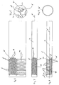
- FIG. 1 to 4 Based on Fig. 1 to 4 the basic structure of an endoscopic instrument or a tubular shaft for such an instrument according to a first preferred embodiment of the invention will be explained. It should be noted that in Fig. 1 and 2 only the tubular shaft of the Instrument is shown schematically, in Fig. 1 only some of the plurality of pipe sections 4 of the tubular shaft 2 are shown, from which the flexible part of the tubular shaft 2 is formed. It is to be understood that here further tube sections of appropriate design can be formed in the tubular shaft 2. Accordingly, in Fig. 2 only a single connection between two pipe sections 4 to illustrate the configuration of this connection shown.
- the flexible or articulated part of the tubular shaft 2 is formed from a plurality of tubular sections 4 arranged one behind the other in the axial direction X.
- the pipe sections 4 are each in positive engagement with each other at two diametrically opposite in the peripheral wall formed joints 6.
- This articulated connection is similar in structure, as for example DE 195 34 112 A1 or off DE 195 35 179 A1 is known.
- the articulated joints 6 each have a circular pin 8 on a pipe section and a corresponding circular recess 10 on an adjacent pipe section 4.
- the pin 8 engages fittingly and positively in the recess 10, so that it can rotate in the recess 10.
- the parting line 12 between the two pipe sections 4 is formed so that on one side of the circumference, starting from the two diametrically opposed articulated joints 6 wider cutouts 14 are formed. Ie. In this area, the adjacent pipe sections 4 are further spaced from each other.
- the cutouts 14 are shaped such that they expand starting from the two articulated connections 6, so that the greatest width in the longitudinal direction X is located substantially at an angular position offset by 90 ° relative to the two articulated connections 6 on the circumference of the tubular shaft 2.
- the cutouts 14 allow each two adjacent pipe sections 4 about the hinge joints 6 to the peripheral side, on which the cutouts 14 are formed, can be pivoted.
- the individual pipe sections 4 pivot in each case articulated to each other about a pivot axis which extends through the centers of the pins 8 transversely or normal to the longitudinal axis X.
- the tubular shaft curves around an external fictitious point with the radius r, wherein the radius r decreases with increasing curvature.
- the maximum curvature with the maximum pivoting angle Y of each tubular shaft 2 is achieved when, in the region of the cutouts 14, the mutually opposite end edges of the adjacent pipe sections 4 come to rest against each other.
- the parting line 12 widens on the diametrically opposite side of the cutout 14.
- the articulated connections 6 are completely formed in the wall 16 of the pipe sections 4 and der Rohrschaftes 2.
- the available cross-section is optimally utilized.
- the outer diameter of the instrument is not increased by the joints and at the same time the free lumen in the interior of the tubular shaft 2 is not reduced by the joints 6.
- the pin 8 and the recesses 10 are curved with the course of the peripheral wall 16. This causes the pins 8 and the recesses 10 on its radially inner side in the extension direction of the circumferential direction 16 have a smaller diameter than on the outside. Ie. the pins 8 are thus generally conical to the interior of the tubular shaft 2. In this way, a lateral displacement in the diameter direction or direction the pivot axis Y transverse or normal to the longitudinal axis X can be prevented.
- the individual pipe sections 4 are not completely separated from one another by the parting lines 12. Rather, the parting lines 12 are formed on the cutouts 14 diametrically opposite side so that each continuous connecting webs 18 are formed between the individual pipe sections 4, which connect adjacent pipe sections 4 together. Ie. the pipe sections 4 are not completely separated from each other, but are held together in addition to the articulated joints 6 by the connecting webs 18.
- the connecting webs 18 extend in a zigzag or S-shaped or meandering manner with respect to the longitudinal axis X between adjacent pipe sections 4. In this way, an elasticity or spring action of the connecting webs 18 in the direction of the longitudinal axis X is achieved.
- the connecting webs 18 when deflecting or pivoting of the flexible portion of the pipe section 2, in which the individual pipe sections 4, as described above, pivot about their pins 8, stretch.
- the pipe sections 4 move away from each other during pivoting, while they approach each other in the region of the cutout 14.
- the thereby taking place expansion of the connecting webs 18 takes place in that in the S-shaped course of the connecting webs 18, a bend in the region of the curves or radii of the connecting webs 18 takes place, wherein the straight sections or legs between these radii of the connecting webs 18 are further from each other remove.
- This elastic deformation of the connecting webs 18 generates a restoring or spring force, which is for a provision of the tubular shaft 2 in the in Fig. 1 shown stretched position, as soon as the force is released to deflect or at least facilitates this return movement.
- the stretched state of the connecting webs 18 is in the 10 and 11 to recognize, in which the tubular shaft 2 is deflected or curved.
- FIGS. 10 and 11 show a second embodiment of the invention, which differs from that of FIGS Fig. 1 to 4 explained embodiments only in the embodiment of the articulated joints 6 different. All other details and in particular the configuration of the connecting webs 18 are identical.
- the pins 8 ' are not circular and the recesses 10' are likewise not circular in shape.
- the pins 8 ' have a part-circular outer contour on the side at which they are connected via a web 21 with an adjacent pipe section 4. In the area facing away from the web 21, the pin 8 'is formed shortened or cut off.
- the recess 10 ' has a part-circular contour only in the region adjoining its opening, the bottom of the recess 10' is likewise cut off, in this region between the bottom of the recess 10 'and the end face of the pin 8' a free space 22 remains as clearly in the enlarged detail of Fig. 6 you can see.
- This clearance 22 allows the movement of the pin 8 'in the recess 10', wherein the adjacent pipe sections 4, as shown in the Fig. 1 to 4 explains, pivot against each other, what in 10 and 11 is shown.
- the pin 8 'and the recesses 10' as in Fig. 6 shown formed. However, the pivoting would be in the same way with the in Fig. 1 to 4 shown pin 8 work.
- FIGS. 5 to 8 and 10 and 11 shown second embodiment of the invention allows due to the not completely circular shaped joints in the longitudinal direction X narrower pipe sections 4, whereby overall smaller deflection radii can be achieved.
- FIGS. 5 and 7 the meandering course of the connecting webs 18 can be seen more clearly. It shows Fig. 5 a view in which the peripheral wall of the pipe section 2 is cut open and unwound.
- the deflection or curvature of the tubular shaft 2 is effected by a tension element 24, which extends in the longitudinal direction X in a groove 26 in the peripheral wall 16 of the tubular shaft 2 and pipe sections 4.
- This tension member 24 is attached to the distal end of the tubular shaft and, moreover, movable relative to the tubular shaft. In this way, when the pulling element 24 is pulled proximally, the tubular shaft is deflected in its movable region, which is formed by the tube sections 4, as in FIG 10 and 11 shown.
- Fig. 1 . 2 and 9 such as FIGS. 13 and 14 is this tension element 24 not shown, but it is understood that it is arranged there in a corresponding manner.
- the connecting webs 18 strive to be in their in the Fig. 1 . 5 to 8 such as 12 to 14technischzuste compassion shown starting position, ie the connecting webs 18 generate here a restoring force or a part of the restoring force.
- the connecting webs 18 between the individual pipe sections 4 provide with constant flexibility or mobility of the tubular shaft 2 for increased stability, which allows a greater power transmission, since they in particular in lateral, d. H. radial or circumferential direction with respect to the longitudinal axis X allow greater power transmission between the mutually movable pipe sections 4.
- Fig. 12 to 14 show a further embodiment of the invention, in which on the one hand, the connecting webs 18 are designed somewhat differently than in the embodiments described above.
- the connecting webs 18 have more turns and the turns are also in the Fig. 12 to 14 shown elongated initial position of the tubular shaft 2 slightly spaced from each other, wherein the column 20 between the individual turns or circumferentially extending legs of the connecting webs 18 at curvature similar to 10 and 11 be removed further from each other.
- the pins 8 and the associated recesses 10 are likewise configured with a circular contour, they have a hook-like shape near the web 21.
- the pivoting is the same as based on the Fig. 1 to 4 described.
- the main difference to the embodiments described above is that diametrically opposed to the connecting webs 18 in the wall 16 of the pipe sections 4 further connecting webs 28 between adjacent pipe sections 4 are formed.
- the connecting webs 28 are like the connecting webs 18 formed in the peripheral wall 16 of the tubular shaft 2 itself and have However, in the connecting webs 28, the turns are larger and in the rest position shown further spaced from each other, since the connecting webs 18 have an effect as a compression spring in the longitudinal direction X.
- the pipe sections 4 are pivoted about the joints 6, so that they are approximated in the region of the cutouts 14 to each other. Since the connecting webs 28 on the peripheral side, on which the recesses 14 have their greatest width, are arranged, the connecting webs 18 are thereby compressed, that is, their turns approximate each other. This follows by a bend in the region of the radii of curvature between the individual legs of the connecting webs 28.
- the connecting webs 28 Simultaneously with the elongation of the connecting webs 18, the connecting webs 28 thus generate a further restoring force, because of their elasticity, the pipe sections 4 in the region of the cutouts 14 to push apart again.
- the connecting webs 28, which connect the adjacent pipe sections 4 in one piece according to the arrangement of the connecting webs 18, ensure additional stability in the diameter or circumferential direction.
- a deflection or curvature of the tubular shaft 2 is provided only in one plane in one direction.
- the articulated connections 6 are all arranged in the same circumferential region in the longitudinal direction X on a line.
- the connecting webs 18 and 28 are arranged lying in a longitudinal direction on a line.
- FIG. 15 An example of such an embodiment is in Fig. 15 shown.
- the pipe sections 4 are interconnected so that the articulated joints 6, consisting of pin 8 and recess 10 between adjacent pipe sections 4 are alternately offset by 90 ° with respect to the longitudinal axis X are arranged.
- the normally mutually oriented pivot axes always alternate. That is, viewed in the direction of the longitudinal axis, a first pivot axis between a first and a second pipe section in a first direction, while the next pivot axis between the second and a third pipe section is rotated by 90 ° or directed with respect to the longitudinal axis X, and so on.
- the tubular shaft 2 with the cutouts 14, the articulated joints 6 and the connecting webs 18 and 28 is made of a tube by the joints 2 and the recesses and joints, which form the connecting webs 18 are cut into the pipe. This can be done for example by laser beam or electron beam cutting. In this way, it is very easy to introduce complex shapes in the wall 16 of the tubular shaft 2 and to design the individual pipe sections 4 in one piece and at the same time to ensure the mobility around the joints.
Landscapes
- Health & Medical Sciences (AREA)
- Life Sciences & Earth Sciences (AREA)
- Surgery (AREA)
- Biomedical Technology (AREA)
- Medical Informatics (AREA)
- Optics & Photonics (AREA)
- Pathology (AREA)
- Radiology & Medical Imaging (AREA)
- Biophysics (AREA)
- Engineering & Computer Science (AREA)
- Physics & Mathematics (AREA)
- Heart & Thoracic Surgery (AREA)
- Nuclear Medicine, Radiotherapy & Molecular Imaging (AREA)
- Molecular Biology (AREA)
- Animal Behavior & Ethology (AREA)
- General Health & Medical Sciences (AREA)
- Public Health (AREA)
- Veterinary Medicine (AREA)
- Endoscopes (AREA)
- Surgical Instruments (AREA)
Abstract
Description
Die Erfindung betrifft ein endoskopisches Instrument mit einem flexibel ausgebildeten Rohrschaft.The invention relates to an endoscopic instrument with a flexibly formed tubular shaft.
Beispielsweise aus
Im Hinblick auf diesen Stand der Technik ist es Aufgabe der Erfindung, ein endoskopisches Instrument mit einem flexibel ausgebildeten Rohrschaft zu schaffen, bei welchem der Rohrschaft eine möglichst große Flexibilität aufweist und darüber hinaus größere Kräfte übertragen werden können.In view of this prior art, it is an object of the invention to provide an endoscopic instrument with a flexible tubular shaft, in which the tubular shaft has the greatest possible flexibility and, moreover, greater forces can be transmitted.
Diese Aufgabe wird durch ein endoskopisches Instrument mit den im Anspruch 1 angegebenen Merkmalen gelöst. Bevorzugte Ausführungsformen ergeben sich aus den Unteransprüchen, der nachfolgenden Beschreibung sowie den beigefügten Figuren.This object is achieved by an endoscopic instrument having the features specified in claim 1. Preferred embodiments will become apparent from the subclaims, the following description and the accompanying figures.
Das erfindungsgemäße endoskopische Instrument weist einen flexibel ausgebildeten Rohrschaft auf, welcher aus mehreren Rohrabschnitten gebildet ist. Die Rohrabschnitte sind axial hintereinanderliegend angeordnet und jeweils gelenkig miteinander verbunden, so dass die einzelnen Rohrabschnitte gelenkig gegeneinander verschwenken können.The endoscopic instrument according to the invention has a flexibly formed tubular shaft which is formed from a plurality of tube sections. The pipe sections are arranged axially one behind the other and each articulated to each other, so that the individual pipe sections can pivot against each other articulated.
Zusätzlich zu den gelenkigen Verbindungen sind die einzelnen Rohrabschnitte jeweils über zumindest einen federnden Verbindungssteg miteinander verbunden. Der Verbindungssteg bzw. die Verbindungsstege verbinden jeweils benachbarte Rohrabschnitte in der Weise, dass der Verbindungssteg in axialer Richtung des Rohrschaftes federnd ausgebildet ist. Die Verbindungsstege sind mit den angrenzenden Rohrabschnitten vorzugsweise körperlich, insbesondere stoffschlüssig verbunden. Die Anordnung des zusätzlichen Verbindungssteges hat den Vorteil, dass gegenüber der rein gelenkigen Verbindung eine festere Verbindung der einzelnen Rohrabschnitte geschaffen wird, welche eine größere Kraftübertragung zulässt. Gleichzeitig gewährleistet die federnde Gestaltung des Verbindungssteges eine ausreichende Beweglichkeit zwischen den einzelnen Rohrabschnitten, so dass eine große Flexibilität des Rohrschaftes aufrechterhalten wird.In addition to the articulated connections, the individual pipe sections are connected to each other via at least one resilient connecting web. The connecting web or the connecting webs respectively connect adjacent pipe sections in such a way that the connecting web is resilient in the axial direction of the tubular shaft. The connecting webs are connected to the adjacent pipe sections preferably physically, in particular cohesively. The arrangement of the additional connecting web has the advantage that compared to the purely articulated connection a firmer connection of the individual pipe sections is created, which allows a greater power transmission. At the same time ensures the resilient design of the connecting web sufficient mobility between the individual pipe sections, so that a great flexibility of the tubular shaft is maintained.
Die Verbindungsstege sorgen dafür, dass neben der gelenkigen Verbindung eine feste Verbindung zwischen den einzelnen Rohrabschnitten besteht, so dass diese zusammengehalten werden. So kann der Verbindungssteg besonders bevorzugt quer zur Axialrichtung wirkende Kräfte übertragen, welche von den gelenkigen Verbindungen nicht übertragen werden können.The connecting webs ensure that in addition to the articulated connection a firm connection between the individual pipe sections, so that they are held together. Thus, the connecting web can particularly preferably transmit forces acting transversely to the axial direction, which can not be transmitted by the articulated connections.
Vorzugsweise sind die Verbindungsstege einstückig mit den angrenzenden Rohrabschnitten ausgebildet. Dies ermöglicht eine feste Verbindung aller Rohrabschnitte, ohne dass komplizierte Montagevorgänge erforderlich wären. Darüber hinaus kann die Anbindung des Verbindungssteges an die Rohrabschnitte äußerst schlank bzw. dünn gestaltet werden, so dass das freie Lumen im Inneren des Rohrschaftes möglichst groß ausgebildet werden kann.Preferably, the connecting webs are formed integrally with the adjacent pipe sections. This allows a firm connection of all pipe sections, without complicated assembly operations would be required. In addition, the connection of the connecting web to the pipe sections can be made extremely slim or thin, so that the free lumen can be formed as large as possible inside the tubular shaft.
Die Verbindungsstege sind weiter bevorzugte Teil der Umfangswandungen der Rohrabschnitte. D. h. die Verbindungsstege sind in den Umfangswandungen der Rohrabschnitte bzw. des Rohrschaftes selber ausgebildet. Diese Ausgestaltung hat den Vorteil, dass weder der Außendurchmesser des Rohrschaftes vergrößert wird, noch das freie Lumen im Inneren des Rohrschaftes durch die Verbindungsstege verkleinert wird. Die Verbindungsstege liegen aufgrund der Ausbildung in der Umfangswandung in Axialrichtung gesehen fluchtend in der Umfangswandung und kragen in radialer Richtung vorzugsweise weder nach innen noch nach außen aus der Umfangswandung aus.The connecting webs are further preferred part of the peripheral walls of the pipe sections. Ie. the connecting webs are formed in the peripheral walls of the pipe sections or the tubular shaft itself. This embodiment has the advantage that neither the outer diameter of the tubular shaft is increased, nor the free lumen is reduced in the interior of the tubular shaft through the connecting webs. The connecting webs are due to the formation in the peripheral wall in the axial direction aligned in the peripheral wall and cantilever in the radial direction preferably neither inwardly nor outwardly from the peripheral wall.
Weiter bevorzugt wirkt der zumindest eine Verbindungssteg in axialer Richtung des Rohrschaftes als Zugfeder. Ein solcher Verbindungssteg ist bevorzugt an der Seite des Rohrschaftes angeordnet, welche beim Abwinkeln des Rohrschaftes verlängert bzw. gedehnt wird. Dies bewirkt dann, dass der Verbindungssteg beim Abwinkeln des Rohrschaftes gedehnt wird, so dass aufgrund der Wirkung als Zugfeder Rückstellkräfte erzeugt werden, welche den Rohrschaft selbsttätig in seine gestreckte Lage zurückziehen bzw. die Bewegung zurück in die gestreckte Lage unterstützten. Es ist auch eine Ausgestaltung als Druckfeder möglich, dann wird der Verbindungssteg an der Umfangsseite angeordnet, zu der hin die Auslenkung des Rohrschaftes erfolgt, d. h. an der Umfangsseite, die gestaucht wird.More preferably, the at least one connecting web in the axial direction of the tubular shaft acts as a tension spring. Such a connecting web is preferably arranged on the side of the tubular shaft, which is extended or expanded when the tubular shaft is bent. This then causes the connecting web is stretched when bending the tubular shaft, so that due to the action as a tension spring restoring forces are generated, which automatically withdraw the tubular shaft in its extended position or supported the movement back into the extended position. It is also an embodiment as a compression spring possible, then the connecting web is arranged on the peripheral side, to which the deflection of the tubular shaft takes place, d. H. on the peripheral side, which is compressed.
Das Auslenken des Rohrschaftes kann in bekannter Weise durch ein Zugmittel erfolgen, welches sich an einer Umfangsseite des Rohrschaftes in axialer Richtung erstreckt. Vorzugsweise ist dieses Zugmittel in eine Nut in der Umfangswandung eingelegt.The deflection of the tubular shaft can be effected in a known manner by a traction means which extends on a peripheral side of the tubular shaft in the axial direction. Preferably, this traction means is inserted in a groove in the peripheral wall.
Besonders bevorzugt sind die Verbindungsstege zwischen den mehreren Rohrabschnitten alle im selben Umfangsbereich des Rohrschaftes gelegen. D. h. die einzelnen Verbindungsstege zwischen jeweils benachbarten Rohrabschnitten liegen bevorzugt in Axialrichtung alle auf einer Linie an derselben Winkelposition bezüglich der Längsachse des Rohrschaftes. Besonders bevorzugt handelt es sich dabei um die Umfangsseite bzw. Winkelposition, an welcher der Rohrschaft beim Abwinkeln am stärksten gedehnt wird, d. h. demjenigen Winkelbereich, an welchem sich die einzelnen Rohrabschnitte beim Abwinkeln am meisten voneinander entfernen.Particularly preferably, the connecting webs between the several pipe sections are all in the same circumferential region of the tubular shaft located. Ie. the individual connecting webs between respectively adjacent pipe sections are preferably all in the axial direction on a line at the same angular position with respect to the longitudinal axis of the tubular shaft. Particularly preferably, this is the circumferential side or angular position at which the tubular shaft is stretched the most when bending, ie the angle range at which the individual pipe sections at bending the most remove each other.
Der Rohrschaft ist vorzugsweise in einer Ebene beweglich, wobei sich die Wirkungslinien der federnden Verbindungsstege zwischen den Rohrabschnitten in dieser Ebene erstrecken. D. h., wie vorangehend beschrieben, erstrecken sich die Verbindungsstege mit ihren Wirkungslinien vorzugsweise entlang einer Linie in axialer Richtung des Rohrschaftes, wobei diese eine Linie in der Bewegungsebene gelegen ist, in welcher der Rohrschaft abgewinkelt wird.The tubular shaft is preferably movable in a plane, wherein the lines of action of the resilient connecting webs extend between the pipe sections in this plane. That is, as described above, the connecting webs preferably extend with their lines of action along a line in the axial direction of the tubular shaft, which is a line in the plane of movement in which the tubular shaft is angled.
Gemäß einer weiteren bevorzugten Ausführungsform sind jeweils zwei zueinander benachbarte Rohrabschnitte über in der Umfangswandung der Rohrabschnitte ausgebildete scharnierartige Gelenke formschlüssig miteinander in Eingriff. Diese Gelenke ermöglichen eine große Beweglichkeit der Rohrabschnitte zueinander in der Knick- bzw. Auslenkrichtung des Rohrschaftes. Durch die Ausgestaltung der Gelenke innerhalb der Umfangswandung, in der Weise, dass die Gelenke vorzugsweise in radialer Richtung weder nach außen noch nach innen von der Umfangswandung auskragen, wird dabei der Außendurchmesser des Instrumentes gering und gleichzeitig das freie Lumen im Inneren möglichst groß gehalten. Diese scharnierartigen Gelenke können beispielsweise wie aus
Der Verbindungssteg zwischen zwei benachbarten Rohrabschnitten verläuft vorzugsweise mäanderförmig bezüglich seiner Wirkungslinie.The connecting web between two adjacent pipe sections preferably runs meander-shaped with respect to its line of action.
Durch diese S-förmige bzw. mäanderförmige Gestalt wird die Federwirkung in Richtung der Wirkungslinie erreicht. Dabei wird die Federwirkung im Wesentlichen nicht durch Dehnung des Materials in Längsrichtung des Verbindungssteges, sondern in erster Linie durch elastische Biegung in der S- bzw. mäanderförmigen Gestalt des Verbindungssteges erreicht. Die einzelnen Stege bzw. Schenkel werden dabei um ihre Verbindungsbereiche auseinandergebogen. Bei Ausgestaltung als Druckfeder werden die Schenkel entsprechend zusammengebogen, so dass es zu einer Stauchung des Verbindungssteges kommt. Auf diese Weise kann eine große Längenänderung, insbesondere Längung bzw. Dehnung des Verbindungssteges in axialer Richtung des Rohrschaftes beim Auslenken des Rohrschaftes erreicht werden. Ferner wird eine große Stabilität in seitlicher Richtung, d. h. radialer Richtung gewährleistet.By this S-shaped or meandering shape, the spring action is achieved in the direction of the line of action. The spring effect is essentially not achieved by stretching the material in the longitudinal direction of the connecting web, but primarily by elastic bending in the S- or meandering shape of the connecting web. The individual webs or legs are thereby bent apart around their connection areas. When configured as a compression spring, the legs are bent together accordingly, so that there is a compression of the connecting web. In this way, a large change in length, in particular elongation or elongation of the connecting web in the axial direction of the tubular shaft when deflecting the tubular shaft can be achieved. Furthermore, a great stability in the lateral direction, i. H. ensured radial direction.
Gemäß einer weiteren möglichen Ausführungsform der Erfindung sind zwischen zwei zueinander benachbarten Rohrabschnitten jeweils zwei federnde Verbindungsstege in diametral entgegengesetzten Umfangsbereichen angeordnet, welche die Rohrabschnitte miteinander verbinden, wobei vorzugsweise einer der Verbindungsstege als Zug- und der andere als Druckfeder in Richtung der Längsachse des Rohrschaftes wirkt. Beide Verbindungsstege sind dabei vorzugsweise so angeordnet, dass die Wirkungslinien ihrer Federwirkung in der Schwenk- bzw. Knickebene des Rohrschaftes liegen. Dabei ist der als Zugfeder wirkende Verbindungssteg an der Seite des Rohrschaftes angeordnet, welcher beim Abwinkeln bzw. Auslenken am größten gedehnt wird, während der als Druckfeder wirkende Verbindungssteg an der diametral entgegengesetzten Seite des Rohrschaftes angeordnet ist, zu der der Rohrschaft hin ausgelenkt wird. Dies ist die Seite, welche beim Auslenken am stärksten gestaucht wird. So wird der als Druckfeder wirkende Verbindungssteg beim Auslenken gestaucht, während der als Zugfeder wirkende Verbindungssteg gedehnt wird. Auf diese Weise wird eine größere Rückstellkraft erzeugt, welche die Rohrabschnitte wieder in ihre gestreckte Ausgangslage zurückbewegen bzw. eine solche Rückstellbewegung unterstützen. Ferner wird durch die Anordnung von zwei Verbindungsstegen eine größere Stabilität zwischen den beiden Rohrabschnitten, insbesondere in Durchmesserrichtung erreicht, so dass insgesamt mit dem Rohrschaft eine größere Kraftübertragung möglich ist.According to a further possible embodiment of the invention, two resilient connecting webs are arranged in diametrically opposite circumferential regions between two mutually adjacent pipe sections, which connect the pipe sections together, preferably one of the connecting webs acts as a tension and the other as a compression spring in the direction of the longitudinal axis of the tubular shaft. Both connecting webs are preferably arranged so that the lines of action of their spring action lie in the pivoting or buckling plane of the tubular shaft. In this case, acting as a tension spring connecting web is arranged on the side of the tubular shaft, which is stretched during bending or deflection the largest, while acting as a compression spring connecting web is disposed on the diametrically opposite side of the tubular shaft, to which the tubular shaft is deflected out. This is the side that is most compressed when deflecting. Thus, the acting as a compression spring connecting web is compressed during deflection, while the acting as a tension spring connecting web is stretched. In this way, a greater restoring force is generated, which returns the pipe sections in their stretched Move back starting position or support such a return movement. Furthermore, a greater stability between the two pipe sections, in particular in the diameter direction is achieved by the arrangement of two connecting webs, so that overall with the tubular shaft, a greater power transmission is possible.
Gemäß einer weiteren bevorzugten Ausführungsform weisen die Verbindungsstege zwischen unterschiedlichen Paaren von zueinander benachbarten Rohrabschnitten unterschiedliche Federeigenschaften auf. Über die Länge des Rohrschaftes gesehen sind mehrere bzw. eine Vielzahl von Rohrabschnitten hintereinanderliegend angeordnet, welche jeweils über zumindest einen Verbindungssteg miteinander verbunden sind. Gemäß dieser bevorzugten Ausführungsform sind diese Verbindungsstege nicht alle gleich, insbesondere nicht mit den gleichen Federeigenschaften ausgebildet. So kann ein Rohrschaft geschaffen werden, welcher über seine Länge unterschiedliche Steifigkeiten bzw. flexible Eigenschaften aufweist. Es können Bereiche vorgesehen werden, welche steifer ausgebildet sind als andere Bereiche. Ferner können so Bereiche geschaffen werden, in welchen beim Auslenken bzw. Abwinkeln des Rohrschaftes dieser stärker geknickt wird als in anderen Bereichen. So kann das Instrument von seinen flexiblen Eigenschaften her optimal an den gewünschten Einsatzzweck angepasst werden.According to a further preferred embodiment, the connecting webs between different pairs of mutually adjacent pipe sections have different spring properties. Seen over the length of the tubular shaft, a plurality or a plurality of pipe sections are arranged one behind the other, which are each connected to one another via at least one connecting web. According to this preferred embodiment, these connecting webs are not all the same, in particular not formed with the same spring properties. Thus, a tubular shaft can be created, which has different stiffness or flexible properties over its length. Areas may be provided which are stiffer than other areas. Furthermore, it is thus possible to create regions in which, when deflecting or bending the tubular shaft, it is bent more sharply than in other areas. This allows the instrument to be optimally adapted to the desired application due to its flexible properties.
Besonders bevorzugt sind die Verbindungsstege in den Umfangswandungen durch Einbringen von Trennfugen in die Umfangswandungen der Rohrabschnitte ausgebildet. So ist es möglich, die Verbindungsstege einstückig mit den Rohrabschnitten auszubilden, indem in die Wandung des Rohres, aus dem die Rohrabschnitte gebildet sind, entsprechende Einschnitte eingebracht werden, welche die Verbindungsstege ausformen. So werden die Verbindungsstege direkt in der Umfangswandung ausgebildet. Je nach Form der Einschnitte ist dabei eine sehr flexible Formgebung für die Verbindungsstege möglich. Auch die Gelenke zwischen den einzelnen Rohrabschnitten und die zwischen den Rohrabschnitten gelegenen Trennfugen werden vorzugsweise in ein durchgehendes Rohr geschnitten. So können alle Rohrabschnitte, die diese verbindenden Gelenke sowie Verbindungsstege direkt in ein einstückiges durchgehendes Rohr eingeschnitten werden. Dieses Rohr kann sich ohne Einschnitte ferner einstückig weiter proximalwärts erstrecken, so dass ein durchgehender Rohrschaft des Instrumentes geschaffen werden kann, welcher am distalen Ende flexibel bzw. auslenkbar ist und am proximalen Ende starr ausgebildet ist. Die Trennfugen bzw. Einschnitte können beispielsweise durch Laserstrahl- oder Elektrodenstrahlschneiden ausgebildet werden.Particularly preferably, the connecting webs are formed in the peripheral walls by introducing parting lines in the peripheral walls of the pipe sections. Thus, it is possible to form the connecting webs integrally with the pipe sections by corresponding incisions are introduced into the wall of the tube from which the pipe sections are formed, which form the connecting webs. Thus, the connecting webs are formed directly in the peripheral wall. Depending on the shape of the incisions, a very flexible shaping of the connecting webs is possible. Also the joints between the individual pipe sections and the joints between the pipe sections are preferably cut into a continuous pipe. So all pipe sections, these connecting joints and connecting webs can be cut directly into a one-piece continuous pipe. This tube may further extend integrally further without proximally proximally, so that a continuous tubular shaft of the instrument can be created, which is flexible or deflectable at the distal end and is rigid at the proximal end. The parting lines or cuts can be formed for example by laser beam or electron beam cutting.
Weiter bevorzugt sind zwischen den einzelnen Rohrabschnitten Trennfugen ausgebildet, welche jeweils in einem, vorzugsweise alle Trennfugen im selben, Umfangsbereich des Rohrschaftes eine in Richtung der Längsachse des Rohrschaftes größere Breite aufweisen als in den anderen Umfangsbereichen und insbesondere als in einem diametral entgegengesetzten Umfangsbereich. D. h. in dem Bereich, zu welchem der Rohrschaft hin ausgelenkt bzw. abgewinkelt werden soll, werden die Trennfugen breiter ausgebildet, so dass dort die einzelnen Rohrabschnitte in gestrecktem Zustand des Rohrschaftes weiter voneinander entfernt sind. Im abgewinkelten Zustand des Rohrschaftes werden in diesem Bereich die einzelnen Rohrsegmente aufeinander zu bewegt, so dass die Trennfugen im vollständig abgewinkelten Zustand in diesem Bereich vorzugsweise nahezu vollständig geschlossen sind, d. h. die einzelnen Rohrabschnitte aneinander anliegen. Auf der entgegengesetzten Umfangsseite bewegen sich gleichzeitig die Rohrabschnitte auseinander, so dass beim Abwinkeln hier die Trennfugen erweitert werden. D. h. in diesem Umfangsbereich des Rohrschaftes, in welchem die größte Streckung auftritt, entfernen sich die einzelnen Rohrabschnitte voneinander, welche in der gestreckten Lage nahezu vollständig aneinander anliegen. In diesem Bereich ist vorzugsweise auch der elastische bzw. federnde Verbindungssteg angeordnet, welcher beim Abwinkeln gestreckt wird.Further preferably, separating joints are formed between the individual pipe sections, which have a greater width in the direction of the longitudinal axis of the tubular shaft in one, preferably all joints in the same circumferential region of the tubular shaft than in the other peripheral regions and in particular as in a diametrically opposite circumferential region. Ie. In the region to which the tubular shaft is to be deflected or bent, the joints are made wider, so that there the individual pipe sections are further apart in the stretched state of the tubular shaft. In the angled state of the tubular shaft, the individual tube segments are moved towards each other in this area, so that the joints in the fully angled state in this area are preferably almost completely closed, that is, the individual pipe sections abut each other. At the same time, the pipe sections move apart on the opposite circumferential side so that the joints are widened when bent. Ie. In this peripheral region of the tubular shaft, in which the greatest stretch occurs, the individual tube sections move away from each other, which abut in the extended position almost completely against each other. In this area is preferably also the elastic or arranged resilient connecting web, which is stretched when bending.
Die sich erweiternden Trennfugen sind vorzugsweise so ausgebildet, dass die Trennfugen sich, ausgehend von den zwei diametral entgegengesetzt angeordneten Gelenkpunkten, zu dem Umfangsbereich, welcher genau zwischen diesen Gelenkpunkten liegt, erweitern. An der entgegengesetzten Umfangsseite ist die Trennfuge nur sehr schmal ausgebildet, so dass hier die Rohrabschnitte im gestreckten Zustand des Rohrschaftes im Wesentlichen aneinander anliegen.The widening parting lines are preferably formed so that the parting lines, starting from the two diametrically opposite hinge points, to the peripheral region, which lies exactly between these hinge points widen. On the opposite circumferential side of the parting line is formed only very narrow, so that in this case the pipe sections in the extended state of the tubular shaft substantially abut each other.
Nachfolgend wird die Erfindung beispielhaft anhand der beigefügten Figuren beschrieben. In diesen zeigt:
- Fig. 1
- Eine Seitenansicht eines Rohrschaftes für ein endoskopisches Instrument gemäß einer ersten Ausführungsform der Erfindung,
- Fig. 2
- eine vereinfachte Seitenansicht des Rohrschaftes gemäß
Fig. 1 , - Fig. 3
- eine vergrößerte Detailansicht des Ausschnitts III in
Fig. 2 , - Fig. 4
- eine Schnittansicht entlang Linie IV-IV in
Fig. 3 , - Fig. 5
- eine abgewinkelte Darstellung eines Rohrschaftes für ein endoskopisches Instrument gemäß einer zweiten Ausführungsform der Erfindung,
- Fig. 6
- eine vergrößerte Darstellung der gelenkigen Verbindung zweier Rohrabschnitte gemäß der Ausführungsform in
Fig. 5 , - Fig. 7
- eine Seitenansicht des Rohrschaftes gemäß
Fig. 5 von der Seite der Verbindungsstege her gesehen, - Fig. 8
- eine um 90° gedrehte Seitenansicht des Rohrschaftes gemäß
Fig. 7 , - Fig. 9
- eine Schnittansicht des Rohrschaftes gemäß
Fig. 8 , - Fig. 10
- eine Ansicht des Rohrschaftes gemäß
Fig. 5 bis 9 im abgewinkelten Zustand, - Fig. 11
- eine Schnittansicht des abgewinkelten Rohrschaftes gemäß
Fig. 10 , - Fig. 12
- eine Seitenansicht eines Rohrschaftes für ein endoskopisches Instrument gemäß einer dritten Ausführungsform der Erfindung,
- Fig. 13
- eine um 90° gedrehte Seitenansicht des Rohrschaftes gemäß
Fig. 12 , - Fig. 14
- eine gegenüber
Fig. 13 nochmals um 90° gedrehte Seitenansicht des Rohrschaftes gemäß derFig. 12 undund 13 - Fig. 15
- einen Rohrschaft gemäß einer weiteren Ausführungsform der Erfindung.
- Fig. 1
- A side view of a tubular shaft for an endoscopic instrument according to a first embodiment of the invention,
- Fig. 2
- a simplified side view of the tubular shaft according to
Fig. 1 . - Fig. 3
- an enlarged detail view of section III in
Fig. 2 . - Fig. 4
- a sectional view taken along line IV-IV in
Fig. 3 . - Fig. 5
- an angled representation of a tubular shaft for an endoscopic instrument according to a second embodiment of the invention,
- Fig. 6
- an enlarged view of the articulated connection of two pipe sections according to the embodiment in
Fig. 5 . - Fig. 7
- a side view of the tubular shaft according to
Fig. 5 seen from the side of the connecting webs, - Fig. 8
- a rotated by 90 ° side view of the tubular shaft according to
Fig. 7 . - Fig. 9
- a sectional view of the tubular shaft according to
Fig. 8 . - Fig. 10
- a view of the tubular shaft according to
Fig. 5 to 9 in the angled state, - Fig. 11
- a sectional view of the angled tubular shaft according to
Fig. 10 . - Fig. 12
- a side view of a tubular shaft for an endoscopic instrument according to a third embodiment of the invention,
- Fig. 13
- a rotated by 90 ° side view of the tubular shaft according to
Fig. 12 . - Fig. 14
- one opposite
Fig. 13 rotated again by 90 ° side view of the tubular shaft according to theFIGS. 12 and 13 and - Fig. 15
- a tubular shaft according to another embodiment of the invention.
Anhand der
Der flexible bzw. gelenkige Teil des Rohrschaftes 2 ist aus einer Mehrzahl in axialer Richtung X hintereinanderliegenden Rohrabschnitten 4 gebildet. Die Rohrabschnitte 4 sind jeweils an zwei diametral entgegengesetzt in der Umfangswandung ausgebildeten Gelenken 6 formschlüssig miteinander in Eingriff. Diese gelenkige Verbindung ist ähnlich aufgebaut, wie es beispielsweise aus
Wie in
Wie in der Schnittansicht in
Erfindungsgemäß sind die einzelnen Rohrabschnitte 4 durch die Trennfugen 12 nicht vollständig voneinander getrennt. Vielmehr sind die Trennfugen 12 an der den Ausschnitte 14 diametral entgegengesetzten Seite so geformt, dass jeweils durchgehende Verbindungsstege 18 zwischen den einzelnen Rohrabschnitten 4 ausgebildet sind, welche benachbarte Rohrabschnitte 4 miteinander verbinden. D. h. die Rohrabschnitte 4 sind nicht vollständig voneinander getrennt, sondern werden zusätzlich zu den Gelenkverbindungen 6 durch die Verbindungsstege 18 zusammengehalten. Die Verbindungsstege 18 erstrecken sich zickzackförmig bzw. S- bzw. mäanderförmig bezüglich der Längsachse X zwischen angrenzenden Rohrabschnitten 4. Auf diese Weise wird eine Elastizität bzw. Federwirkung der Verbindungsstege 18 in Richtung der Längsachse X erreicht.According to the invention, the
So können sich die Verbindungsstege 18 beim Auslenken bzw. Verschwenken des flexiblen Abschnittes des Rohrabschnittes 2, bei welchem sich die einzelnen Rohrabschnitte 4, wie oben beschrieben, um ihre Zapfen 8 verschwenken, dehnen. In dem Bereich zwischen den Rohrabschnitten 4, in dem die Verbindungsstege 18 angeordnet sind, entfernen sich die Rohrabschnitte 4 beim Verschwenken voneinander, während sie im Bereich des Ausschnittes 14 sich annähern. Die dabei erfolgende Dehnung der Verbindungsstege 18 erfolgt dadurch, dass in dem S-förmigen Verlauf der Verbindungsstege 18 eine Biegung im Bereich der Kurven bzw. Radien der Verbindungsstege 18 erfolgt, wobei die geraden Abschnitte bzw. Schenkel zwischen diesen Radien der Verbindungsstege 18 sich weiter voneinander entfernen. Diese elastische Verformung der Verbindungsstege 18 erzeugt eine Rückstell- bzw. Federkraft, welche für eine Rückstellung des Rohrschaftes 2 in die in
In den
Die in den
In den
Die Auslenkung bzw. Krümmung des Rohrschaftes 2 erfolgt durch ein Zugelement 24, welches sich in Längsrichtung X in einer Nut 26 in der Umfangswandung 16 des Rohrschaftes 2 und Rohrabschnitte 4 erstreckt. Dieses Zugelement 24 ist am distalen Ende des Rohrschaftes befestigt und im Übrigen relativ zu dem Rohrschaft beweglich. Wenn das Zugelement 24 proximalwärts gezogen wird, wird auf diese Weise der Rohrschaft in seinem beweglichen Bereich, welcher von den Rohrabschnitten 4 gebildet wird, ausgelenkt, wie in
Die Verbindungsstege 18 zwischen den einzelnen Rohrabschnitten 4 sorgen bei gleichbleibender Flexibilität bzw. Beweglichkeit des Rohrschaftes 2 für eine erhöhte Stabilität, welche eine größere Kraftübertragung zulässt, da sie insbesondere in seitlicher, d. h. radialer bzw. Umfangsrichtung bezüglich der Längsachse X größere Kraftübertragung zwischen den zueinander beweglichen Rohrabschnitten 4 ermöglichen.The connecting
Die Verbindungsstege 28 sind wie die Verbindungsstege 18 in der Umfangswandung 16 des Rohrschaftes 2 selber ausgebildet und haben ebenfalls einen S- bzw. mäanderförmigen Verlauf bezüglich der Längsachse X. Allerdings sind bei den Verbindungsstegen 28 die Windungen größer und in der gezeigten Ruhelage weiter voneinander beabstandet, da die Verbindungsstege 18 eine Wirkung als Druckfeder in Längsrichtung X aufweisen. Beim Verschwenken, ähnlich zu
In den gezeigten Beispielen ist eine Auslenkung bzw. Krümmung des Rohrschaftes 2 lediglich in einer Ebene in einer Richtung vorgesehen. Aus diesem Grunde sind in den gezeigten Beispielen die Gelenkverbindungen 6 alle im selben Umfangsbereich in Längsrichtung X auf einer Linie liegend angeordnet. Entsprechend sind auch die Verbindungsstege 18 bzw. 28 in Längsrichtung auf einer Linie liegend angeordnet. Es ist jedoch auch denkbar, eine Auslenkung in mehrere Richtungen zuzulassen, wobei dann einzelne Gelenkverbindungen 6 und damit entsprechend die Ausschnitte 14 sowie die Verbindungsstege 18 bzw. 28 in Umfangsrichtung versetzt, angeordnet werden können.In the examples shown, a deflection or curvature of the
Ein Beispiel für eine solche Ausführungsform ist in
Ferner ist es auch möglich, eine weitere Ausnehmung 14 diametral entgegengesetzt im Bereich der Verbindungsstege 18 anzuordnen, so dass ein Verschwenken auch in die entgegengesetzte Richtung möglich ist. Dann würde der Verbindungssteg 18 entsprechend dem Verbindungssteg 28 als Druckfeder wirken.Further, it is also possible to arrange a
Auch sind in den gezeigten Beispielen über die Länge des Rohrschaftes 2 sämtliche Rohrabschnitte 4 und insbesondere sämtliche Verbindungsstege 18 bzw. 28 identisch ausgebildet. Es ist jedoch denkbar, einzelne Verbindungsstege 18 bzw. 28 über die Länge des Rohrschaftes 2 unterschiedlich auszubilden, um unterschiedliche Steifigkeiten, Federkräfte und/oder Gelenkeigenschaften zwischen einzelnen Rohrabschnitten 4 bereitzustellen. So kann das Instrument durch Gestaltung seines Rohrschaftes 2 an den gewünschten Einsatzzweck optimal angepasst werden. Auch ist zu verstehen, dass die Gelenkverbindungen 6 auch auf andere Weise, insbesondere anders geformt, ausgestaltet werden können.Also, in the examples shown over the length of the
Der Rohrschaft 2 mit den Ausschnitten 14, den Gelenkverbindungen 6 und den Verbindungsstegen 18 bzw. 28 wird aus einem Rohr gefertigt, indem die Trennfugen 12 sowie die Ausnehmungen und Fugen, welche die Verbindungsstege 18 bilden, in das Rohr eingeschnitten werden. Dies kann beispielsweise durch Laserstrahl- bzw. Elektronenstrahlschneiden erfolgen. Auf diese Weise ist es sehr einfach möglich, komplexe Formgebungen in die Wandung 16 des Rohrschaftes 2 einzubringen und die einzelnen Rohrabschnitte 4 einstückig auszugestalten und gleichzeitig die Beweglichkeit um die Gelenkverbindungen zu gewährleisten.The
- 22
- Rohrschafttubular shaft
- 44
- Rohrabschnittepipe sections
- 66
- Gelenkverbindungarticulation
- 8, 8'8, 8 '
- Zapfenspigot
- 10, 10'10, 10 '
- Ausnehmungrecess
- 1212
- Trennfugeparting line
- 1414
- Ausschnittecutouts
- 1616
- Wandungwall
- 1818
- Verbindungsstegeconnecting webs
- 2020
- Spaltgap
- 2121
- StegeStege
- 2222
- Freiraumfree space
- 2424
- Zugelementtension element
- 2626
- Nutgroove
- 2828
- Verbindungsstegeconnecting webs
- XX
- Längsachselongitudinal axis
- YY
- Schwenkachseswivel axis
- rr
- Schwenkwinkelswivel angle
- rr
- Schwenkradiusswing radius
Claims (12)
dadurch gekennzeichnet, dass
jeweils zwei zueinander benachbarte Rohrabschnitte (4) zusätzlich zu der gelenkigen Verbindung (6) über zumindest einen in axialer Richtung (X) des Rohrschaftes (2) federnden Verbindungssteg (18) miteinander verbunden sind.An endoscopic instrument having a flexibly formed tubular shaft (2), in which the tubular shaft (2) is formed from a plurality of tubular sections (4) connected to one another in an articulated manner,
characterized in that
in each case two mutually adjacent pipe sections (4) in addition to the articulated connection (6) via at least one in the axial direction (X) of the tubular shaft (2) resilient connecting web (18) are interconnected.
Priority Applications (4)
| Application Number | Priority Date | Filing Date | Title |
|---|---|---|---|
| EP07007041A EP1977677B1 (en) | 2007-04-04 | 2007-04-04 | Endoscopic instrument |
| DE502007001349T DE502007001349D1 (en) | 2007-04-04 | 2007-04-04 | Endoscopic instrument |
| AT07007041T ATE439798T1 (en) | 2007-04-04 | 2007-04-04 | ENDOSCOPIC INSTRUMENT |
| US12/061,688 US20080249364A1 (en) | 2007-04-04 | 2008-04-03 | Endoscopic instrument |
Applications Claiming Priority (1)
| Application Number | Priority Date | Filing Date | Title |
|---|---|---|---|
| EP07007041A EP1977677B1 (en) | 2007-04-04 | 2007-04-04 | Endoscopic instrument |
Publications (2)
| Publication Number | Publication Date |
|---|---|
| EP1977677A1 true EP1977677A1 (en) | 2008-10-08 |
| EP1977677B1 EP1977677B1 (en) | 2009-08-19 |
Family
ID=38024551
Family Applications (1)
| Application Number | Title | Priority Date | Filing Date |
|---|---|---|---|
| EP07007041A Active EP1977677B1 (en) | 2007-04-04 | 2007-04-04 | Endoscopic instrument |
Country Status (4)
| Country | Link |
|---|---|
| US (1) | US20080249364A1 (en) |
| EP (1) | EP1977677B1 (en) |
| AT (1) | ATE439798T1 (en) |
| DE (1) | DE502007001349D1 (en) |
Cited By (9)
| Publication number | Priority date | Publication date | Assignee | Title |
|---|---|---|---|---|
| WO2010030764A3 (en) * | 2008-09-12 | 2010-05-27 | Boston Scientific Scimed, Inc. | Flexible guide conduit |
| WO2010102002A1 (en) * | 2009-03-05 | 2010-09-10 | Hansen Medical, Inc. | Lockable support assembly |
| DE102010034345A1 (en) * | 2010-08-14 | 2012-02-16 | Richard Wolf Gmbh | Endoscopic instrument comprises handle and shaft which is provided with bent section, where tubular support body is arranged in shaft, and tubular support body is divided in segments |
| WO2013128860A1 (en) * | 2012-02-28 | 2013-09-06 | Terumo Kabushiki Kaisha | Flexible tube for medical instrument and medical instrument |
| US9198561B2 (en) | 2011-01-31 | 2015-12-01 | Boston Scientific Scimed, Inc. | Articulation section with locking |
| US10357320B2 (en) | 2014-08-27 | 2019-07-23 | Distalmotion Sa | Surgical system for microsurgical techniques |
| US10363055B2 (en) | 2015-04-09 | 2019-07-30 | Distalmotion Sa | Articulated hand-held instrument |
| US10413374B2 (en) | 2018-02-07 | 2019-09-17 | Distalmotion Sa | Surgical robot systems comprising robotic telemanipulators and integrated laparoscopy |
| US10874290B2 (en) | 2015-02-26 | 2020-12-29 | Stryker Corporation | Surgical instrument with articulation region |
Families Citing this family (43)
| Publication number | Priority date | Publication date | Assignee | Title |
|---|---|---|---|---|
| US8007506B2 (en) | 2006-06-30 | 2011-08-30 | Atheromed, Inc. | Atherectomy devices and methods |
| US8628549B2 (en) | 2006-06-30 | 2014-01-14 | Atheromed, Inc. | Atherectomy devices, systems, and methods |
| US20080045986A1 (en) | 2006-06-30 | 2008-02-21 | Atheromed, Inc. | Atherectomy devices and methods |
| US20090018566A1 (en) | 2006-06-30 | 2009-01-15 | Artheromed, Inc. | Atherectomy devices, systems, and methods |
| EP2037822A4 (en) | 2006-06-30 | 2015-10-07 | Atheromed Inc | Atherectomy devices and methods |
| US9314263B2 (en) | 2006-06-30 | 2016-04-19 | Atheromed, Inc. | Atherectomy devices, systems, and methods |
| US8361094B2 (en) | 2006-06-30 | 2013-01-29 | Atheromed, Inc. | Atherectomy devices and methods |
| US20080004645A1 (en) | 2006-06-30 | 2008-01-03 | Atheromed, Inc. | Atherectomy devices and methods |
| US9492192B2 (en) | 2006-06-30 | 2016-11-15 | Atheromed, Inc. | Atherectomy devices, systems, and methods |
| US8236016B2 (en) * | 2007-10-22 | 2012-08-07 | Atheromed, Inc. | Atherectomy devices and methods |
| US8070762B2 (en) * | 2007-10-22 | 2011-12-06 | Atheromed Inc. | Atherectomy devices and methods |
| US20110040308A1 (en) * | 2008-06-13 | 2011-02-17 | Ramiro Cabrera | Endoscopic Stitching Devices |
| US8628545B2 (en) * | 2008-06-13 | 2014-01-14 | Covidien Lp | Endoscopic stitching devices |
| US7918376B1 (en) | 2009-03-09 | 2011-04-05 | Cardica, Inc. | Articulated surgical instrument |
| DE102009017175B4 (en) * | 2009-04-09 | 2011-05-05 | Richard Wolf Gmbh | Method for producing a bendable tube |
| US20100270354A1 (en) * | 2009-04-22 | 2010-10-28 | Ofir Rimer | Ergonomic rotary tacker |
| US9289208B1 (en) | 2009-05-05 | 2016-03-22 | Cardica, Inc. | Articulation insert for surgical instrument |
| US8096457B1 (en) | 2009-05-05 | 2012-01-17 | Cardica, Inc. | Articulation mechanisms for surgical instrument |
| US10092359B2 (en) | 2010-10-11 | 2018-10-09 | Ecole Polytechnique Federale De Lausanne | Mechanical manipulator for surgical instruments |
| US9038880B1 (en) | 2011-04-25 | 2015-05-26 | Cardica, Inc. | Articulated surgical instrument |
| US9474527B1 (en) | 2011-04-26 | 2016-10-25 | Bryan D. Knodel | Surgical instrument with discrete articulation |
| US9566048B1 (en) | 2011-04-26 | 2017-02-14 | Cardica, Inc. | Surgical instrument with discrete cammed articulation |
| WO2013014621A2 (en) | 2011-07-27 | 2013-01-31 | Ecole Polytechnique Federale De Lausanne (Epfl) | Mechanical teleoperated device for remote manipulation |
| JP2014533147A (en) | 2011-10-13 | 2014-12-11 | アセローメド, インコーポレイテッド | Atelectomy device, system, and method |
| US9585546B2 (en) * | 2011-11-21 | 2017-03-07 | Cook Medical Technologies Llc | Endoscope stabilization system |
| US8419720B1 (en) * | 2012-02-07 | 2013-04-16 | National Advanced Endoscopy Devices, Incorporated | Flexible laparoscopic device |
| WO2014015156A2 (en) * | 2012-07-20 | 2014-01-23 | Boston Scientific Scimed, Inc. | Elongate medical device with articulating portion |
| US10265129B2 (en) | 2014-02-03 | 2019-04-23 | Distalmotion Sa | Mechanical teleoperated device comprising an interchangeable distal instrument |
| EP3009104B1 (en) * | 2014-10-14 | 2019-11-20 | St. Jude Medical, Cardiology Division, Inc. | Flexible catheter and methods of forming same |
| EP3232977B1 (en) | 2014-12-19 | 2020-01-29 | DistalMotion SA | Docking system for mechanical telemanipulator |
| US10548680B2 (en) | 2014-12-19 | 2020-02-04 | Distalmotion Sa | Articulated handle for mechanical telemanipulator |
| EP3232973B1 (en) | 2014-12-19 | 2020-04-01 | DistalMotion SA | Sterile interface for articulated surgical instruments |
| EP4342412A3 (en) | 2014-12-19 | 2024-06-05 | DistalMotion SA | Reusable surgical instrument for minimally invasive procedures |
| ES2968221T3 (en) | 2014-12-19 | 2024-05-08 | Distalmotion Sa | Surgical instrument with articulated end effector |
| CN105759418B (en) * | 2014-12-19 | 2019-06-28 | 深圳市锐丽视科技有限公司 | Flexible number endoscope |
| US10568709B2 (en) | 2015-04-09 | 2020-02-25 | Distalmotion Sa | Mechanical teleoperated device for remote manipulation |
| WO2017037532A1 (en) | 2015-08-28 | 2017-03-09 | Distalmotion Sa | Surgical instrument with increased actuation force |
| US11058503B2 (en) | 2017-05-11 | 2021-07-13 | Distalmotion Sa | Translational instrument interface for surgical robot and surgical robot systems comprising the same |
| BR112020021682A2 (en) * | 2018-04-25 | 2022-06-07 | Innomed Five L L C | Medical device and method for improving implantation of a fertilized egg during pregnancy |
| US11197665B2 (en) | 2018-08-06 | 2021-12-14 | Covidien Lp | Needle reload device for use with endostitch device |
| US11304723B1 (en) | 2020-12-17 | 2022-04-19 | Avantec Vascular Corporation | Atherectomy devices that are self-driving with controlled deflection |
| KR102559600B1 (en) * | 2021-04-06 | 2023-07-25 | 주식회사 로엔서지컬 | Asymmetric rolling contact joint of sugical instrument |
| US11844585B1 (en) | 2023-02-10 | 2023-12-19 | Distalmotion Sa | Surgical robotics systems and devices having a sterile restart, and methods thereof |
Citations (4)
| Publication number | Priority date | Publication date | Assignee | Title |
|---|---|---|---|---|
| EP0535847A1 (en) * | 1991-10-04 | 1993-04-07 | Kabushiki Kaisha Machida Seisakusho | Endoscope |
| DE19534112A1 (en) | 1995-09-14 | 1997-03-20 | Wolf Gmbh Richard | Endoscopic instrument with steerable distal end |
| DE19928272A1 (en) * | 1999-06-21 | 2001-01-04 | Ep Flex Feinwerktechnik Gmbh | Endoscope tube flexible part has spring stabilizing zone and interposed ring zones as integral tube piece slotted out lengthways and here joined to stabilizing zone. |
| US6364828B1 (en) | 2000-01-06 | 2002-04-02 | Hubert K. Yeung | Elongated flexible inspection neck |
Family Cites Families (3)
| Publication number | Priority date | Publication date | Assignee | Title |
|---|---|---|---|---|
| JP2938486B2 (en) * | 1989-12-28 | 1999-08-23 | 株式会社町田製作所 | Curved tube and manufacturing method thereof |
| DE19535179A1 (en) * | 1995-09-22 | 1997-03-27 | Wolf Gmbh Richard | Angled pipe and process for its manufacture |
| US5749828A (en) * | 1995-12-22 | 1998-05-12 | Hewlett-Packard Company | Bending neck for use with invasive medical devices |
-
2007
- 2007-04-04 DE DE502007001349T patent/DE502007001349D1/en active Active
- 2007-04-04 EP EP07007041A patent/EP1977677B1/en active Active
- 2007-04-04 AT AT07007041T patent/ATE439798T1/en active
-
2008
- 2008-04-03 US US12/061,688 patent/US20080249364A1/en not_active Abandoned
Patent Citations (4)
| Publication number | Priority date | Publication date | Assignee | Title |
|---|---|---|---|---|
| EP0535847A1 (en) * | 1991-10-04 | 1993-04-07 | Kabushiki Kaisha Machida Seisakusho | Endoscope |
| DE19534112A1 (en) | 1995-09-14 | 1997-03-20 | Wolf Gmbh Richard | Endoscopic instrument with steerable distal end |
| DE19928272A1 (en) * | 1999-06-21 | 2001-01-04 | Ep Flex Feinwerktechnik Gmbh | Endoscope tube flexible part has spring stabilizing zone and interposed ring zones as integral tube piece slotted out lengthways and here joined to stabilizing zone. |
| US6364828B1 (en) | 2000-01-06 | 2002-04-02 | Hubert K. Yeung | Elongated flexible inspection neck |
Cited By (13)
| Publication number | Priority date | Publication date | Assignee | Title |
|---|---|---|---|---|
| WO2010030764A3 (en) * | 2008-09-12 | 2010-05-27 | Boston Scientific Scimed, Inc. | Flexible guide conduit |
| WO2010102002A1 (en) * | 2009-03-05 | 2010-09-10 | Hansen Medical, Inc. | Lockable support assembly |
| DE102010034345A1 (en) * | 2010-08-14 | 2012-02-16 | Richard Wolf Gmbh | Endoscopic instrument comprises handle and shaft which is provided with bent section, where tubular support body is arranged in shaft, and tubular support body is divided in segments |
| US9974429B2 (en) | 2011-01-31 | 2018-05-22 | Boston Scientific Scimed, Inc. | Articulation section with locking |
| US10813538B2 (en) | 2011-01-31 | 2020-10-27 | Boston Scientific Scimed, Inc. | Articulation section with locking |
| US9198561B2 (en) | 2011-01-31 | 2015-12-01 | Boston Scientific Scimed, Inc. | Articulation section with locking |
| WO2013128860A1 (en) * | 2012-02-28 | 2013-09-06 | Terumo Kabushiki Kaisha | Flexible tube for medical instrument and medical instrument |
| US9113783B2 (en) | 2012-02-28 | 2015-08-25 | Terumo Kabushiki Kaisha | Flexible tube for medical instrument and medical instrument |
| US10357320B2 (en) | 2014-08-27 | 2019-07-23 | Distalmotion Sa | Surgical system for microsurgical techniques |
| US10874290B2 (en) | 2015-02-26 | 2020-12-29 | Stryker Corporation | Surgical instrument with articulation region |
| US11660101B2 (en) | 2015-02-26 | 2023-05-30 | Stryker Corporation | Surgical instrument with articulating region |
| US10363055B2 (en) | 2015-04-09 | 2019-07-30 | Distalmotion Sa | Articulated hand-held instrument |
| US10413374B2 (en) | 2018-02-07 | 2019-09-17 | Distalmotion Sa | Surgical robot systems comprising robotic telemanipulators and integrated laparoscopy |
Also Published As
| Publication number | Publication date |
|---|---|
| EP1977677B1 (en) | 2009-08-19 |
| US20080249364A1 (en) | 2008-10-09 |
| ATE439798T1 (en) | 2009-09-15 |
| DE502007001349D1 (en) | 2009-10-01 |
Similar Documents
| Publication | Publication Date | Title |
|---|---|---|
| EP1977677B1 (en) | Endoscopic instrument | |
| EP0764423B2 (en) | Bendable pipe | |
| EP2877100B1 (en) | Shaft for medical instruments, comprising movable sections | |
| EP1604607B1 (en) | Flexible section of an insertion tube of an endoscope and method of manufacturing thereof | |
| EP3697283B1 (en) | Method for producing an endoscope insertion tube and endoscope comprising an insertion tube | |
| EP1888960B1 (en) | Anchoring element for coupling tubes | |
| DE19615940A1 (en) | Synthetic resin constant velocity joint sleeve | |
| EP2696741B1 (en) | Control apparatus | |
| EP2757299B1 (en) | Pipe clamp | |
| WO2019211456A1 (en) | Endoscope deflection using a distal folding mechanism | |
| DE202017101896U1 (en) | Cable guide | |
| DE102015110162B4 (en) | Energy guiding chain comprising a separate spring element inserted between the links, which biases the adjacent links in a preferred orientation | |
| DE102005054057B4 (en) | component | |
| EP2147646A2 (en) | Medical instrument with a flexible seal system | |
| EP1245889A1 (en) | Pipe clamp | |
| DE102009037030A1 (en) | Tubular shaped shaft for use as gripper for gripping e.g. component in laparoscopic instrument, has bendable areas attached at ends of rigid section, which exhibits bending position, and rods designed in longitudinal movable manner | |
| DE102011009371B3 (en) | Medical device with a grid structure and treatment system with such a device | |
| DE202011000848U1 (en) | control device | |
| WO2011018179A2 (en) | Shaft for a surgical instrument having flexible regions | |
| EP3173038B1 (en) | Shaft instrument | |
| DE102015204486A1 (en) | Surgical instrument | |
| EP1331421A2 (en) | Shift lever device avoiding bellow pinching | |
| DE102010034345A1 (en) | Endoscopic instrument comprises handle and shaft which is provided with bent section, where tubular support body is arranged in shaft, and tubular support body is divided in segments | |
| EP2898818B1 (en) | Endoscopic instrument | |
| DE10160922A1 (en) | Endoscope tube piece e.g. for surgical endoscope, has interlocking elements on facing tube segments surfaces for stabilizing torsional or lateral forces |
Legal Events
| Date | Code | Title | Description |
|---|---|---|---|
| PUAI | Public reference made under article 153(3) epc to a published international application that has entered the european phase |
Free format text: ORIGINAL CODE: 0009012 |
|
| 17P | Request for examination filed |
Effective date: 20080510 |
|
| AK | Designated contracting states |
Kind code of ref document: A1 Designated state(s): AT BE BG CH CY CZ DE DK EE ES FI FR GB GR HU IE IS IT LI LT LU LV MC MT NL PL PT RO SE SI SK TR |
|
| AX | Request for extension of the european patent |
Extension state: AL BA HR MK RS |
|
| GRAP | Despatch of communication of intention to grant a patent |
Free format text: ORIGINAL CODE: EPIDOSNIGR1 |
|
| GRAS | Grant fee paid |
Free format text: ORIGINAL CODE: EPIDOSNIGR3 |
|
| AKX | Designation fees paid |
Designated state(s): AT BE BG CH CY CZ DE DK EE ES FI FR GB GR HU IE IS IT LI LT LU LV MC MT NL PL PT RO SE SI SK TR |
|
| GRAA | (expected) grant |
Free format text: ORIGINAL CODE: 0009210 |
|
| AK | Designated contracting states |
Kind code of ref document: B1 Designated state(s): AT BE BG CH CY CZ DE DK EE ES FI FR GB GR HU IE IS IT LI LT LU LV MC MT NL PL PT RO SE SI SK TR |
|
| REG | Reference to a national code |
Ref country code: GB Ref legal event code: FG4D Free format text: NOT ENGLISH |
|
| REG | Reference to a national code |
Ref country code: CH Ref legal event code: NV Representative=s name: ISLER & PEDRAZZINI AG Ref country code: CH Ref legal event code: EP |
|
| REG | Reference to a national code |
Ref country code: IE Ref legal event code: FG4D |
|
| REF | Corresponds to: |
Ref document number: 502007001349 Country of ref document: DE Date of ref document: 20091001 Kind code of ref document: P |
|
| LTIE | Lt: invalidation of european patent or patent extension |
Effective date: 20090819 |
|
| PG25 | Lapsed in a contracting state [announced via postgrant information from national office to epo] |
Ref country code: FI Free format text: LAPSE BECAUSE OF FAILURE TO SUBMIT A TRANSLATION OF THE DESCRIPTION OR TO PAY THE FEE WITHIN THE PRESCRIBED TIME-LIMIT Effective date: 20090819 Ref country code: ES Free format text: LAPSE BECAUSE OF FAILURE TO SUBMIT A TRANSLATION OF THE DESCRIPTION OR TO PAY THE FEE WITHIN THE PRESCRIBED TIME-LIMIT Effective date: 20091130 Ref country code: SE Free format text: LAPSE BECAUSE OF FAILURE TO SUBMIT A TRANSLATION OF THE DESCRIPTION OR TO PAY THE FEE WITHIN THE PRESCRIBED TIME-LIMIT Effective date: 20090819 Ref country code: IS Free format text: LAPSE BECAUSE OF FAILURE TO SUBMIT A TRANSLATION OF THE DESCRIPTION OR TO PAY THE FEE WITHIN THE PRESCRIBED TIME-LIMIT Effective date: 20091219 Ref country code: LT Free format text: LAPSE BECAUSE OF FAILURE TO SUBMIT A TRANSLATION OF THE DESCRIPTION OR TO PAY THE FEE WITHIN THE PRESCRIBED TIME-LIMIT Effective date: 20090819 |
|
| PG25 | Lapsed in a contracting state [announced via postgrant information from national office to epo] |
Ref country code: SI Free format text: LAPSE BECAUSE OF FAILURE TO SUBMIT A TRANSLATION OF THE DESCRIPTION OR TO PAY THE FEE WITHIN THE PRESCRIBED TIME-LIMIT Effective date: 20090819 Ref country code: PL Free format text: LAPSE BECAUSE OF FAILURE TO SUBMIT A TRANSLATION OF THE DESCRIPTION OR TO PAY THE FEE WITHIN THE PRESCRIBED TIME-LIMIT Effective date: 20090819 Ref country code: LV Free format text: LAPSE BECAUSE OF FAILURE TO SUBMIT A TRANSLATION OF THE DESCRIPTION OR TO PAY THE FEE WITHIN THE PRESCRIBED TIME-LIMIT Effective date: 20090819 |
|
| REG | Reference to a national code |
Ref country code: IE Ref legal event code: FD4D |
|
| PG25 | Lapsed in a contracting state [announced via postgrant information from national office to epo] |
Ref country code: CY Free format text: LAPSE BECAUSE OF FAILURE TO SUBMIT A TRANSLATION OF THE DESCRIPTION OR TO PAY THE FEE WITHIN THE PRESCRIBED TIME-LIMIT Effective date: 20090819 Ref country code: BG Free format text: LAPSE BECAUSE OF FAILURE TO SUBMIT A TRANSLATION OF THE DESCRIPTION OR TO PAY THE FEE WITHIN THE PRESCRIBED TIME-LIMIT Effective date: 20091119 Ref country code: PT Free format text: LAPSE BECAUSE OF FAILURE TO SUBMIT A TRANSLATION OF THE DESCRIPTION OR TO PAY THE FEE WITHIN THE PRESCRIBED TIME-LIMIT Effective date: 20091221 |
|
| PG25 | Lapsed in a contracting state [announced via postgrant information from national office to epo] |
Ref country code: DK Free format text: LAPSE BECAUSE OF FAILURE TO SUBMIT A TRANSLATION OF THE DESCRIPTION OR TO PAY THE FEE WITHIN THE PRESCRIBED TIME-LIMIT Effective date: 20090819 Ref country code: RO Free format text: LAPSE BECAUSE OF FAILURE TO SUBMIT A TRANSLATION OF THE DESCRIPTION OR TO PAY THE FEE WITHIN THE PRESCRIBED TIME-LIMIT Effective date: 20090819 Ref country code: CZ Free format text: LAPSE BECAUSE OF FAILURE TO SUBMIT A TRANSLATION OF THE DESCRIPTION OR TO PAY THE FEE WITHIN THE PRESCRIBED TIME-LIMIT Effective date: 20090819 Ref country code: EE Free format text: LAPSE BECAUSE OF FAILURE TO SUBMIT A TRANSLATION OF THE DESCRIPTION OR TO PAY THE FEE WITHIN THE PRESCRIBED TIME-LIMIT Effective date: 20090819 Ref country code: IE Free format text: LAPSE BECAUSE OF FAILURE TO SUBMIT A TRANSLATION OF THE DESCRIPTION OR TO PAY THE FEE WITHIN THE PRESCRIBED TIME-LIMIT Effective date: 20090819 |
|
| PG25 | Lapsed in a contracting state [announced via postgrant information from national office to epo] |
Ref country code: SK Free format text: LAPSE BECAUSE OF FAILURE TO SUBMIT A TRANSLATION OF THE DESCRIPTION OR TO PAY THE FEE WITHIN THE PRESCRIBED TIME-LIMIT Effective date: 20090819 |
|
| PLBE | No opposition filed within time limit |
Free format text: ORIGINAL CODE: 0009261 |
|
| STAA | Information on the status of an ep patent application or granted ep patent |
Free format text: STATUS: NO OPPOSITION FILED WITHIN TIME LIMIT |
|
| 26N | No opposition filed |
Effective date: 20100520 |
|
| PG25 | Lapsed in a contracting state [announced via postgrant information from national office to epo] |
Ref country code: GR Free format text: LAPSE BECAUSE OF FAILURE TO SUBMIT A TRANSLATION OF THE DESCRIPTION OR TO PAY THE FEE WITHIN THE PRESCRIBED TIME-LIMIT Effective date: 20091120 |
|
| PG25 | Lapsed in a contracting state [announced via postgrant information from national office to epo] |
Ref country code: MC Free format text: LAPSE BECAUSE OF NON-PAYMENT OF DUE FEES Effective date: 20100430 |
|
| PG25 | Lapsed in a contracting state [announced via postgrant information from national office to epo] |
Ref country code: IT Free format text: LAPSE BECAUSE OF NON-PAYMENT OF DUE FEES Effective date: 20100404 |
|
| PG25 | Lapsed in a contracting state [announced via postgrant information from national office to epo] |
Ref country code: MT Free format text: LAPSE BECAUSE OF FAILURE TO SUBMIT A TRANSLATION OF THE DESCRIPTION OR TO PAY THE FEE WITHIN THE PRESCRIBED TIME-LIMIT Effective date: 20090819 |
|
| PG25 | Lapsed in a contracting state [announced via postgrant information from national office to epo] |
Ref country code: HU Free format text: LAPSE BECAUSE OF FAILURE TO SUBMIT A TRANSLATION OF THE DESCRIPTION OR TO PAY THE FEE WITHIN THE PRESCRIBED TIME-LIMIT Effective date: 20100220 |
|
| PG25 | Lapsed in a contracting state [announced via postgrant information from national office to epo] |
Ref country code: TR Free format text: LAPSE BECAUSE OF FAILURE TO SUBMIT A TRANSLATION OF THE DESCRIPTION OR TO PAY THE FEE WITHIN THE PRESCRIBED TIME-LIMIT Effective date: 20090819 |
|
| REG | Reference to a national code |
Ref country code: AT Ref legal event code: MM01 Ref document number: 439798 Country of ref document: AT Kind code of ref document: T Effective date: 20120404 |
|
| PG25 | Lapsed in a contracting state [announced via postgrant information from national office to epo] |
Ref country code: AT Free format text: LAPSE BECAUSE OF NON-PAYMENT OF DUE FEES Effective date: 20120404 |
|
| REG | Reference to a national code |
Ref country code: FR Ref legal event code: PLFP Year of fee payment: 10 |
|
| REG | Reference to a national code |
Ref country code: FR Ref legal event code: PLFP Year of fee payment: 11 |
|
| REG | Reference to a national code |
Ref country code: FR Ref legal event code: PLFP Year of fee payment: 12 |
|
| PGFP | Annual fee paid to national office [announced via postgrant information from national office to epo] |
Ref country code: LU Payment date: 20200420 Year of fee payment: 14 Ref country code: NL Payment date: 20200420 Year of fee payment: 14 Ref country code: FR Payment date: 20200421 Year of fee payment: 14 Ref country code: CH Payment date: 20200423 Year of fee payment: 14 |
|
| PGFP | Annual fee paid to national office [announced via postgrant information from national office to epo] |
Ref country code: GB Payment date: 20200423 Year of fee payment: 14 Ref country code: IT Payment date: 20200423 Year of fee payment: 14 Ref country code: BE Payment date: 20200420 Year of fee payment: 14 |
|
| REG | Reference to a national code |
Ref country code: DE Ref legal event code: R084 Ref document number: 502007001349 Country of ref document: DE |
|
| REG | Reference to a national code |
Ref country code: NL Ref legal event code: MM Effective date: 20210501 |
|
| GBPC | Gb: european patent ceased through non-payment of renewal fee |
Effective date: 20210404 |
|
| PG25 | Lapsed in a contracting state [announced via postgrant information from national office to epo] |
Ref country code: LU Free format text: LAPSE BECAUSE OF NON-PAYMENT OF DUE FEES Effective date: 20210404 |
|
| REG | Reference to a national code |
Ref country code: BE Ref legal event code: MM Effective date: 20210430 |
|
| PG25 | Lapsed in a contracting state [announced via postgrant information from national office to epo] |
Ref country code: CH Free format text: LAPSE BECAUSE OF NON-PAYMENT OF DUE FEES Effective date: 20210430 Ref country code: LI Free format text: LAPSE BECAUSE OF NON-PAYMENT OF DUE FEES Effective date: 20210430 Ref country code: GB Free format text: LAPSE BECAUSE OF NON-PAYMENT OF DUE FEES Effective date: 20210404 Ref country code: FR Free format text: LAPSE BECAUSE OF NON-PAYMENT OF DUE FEES Effective date: 20210430 |
|
| PG25 | Lapsed in a contracting state [announced via postgrant information from national office to epo] |
Ref country code: NL Free format text: LAPSE BECAUSE OF NON-PAYMENT OF DUE FEES Effective date: 20210501 |
|
| PG25 | Lapsed in a contracting state [announced via postgrant information from national office to epo] |
Ref country code: BE Free format text: LAPSE BECAUSE OF NON-PAYMENT OF DUE FEES Effective date: 20210430 |
|
| PG25 | Lapsed in a contracting state [announced via postgrant information from national office to epo] |
Ref country code: IT Free format text: LAPSE BECAUSE OF NON-PAYMENT OF DUE FEES Effective date: 20210430 |
|
| PGFP | Annual fee paid to national office [announced via postgrant information from national office to epo] |
Ref country code: DE Payment date: 20230421 Year of fee payment: 17 |