EP1976220A1 - Computer network - Google Patents
Computer network Download PDFInfo
- Publication number
- EP1976220A1 EP1976220A1 EP07251420A EP07251420A EP1976220A1 EP 1976220 A1 EP1976220 A1 EP 1976220A1 EP 07251420 A EP07251420 A EP 07251420A EP 07251420 A EP07251420 A EP 07251420A EP 1976220 A1 EP1976220 A1 EP 1976220A1
- Authority
- EP
- European Patent Office
- Prior art keywords
- group
- message
- token
- group membership
- local
- Prior art date
- Legal status (The legal status is an assumption and is not a legal conclusion. Google has not performed a legal analysis and makes no representation as to the accuracy of the status listed.)
- Ceased
Links
Images


Classifications
-
- H—ELECTRICITY
- H04—ELECTRIC COMMUNICATION TECHNIQUE
- H04L—TRANSMISSION OF DIGITAL INFORMATION, e.g. TELEGRAPHIC COMMUNICATION
- H04L63/00—Network architectures or network communication protocols for network security
- H04L63/08—Network architectures or network communication protocols for network security for authentication of entities
- H04L63/0807—Network architectures or network communication protocols for network security for authentication of entities using tickets, e.g. Kerberos
-
- H—ELECTRICITY
- H04—ELECTRIC COMMUNICATION TECHNIQUE
- H04L—TRANSMISSION OF DIGITAL INFORMATION, e.g. TELEGRAPHIC COMMUNICATION
- H04L63/00—Network architectures or network communication protocols for network security
- H04L63/10—Network architectures or network communication protocols for network security for controlling access to devices or network resources
- H04L63/102—Entity profiles
-
- H—ELECTRICITY
- H04—ELECTRIC COMMUNICATION TECHNIQUE
- H04L—TRANSMISSION OF DIGITAL INFORMATION, e.g. TELEGRAPHIC COMMUNICATION
- H04L67/00—Network arrangements or protocols for supporting network services or applications
- H04L67/01—Protocols
- H04L67/10—Protocols in which an application is distributed across nodes in the network
Definitions
- the present invention relates to a computer network and a method of operating a computer network.
- Authentication is often provided using so-called credentials - most commonly a digital certificate digitally signed by a trusted authority.
- credentials most commonly a digital certificate digitally signed by a trusted authority.
- a problem with such credentials is handling their revocation. Conventionally this is done using Certificate Revocation Lists which a person receiving a certificate is expected to check prior to relying on that certificate.
- the lifetime of certificate can be made short so that a certificate which is not renewed quickly becomes invalid in any case.
- the applicant's co-pending European patent application 06251031.8 suggests a group authentication scheme where membership of the group is expanded by existing members sending an invitation including an unique identifier for the recipient signed by the group private key. Should the recipient meet local policy requirements for joining the group and prove to have an invitation signed by an existing member then they too will be given the group private key. They will then be able to authenticate themselves as members of the group in subsequent message exchanges by encrypting messages using the group private key and providing a certificate which certifies the group public key.
- the group certificate is personalised and includes an identification of the group member.
- a computer network comprising a plurality of local components, a group of which interact by passing messages between them in order to perform a distributed application, in which one or more of said computers comprises:
- a method of controlling group membership which provides more secure group membership verification than has hitherto been achieved is enabled.
- the separate execution environments could be different computers in said computer network, but preferably the separate execution environments are in different partitions or virtual machines hosted on the same computer.
- the security benefits of isolating the local component from the group membership token handler are maintained whilst the power and amount of equipment required to provide a computer network supporting the distributed application are reduced.
- the virtual machines provide one or more virtual cryptoprocessor functions.
- message security i.e. one or more of message confidentiality, integrity, authenticity and non-repudiability
- said group membership tokens comprise personalised group membership tokens.
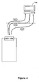
- FIG. 1 shows an example of a computer network which implements a first embodiment of the present invention.
- the computer network includes a customer's PC 10 which can be connected to a first enterprise's web server computer 12A, via the Internet 14.
- the first enterprise's server is in turn connected to an administration computer 16A and a utility services server computer 18A by a private network 20.
- the web server computer 12A includes Trusted Platform Module hardware as described in the Trusted Computing Group's 'TCG Generic Server Specification' version 1.0.
- Enterprise A's computers and its favoured security token service computer 22A are regarded as belonging to a first trust realm A.
- the customer's PC 10 is provided with browser software which enables the customer to interact with the web-server 12A.
- a browser might be installed from CD-ROM A.
- Such browser software is well known and will not be described further.
- the first enterprise's web server computer 12A is provided with virtualization software like the open source Xen hypervisor available from www.xensource.com which supports a virtual TPM implementation (as disclosed in IBM Research Report RC23879 - 'vTPM: Virtualizing the Trusted Platform Module') and further discussed in the web-page 'Virtual Trusted Platform Module' found at http://domino.research.ibm.com/comm/research_projects.nsf/pages/ssd_vtpm.index.html
- Such virtualisation software is installed on the web server 12A from CD-ROM B. Installation of this software has the result that the Trusted Platform Module's secure storage and cryptographic functions are available to each virtual machine created on the web server 12A.
- a similar set of computers (12B, 16B, 18B) provided with similar software and belonging to enterprise B are also connected to the Internet 14.
- Enterprise B's computers are regarded as belonging to a first trust realm B.
- the installation of the virtual TPM software initially generates a Virtual Machine Monitor and a Base Service Manager that controls the setting up of further virtual machines.
- the Base Service Manager has the information to authenticate each virtual machine and (by matching the keys-related information) can control access to/from different virtual machines.
- the Base Service Manager provides an administration interface. It will be understood that this interface might be used by an administrator using administration computer 16A to manipulate the operation of the web server 12A.
- the Base Service Manager provides TCP/IP communications stack software which receives messages from and transmits messages to one or more network interface cards that each Web Server 12A, 12B computer has. As a consequence, all incoming and outgoing messages are exposed to the Base Service Manager. These messages are sent between the computers using the HyperText Transfer Protocol.
- the Base Service Manager recognises HTTP requests and responses which contain XML and extracts the XML from such messages - it will be understood by those skilled in the art that handlers which convert HTTP requests and responses to XML are well-known.
- PEP VM Policy Enforcement Point virtual machine
- GTH VM Group Token Handler virtual machine
- the Group Token Handler virtual machine stores a table (initially empty) which lists, for each web service instance on the web server, group membership tokens available to each web service.
- table initially empty
- web service WS1 has group membership tokens for groups g1 and g2
- web service WSN has group membership tokens for group g1 only.
- the way in which group tokens are added to the table will be described below with reference to Figures 5A and 5B .
- the way in which group tokens are removed from the table (and thereby revoked) will be described below with reference to Figure 6 .
- the security programs include a core enforcement component to which the Base Service Manager passes all XML messages arriving at the server computer 12A.
- the core enforcement component includes an XML processor able to process an XML stream (in this embodiment the XML processor is provided by the SAX software package).
- the computer's administrator then loads, from CD-ROM D, code for the various local interceptors used in processing incoming or outgoing SOAP messages onto an interceptor repository stored within the PEP VM.
- an important advantage of the use of separate virtual machines relates to the containment of interference, and separation of concerns between PEP, GTH and WS partitions. This allows for different a substantially strong form of access and execution separation between these partitions. Consequently an WS administrator or the WS code itself will not be able to interfere with the PEP partition. Similarly an infrastructure administrator will not be able to directly or indirectly access or interfere with the group tokens or the application code and a collaboration manger will not be able to directly or indirectly access the PEP handlers or chain or the WS code.
- PEPs Policy Enforcement Points
- PEPs are responsible intercepting the message and for enforcing series of enforcement actions in compliance with some configuration policy. This process could include for example, checking the signature, performing decryption of certain parts of the message, verifying the content of the message, checking for the presence of group tokens etc.
- the message is delivered to the recipient only after the PEP verifies that the message complies with the PEP configuration policy.
- the enforcement actions that the PEP needs to perform are implemented by SOAP Interceptors and can be sequentially grouped together into something called interceptor chains.
- the enforcement process is based upon the composition of interceptor chains which is a process based on the amalgamation of the message content analysis and the security requirements of the protected resource derived form the configuration policy. Based on the outcome of this fusion the selected interceptors are inserted into the chain.
- the interceptors in a chain may be deployed locally or they can be distributed over the network and be invoked remotely.
- the PEP virtual machine is loaded with software providing such a Policy Enforcement Point.
- the administration computer 16A has a Web-Service Distributed Management implementation such as Apache MUSE or any other implementation that supports WSDM protocol stack (e.g. IBM Websphere, CA WSDM) or the WS-Management stack (e.g. Microsoft .NET WSE) installed upon it from CD-ROM E (it will be realised that WS is a common abbreviation for Web Services).
- WSDM protocol stack e.g. IBM Websphere, CA WSDM
- WS-Management stack e.g. Microsoft .NET WSE
- This enables an administrator to load configuration files and policies into the web-server computer 12A in order to control its operation as will be described below (policies are normally more dynamic that configuration files - i.e. more frequently updated - especially they are often updated during the execution of the application they control).
- the administrator can load policies which are not specific to a given instance of a web-service into the PEP VM.
- the administrator might load the interceptor reference policy (IRP), and the Utility Service Policy (USP) described in the applicant's co-pending international application WO 2006/011943 .
- IRP interceptor reference policy
- USP Utility Service Policy
- the utility service server computer 18A is provided with software providing one or more utility services (e.g. certificate verification, security token validation) from CD-ROM F.
- the utility service computer 18A is provided with software that enables it to act as a Security Token Service (STS).
- STS Security Token Service
- Enterprise A collaborates with Enterprise B in order to provide the customer with a desired service.
- Enterprise B has a similar set of similarly programmed computers to Enterprise A.
- the web servers of the enterprises involved in the collaboration can provide a distributed application by sending messages between separate components which are combined together to form the distributed application.
- these software components take the form of web services.
- the administrator of each of the web server computers 12A and 12B controls the virtual TPM hypervisor software to create one or more virtual machines, each of which is intended to host a single instance of a web service.
- the administrator loads the local components and any underlying software needed to run it. For example if the Web Service were written in Java then the administrator would also load Apache Tomcat software or Apache Axis software. If, alternatively, the Web Service were a .NET component then the administrator would also load Microsoft VStudio, or Microsoft WSE.
- the virtual TPM included with the virtual machine creates a key pair for the WS instance.
- the public key of this pair is then advertised as the public key of the WS instance and the private part is encrypted with the Storage Root Key (SRK) of the virtual TPM. Any data sent for the WS instance can then be encrypted with this public key.
- SRK Storage Root Key
- Any data sent for the WS instance can then be encrypted with this public key.
- a "signature" key-pair can be created for each service instance.
- an arbitrary number of the "crypto" material, secret(s) etc. can be created for various purposes and protected by the virtual TPM as the private key above.
- the public key(s) of the key-pair(s) could be signed by the attestation key of the virtual TPM (whose key could in turn be signed by the TPM of the Base Service Manager). This is particularly useful for security auditing and traceability of the creation and management of virtual machines on the web servers 12A and 12B.
- each administrator installs the web services used in providing the service (it will be understood that these will normally differ between the two web servers) and configures those web services appropriately. It is to be understood that loading the web services into different virtual machines provides the advantage of secure isolation between several distinct exposures of a (web) service of the same type - and indeed between web services of a different type. As is well known in the art, the web services will exchange messages between them using the Simple Object Access Protocol.
- the service-specific policy i.e. the Enforcement Configuration Policy in the language of the TrustCOM deliverables, will be loaded by the administrator into the PEP virtual machine using the interface provided for that purpose on administration computer 16A.
- Enforcement Configuration Policy and the other policies mentioned above has the beneficial result that the behaviour of the security programs in relation to a given distributed application can be changed with immediate effect and without the need to redeploy or restart the protected resources or any other part of the system.
- a web service partition is provided with ( Figure 4 ) an identity token by the administrator.
- WS1(A) VM sends a request M 1 to local domain administrator 16A asking for a local domain membership token.
- the request contains the Public key of the virtual TPM of WS1 (A) VM, the end-point reference (EPR) of the web service instance and a signature on these values using the Attestation key of the virtualized TPM. Since the local administration and web service instance do not run on the same instance of Trusted Platform Module hardware, a second round of signature chain is added to the request message to prove the validity of the attestation key of WS1 (A) VM's virtual TPM.
- Local administration computer 16A might in turn run a challenge response protocol (step 302) to make sure that the TPM of WS1 (A)'s partition does indeed own the private key of the public key supplied. If this is verified successfully, local administration computer 16A sends web service instance identity token T 1 back to WS1 (A) (step 303).
- T 1 Pu WS ⁇ 1 A , EPR WS ⁇ 1 A , Pu ADMIN A , EPR ADMIN A , Sign ⁇ Pu WS ⁇ 1 A ⁇ EPR WS ⁇ 1 A ADMIN A , Sign ⁇ Pu ADMIN A TTP , other_details
- Figures 5A and 5B show the message exchange which results in a WS instance having a group token stored for its use in the local Group Token Handler virtual machine.
- the group token includes an identifier of the group participant, such as Web service ID.
- PDP Policy Decision Point
- the former two terms are used in accordance with the WS-Addressing standard.
- each of these pieces of functionality are provided on local administration computers 16A and 16B.
- the Security Token Service functionality is provided by the utility computers 18A and 18B.
- step 1 WS1(A) requests the activation of a new web service group by sending a message to the activation service.
- 'signPrws1(A)' indicates that the data inside the curly brackets is digitally signed using the Private Key Prws1 (A). In other words, the data inside the curly brackets is digitally signed by the web service WS1 (A)).
- step 2 the activation service creates a group identifier or descriptive part (GC) of a so-called security context for the group, and passes it to the web service 1.
- the group identifier is 'g1'.
- step 3 the activation service communicates with the STS A, requesting the creation of a group key pair for the new group.
- message 3 GroupID , KeyPairCreateRequest , Tws ⁇ 1 A ⁇ signPa
- the Security Token Service A responds to the message by creating a group key pair for this context (Prg1/Pug1 - Prg1 being a private key used by members of new group g1, Pug1 being the corresponding public key).
- step 7 the STS A sends (either directly or via registration service), the group membership token Tws1(A)-g1 to the group token handler virtual machine.
- the message is digitally signed by the STS A.
- message 7 Tws ⁇ 1 A - g ⁇ 1 ⁇ signPrstsA
- the group token handler receives this message, finds the relevant record in the group membership list ( Figure 3 ) using the web instance ID found in the group token and adds the group token to the list of group memberships associated with that web instance in that table.
- step 8 the STS A sends (either directly or via the registration service), the group private key Prg encrypted with the public key of the ws1 (A) and digitally signed by the STS A.
- message 8 Prg / encPuws ⁇ 1 A , GroupID , Pug ⁇ 1 ⁇ signPrstsA
- the web service is provided with the group private key, whilst the group membership token is supplied to the group token handler virtual machine (GTH(A) VM).
- the web service WS1(A) is now a full member of the group.
- Figure 5B shows the message exchanges that take place when a web service instance (in this particular example, web service WS1(A)) on enterprise A's web-server 12A wishes to invite a web service instance (say WS1(B)) on enterprise B's web-server 12B to join a group of which WS1 (A) is already a member.
- a web service instance in this particular example, web service WS1(A)
- web service WS1(B) wishes to invite a web service instance (say WS1(B)) on enterprise B's web-server 12B to join a group of which WS1 (A) is already a member.
- WS1 (A) had received the group identifier GC, and the group public and private key, and the Group Token Handler virtual machine (GTH(A) VM) had received a personalised group token Tws1 (A)-g1 and stored it in its group membership table ( Figure 3 ).
- WS1(A) sends an application message to WS1(B) to pass the descriptive part of the context (GC), and the address of registration service A to WS1(B).
- the application message also contains an Add Group Token Request.
- message 9 WS ⁇ 1 B _ID / signPrg , GC , RegAdrA , Add Group Token Request
- outgoing SOAP messages from web service instance virtual machines are intercepted by the Policy Enforcement Point virtual machine.
- the SOAP message includes an Add Group Token Request
- the GTH virtual machine will check using the group membership table ( Figure 3 ) whether the web service sending the message is a member of the group and add a Group Token to the message if it is a member.
- the message is then forwarded to the original addressee, in this case WS1(B).
- message 10 WS ⁇ 1 B _ID / signPrg , GC , RegAdrA , Tws ⁇ 1 A - g ⁇ 1
- the WS1(B) is configured to use a different coordination service, it sends request to the activation service B. This is different from the initial message 1 ( Figure 5A ) from WS1(A), as it contains the group context GC, created by Activation Service A and received from WS1(A).
- activation service B returns the same GC, and provides the addresses for registration service B.
- the address of Registration Service A is received by WS1(B) from WS1(A), and is therefore passed to the registration service B with the registration request.
- WS1(B) sends a registration request to the registration service B using the address received from activation service B in step 12.
- the Registration service A responds. However, the private key for the group is sent to the STS B in a separate communication (messages 16-18 below).
- message 14 ⁇ b message 10 ⁇ signPrrb
- federation between realms A and B needs to be established at this point in step 16 so that delivery of the group private key to WS1(B) can take place.
- step 17 the key pair for the group is delivered from STS A to STS B; it is stored at STS B to be used as a part of the group token for every service from trust realm B that needs to join the group.
- step 18 after performing security check on the WS1(B) at the responsible STS and PDP services, registration service B communicates with the STS B, requesting creation of the group token for WS1(B) (Tws1(B)-g1) and delivery of Tws1(B)-g1 to the group handler virtual machine GTH(B) VM on enterprise B's web-server and the group private key Prg to WS1(B).
- Tws1(B)-g1 contains an identifier of the service that is successfully registered with the group.
- step 19 The STS B signs and returns the personalised group token Tws1(B)-g1to the Group Token Handler VM (GTH(B) VM) on enterprise B's web server 12B.
- message 19 ⁇ Tws ⁇ 1 B - g ⁇ 1 ⁇ signPrstsb
- the group token handler makes an entry in its group membership list which records the fact that WS1 (B) is a member of group g1.
- step 20 the STS B signs and returns the private group key Prg encrypted with the public key of the WS1 (B) to the web service instance WS1 (B).
- message 20 Prg / encPuws ⁇ 1 B ⁇ signPrstsb
- the second web service WS1(B) is then also a full group participant of group g1, and group communication at the application-level can take place between group participants, protected with the security context.
- Each message also includes the corresponding group token, allowing for peer authentication.
- WS2(B) can be registered with registration service B and receive a private key from STS B and GTH(B) VM can receive a personalised group token Tws1(B)-g1 from the STS B.
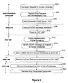
- Figure 6 shows how an administrator can revoke a credential which has been issued to a web service in the trust realm which the administrator administers.
- Software on the administration computer 16A, 16B provides a graphical user interface which allows the administrator to select a personalised group membership token to be revoked.
- a request to revoke that group membership token is thus generated (step 602).
- the request includes an identifier for the web service instance and the personalised group membership token.
- the revocation request is then signed with the administrator's private key (step 604) and sent (step 606) to the web server 12A.
- the revocation request is received and passed to the Base Service Manager virtual machine.
- the Base Service Manager virtual machine detects (step 608) the arrival of a SOAP message and forwards (step 610) it to the Policy Enforcement Point virtual machine.
- the Policy Enforcement Point verifies (step 612) the administrator's signature on the revocation request, identifies (step 614) the request as a revocation request and then passes (step 616) the message back to the Base Service Manager virtual machine, giving an indirect address for the group token handler virtual machine (GTH VM).
- GTH VM group token handler virtual machine
- the Base Service Manager then resolves that indirect address into a genuine internal address and forwards the revocation request to the group token handler virtual machine (step 618).
- the Group Token Handler virtual machine then reads the web service instance and personalised group membership token from the revocation request, and deletes (step 622) the corresponding entry from its group membership list ( Figure 3 ) if such an entry is present.
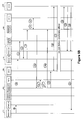
- Figures 7A and 7B show the message exchange and processing that takes place when a web service instance attempts to send a message to a member of a group of web service instances (i.e. it shows the message processing that takes place each time a message like message 21 in Figure 5B is sent).
- the web service instance creates (step 702) a SOAP message which is for sending to another web service which co-operates in the performance of some distributed application.
- the SOAP message includes, in its header, a group identifier which identifies the group which corresponds to the web services involved in this particular distributed application.
- the web service instance encrypts (step 704) the payload of the message using a public key which is itself generated by the virtual TPM functionality of the destination web service instance virtual machine.
- the partially-encrypted message is then sent (step 706) to the Base Service Manager.
- the Base Service Manager forwards the message to the Policy Enforcement Point virtual machine (step 708).
- the PEP VM On receipt by the Policy Enforcement Point virtual machine, the PEP VM reads the end-point reference from the SOAP message header (step 710), finds the appropriate Enforcement Configuration Policy and creates (step 714) a dynamic handler chain in which a sequence of handlers, selected and ordered in accordance with that policy are used to process the message.
- the handlers at the end of the chain is a handler which seeks to add a group membership token (for the group identified in the header of the SOAP message) to the outgoing message.
- This handler generates a request (step 716), indirectly addressed to the Group Token Handler virtual machine for a group token to be added to the outgoing message. That request includes the group identifier found in the header of the SOAP message.
- the group token handler virtual machine On receiving the request, the group token handler virtual machine looks in its group membership list ( Figure 3 ) for the web service instance from which the SOAP message originates, to see whether a group membership token for the group in question is present.
- step 720 If no such token is present, then it cannot be added to the message and the handler terminates (step 720). If the token is present, then it is added to the message (step 722). The outgoing message is then forwarded to the Base Service Manager (step 724) which encrypts the SOAP message header using the destination PEP VM's public key (step 726) and sends (step 728) the encrypted SOAP message as the payload of an HTTP message sent to the IP address of the other web server.
- the Base Service Manager step 724 which encrypts the SOAP message header using the destination PEP VM's public key (step 726) and sends (step 728) the encrypted SOAP message as the payload of an HTTP message sent to the IP address of the other web server.
- a computer network in which a group of computers co-operate to perform a distributed application.
- messages sent in the performance of the distributed application are checked by the recipient for the presence of a group membership token.
- the inclusion of a group membership token is controlled by one or more group membership handlers which intercept messages from local components and only include a group membership token with the message if they list the sending local component as being entitled to include the group membership token in the message.
- security is further improved.
- the group token handler and/or the local component are hosted on virtual machines which provide virtualised cryptographic functionality.
Abstract
A computer network is disclosed in which a group of computers co-operate to perform a distributed application. In order to ensure that only members of that group of computers are able to carry out certain operations, messages sent in the performance of the distributed application are checked by the recipient for the presence of a group membership token. The inclusion of a group membership token is controlled by one or more group membership handlers which intercept messages from local components and only include a group membership token with the message if they list the sending local component as being entitled to include the group membership token in the message. Furthermore, by operating the group membership token on a separate machine, or preferably a separate virtual machine from the local component, security is further improved. In the most preferred embodiments, the group token handler and/or the local component are hosted on virtual machines which provide virtualised cryptographic functionality.

Description
- The present invention relates to a computer network and a method of operating a computer network.
- The advent of the Internet has meant that it is now much more common for groups of computers to co-operate with one other in some sort of common endeavour. Examples include distributed application programs, different parts of which run on different computers connected to the computer network. The most widely-researched distributed application programs are programs which integrate 'Web Services' running on different computers. 'Web Services' are one example of components that might be assembled in accordance with a 'Service Oriented Architecture'. Other known technologies might be used in place of Web Services - e.g. Enterprise Java Beans or components constructed in accordance with the Common Object Request Broker Architecture.
- There is a need for security in such systems. This is especially true of inter-enterprise distributed application programs where computers in one enterprise co-operate with computers in a different enterprise. Whilst an enterprise's system administrator might trust computers administered by that enterprise not to behave maliciously, he is much less likely to trust computers administered by another enterprise to do so.
- One important safeguard against malicious operation is operating each computer participating in running a distributed application to respond to receiving a message claiming to be from another participating computer by first verifying the authenticity of that claim before acting upon the message. Should the authenticity of the claim be found to be in doubt, then the receiving computer might do nothing or issue an alert to the system administrator.
- Authentication is often provided using so-called credentials - most commonly a digital certificate digitally signed by a trusted authority. A problem with such credentials is handling their revocation. Conventionally this is done using Certificate Revocation Lists which a person receiving a certificate is expected to check prior to relying on that certificate. Alternatively, or in addition, the lifetime of certificate can be made short so that a certificate which is not renewed quickly becomes invalid in any case.
- Returning to authentication in distributed applications, whilst it would be possible to require the computer sending the message to authenticate itself individually, it is often sufficient to have the computer sending the message to authenticate itself as a participant without specifically indicating which of the participant computers it is. This provides a more scalable method of authentication.
- The applicant's co-pending European patent application
06251031.8 - As with all schemes involving 'certificate revocation lists', the problem arises that the security of the whole system then additionally depends on the security of whatever protocol is used to store such lists and transmit information from such lists to the point of use.
- According to the present invention, there is provided a computer network comprising a plurality of local components, a group of which interact by passing messages between them in order to perform a distributed application, in which one or more of said computers comprises:
- a local-component-hosting execution environment arranged in operation to execute one or more local components of the distributed application;
- a group membership token handler in a separate execution environment including a group membership token store storing one or more group membership tokens for said local distributed application components and information indicating which components are entitled to include the group membership tokens in their messages, said group membership token handler being arranged in operation to intercept one or more message transmissions from a local components to other computers in said network, to find whether the message-sending local component is entitled to include a group membership token asserting membership of the group with the message, and to include the group membership token with the intercepted message if said local component is entitled to the group membership component;
- a group membership controller providing an interface that enables a token authority to update said group membership token store in order to change which local components are entitled to have a group membership token including with one or more messages.
- By providing a separate execution environment which includes group membership tokens with distributed application messages sent by components of that distributed application provided a group token membership store includes a group membership token indicated to be available for the sending component, and providing a token authority with an interface enabling the group token membership store to be updated, a method of controlling group membership which provides more secure group membership verification than has hitherto been achieved is enabled.
- The separate execution environments could be different computers in said computer network, but preferably the separate execution environments are in different partitions or virtual machines hosted on the same computer.
- By placing the group membership token handler on the same computer as the local component, but having the two execute in different virtual machines, the security benefits of isolating the local component from the group membership token handler are maintained whilst the power and amount of equipment required to provide a computer network supporting the distributed application are reduced.
- Preferably, the virtual machines provide one or more virtual cryptoprocessor functions.
- Then, by using encryption based on keys stored exclusively in said virtual machine, message security (i.e. one or more of message confidentiality, integrity, authenticity and non-repudiability) can be further improved.
- Preferably, said group membership tokens comprise personalised group membership tokens.
- There now follows, by way of example only, a description of a specific embodiment of the present invention. The description refers to the attached drawings in which:
-
Figure 1 shows a group of web server computers co-operating to form a virtual organisation in order to perform a service for a customer interacting with that virtual organisation using his personal computer; -
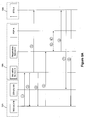
Figure 2 shows how each web server is virtualised to provide a plurality of partitions; and -
Figure 3 shows a group token membership data structure stored in a group token handling partition; -
Figure 4 shows how each web service instance can obtain an individual identity token from a local administration computer; -
Figure 5A shows how a web service instance can later obtain a group membership token; -
Figure 5B shows how a web service running on the other web server can be invited to join the group and thus obtain a group membership token; -
Figure 6 shows the processes involved in revoking a group membership token after it has been issued; -
Figures 7A and7B shows the steps involved in applying a group membership token to a message sent by a member of the group. -
Figure 1 shows an example of a computer network which implements a first embodiment of the present invention. The computer network includes a customer's PC 10 which can be connected to a first enterprise'sweb server computer 12A, via the Internet 14. The first enterprise's server is in turn connected to anadministration computer 16A and a utilityservices server computer 18A by aprivate network 20. Theweb server computer 12A includes Trusted Platform Module hardware as described in the Trusted Computing Group's 'TCG Generic Server Specification' version 1.0. Enterprise A's computers and its favoured security token service computer 22A are regarded as belonging to a first trust realm A. - The customer's PC 10 is provided with browser software which enables the customer to interact with the web-
server 12A. A browser might be installed from CD-ROM A. Such browser software is well known and will not be described further. - The first enterprise's
web server computer 12A is provided with virtualization software like the open source Xen hypervisor available from www.xensource.com which supports a virtual TPM implementation (as disclosed in IBM Research Report RC23879 - 'vTPM: Virtualizing the Trusted Platform Module') and further discussed in the web-page 'Virtual Trusted Platform Module' found at
http://domino.research.ibm.com/comm/research_projects.nsf/pages/ssd_vtpm.index.html - Alternatively, software as disclosed in
US Patent application 2005/0246552 might be provided. As yet another alternative, the software disclosed in international patent applicationWO 2006/011943 might be used. - Such virtualisation software is installed on the
web server 12A from CD-ROM B. Installation of this software has the result that the Trusted Platform Module's secure storage and cryptographic functions are available to each virtual machine created on theweb server 12A. - A similar set of computers (12B, 16B, 18B) provided with similar software and belonging to enterprise B are also connected to the Internet 14. Enterprise B's computers are regarded as belonging to a first trust realm B.
- Referring to
Figure 2 , the installation of the virtual TPM software initially generates a Virtual Machine Monitor and a Base Service Manager that controls the setting up of further virtual machines. The Base Service Manager has the information to authenticate each virtual machine and (by matching the keys-related information) can control access to/from different virtual machines. - The Base Service Manager provides an administration interface. It will be understood that this interface might be used by an administrator using
administration computer 16A to manipulate the operation of theweb server 12A. The Base Service Manager provides TCP/IP communications stack software which receives messages from and transmits messages to one or more network interface cards that eachWeb Server - Thereafter, the computer's administrator creates a Policy Enforcement Point virtual machine (PEP VM) and a Group Token Handler virtual machine (GTH VM). The setting up of the other virtual machines seen in
Figure 2 (WS VM) will be explained below in relation to the deployment of a distributed application which combines web services running onweb servers - The Group Token Handler virtual machine stores a table (initially empty) which lists, for each web service instance on the web server, group membership tokens available to each web service. In the example shown in
Figure 3 , web service WS1 has group membership tokens for groups g1 and g2, whereas web service WSN has group membership tokens for group g1 only. The way in which group tokens are added to the table will be described below with reference toFigures 5A and5B . The way in which group tokens are removed from the table (and thereby revoked) will be described below with reference toFigure 6 . - Having set up the PEP VM one or more message handling programs (referred to as 'interceptors' or 'handlers' in the present embodiment) are installed on that virtual machine from CD-ROM C. The security programs include a core enforcement component to which the Base Service Manager passes all XML messages arriving at the
server computer 12A. The core enforcement component includes an XML processor able to process an XML stream (in this embodiment the XML processor is provided by the SAX software package). - The computer's administrator then loads, from CD-ROM D, code for the various local interceptors used in processing incoming or outgoing SOAP messages onto an interceptor repository stored within the PEP VM.
- Having a PEP virtual machine shared by multiple virtual machines running web service components for different distributed applications leads to a reduction in the amount of storage space required at the node since those routines need only be stored once rather than on each separate virtual machine. Since a library of such routines must include routines for all the routines which might be called, this represents a significant memory saving.
- In general, an important advantage of the use of separate virtual machines relates to the containment of interference, and separation of concerns between PEP, GTH and WS partitions. This allows for different a substantially strong form of access and execution separation between these partitions. Consequently an WS administrator or the WS code itself will not be able to interfere with the PEP partition. Similarly an infrastructure administrator will not be able to directly or indirectly access or interfere with the group tokens or the application code and a collaboration manger will not be able to directly or indirectly access the PEP handlers or chain or the WS code.
- Furthermore different operating, systems & can be used for executing PEP or WS application or for storing group tokens.
- As described by the adaptive enforcement architecture that has been presented in the TrustCOM deliverables D19 and D29-35-36 before a SOAP message is delivered to a web service instance, it is passed through a number of Policy Enforcement Points (PEPs). PEPs are responsible intercepting the message and for enforcing series of enforcement actions in compliance with some configuration policy. This process could include for example, checking the signature, performing decryption of certain parts of the message, verifying the content of the message, checking for the presence of group tokens etc. The message is delivered to the recipient only after the PEP verifies that the message complies with the PEP configuration policy. The enforcement actions that the PEP needs to perform are implemented by SOAP Interceptors and can be sequentially grouped together into something called interceptor chains. The enforcement process is based upon the composition of interceptor chains which is a process based on the amalgamation of the message content analysis and the security requirements of the protected resource derived form the configuration policy. Based on the outcome of this fusion the selected interceptors are inserted into the chain. The interceptors in a chain may be deployed locally or they can be distributed over the network and be invoked remotely. In the present example, the PEP virtual machine is loaded with software providing such a Policy Enforcement Point.
- The
administration computer 16A has a Web-Service Distributed Management implementation such as Apache MUSE or any other implementation that supports WSDM protocol stack (e.g. IBM Websphere, CA WSDM) or the WS-Management stack (e.g. Microsoft .NET WSE) installed upon it from CD-ROM E (it will be realised that WS is a common abbreviation for Web Services). This enables an administrator to load configuration files and policies into the web-server computer 12A in order to control its operation as will be described below (policies are normally more dynamic that configuration files - i.e. more frequently updated - especially they are often updated during the execution of the application they control). - Using that interface, the administrator can load policies which are not specific to a given instance of a web-service into the PEP VM. In particular, the administrator might load the interceptor reference policy (IRP), and the Utility Service Policy (USP) described in the applicant's co-pending international application
WO 2006/011943 . - The utility
service server computer 18A is provided with software providing one or more utility services (e.g. certificate verification, security token validation) from CD-ROM F. In particular theutility service computer 18A is provided with software that enables it to act as a Security Token Service (STS). - As was mentioned above, in this example, Enterprise A collaborates with Enterprise B in order to provide the customer with a desired service. Enterprise B has a similar set of similarly programmed computers to Enterprise A. The web servers of the enterprises involved in the collaboration can provide a distributed application by sending messages between separate components which are combined together to form the distributed application.
- There is a need for modern enterprises to rapidly introduce new products and services to the marketplace. This requires the ability to quickly assemble software components to provide a distributed application which provides or assists in providing the new product or service to the customer.
- In the present example, these software components take the form of web services. In order to provide a platform for the introduction of web services, the administrator of each of the
web server computers - Once the virtual machine for the WS instance is built, the virtual TPM included with the virtual machine creates a key pair for the WS instance. The public key of this pair is then advertised as the public key of the WS instance and the private part is encrypted with the Storage Root Key (SRK) of the virtual TPM. Any data sent for the WS instance can then be encrypted with this public key. In addition, a "signature" key-pair can be created for each service instance. In general, an arbitrary number of the "crypto" material, secret(s) etc. can be created for various purposes and protected by the virtual TPM as the private key above.
- The public key(s) of the key-pair(s) could be signed by the attestation key of the virtual TPM (whose key could in turn be signed by the TPM of the Base Service Manager). This is particularly useful for security auditing and traceability of the creation and management of virtual machines on the
web servers - Then, at the time of deployment of the new distributed application to support the new product or service, each administrator installs the web services used in providing the service (it will be understood that these will normally differ between the two web servers) and configures those web services appropriately. It is to be understood that loading the web services into different virtual machines provides the advantage of secure isolation between several distinct exposures of a (web) service of the same type - and indeed between web services of a different type. As is well known in the art, the web services will exchange messages between them using the Simple Object Access Protocol. At the time that virtual machine is created, the service-specific policy -i.e. the Enforcement Configuration Policy in the language of the TrustCOM deliverables, will be loaded by the administrator into the PEP virtual machine using the interface provided for that purpose on
administration computer 16A. - The use of the Enforcement Configuration Policy and the other policies mentioned above has the beneficial result that the behaviour of the security programs in relation to a given distributed application can be changed with immediate effect and without the need to redeploy or restart the protected resources or any other part of the system.
- As part of its initial configuration, a web service partition is provided with (
Figure 4 ) an identity token by the administrator. - In
step 301, WS1(A) VM sends a request M1 tolocal domain administrator 16A asking for a local domain membership token. The request contains the Public key of the virtual TPM of WS1 (A) VM, the end-point reference (EPR) of the web service instance and a signature on these values using the Attestation key of the virtualized TPM. Since the local administration and web service instance do not run on the same instance of Trusted Platform Module hardware, a second round of signature chain is added to the request message to prove the validity of the attestation key of WS1 (A) VM's virtual TPM.
-
Local administration computer 16A might in turn run a challenge response protocol (step 302) to make sure that the TPM of WS1 (A)'s partition does indeed own the private key of the public key supplied. If this is verified successfully,local administration computer 16A sends web service instance identity token T1 back to WS1 (A) (step 303).
Where:
PUWS1(A) - public key of WS1 (A)
TTP - trusted third party - e.g. VeriSign
'other_details' - all other required details like validity time period etc. -
Figures 5A and5B show the message exchange which results in a WS instance having a group token stored for its use in the local Group Token Handler virtual machine. In this case, the group token includes an identifier of the group participant, such as Web service ID. Those skilled in the art will be familiar with the functional blocks 'activation service', 'registration service', Policy Decision Point (PDP). The former two terms are used in accordance with the WS-Addressing standard. In this example, each of these pieces of functionality are provided onlocal administration computers utility computers - In (
Figure 5A )step 1, WS1(A) requests the activation of a new web service group by sending a message to the activation service. The identity token of WS1(A) is provided to authenticate itself at the activation service:
- In
step 2, the activation service creates a group identifier or descriptive part (GC) of a so-called security context for the group, and passes it to theweb service 1. In this particular example, the group identifier is 'g1'. - In
step 3, the activation service communicates with the STS A, requesting the creation of a group key pair for the new group.
- The Security Token Service A responds to the message by creating a group key pair for this context (Prg1/Pug1 - Prg1 being a private key used by members of new group g1, Pug1 being the corresponding public key).
- In
step 4, the activation service returns the group identifier GC (='g1' in this case), and the address of the Registration service to the web service WS1(A) which initiated the group creation request:
- In
step 5, the service WS1(A) requests registration with the context, that is participation in the group, from the Registration service:
- In
step 6, the registration service performs a security check on the WS1(A) at the responsible STS and PDP services by presenting the identity token of WS1(A), and communicates with the STS A, requesting creation of the group token for WS1(A) (Tws1(A)-g1) and delivery of the group token Tws1(A)-g1 to GTH(A) VM and Prg1 to the service WS1(A):


Note that in this case the group token contains an identifier of the service that is successfully registered with the group, as well as the public key.
Instep 7, the STS A sends (either directly or via registration service), the group membership token Tws1(A)-g1 to the group token handler virtual machine. The message is digitally signed by theSTS A. 
- The group token handler receives this message, finds the relevant record in the group membership list (
Figure 3 ) using the web instance ID found in the group token and adds the group token to the list of group memberships associated with that web instance in that table. - In
step 8, the STS A sends (either directly or via the registration service), the group private key Prg encrypted with the public key of the ws1 (A) and digitally signed by theSTS A. 
- Thus, the web service is provided with the group private key, whilst the group membership token is supplied to the group token handler virtual machine (GTH(A) VM). The web service WS1(A) is now a full member of the group.
-
Figure 5B shows the message exchanges that take place when a web service instance (in this particular example, web service WS1(A)) on enterprise A's web-server 12A wishes to invite a web service instance (say WS1(B)) on enterprise B's web-server 12B to join a group of which WS1 (A) is already a member. - At the end of
step 8 above, WS1 (A) had received the group identifier GC, and the group public and private key, and the Group Token Handler virtual machine (GTH(A) VM) had received a personalised group token Tws1 (A)-g1 and stored it in its group membership table (Figure 3 ). - In step 9, WS1(A) sends an application message to WS1(B) to pass the descriptive part of the context (GC), and the address of registration service A to WS1(B). The application message also contains an Add Group Token Request. There is no need to pass identity token of WS1 (B):

- As will be explained in more detail with reference to
Figures 7A and7B , outgoing SOAP messages from web service instance virtual machines are intercepted by the Policy Enforcement Point virtual machine. Where, as in this case, the SOAP message includes an Add Group Token Request, the GTH virtual machine will check using the group membership table (Figure 3 ) whether the web service sending the message is a member of the group and add a Group Token to the message if it is a member. Instep 10, the message is then forwarded to the original addressee, in this case WS1(B).
- In
Step 11, the WS1(B) is configured to use a different coordination service, it sends request to the activation service B. This is different from the initial message 1 (Figure 5A ) from WS1(A), as it contains the group context GC, created by Activation Service A and received from WS1(A). Instep 12, activation service B returns the same GC, and provides the addresses for registration service B. The address of Registration Service A is received by WS1(B) from WS1(A), and is therefore passed to the registration service B with the registration request.

- There is no need for Activation Service B to contact the STS B at this stage (as happened with
message 3 for the actions of WS1(A)), since the key pair for the group already exists and will be delivered to STS B in one of the following steps. - In
step 13, WS1(B) sends a registration request to the registration service B using the address received from activation service B instep 12. The address of registration service A is also transmitted:
- In
step 14 the Registration Service B communicates with the PDP B to verify that WS1(B) is authorised to join the group:

- If this is okay, the registration service B registers with the registration service A as interposed, on behalf of the service WS1 (B):

- The registration service A then communicates with the PDP A to verify that it can accept the interposed registration:


- If this is okay, the Registration service A responds. However, the private key for the group is sent to the STS B in a separate communication (messages 16-18 below).
- If there is a requirement to additionally guarantee the integrity and non-repudiation of the interactions between WS1(B) and registration service B (i.e. between a participant of the interposed registration service and the interposed registration service), then the
original message 13 should be co-signed by registration service B, in order to formmessage 14b:
- In
step 15, the registration service A communicates with the STS A to pass the key pair for the group to the STS B:
- If not already completed, federation between realms A and B needs to be established at this point in
step 16 so that delivery of the group private key to WS1(B) can take place. - In
step 17, the key pair for the group is delivered from STS A to STS B; it is stored at STS B to be used as a part of the group token for every service from trust realm B that needs to join the group. - In
step 18, after performing security check on the WS1(B) at the responsible STS and PDP services, registration service B communicates with the STS B, requesting creation of the group token for WS1(B) (Tws1(B)-g1) and delivery of Tws1(B)-g1 to the group handler virtual machine GTH(B) VM on enterprise B's web-server and the group private key Prg to WS1(B).

- Note that Tws1(B)-g1 contains an identifier of the service that is successfully registered with the group.
- In
step 19, The STS B signs and returns the personalised group token Tws1(B)-g1to the Group Token Handler VM (GTH(B) VM) on enterprise B'sweb server 12B.
- The group token handler makes an entry in its group membership list which records the fact that WS1 (B) is a member of group g1.
- In
step 20, the STS B signs and returns the private group key Prg encrypted with the public key of the WS1 (B) to the web service instance WS1 (B).
- The second web service WS1(B) is then also a full group participant of group g1, and group communication at the application-level can take place between group participants, protected with the security context. Each message also includes the corresponding group token, allowing for peer authentication. The message below is directed from WS1(A) to WS1(B):

- If a service WS2(B) from realm B wants subsequently to join the group,
messages -
Figure 6 shows how an administrator can revoke a credential which has been issued to a web service in the trust realm which the administrator administers. - Software on the
administration computer - The revocation request is then signed with the administrator's private key (step 604) and sent (step 606) to the
web server 12A. - At the web server, the revocation request is received and passed to the Base Service Manager virtual machine. The Base Service Manager virtual machine detects (step 608) the arrival of a SOAP message and forwards (step 610) it to the Policy Enforcement Point virtual machine.
- The Policy Enforcement Point verifies (step 612) the administrator's signature on the revocation request, identifies (step 614) the request as a revocation request and then passes (step 616) the message back to the Base Service Manager virtual machine, giving an indirect address for the group token handler virtual machine (GTH VM).
- The Base Service Manager then resolves that indirect address into a genuine internal address and forwards the revocation request to the group token handler virtual machine (step 618).
- The Group Token Handler virtual machine then reads the web service instance and personalised group membership token from the revocation request, and deletes (step 622) the corresponding entry from its group membership list (
Figure 3 ) if such an entry is present. -
Figures 7A and7B show the message exchange and processing that takes place when a web service instance attempts to send a message to a member of a group of web service instances (i.e. it shows the message processing that takes place each time a message likemessage 21 inFigure 5B is sent). - Initially the web service instance creates (step 702) a SOAP message which is for sending to another web service which co-operates in the performance of some distributed application. The SOAP message includes, in its header, a group identifier which identifies the group which corresponds to the web services involved in this particular distributed application. Having generated the message, the web service instance encrypts (step 704) the payload of the message using a public key which is itself generated by the virtual TPM functionality of the destination web service instance virtual machine. The partially-encrypted message is then sent (step 706) to the Base Service Manager.
- The Base Service Manager forwards the message to the Policy Enforcement Point virtual machine (step 708).
- On receipt by the Policy Enforcement Point virtual machine, the PEP VM reads the end-point reference from the SOAP message header (step 710), finds the appropriate Enforcement Configuration Policy and creates (step 714) a dynamic handler chain in which a sequence of handlers, selected and ordered in accordance with that policy are used to process the message.
- In the present embodiment, the handlers at the end of the chain is a handler which seeks to add a group membership token (for the group identified in the header of the SOAP message) to the outgoing message. This handler generates a request (step 716), indirectly addressed to the Group Token Handler virtual machine for a group token to be added to the outgoing message. That request includes the group identifier found in the header of the SOAP message.
- On receiving the request, the group token handler virtual machine looks in its group membership list (
Figure 3 ) for the web service instance from which the SOAP message originates, to see whether a group membership token for the group in question is present. - If no such token is present, then it cannot be added to the message and the handler terminates (step 720). If the token is present, then it is added to the message (step 722). The outgoing message is then forwarded to the Base Service Manager (step 724) which encrypts the SOAP message header using the destination PEP VM's public key (step 726) and sends (step 728) the encrypted SOAP message as the payload of an HTTP message sent to the IP address of the other web server.
- Many variations on the above embodiment are possible. These include (but are not limited to):
- i) in the above embodiment group membership was expanded using a mechanism which builds on that put forward in our co-pending European patent application
06251031.8 - ii) in the above embodiment, there was one group token handler virtual machine on each computer, and one Policy Enforcement Point virtual machine - both of these being shared by all the web-service hosting virtual machines. In other embodiments, a separate group token handler virtual machine could be provided for each web-service hosting virtual machine. In yet other embodiments, a separate group token handler machine and policy storing virtual machine could be provided for each web-service hosting virtual machine. In yet still further embodiments, a separate separate group token handler machine, policy storing virtual machine and interceptor virtual machine (storing the interceptor repository and Enforcement Configuration Policy) could be provided for each web-service hosting virtual machine. Whilst these embodiments would each introduce a greater overhead on computer resources than the one preceding it, additional flexibility would be introduced, especially by giving different persons different access rights to the different virtual machines.
- In summary, a computer network is disclosed in which a group of computers co-operate to perform a distributed application. In order to ensure that only members of that group of computers are able to carry out certain operations, messages sent in the performance of the distributed application are checked by the recipient for the presence of a group membership token. The inclusion of a group membership token is controlled by one or more group membership handlers which intercept messages from local components and only include a group membership token with the message if they list the sending local component as being entitled to include the group membership token in the message. Furthermore, by operating the group membership token on a separate machine, or preferably a separate virtual machine from the local component, security is further improved. In the most preferred embodiments, the group token handler and/or the local component are hosted on virtual machines which provide virtualised cryptographic functionality.
Claims (5)
- A computer network comprising a plurality of local components, a group of which interact by passing messages between them in order to perform a distributed application, in which one or more of said computers comprises:a local-component-hosting execution environment arranged in operation to execute one or more local components of the distributed application;a group membership token handler in a separate execution environment including a group membership token store storing one or more group membership tokens for said local distributed application components and information indicating which components are entitled to include the group membership tokens in their messages, said group membership token handler being arranged in operation to intercept one or more message transmissions from a local components to other computers in said network, to find whether the message-sending local component is entitled to include a group membership token asserting membership of the group with the message, and to include the group membership token with the intercepted message if said local component is entitled to the group membership component;a group membership controller providing an interface that enables a token authority to update said group membership token store in order to change which local components are entitled to have a group membership token including with one or more messages.
- A computer network according to claim 1 wherein said separate execution environments are different partitions or virtual machines hosted on the same computer.
- A computer network according to claim 2 wherein the virtual machines provide one or more virtual cryptoprocessor functions.
- A computer network according to any preceding claim wherein said group membership tokens comprise personalised group membership tokens.
- A computer network according to claim 1 wherein one or more of said computers comprises:an enforcement execution environment arranged, on receipt of a message for a local component involved in the performance of the distributed application, to verify the inclusion of a group membership token in said message and to prevent the forwarding of the message to the recipient distributed application component in the event that no valid group membership token is present in the message.
Priority Applications (4)
| Application Number | Priority Date | Filing Date | Title |
|---|---|---|---|
| EP07251420A EP1976220A1 (en) | 2007-03-30 | 2007-03-30 | Computer network |
| PCT/GB2008/001077 WO2008119959A2 (en) | 2007-03-30 | 2008-03-28 | Computer network |
| EP08718907A EP2137938A2 (en) | 2007-03-30 | 2008-03-28 | Computer network |
| US12/594,059 US8713636B2 (en) | 2007-03-30 | 2008-03-28 | Computer network running a distributed application |
Applications Claiming Priority (1)
| Application Number | Priority Date | Filing Date | Title |
|---|---|---|---|
| EP07251420A EP1976220A1 (en) | 2007-03-30 | 2007-03-30 | Computer network |
Publications (1)
| Publication Number | Publication Date |
|---|---|
| EP1976220A1 true EP1976220A1 (en) | 2008-10-01 |
Family
ID=38611029
Family Applications (2)
| Application Number | Title | Priority Date | Filing Date |
|---|---|---|---|
| EP07251420A Ceased EP1976220A1 (en) | 2007-03-30 | 2007-03-30 | Computer network |
| EP08718907A Withdrawn EP2137938A2 (en) | 2007-03-30 | 2008-03-28 | Computer network |
Family Applications After (1)
| Application Number | Title | Priority Date | Filing Date |
|---|---|---|---|
| EP08718907A Withdrawn EP2137938A2 (en) | 2007-03-30 | 2008-03-28 | Computer network |
Country Status (3)
| Country | Link |
|---|---|
| US (1) | US8713636B2 (en) |
| EP (2) | EP1976220A1 (en) |
| WO (1) | WO2008119959A2 (en) |
Cited By (2)
| Publication number | Priority date | Publication date | Assignee | Title |
|---|---|---|---|---|
| US20200099697A1 (en) * | 2013-06-28 | 2020-03-26 | Nec Corporation | Secure group creation in proximity based service communication |
| EP3595247A4 (en) * | 2017-03-31 | 2020-06-10 | Huawei Technologies Co., Ltd. | Identity authentication method and system, server and terminal |
Families Citing this family (50)
| Publication number | Priority date | Publication date | Assignee | Title |
|---|---|---|---|---|
| US8798579B2 (en) | 2008-09-30 | 2014-08-05 | Xe2 Ltd. | System and method for secure management of mobile user access to network resources |
| WO2010037201A1 (en) * | 2008-09-30 | 2010-04-08 | Wicksoft Corporation | System and method for secure management of mobile user access to enterprise network resources |
| US8843997B1 (en) * | 2009-01-02 | 2014-09-23 | Resilient Network Systems, Inc. | Resilient trust network services |
| US8776245B2 (en) * | 2009-12-23 | 2014-07-08 | Intel Corporation | Executing trusted applications with reduced trusted computing base |
| US9386021B1 (en) * | 2011-05-25 | 2016-07-05 | Bromium, Inc. | Restricting network access to untrusted virtual machines |
| AU2012210978B2 (en) * | 2011-01-28 | 2015-11-26 | Royal Canadian Mint/Monnaie Royal Canadienne | Controlled security domains |
| US9305182B1 (en) * | 2011-08-22 | 2016-04-05 | Cloudflare, Inc. | Managing distribution of sensitive information |
| US8955084B2 (en) * | 2011-11-10 | 2015-02-10 | Blackberry Limited | Timestamp-based token revocation |
| US8707405B2 (en) | 2012-01-11 | 2014-04-22 | International Business Machines Corporation | Refreshing group membership information for a user identifier associated with a security context |
| US10248442B2 (en) * | 2012-07-12 | 2019-04-02 | Unisys Corporation | Automated provisioning of virtual machines |
| US20140181984A1 (en) | 2012-12-21 | 2014-06-26 | International Business Machines Corporation | Method and apparatus for authentication of solution topology |
| US9363289B2 (en) | 2013-02-12 | 2016-06-07 | International Business Machines Corporation | Instrumentation and monitoring of service level agreement (SLA) and service policy enforcement |
| US9258198B2 (en) | 2013-02-12 | 2016-02-09 | International Business Machines Corporation | Dynamic generation of policy enforcement rules and actions from policy attachment semantics |
| US10666514B2 (en) * | 2013-02-12 | 2020-05-26 | International Business Machines Corporation | Applying policy attachment service level management (SLM) semantics within a peered policy enforcement deployment |
| US9607166B2 (en) | 2013-02-27 | 2017-03-28 | Microsoft Technology Licensing, Llc | Discretionary policy management in cloud-based environment |
| US9813258B2 (en) * | 2014-03-31 | 2017-11-07 | Tigera, Inc. | Data center networks |
| US9344364B2 (en) * | 2014-03-31 | 2016-05-17 | Metaswitch Networks Ltd. | Data center networks |
| US9559950B2 (en) * | 2014-03-31 | 2017-01-31 | Tigera, Inc. | Data center networks |
| US9680824B1 (en) * | 2014-05-07 | 2017-06-13 | Skyport Systems, Inc. | Method and system for authentication by intermediaries |
| US9727439B2 (en) | 2014-05-28 | 2017-08-08 | Vmware, Inc. | Tracking application deployment errors via cloud logs |
| US9652211B2 (en) | 2014-06-26 | 2017-05-16 | Vmware, Inc. | Policy management of deployment plans |
| US9712604B2 (en) | 2014-05-30 | 2017-07-18 | Vmware, Inc. | Customized configuration of cloud-based applications prior to deployment |
| TW201546649A (en) * | 2014-06-05 | 2015-12-16 | Cavium Inc | Systems and methods for cloud-based WEB service security management based on hardware security module |
| US11228637B2 (en) | 2014-06-26 | 2022-01-18 | Vmware, Inc. | Cloud computing abstraction layer for integrating mobile platforms |
| US9639691B2 (en) | 2014-06-26 | 2017-05-02 | Vmware, Inc. | Dynamic database and API-accessible credentials data store |
| US9424067B2 (en) | 2014-12-11 | 2016-08-23 | Amazon Technologies, Inc. | Managing virtual machine instances utilizing an offload device |
| US9886297B2 (en) | 2014-12-11 | 2018-02-06 | Amazon Technologies, Inc. | Systems and methods for loading a virtual machine monitor during a boot process |
| US9292332B1 (en) | 2014-12-11 | 2016-03-22 | Amazon Technologies, Inc. | Live updates for virtual machine monitor |
| US9400674B2 (en) | 2014-12-11 | 2016-07-26 | Amazon Technologies, Inc. | Managing virtual machine instances utilizing a virtual offload device |
| US9535798B1 (en) | 2014-12-19 | 2017-01-03 | Amazon Technologies, Inc. | Systems and methods for maintaining virtual component checkpoints on an offload device |
| US9626512B1 (en) * | 2015-03-30 | 2017-04-18 | Amazon Technologies, Inc. | Validating using an offload device security component |
| US9667414B1 (en) | 2015-03-30 | 2017-05-30 | Amazon Technologies, Inc. | Validating using an offload device security component |
| US10243739B1 (en) | 2015-03-30 | 2019-03-26 | Amazon Technologies, Inc. | Validating using an offload device security component |
| US10211985B1 (en) | 2015-03-30 | 2019-02-19 | Amazon Technologies, Inc. | Validating using an offload device security component |
| US20170288866A1 (en) * | 2016-03-30 | 2017-10-05 | AVAST Software s.r.o. | Systems and methods of creating a distributed ring of trust |
| US11296960B2 (en) * | 2018-03-08 | 2022-04-05 | Nicira, Inc. | Monitoring distributed applications |
| US10430179B1 (en) * | 2019-03-07 | 2019-10-01 | Capital One Services, Llc | Methods and systems for managing application configurations |
| US11398987B2 (en) | 2019-07-23 | 2022-07-26 | Vmware, Inc. | Host-based flow aggregation |
| US11436075B2 (en) | 2019-07-23 | 2022-09-06 | Vmware, Inc. | Offloading anomaly detection from server to host |
| US11340931B2 (en) | 2019-07-23 | 2022-05-24 | Vmware, Inc. | Recommendation generation based on selection of selectable elements of visual representation |
| US11288256B2 (en) | 2019-07-23 | 2022-03-29 | Vmware, Inc. | Dynamically providing keys to host for flow aggregation |
| US11176157B2 (en) | 2019-07-23 | 2021-11-16 | Vmware, Inc. | Using keys to aggregate flows at appliance |
| US11188570B2 (en) | 2019-07-23 | 2021-11-30 | Vmware, Inc. | Using keys to aggregate flow attributes at host |
| US11140090B2 (en) | 2019-07-23 | 2021-10-05 | Vmware, Inc. | Analyzing flow group attributes using configuration tags |
| US11743135B2 (en) | 2019-07-23 | 2023-08-29 | Vmware, Inc. | Presenting data regarding grouped flows |
| US11349876B2 (en) | 2019-07-23 | 2022-05-31 | Vmware, Inc. | Security policy recommendation generation |
| US11321213B2 (en) | 2020-01-16 | 2022-05-03 | Vmware, Inc. | Correlation key used to correlate flow and con text data |
| US11785032B2 (en) | 2021-01-22 | 2023-10-10 | Vmware, Inc. | Security threat detection based on network flow analysis |
| US11831667B2 (en) | 2021-07-09 | 2023-11-28 | Vmware, Inc. | Identification of time-ordered sets of connections to identify threats to a datacenter |
| US11792151B2 (en) | 2021-10-21 | 2023-10-17 | Vmware, Inc. | Detection of threats based on responses to name resolution requests |
Family Cites Families (47)
| Publication number | Priority date | Publication date | Assignee | Title |
|---|---|---|---|---|
| US6185678B1 (en) | 1997-10-02 | 2001-02-06 | Trustees Of The University Of Pennsylvania | Secure and reliable bootstrap architecture |
| AU3352500A (en) | 1999-01-29 | 2000-08-18 | Iona Technologies Inc. | Method and system for dynamic configuration of interceptors in a client-server environment |
| US6957330B1 (en) | 1999-03-01 | 2005-10-18 | Storage Technology Corporation | Method and system for secure information handling |
| US6847639B2 (en) | 2000-12-05 | 2005-01-25 | Lucent Technologies Inc. | Managing feature interaction among a plurality of independent feature servers in telecommunications servers |
| US6973657B1 (en) | 2001-01-30 | 2005-12-06 | Sprint Communications Company L.P. | Method for middle-tier optimization in CORBA OTS |
| US6944643B1 (en) | 2001-01-30 | 2005-09-13 | Sprint Communications Company L.P. | Method for deployment modification of transactional behavior in corba OTS |
| US20030004746A1 (en) | 2001-04-24 | 2003-01-02 | Ali Kheirolomoom | Scenario based creation and device agnostic deployment of discrete and networked business services using process-centric assembly and visual configuration of web service components |
| US6922774B2 (en) * | 2001-05-14 | 2005-07-26 | The United States Of America As Represented By The National Security Agency | Device for and method of secure computing using virtual machines |
| US7590684B2 (en) | 2001-07-06 | 2009-09-15 | Check Point Software Technologies, Inc. | System providing methodology for access control with cooperative enforcement |
| US7068789B2 (en) | 2001-09-19 | 2006-06-27 | Microsoft Corporation | Peer-to-peer name resolution protocol (PNRP) group security infrastructure and method |
| FR2834403B1 (en) | 2001-12-27 | 2004-02-06 | France Telecom | CRYPTOGRAPHIC GROUP SIGNATURE SYSTEM |
| US20030131245A1 (en) | 2002-01-04 | 2003-07-10 | Michael Linderman | Communication security system |
| FR2834598B1 (en) | 2002-01-04 | 2004-02-20 | France Telecom | METHOD AND DEVICE FOR ANONYMOUS SIGNATURE USING A SHARED PRIVATE KEY |
| US6807636B2 (en) | 2002-02-13 | 2004-10-19 | Hitachi Computer Products (America), Inc. | Methods and apparatus for facilitating security in a network |
| US7058807B2 (en) | 2002-04-15 | 2006-06-06 | Intel Corporation | Validation of inclusion of a platform within a data center |
| AU2003234202A1 (en) | 2002-04-23 | 2003-11-10 | Edgile, Inc. | System for managing and delivering digital services through computer networks |
| US7428590B2 (en) | 2002-06-10 | 2008-09-23 | Akonix Systems, Inc. | Systems and methods for reflecting messages associated with a target protocol within a network |
| US9621538B2 (en) * | 2002-07-10 | 2017-04-11 | Hewlett-Packard Development Company, L.P. | Secure resource access in a distributed environment |
| DE60321275D1 (en) | 2002-07-23 | 2008-07-10 | Matsushita Electric Ind Co Ltd | Terminal, communication method and system for authenticating users in a user group in the network |
| US20040039803A1 (en) | 2002-08-21 | 2004-02-26 | Eddie Law | Unified policy-based management system |
| US7386889B2 (en) | 2002-11-18 | 2008-06-10 | Trusted Network Technologies, Inc. | System and method for intrusion prevention in a communications network |
| US7200676B2 (en) | 2003-03-26 | 2007-04-03 | Microsoft Corporation | Transmitting and receiving messages through a customizable communication channel and programming model |
| US10110632B2 (en) | 2003-03-31 | 2018-10-23 | Intel Corporation | Methods and systems for managing security policies |
| US7562154B2 (en) * | 2003-06-30 | 2009-07-14 | International Business Machines Corporation | System and method for filtering stale messages resulting from membership changes in a distributed computing environment |
| US7757268B2 (en) | 2003-07-25 | 2010-07-13 | Oracle International Corporation | Policy based service management |
| US7526541B2 (en) | 2003-07-29 | 2009-04-28 | Enterasys Networks, Inc. | System and method for dynamic network policy management |
| US7831693B2 (en) | 2003-08-18 | 2010-11-09 | Oracle America, Inc. | Structured methodology and design patterns for web services |
| US20050086197A1 (en) | 2003-09-30 | 2005-04-21 | Toufic Boubez | System and method securing web services |
| US7603547B2 (en) | 2003-10-10 | 2009-10-13 | Bea Systems, Inc. | Security control module |
| US20050138416A1 (en) | 2003-12-19 | 2005-06-23 | Microsoft Corporation | Object model for managing firewall services |
| WO2005062919A2 (en) | 2003-12-22 | 2005-07-14 | Wachovia Corporation | Public key encryption for groups |
| US7770202B2 (en) | 2004-02-03 | 2010-08-03 | Microsoft Corporation | Cross assembly call interception |
| US20050183021A1 (en) * | 2004-02-13 | 2005-08-18 | Allen Joel E. | Method for electronically packaging a user's personal computing environment on a computer or device, and mobilizing it for transfer over a network |
| US7380119B2 (en) | 2004-04-29 | 2008-05-27 | International Business Machines Corporation | Method and system for virtualization of trusted platform modules |
| US20060041669A1 (en) | 2004-05-19 | 2006-02-23 | Lucent Technologies, Inc. | Securing web services |
| US7392598B2 (en) | 2004-06-24 | 2008-07-01 | Honda Motor Co., Ltd. | Method and device for measuring dimension of constant velocity joint |
| US7590867B2 (en) | 2004-06-24 | 2009-09-15 | Intel Corporation | Method and apparatus for providing secure virtualization of a trusted platform module |
| US7693286B2 (en) | 2004-07-14 | 2010-04-06 | Intel Corporation | Method of delivering direct proof private keys in signed groups to devices using a distribution CD |
| US7533265B2 (en) | 2004-07-14 | 2009-05-12 | Microsoft Corporation | Establishment of security context |
| US20060048210A1 (en) | 2004-09-01 | 2006-03-02 | Hildre Eric A | System and method for policy enforcement in structured electronic messages |
| US20060069662A1 (en) | 2004-09-30 | 2006-03-30 | Citrix Systems, Inc. | Method and apparatus for remapping accesses to virtual system resources |
| US7571312B2 (en) | 2005-05-13 | 2009-08-04 | Intel Corporation | Methods and apparatus for generating endorsement credentials for software-based security coprocessors |
| WO2007099276A1 (en) | 2006-03-02 | 2007-09-07 | British Telecommunications Public Limited Company | Message processing methods and systems |
| US7801128B2 (en) | 2006-03-31 | 2010-09-21 | Amazon Technologies, Inc. | Managing communications between computing nodes |
| US8151337B2 (en) | 2006-06-30 | 2012-04-03 | Microsoft Corporation | Applying firewalls to virtualized environments |
| US8510813B2 (en) * | 2006-12-15 | 2013-08-13 | Yahoo! Inc. | Management of network login identities |
| EP1975830A1 (en) | 2007-03-30 | 2008-10-01 | British Telecommunications Public Limited Company | Distributed computer system |
-
2007
- 2007-03-30 EP EP07251420A patent/EP1976220A1/en not_active Ceased
-
2008
- 2008-03-28 EP EP08718907A patent/EP2137938A2/en not_active Withdrawn
- 2008-03-28 WO PCT/GB2008/001077 patent/WO2008119959A2/en active Application Filing
- 2008-03-28 US US12/594,059 patent/US8713636B2/en active Active
Non-Patent Citations (4)
| Title |
|---|
| DJORDJEVIC ET AL: "Dynamic security perimeters for inter-enterprise service integration", FUTURE GENERATIONS COMPUTER SYSTEMS, ELSEVIER SCIENCE PUBLISHERS. AMSTERDAM, NL, vol. 23, no. 4, 2 February 2007 (2007-02-02), pages 633 - 657, XP005871920, ISSN: 0167-739X * |
| HOWARD CHIVERS, ANDREW MARTIN (ED.): "Workshop on Grid Security Practice and Experience (UK e-Science Security Task Force)", WORKSHOP ON GRID SECURITY PRACTICE AND EXPERIENCE, 8 July 2004 (2004-07-08) - 9 July 2004 (2004-07-09), Oxford, XP002457041, Retrieved from the Internet <URL:http://www.cs.york.ac.uk/ftpdir/reports/YCS-2004-380.pdf> [retrieved on 20071029] * |
| ORLOV A ET AL: "Basic TrustCoM reference implementation", INTERNET CITATION, 30 September 2005 (2005-09-30), XP002389027, Retrieved from the Internet <URL:http://www.eu-trustcom.com/DownDocumentation.php?tipo=docu&id=209> [retrieved on 20060706] * |
| WILSON M D ET AL: "TrustCoM Framework V2", INTERNET CITATION, 31 January 2006 (2006-01-31), XP002389026, Retrieved from the Internet <URL:http://www.eu-trustcom.com/DownDocumentation.php?tipo=docu&id=243> [retrieved on 20060705] * |
Cited By (3)
| Publication number | Priority date | Publication date | Assignee | Title |
|---|---|---|---|---|
| US20200099697A1 (en) * | 2013-06-28 | 2020-03-26 | Nec Corporation | Secure group creation in proximity based service communication |
| EP3595247A4 (en) * | 2017-03-31 | 2020-06-10 | Huawei Technologies Co., Ltd. | Identity authentication method and system, server and terminal |
| US11165767B2 (en) | 2017-03-31 | 2021-11-02 | Huawei Technologies Co., Ltd. | Identity authentication method and system, server, and terminal |
Also Published As
| Publication number | Publication date |
|---|---|
| US20100049968A1 (en) | 2010-02-25 |
| WO2008119959A3 (en) | 2008-11-20 |
| WO2008119959A2 (en) | 2008-10-09 |
| US8713636B2 (en) | 2014-04-29 |
| EP2137938A2 (en) | 2009-12-30 |
Similar Documents
| Publication | Publication Date | Title |
|---|---|---|
| US8713636B2 (en) | Computer network running a distributed application | |
| US10554622B2 (en) | Secure application delivery system with dial out and associated method | |
| Zhao et al. | A security framework in G-Hadoop for big data computing across distributed Cloud data centres | |
| EP1586976B1 (en) | Distributed dynamic security for document collaboration | |
| Chandramouli | Microservices-based application systems | |
| EP2132674B1 (en) | Distributed computer system | |
| JP5337702B2 (en) | Securing distributed application information delivery | |
| US9154488B2 (en) | Secured access to resources using a proxy | |
| CN112422532B (en) | Service communication method, system and device and electronic equipment | |
| CN102404314A (en) | Remote resources single-point sign on | |
| AU2019356039A1 (en) | Local mapped accounts in virtual desktops | |
| CA2654740C (en) | System and method for shared resource owner based access control | |
| Hahn et al. | Mismesh: Security issues and challenges in service meshes | |
| Lordan et al. | Towards mobile cloud computing with single sign-on access | |
| Dyer et al. | Security issues relating to inadequate authentication in MapReduce applications | |
| Pallickara et al. | A security framework for distributed brokering systems | |
| CN113330435A (en) | Tracking contaminated connection proxies | |
| Albayati et al. | Profile Based Access Control Model Using JSON Web Tokens | |
| Koller et al. | Security Services for Mixed-Criticality Systems Based on Networked Multi-core Chips | |
| Lettmayer | A Public resource computing application based on the secure peer model | |
| Cheng | Unattended remote attestation delegation for grid computing | |
| Kumarasingha | Identity distribution and session handling in microservice architecture | |
| Nair et al. | Secure web service federation management using tpm virtualisation | |
| Arnedo-Moreno et al. | A security framework for JXTA-overlay | |
| Radulescu | Secure Inter-Process Communication |
Legal Events
| Date | Code | Title | Description |
|---|---|---|---|
| PUAI | Public reference made under article 153(3) epc to a published international application that has entered the european phase |
Free format text: ORIGINAL CODE: 0009012 |
|
| AK | Designated contracting states |
Kind code of ref document: A1 Designated state(s): AT BE BG CH CY CZ DE DK EE ES FI FR GB GR HU IE IS IT LI LT LU LV MC MT NL PL PT RO SE SI SK TR |
|
| AX | Request for extension of the european patent |
Extension state: AL BA HR MK RS |
|
| STAA | Information on the status of an ep patent application or granted ep patent |
Free format text: STATUS: THE APPLICATION HAS BEEN REFUSED |
|
| 18R | Application refused |
Effective date: 20081020 |