EP1973807B1 - Device for protecting a liquid in a necked container from the overlying atmosphere - Google Patents
Device for protecting a liquid in a necked container from the overlying atmosphere Download PDFInfo
- Publication number
- EP1973807B1 EP1973807B1 EP06842279A EP06842279A EP1973807B1 EP 1973807 B1 EP1973807 B1 EP 1973807B1 EP 06842279 A EP06842279 A EP 06842279A EP 06842279 A EP06842279 A EP 06842279A EP 1973807 B1 EP1973807 B1 EP 1973807B1
- Authority
- EP
- European Patent Office
- Prior art keywords
- tubular body
- receptacle
- fact
- neck
- distinguished
- Prior art date
- Legal status (The legal status is an assumption and is not a legal conclusion. Google has not performed a legal analysis and makes no representation as to the accuracy of the status listed.)
- Not-in-force
Links
Images


Classifications
-
- B—PERFORMING OPERATIONS; TRANSPORTING
- B65—CONVEYING; PACKING; STORING; HANDLING THIN OR FILAMENTARY MATERIAL
- B65D—CONTAINERS FOR STORAGE OR TRANSPORT OF ARTICLES OR MATERIALS, e.g. BAGS, BARRELS, BOTTLES, BOXES, CANS, CARTONS, CRATES, DRUMS, JARS, TANKS, HOPPERS, FORWARDING CONTAINERS; ACCESSORIES, CLOSURES, OR FITTINGS THEREFOR; PACKAGING ELEMENTS; PACKAGES
- B65D81/00—Containers, packaging elements, or packages, for contents presenting particular transport or storage problems, or adapted to be used for non-packaging purposes after removal of contents
- B65D81/24—Adaptations for preventing deterioration or decay of contents; Applications to the container or packaging material of food preservatives, fungicides, pesticides or animal repellants
- B65D81/245—Internal membrane, floating cover or the like isolating the contents from the ambient atmosphere
Definitions
- the present invention relates to improvements made in the field of the protection of liquids contained in neck containers in order to protect them from damage to the atmosphere which surmounts them in the containers, and in particular oxidation due to oxygen. air enclosed in partially filled containers. This may include the protection of drinking liquids, such as wines and spirits.
- the object of the invention is essentially, knowing the state of the art mentioned above, to propose a practical technical solution capable of protecting a liquid contained in a neck container whatever the level of the liquid in said container while leaving all freedom to pour the liquid by inclination of the container.
- the discoidal element can rest on the free surface of the liquid by accompanying the variations of level thereof in the container and the device, its shutter member being removed, allowed the free discharge of the liquid out of the inclined container.
- the portion of the tubular body which is underlying said upper mounting portion has a length that the discoidal element, collected around the tubular body when the introduction of the device through the neck of a container, can unfold freely in the body of the container once the device in position in the container.
- the tubular body is radially deformable or, preferably, that the portion of the tubular body that underlies said upper mounting portion has a diameter substantially less than that of said upper mounting portion: an annular space is thus left free between the tubular body and the wall of the neck of the container during the introduction of the device through the neck of a container, annular space which is adapted to receive the discoidal element picked up around the tubular body.
- the portion of the tubular body which is underlying said upper mounting portion is substantially conical frustoconical turned towards the lower end of the tubular body.
- the upper mounting portion of the tubular body is adapted to cooperate sealingly with the neck of the container, and for this purpose, it can be provided that the upper mounting portion of the tubular body comprises at least one peripheral external rib protruding radial.
- the container can be tilted to pour liquid without leakage occurring at the neck of the container.
- the tubular body is closed at its lower end by a bottom and that it comprises at least one open through-hole in the side wall below the upper mounting portion of the tubular body, and advantageously it can be provided several through lights distributed regularly around its periphery. This ensures that the liquid can flow out of the inclined container, regardless of its level in said container and regardless of the orientation in which the container is taken in hand.
- the guide rod is slidably supported by the end of the tubular body, which whereby the guide rod can occupy a storage position in which it is telescopically cleared at least in part in the tubular body thereby making the device easier to store outside of its periods of use.
- the bottom of the tubular body may be provided with a through passage and the guide rod may be engaged through said passage.
- the device according to the invention can, thanks to the flexibility of the discoidal element which it is equipped, be placed in a neck container or be extracted with a significant deformation of the discoidal element and can isolate the liquid ambient atmosphere through this disc element which, being deployed in the container, forms a membrane that floats on the surface of the liquid accompanying it as its level change.
- the device leaves the entire possibility of pouring the liquid by inclination of the container and can remain in place therein until the liquid is exhausted.
- the device comprises a tubular body 1 having a mounting upper portion 2 adapted to be fitted frictionally into the neck 3 of a container 4, and advantageously clean to cooperate sealingly with the neck 3 of the container 4 (the device is visible in position in the neck 3 of a container 4 at the figure 4 ).
- the mounting portion 2 of the tubular body 1 may comprise an annular seal for example in the form of at least one peripheral outer flexible rib 5 projecting radially; preferably, as visible Figures 1A and 1B , he is provided with a plurality of successive flexible ribs 5.
- the tubular body 1 may also be provided with an outer flange 6, which is located above the ribs 5 and which has a radial projection at least equal to that of the ribs 5 so as to serve as an axial abutment to the depression of the device in the neck 3 of the container (as visible in FIG. figure 4 ).
- the tubular body 1 is provided with an upper axial opening 7 and the end of the tubular body 1 is arranged in flared form to form a pouring edge 8.
- a movable shutter member 10 (in practice for example a removable plug as shown) is adapted to seal the upper axial opening 4 of said tubular body.
- a guide rod 11 is supported substantially axially by the lower end of the tubular body 1 and extends in the extension of said tubular body 1.
- a thin discoidal element 12 in the general shape of a membrane is pierced substantially centrally and is mounted to slide freely on said guide rod 11.
- the discoidal element 12 is made of an elastically deformable material having a lower density than that of the liquid, so as to float on the free surface thereof.
- the lower end of the guide rod 11 is shaped as an enlarged head 13 adapted to retain the discoidal element 12.
- the discoidal member 12 Upon introduction of the device into the container through the neck 3, the discoidal member 12 must be picked up on itself and then unfolded across the body 20 of the container. At this time, it is therefore necessary that the deployment of the discoidal element 12 is not hindered by the wall of the shoulder of the container.
- the portion 21 of the tubular body 1 which is underlying said upper mounting portion 2 has a length that the discoidal element 12, picked up around the 1 tubular body during the introduction of the device through the neck 3 of a container 4, can be freely deployed in the body 20 of the container once the device in position in the container.
- this length is determined according to the diameter of the discoidal element 12 and the shape of the container, and in particular the height of the shoulder of the container (part between the neck and the body of the container).
- the length of the portion 21 of the body may be limited to the radius of the discoidal element 12; in the case of a long-shoulder bottle as shown in Figures 3A, 3B and 4 , the tubular body 1 should extend approximately to the connection of the shoulder with the body of the bottle (about 15 cm from the rim of the neck).
- the length of the tubular body 1 could be substantially shortened, it is however the long body conformation which is adopted in practice as being suitable for all types of bottles, so as not to multiply the different models of the device.
- FIG. figure 3B the simplest way of introducing the device inside a container 4 is that which is illustrated in FIG. figure 3B : the guide rod 11 being erased inside the tubular body 1, the discoidal element 12, forced by the wall of the neck 3 of the container, is collected in an umbrella around the body 1 tubular.
- the portion 21 of the tubular body 1 which is underlying said upper mounting portion 2 has a substantially smaller diameter than that of said upper mounting portion 2.
- annular space is left free between the tubular body 1 and the wall of the neck 3 of the container during the introduction of the device through the neck 3 of a container 4, annular space which is adapted to receive the element 12 discoidal, picked up around the tubular body.
- portion 21 being cylindrical of revolution with a smaller diameter, forming a shoulder with the mounting portion 2
- portion 21 of the tubular body 1 underlying said upper mounting portion 2 is substantially conical frustoconical turned towards the lower end of the tubular body 1 as shown in FIGS. Figures 1A and 1B .
- the tubular body 1 is open in its lower part below the mounting portion 2.
- the tubular body 1 has a relatively large height for the reason explained above so that, being installed in a container as shown in FIG. figure 4 it extends quite deep inside of it. It is then desirable, so that it is possible to pour all the liquid out of the container even when there is relatively little left in the container, to provide at least one opening immediately below the upper portion 2 mounting.
- the guide rod 11 is supported by the tubular body 1 telescopically, so that it can be erased at least partly in the tubular body 1 when the device is not used as shown in FIG. Figure 1A .
- the tubular body 1 is closed at its lower end by a bottom 14 pierced with a passage 15 through which is engaged the guide rod 11.
- a boss 22 (better visible in the figure 4 ) located above the enlarged head 13 of the lower end of the guide rod 11.
- the boss 22 has a transverse dimension greater than that of the passage 15 of the bottom 14, but less than that of the central hole of the disc element 12.
- the boss 22 is thus able to bear against the bottom 14 and hold the rod in the erased position in the tubular body 1 as shown in FIG. Figure 1A ; the guide rod 11 can be disengaged by a thrust on its upper end, for example by means of the closure member 10 which, in the position shown in FIG. figure 3A is not fully embedded in the tubular body.
- the guide rod 11 is equipped, at its upper end which remains internal to the tubular body 1, an enlarged head retaining 16.
- the figure 2 presents a variant embodiment in which the tubular body 1 is significantly shorter than that shown in Figures 1A and 1B , and may for example be considered in combination with a discoidal element 12 of reduced diameter, for example to fit a smaller diameter container (eg half-bottle).
- a smaller diameter container eg half-bottle
- the container 4 with a rounded shoulder (type Bordeaux bottle) of lower height.
- the tubular body 1 can be made relatively short and extend only approximately to the height of the neck. The installation of the device then requires to collect the discoidal element 12 on itself downwards, opposite the tubular body 1, and to introduce it as well.
- the tubular body 1 may then have a lower axial opening 17 which can easily be used by the liquid when the container is inclined.
- Several legs 18, for example four or six regularly distributed angularly, which extend in the extension of the tubular body 1 support a plate 19 disposed coaxially facing the lower opening 17 and an axial distance therefrom. It is then the plate 19 which is provided with the passage 15 through which the guide rod 11 passes.
- the disk-shaped disc-shaped member 12 has a diameter approximately corresponding to the inside diameter of the body 20 of the container 4; the protection of the liquid will be all the better that the liquid surface in contact with the ambient atmosphere will be reduced, and therefore the diameter of the discoidal element 12 will be better adjusted to the inside diameter of the body 20 of the container.
- the discoidal element 12 may be made of any elastically deformable material which is inert with respect to the the liquid contained in the container 4. It is in the form of a flexible membrane which can be thicker and / or reinforced towards its center and thinned towards its periphery. The discoidal element 12 is thus able to deform appreciably, by closing in an umbrella around the rod 11 during the introduction of the device into the neck 3 of a container 4 as shown in FIG.
- figure 3B (The friction of the element 12 against the wall of the neck 3 that the rod 11 is then pushed into the tubular body 1), or by turning away from the rod 11 during the extraction of the device out of the neck 3 of the container 4 as shown in figure 3A (The friction of the element 12 against the wall of the neck 3 that the rod 11 is then pulled out of the tubular body 1).
- the figure 5 shows a bottle equipped with the device Figures 1A, 1B and inclined in pouring position of the liquid. It flows unhindered through the lights 9, while the discoidal element 12, because it is floating and free on the rod 11, can tilt and let the liquid flow.
- the path of the liquid has been schematized by an arrow F.
- the device according to the invention which has just been described may be equipped with a removable filter (not shown) suitable for retaining particles present in the liquid (deposit in a wine for example).
Landscapes
- Engineering & Computer Science (AREA)
- Food Science & Technology (AREA)
- Mechanical Engineering (AREA)
- Details Of Rigid Or Semi-Rigid Containers (AREA)
- Closures For Containers (AREA)
- Devices For Use In Laboratory Experiments (AREA)
- Medical Preparation Storing Or Oral Administration Devices (AREA)
- Packages (AREA)
Abstract
Description
La présente invention concerne des perfectionnements apportés dans le domaine de la protection de liquides contenus dans des récipients à col afin de les prémunir des atteintes de l'atmosphère qui les surmonte dans les récipients, et en particulier de l'oxydation due à l'oxygène de l'air enfermé dans les récipients partiellement remplis. Il peut s'agir notamment de la protection de liquides de consommation, tels que les vins et les alcools.The present invention relates to improvements made in the field of the protection of liquids contained in neck containers in order to protect them from damage to the atmosphere which surmounts them in the containers, and in particular oxidation due to oxygen. air enclosed in partially filled containers. This may include the protection of drinking liquids, such as wines and spirits.
Il est connu de protéger des produits contenus dans des récipients partiellement remplis en recouvrant la surface libre du produit d'une feuille ou d'une plaque en un matériau inerte vis-à-vis du produit afin de supprimer ou à tout le moins réduire notablement la surface du produit en contact direct avec l'atmosphère le surmontant à l'intérieur du récipient partiellement rempli.It is known to protect products contained in partially filled containers by covering the free surface of the product with a sheet or a plate of a material inert with respect to the product in order to eliminate or at least reduce significantly the surface of the product in direct contact with the atmosphere overlying it inside the partially filled container.
*C'est ainsi qu'il est connu de disposer une feuille de papier paraffiné à la surface d'une confiture en pot ou de disposer un disque en tout autre matériau sur de la nourriture ou un produit oxydable (par exemple de la peinture) contenu dans un récipient (voir par exemple les documents
Toutefois, les dispositifs ci-dessus sont destinés à protéger des produits pâteux non coulants et le prélèvement d'une partie du produit nécessite impérativement l'enlèvement de l'organe protecteur, puis sa remise en place.However, the above devices are intended to protect non-flowing pasty products and the removal of part of the product requires It is imperative that the protective organ be removed and then put back into place.
Pour ce qui est des produits liquides, le document
L'invention a essentiellement pour objet, connaissant l'état de la technique évoqué plus haut, de proposer une solution technique pratique propre à protéger un liquide contenu dans un récipient à col quel que soit le niveau du liquide dans ledit récipient tout en laissant toute liberté de verser le liquide par inclinaison du récipient.The object of the invention is essentially, knowing the state of the art mentioned above, to propose a practical technical solution capable of protecting a liquid contained in a neck container whatever the level of the liquid in said container while leaving all freedom to pour the liquid by inclination of the container.
A ces fins, l'invention propose un dispositif de protection pour protéger, vis-à-vis de l'atmosphère qui le surmonte, un liquide contenu dans un récipient à col, ledit dispositif comportant un élément discoïdal constitué en un matériau élastiquement déformable, ayant une densité moindre que celle du liquide, et dimensionné en correspondance avec la dimension transversale intérieure dudit récipient, et des moyens de support propres à supporter ledit élément discoïdal à l'intérieur du récipient, lequel dispositif, étant agencé conformément à l'invention, se caractérise en ce que les moyens de support comprennent :
- un corps tubulaire ayant une portion supérieure de montage propre à être emboîtée à friction dans le col dudit récipient, ledit corps tubulaire étant muni d'une ouverture axiale supérieure et étant ouvert dans sa partie située sous ladite portion supérieure de montage,
- un organe mobile d'obturation propre à obturer ladite ouverture axiale supérieure dudit corps tubulaire,
- une tige de guidage supportée sensiblement axialement par l'extrémité inférieure dudit corps tubulaire,
- le susdit élément discoïdal étant percé sensiblement centralement et monté à libre coulissement sur ladite tige de guidage,
- a tubular body having a mounting portion adapted to be fitted frictionally in the neck of said container, said tubular body being provided with an upper axial opening and being open in its part located under said upper mounting portion,
- a movable shutter member adapted to close said upper axial opening of said tubular body,
- a guide rod supported substantially axially by the lower end of said tubular body,
- the aforesaid discoidal element being pierced substantially centrally and mounted to slide freely on said guide rod,
Grâce à cet agencement, l'élément discoïdal peut reposer à la surface libre du liquide en accompagnant les variations de niveau de celui-ci dans le récipient et le dispositif, son organe d'obturation étant enlevé, autorisé le versement libre du liquide hors du récipient incliné.Thanks to this arrangement, the discoidal element can rest on the free surface of the liquid by accompanying the variations of level thereof in the container and the device, its shutter member being removed, allowed the free discharge of the liquid out of the inclined container.
Pour simplifier la mise en place du dispositif dans le récipient, il est préférable que la partie du corps tubulaire qui est sous-jacente à ladite portion supérieure de montage possède une longueur propre à ce que l'élément discoïdal, ramassé autour du corps tubulaire lors de l'introduction du dispositif à travers le col d'un récipient, puisse se déployer librement dans le corps du récipient une fois le dispositif en position dans le récipient.To simplify the installation of the device in the container, it is preferable that the portion of the tubular body which is underlying said upper mounting portion has a length that the discoidal element, collected around the tubular body when the introduction of the device through the neck of a container, can unfold freely in the body of the container once the device in position in the container.
Pour la même raison, il est alors utile que le corps tubulaire soit déformable radialement ou bien, de préférence, que la partie du corps tubulaire qui est sous-jacente à ladite portion supérieure de montage possède un diamètre sensiblement moindre que celui de ladite portion supérieure de montage : un espace annulaire est ainsi laissé libre entre le corps tubulaire et la paroi du col du récipient lors de l'introduction du dispositif à travers le col d'un récipient, espace annulaire qui est propre à recevoir l'élément discoïdal ramassé autour du corps tubulaire. Dans un exemple de réalisation simple, la partie du corps tubulaire qui est sous-jacente à ladite portion supérieure de montage est sensiblement tronconique à conicité tournée vers l'extrémité inférieure du corps tubulaire.For the same reason, it is then useful for the tubular body to be radially deformable or, preferably, that the portion of the tubular body that underlies said upper mounting portion has a diameter substantially less than that of said upper mounting portion: an annular space is thus left free between the tubular body and the wall of the neck of the container during the introduction of the device through the neck of a container, annular space which is adapted to receive the discoidal element picked up around the tubular body. In a simple embodiment, the portion of the tubular body which is underlying said upper mounting portion is substantially conical frustoconical turned towards the lower end of the tubular body.
De façon avantageuse, la portion supérieure de montage du corps tubulaire est propre à coopérer de façon étanche avec le col du récipient, et, à cette fin, on peut prévoir que la portion supérieure de montage du corps tubulaire comporte au moins une nervure externe périphérique en saillie radiale. Ainsi, on peut incliner le récipient pour verser du liquide sans qu'il se produise de fuites au niveau du col du récipient.Advantageously, the upper mounting portion of the tubular body is adapted to cooperate sealingly with the neck of the container, and for this purpose, it can be provided that the upper mounting portion of the tubular body comprises at least one peripheral external rib protruding radial. Thus, the container can be tilted to pour liquid without leakage occurring at the neck of the container.
Dans un mode de réalisation préféré on peut prévoir que le corps tubulaire soit fermé à son extrémité inférieure par un fond et qu'il comporte au moins une lumière traversante ouverte dans la paroi latérale en dessous de la portion supérieure de montage du corps tubulaire, et avantageusement il peut être prévu plusieurs lumières traversantes réparties régulièrement sur son pourtour. On assure ainsi que le liquide peut s'écouler hors du récipient incliné, quel que soit son niveau dans ledit récipient et quelle que soit l'orientation sous laquelle le récipient est pris en main.In a preferred embodiment it can be provided that the tubular body is closed at its lower end by a bottom and that it comprises at least one open through-hole in the side wall below the upper mounting portion of the tubular body, and advantageously it can be provided several through lights distributed regularly around its periphery. This ensures that the liquid can flow out of the inclined container, regardless of its level in said container and regardless of the orientation in which the container is taken in hand.
Toujours dans un mode de réalisation préféré, on peut prévoir que la tige de guidage soit supportée de façon coulissante par l'extrémité du corps tubulaire, ce grâce à quoi la tige de guidage peut occuper une position de rangement dans laquelle elle est effacée de façon télescopique au moins en partie dans le corps tubulaire en rendant ainsi le dispositif plus facile à ranger en dehors de ses périodes d'utilisation.Still in a preferred embodiment, it can be provided that the guide rod is slidably supported by the end of the tubular body, which whereby the guide rod can occupy a storage position in which it is telescopically cleared at least in part in the tubular body thereby making the device easier to store outside of its periods of use.
Dans un mode de réalisation simple et facile à fabriquer, le fond du corps tubulaire peut être muni d'un passage traversant et la tige de guidage peut être engagée à travers ledit passage.In a simple and easy to manufacture embodiment, the bottom of the tubular body may be provided with a through passage and the guide rod may be engaged through said passage.
Le dispositif conforme à l'invention peut, grâce à la souplesse de l'élément discoïdal dont il est équipé, être mis en place dans un récipient à col ou en être extrait avec une déformation notable de l'élément discoïdal et permet d'isoler le liquide de l'atmosphère ambiante grâce à cet élément discoïdal qui, étant déployé dans le récipient, forme une membrane qui flotte à la surface du liquide en accompagnant celui-ci au fur et à mesure de sa variation de niveau. De plus, le dispositif laisse l'entière possibilité de verser le liquide par inclinaison du récipient et peut donc rester en place dans celui-ci jusqu'à épuisement du liquide.The device according to the invention can, thanks to the flexibility of the discoidal element which it is equipped, be placed in a neck container or be extracted with a significant deformation of the discoidal element and can isolate the liquid ambient atmosphere through this disc element which, being deployed in the container, forms a membrane that floats on the surface of the liquid accompanying it as its level change. In addition, the device leaves the entire possibility of pouring the liquid by inclination of the container and can remain in place therein until the liquid is exhausted.
L'invention sera mieux comprise à la lecture de la description détaillée qui suit de certains modes de réalisation préférés donnés uniquement à titre d'exemples nullement limitatifs. Dans cette description, on se réfère aux dessins annexés sur lesquels :
- les
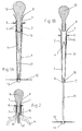
figures 1A et 1B sont des vues de côté, en coupe, d'un mode de réalisation préféré d'un dispositif agencé conformément à l'invention, montré dans respectivement deux positions fonctionnelles différentes ; - la
figure 2 est une vue partielle de côté, en coupe, d'une variante de réalisation du dispositif desfigures 1A et 1B ; - les
figures 3A et 3B sont des vues montrant l'extraction du dispositif desfigures 1A et 1B hors du col d'un récipient tel qu'une bouteille et respectivement son introduction dans le col d'un tel récipient ; - la
figure 4 montre le dispositif desfigures 1A et 1B en place dans une bouteille partiellement remplie ; et - la
figure 5 montre le versement d'un liquide par inclinaison d'une bouteille partiellement remplie et équipée du dispositif desfigures 1A et 1B .
- the
Figures 1A and 1B are side views, in section, of a preferred embodiment of a device arranged in accordance with the invention, shown respectively in two different functional positions; - the
figure 2 is a partial side view, in section, of an alternative embodiment of the device of theFigures 1A and 1B ; - the
Figures 3A and 3B are views showing the extraction of the device fromFigures 1A and 1B out of the neck of a container such as a bottle and respectively its introduction into the neck of such a container; - the
figure 4 shows the deviceFigures 1A and 1B in place in a partially filled bottle; and - the
figure 5 shows the pouring of a liquid by inclination of a partially filled bottle and equipped with the device ofFigures 1A and 1B .
Dans la description qui suit, les termes supérieur et inférieur ainsi que les termes au-dessus et en dessous doivent se comprendre en référence à la situation approximativement verticale occupée par le dispositif mis en place dans un récipient à col tel qu'une bouteille reposant sur un support plan.In the description which follows, the terms upper and lower as well as the terms above and below must be understood in reference to the approximately vertical situation occupied by the device set up in a container neck such as a bottle based on a flat support.
On se réfère tout d'abord aux
Le corps 1 tubulaire est muni d'une ouverture 7 axiale supérieure et l'extrémité du corps 1 tubulaire est agencée sous forme évasée pour constituer un bord verseur 8.The
Un organe mobile d'obturation 10 (en pratique par exemple un bouchon amovible comme représenté) est propre à obturer de façon étanche l'ouverture 4 axiale supérieure dudit corps tubulaire.A movable shutter member 10 (in practice for example a removable plug as shown) is adapted to seal the upper
Une tige 11 de guidage est supportée sensiblement axialement par l'extrémité inférieure du corps 1 tubulaire et s'étend dans le prolongement dudit corps 1 tubulaire. Un élément 12 discoïdal mince en forme générale de membrane est percé sensiblement centralement et est monté à libre coulissement sur ladite tige 11 de guidage. L'élément 12 discoïdal est constitué en un matériau élastiquement déformable ayant une densité moindre que celle du liquide, de manière à pouvoir flotter à la surface libre de celui-ci. Le bout inférieur de la tige 11 de guidage est conformé en tête 13 élargie propre à retenir l'élément 12 discoïdal.A
Lors de l'introduction du dispositif dans le récipient à travers le col 3, l'élément 12 discoïdal doit être ramassé sur lui-même, puis doit se déplier en travers du corps 20 du récipient. A ce moment, il faut donc que le déploiement de l'élément 12 discoïdal ne soit pas gêné par la paroi de l'épaule du récipient. En particulier, pour autoriser une introduction comme illustré à la
Par ailleurs, la manière la plus simple d'introduire le dispositif à l'intérieur d'un récipient 4 est celle qui est illustrée à la
Le corps 1 tubulaire est ouvert dans sa partie inférieure en dessous de la portion 2 de montage. Dans l'exemple de réalisation illustré aux
Dans le mode de réalisation préféré représenté aux
La tige 11 de guidage est équipée, à son extrémité supérieure qui reste intérieure au corps 1 tubulaire, d'une tête 16 élargie de retenue.The
Bien entendu, les dispositions exposées ci-dessus ne sont pas les seules envisageables et d'autres solutions peuvent être adoptées, en tant que de besoin, par l'homme du métier. A titre d'exemple, la
Comme montré à la
L'élément discoïdal 12 peut être réalisé en tout matériau élastiquement déformable inerte vis-à-vis du liquide contenu dans le récipient 4. Il est réalisé sous forme d'une membrane souple qui peut être plus épaisse et/ou renforcée vers son centre et amincie vers sa périphérie. L'élément 12 discoïdal est ainsi apte à se déformer notablement, en se refermant en parapluie autour de la tige 11 lors de l'introduction du dispositif dans le col 3 d'un récipient 4 comme montré à la
La
On peut également noter que le dispositif conforme à l'invention qui vient d'être décrit peut être équipé d'un filtre amovible (non représenté) propre à retenir des particules présentes dans le liquide (dépôt dans un vin par exemple).It may also be noted that the device according to the invention which has just been described may be equipped with a removable filter (not shown) suitable for retaining particles present in the liquid (deposit in a wine for example).
Claims (10)
- Protection device for the protection of a liquid contained in a receptacle (4) with a neck (3), from the atmosphere surrounding it, with the said device comprising a discoidal (12) element that consists of an elastically deformable material, and where this material has a lower density than that of the liquid and is dimensioned in correspondence with the interior transverse dimension of the said receptacle (4) and means of support that is designed to support the said discoidal element (12) inside receptacle (14), and distinguished by the fact that the means of support consist of:- a tubular body (1) with an upper assembly part (2) that is suitable for friction-fitting in the neck (3) of said receptacle (4), with the said tubular body (1) equipped with an upper axial opening (8) and open at part (21) located under the said upper portion (2) of the assembly,- a moveable plugging element (10) designed to plug the said upper axial opening (8) of the said tubular body (1),- a guide shaft (11) that is supported in a substantially axial manner by the lower end of the said tubular body (1),- the abovementioned discoidal element (12) is perforated in a substantially central manner and is mounted so that it slides freely on the said guide shaft (11), because of which the discoidal element (12) can rest on the free surface of the liquid and follow the variations of the level of the liquid in the receptacle (4) and the device, when the plugging element (10) has been removed, allows the liquid to be poured out of the inclined receptacle (4).
- Device according to claim 1, distinguished by the fact that part (21) of tubular body (1) which is sub-jacent to the said upper part (2) of the assembly has a length that is such that the discoidal element (12), which is captured around the tubular body (1) while the device is being introduced through the neck (3) of a receptacle (4), can be deployed freely inside the body (20) of the receptacle once the device is in position in the receptacle.
- Device according to claim 1 or 2, distinguished by the fact that part (21) of tubular body (1), which is sub-jacent to the said upper part (2) of the assembly, has a diameter that is substantially smaller than that of the said upper part (2) of the assembly, because of which an annular space is left free between the tubular body (1) and the wall of the neck (3) of the receptacle while the device is being introduced through the neck (3) of a receptacle (4), and where this annular space is designed to accommodate the discoidal element (12), which is captured around tubular body (1).
- Device according to claim 3, distinguished by the fact that part (21) of tubular body (1), which is sub-jacent to the said upper part (2) of the assembly, is substantially tapered with the taper pointing towards the lower end of tubular body (1).
- Device according to any one of claims 1 to 4, distinguished by the fact that the upper assembly part (2) of tubular body (1) that is designed to fit impermeably with the neck (3) of receptacle (4).
- Device according to claim 5, distinguished by the fact that the tubular body (1) comprises at least one external peripheral bead (5) that projects radially.
- Device according to any one of claims 1 to 6, distinguished by the fact that the tubular body (1) is closed at its lower end by a bottom (14) and by the fact that it comprises at least one open lumen (9) in the lateral wall of tubular body (1).
- Device according to claim 7, distinguished by the fact that the tubular body (1) comprises multiple through-lumens (9) that are distributed evenly over its perimeter.
- Device according to any one of claims 1 to 8, distinguished by the fact that the guide shaft (11) is supported by the end of the tubular body (1) so that it slides, because of which the guide shaft can occupy a non-functional position in which it disappears telescopically, at least in part, inside tubular body (1).
- Device according to claim 8, distinguished by the fact that the bottom (14) of tubular body (1) is equipped with a through-passage (15) and by the fact that the guide shaft (11) is engaged through the said passage (15).
Applications Claiming Priority (2)
| Application Number | Priority Date | Filing Date | Title |
|---|---|---|---|
| FR0513408A FR2895376B1 (en) | 2005-12-28 | 2005-12-28 | PROTECTIVE DEVICE, ABOVE THE ATMOSPHERE THAT OVERCOMES IT, OF A LIQUID IN A COLD CONTAINER. |
| PCT/IB2006/003773 WO2007074382A2 (en) | 2005-12-28 | 2006-12-27 | Device for protecting a liquid in a necked container from the overlying atmosphere |
Publications (2)
| Publication Number | Publication Date |
|---|---|
| EP1973807A2 EP1973807A2 (en) | 2008-10-01 |
| EP1973807B1 true EP1973807B1 (en) | 2009-12-02 |
Family
ID=36974701
Family Applications (1)
| Application Number | Title | Priority Date | Filing Date |
|---|---|---|---|
| EP06842279A Not-in-force EP1973807B1 (en) | 2005-12-28 | 2006-12-27 | Device for protecting a liquid in a necked container from the overlying atmosphere |
Country Status (5)
| Country | Link |
|---|---|
| EP (1) | EP1973807B1 (en) |
| AT (1) | ATE450454T1 (en) |
| DE (1) | DE602006010908D1 (en) |
| FR (1) | FR2895376B1 (en) |
| WO (1) | WO2007074382A2 (en) |
Families Citing this family (1)
| Publication number | Priority date | Publication date | Assignee | Title |
|---|---|---|---|---|
| SE535072C2 (en) * | 2010-08-30 | 2012-04-03 | Konsolvia Ab | Apparatus and method for preserving a product stored in a container provided with an opening |
Family Cites Families (4)
| Publication number | Priority date | Publication date | Assignee | Title |
|---|---|---|---|---|
| BE636572A (en) * | ||||
| GB2237844A (en) * | 1989-11-09 | 1991-05-15 | Enzo Casale | Drawing off liquids from containers |
| DE19858576A1 (en) * | 1998-12-18 | 2000-06-21 | Albert Haefner | Container for storage of liquids or solids, with sealing disk which can be lowered by rod onto surface of liquid or solid |
| US20030102311A1 (en) * | 2001-12-05 | 2003-06-05 | Brady James R. | Method and or apparatus to reduce the oxidation of liquids including wine, whiskey, oils, paint and others after the orginial sealed bottle or container has been opened for the first time or is placed into original bottlw, can or container when filled for the first time by the manufacture |
-
2005
- 2005-12-28 FR FR0513408A patent/FR2895376B1/en not_active Expired - Fee Related
-
2006
- 2006-12-27 WO PCT/IB2006/003773 patent/WO2007074382A2/en active Application Filing
- 2006-12-27 DE DE602006010908T patent/DE602006010908D1/en not_active Expired - Fee Related
- 2006-12-27 EP EP06842279A patent/EP1973807B1/en not_active Not-in-force
- 2006-12-27 AT AT06842279T patent/ATE450454T1/en not_active IP Right Cessation
Also Published As
| Publication number | Publication date |
|---|---|
| FR2895376B1 (en) | 2008-02-01 |
| WO2007074382A2 (en) | 2007-07-05 |
| EP1973807A2 (en) | 2008-10-01 |
| FR2895376A1 (en) | 2007-06-29 |
| DE602006010908D1 (en) | 2010-01-14 |
| WO2007074382A3 (en) | 2007-10-04 |
| ATE450454T1 (en) | 2009-12-15 |
Similar Documents
| Publication | Publication Date | Title |
|---|---|---|
| EP2822873B1 (en) | Insert for fixing a bag within a bottle | |
| FR2895374A1 (en) | Sleeve for valve of aerosol spray can has inner sections which fit against valve, outer section at base of sleeve having deformable part which can be deformed both axially and radially | |
| EP1044893A1 (en) | Device for the extemporaneous mixture of at least two products, of which one is a powder | |
| EP3094418B1 (en) | Fluid tank and dispenser | |
| EP2718197B1 (en) | Stopping device and container comprising such a device | |
| FR2502591A1 (en) | CONNECTION ASSEMBLY FOR TWO-COMPONENT SYSTEMS | |
| FR3046142A1 (en) | CONTAINER FOR STORAGE AND INDIVIDUAL DISCHARGE OF CAPSULES | |
| EP0626321B1 (en) | Liquid dispensing device without dip tube | |
| EP1973807B1 (en) | Device for protecting a liquid in a necked container from the overlying atmosphere | |
| EP2348812B1 (en) | Autonomous anti-spill carrier for a bouquet of flowers | |
| FR2924099A1 (en) | Liquid or powdery fluid product e.g. pharmaceutical product, diffusing closure, has orifice arranged opposite to inner seating face of ring and separated below face in top and bottom positions of tubular hollow part of slide, respectively | |
| WO2011058272A1 (en) | Container for fluid comprising a bag for containing said fluid and related barrel | |
| WO2015091597A1 (en) | Device for plugging a container that has a neck | |
| FR2677106A1 (en) | Gas cylinder (bottle) | |
| EP2366635B1 (en) | Lid assembly and box including such a lid assembly | |
| EP2146923B1 (en) | Closure cover for container designed for storing carbonate liquids, and container provided with such a cover | |
| EP1114594B1 (en) | Product dispenser arranged to enable a user to observe the colour of the product | |
| FR2807012A1 (en) | Pourer plug, for bottle, comprises hollow body whose lower part fits in bottle neck, and upper part carrying pourer orifice has widened chamber which discharges through neck adjacent to rim | |
| EP4304949A1 (en) | Opening device with an integrated straw, and method for manufacturing the device | |
| WO2009056770A1 (en) | Metering device adaptable to a container | |
| CA1050487A (en) | Fluid pressure sensitive capsule for beverage distribution_ | |
| BE892624A (en) | CONNECTION ASSEMBLY FOR TWO-COMPONENT SYSTEMS | |
| EP4029416A1 (en) | Removable infuser for tea or another plant for infusion capable of and intended for equipping an infuser container and infuser container provided with an infuser | |
| FR2950331A1 (en) | Beverage i.e. wine, dispenser, has receptacle rotatably mounted around central axis, so that dispensing unit is displaceable angularly, where receptacle is supported on support face that forms slope inclined downward toward unit | |
| FR2627464A1 (en) | DEVICE FOR THE INSTANT REALIZATION OF A QUALITY INFUSED COFFEE |
Legal Events
| Date | Code | Title | Description |
|---|---|---|---|
| PUAI | Public reference made under article 153(3) epc to a published international application that has entered the european phase |
Free format text: ORIGINAL CODE: 0009012 |
|
| 17P | Request for examination filed |
Effective date: 20080513 |
|
| AK | Designated contracting states |
Kind code of ref document: A2 Designated state(s): AT BE BG CH CY CZ DE DK EE ES FI FR GB GR HU IE IS IT LI LT LU LV MC NL PL PT RO SE SI SK TR |
|
| GRAP | Despatch of communication of intention to grant a patent |
Free format text: ORIGINAL CODE: EPIDOSNIGR1 |
|
| GRAS | Grant fee paid |
Free format text: ORIGINAL CODE: EPIDOSNIGR3 |
|
| DAX | Request for extension of the european patent (deleted) | ||
| GRAA | (expected) grant |
Free format text: ORIGINAL CODE: 0009210 |
|
| AK | Designated contracting states |
Kind code of ref document: B1 Designated state(s): AT BE BG CH CY CZ DE DK EE ES FI FR GB GR HU IE IS IT LI LT LU LV MC NL PL PT RO SE SI SK TR |
|
| REG | Reference to a national code |
Ref country code: GB Ref legal event code: FG4D Free format text: NOT ENGLISH |
|
| REG | Reference to a national code |
Ref country code: CH Ref legal event code: EP |
|
| REG | Reference to a national code |
Ref country code: IE Ref legal event code: FG4D |
|
| REF | Corresponds to: |
Ref document number: 602006010908 Country of ref document: DE Date of ref document: 20100114 Kind code of ref document: P |
|
| REG | Reference to a national code |
Ref country code: NL Ref legal event code: VDEP Effective date: 20091202 |
|
| PG25 | Lapsed in a contracting state [announced via postgrant information from national office to epo] |
Ref country code: SE Free format text: LAPSE BECAUSE OF FAILURE TO SUBMIT A TRANSLATION OF THE DESCRIPTION OR TO PAY THE FEE WITHIN THE PRESCRIBED TIME-LIMIT Effective date: 20091202 Ref country code: LT Free format text: LAPSE BECAUSE OF FAILURE TO SUBMIT A TRANSLATION OF THE DESCRIPTION OR TO PAY THE FEE WITHIN THE PRESCRIBED TIME-LIMIT Effective date: 20091202 Ref country code: FI Free format text: LAPSE BECAUSE OF FAILURE TO SUBMIT A TRANSLATION OF THE DESCRIPTION OR TO PAY THE FEE WITHIN THE PRESCRIBED TIME-LIMIT Effective date: 20091202 |
|
| LTIE | Lt: invalidation of european patent or patent extension |
Effective date: 20091202 |
|
| PG25 | Lapsed in a contracting state [announced via postgrant information from national office to epo] |
Ref country code: LV Free format text: LAPSE BECAUSE OF FAILURE TO SUBMIT A TRANSLATION OF THE DESCRIPTION OR TO PAY THE FEE WITHIN THE PRESCRIBED TIME-LIMIT Effective date: 20091202 Ref country code: CY Free format text: LAPSE BECAUSE OF FAILURE TO SUBMIT A TRANSLATION OF THE DESCRIPTION OR TO PAY THE FEE WITHIN THE PRESCRIBED TIME-LIMIT Effective date: 20091202 Ref country code: PL Free format text: LAPSE BECAUSE OF FAILURE TO SUBMIT A TRANSLATION OF THE DESCRIPTION OR TO PAY THE FEE WITHIN THE PRESCRIBED TIME-LIMIT Effective date: 20091202 Ref country code: SI Free format text: LAPSE BECAUSE OF FAILURE TO SUBMIT A TRANSLATION OF THE DESCRIPTION OR TO PAY THE FEE WITHIN THE PRESCRIBED TIME-LIMIT Effective date: 20091202 |
|
| BERE | Be: lapsed |
Owner name: LABBE', JEAN CLAUDE Effective date: 20091231 |
|
| PG25 | Lapsed in a contracting state [announced via postgrant information from national office to epo] |
Ref country code: AT Free format text: LAPSE BECAUSE OF FAILURE TO SUBMIT A TRANSLATION OF THE DESCRIPTION OR TO PAY THE FEE WITHIN THE PRESCRIBED TIME-LIMIT Effective date: 20091202 |
|
| REG | Reference to a national code |
Ref country code: IE Ref legal event code: FD4D |
|
| PG25 | Lapsed in a contracting state [announced via postgrant information from national office to epo] |
Ref country code: MC Free format text: LAPSE BECAUSE OF NON-PAYMENT OF DUE FEES Effective date: 20100701 Ref country code: ES Free format text: LAPSE BECAUSE OF FAILURE TO SUBMIT A TRANSLATION OF THE DESCRIPTION OR TO PAY THE FEE WITHIN THE PRESCRIBED TIME-LIMIT Effective date: 20100313 Ref country code: IS Free format text: LAPSE BECAUSE OF FAILURE TO SUBMIT A TRANSLATION OF THE DESCRIPTION OR TO PAY THE FEE WITHIN THE PRESCRIBED TIME-LIMIT Effective date: 20100402 Ref country code: PT Free format text: LAPSE BECAUSE OF FAILURE TO SUBMIT A TRANSLATION OF THE DESCRIPTION OR TO PAY THE FEE WITHIN THE PRESCRIBED TIME-LIMIT Effective date: 20100402 Ref country code: IE Free format text: LAPSE BECAUSE OF FAILURE TO SUBMIT A TRANSLATION OF THE DESCRIPTION OR TO PAY THE FEE WITHIN THE PRESCRIBED TIME-LIMIT Effective date: 20091202 Ref country code: EE Free format text: LAPSE BECAUSE OF FAILURE TO SUBMIT A TRANSLATION OF THE DESCRIPTION OR TO PAY THE FEE WITHIN THE PRESCRIBED TIME-LIMIT Effective date: 20091202 Ref country code: BG Free format text: LAPSE BECAUSE OF FAILURE TO SUBMIT A TRANSLATION OF THE DESCRIPTION OR TO PAY THE FEE WITHIN THE PRESCRIBED TIME-LIMIT Effective date: 20100302 Ref country code: NL Free format text: LAPSE BECAUSE OF FAILURE TO SUBMIT A TRANSLATION OF THE DESCRIPTION OR TO PAY THE FEE WITHIN THE PRESCRIBED TIME-LIMIT Effective date: 20091202 Ref country code: RO Free format text: LAPSE BECAUSE OF FAILURE TO SUBMIT A TRANSLATION OF THE DESCRIPTION OR TO PAY THE FEE WITHIN THE PRESCRIBED TIME-LIMIT Effective date: 20091202 |
|
| PG25 | Lapsed in a contracting state [announced via postgrant information from national office to epo] |
Ref country code: SK Free format text: LAPSE BECAUSE OF FAILURE TO SUBMIT A TRANSLATION OF THE DESCRIPTION OR TO PAY THE FEE WITHIN THE PRESCRIBED TIME-LIMIT Effective date: 20091202 Ref country code: CZ Free format text: LAPSE BECAUSE OF FAILURE TO SUBMIT A TRANSLATION OF THE DESCRIPTION OR TO PAY THE FEE WITHIN THE PRESCRIBED TIME-LIMIT Effective date: 20091202 |
|
| PLBE | No opposition filed within time limit |
Free format text: ORIGINAL CODE: 0009261 |
|
| STAA | Information on the status of an ep patent application or granted ep patent |
Free format text: STATUS: NO OPPOSITION FILED WITHIN TIME LIMIT |
|
| PG25 | Lapsed in a contracting state [announced via postgrant information from national office to epo] |
Ref country code: BE Free format text: LAPSE BECAUSE OF NON-PAYMENT OF DUE FEES Effective date: 20091231 Ref country code: GR Free format text: LAPSE BECAUSE OF FAILURE TO SUBMIT A TRANSLATION OF THE DESCRIPTION OR TO PAY THE FEE WITHIN THE PRESCRIBED TIME-LIMIT Effective date: 20100303 |
|
| 26N | No opposition filed |
Effective date: 20100903 |
|
| PG25 | Lapsed in a contracting state [announced via postgrant information from national office to epo] |
Ref country code: DE Free format text: LAPSE BECAUSE OF NON-PAYMENT OF DUE FEES Effective date: 20100701 |
|
| PG25 | Lapsed in a contracting state [announced via postgrant information from national office to epo] |
Ref country code: DK Free format text: LAPSE BECAUSE OF FAILURE TO SUBMIT A TRANSLATION OF THE DESCRIPTION OR TO PAY THE FEE WITHIN THE PRESCRIBED TIME-LIMIT Effective date: 20091202 |
|
| PG25 | Lapsed in a contracting state [announced via postgrant information from national office to epo] |
Ref country code: IT Free format text: LAPSE BECAUSE OF FAILURE TO SUBMIT A TRANSLATION OF THE DESCRIPTION OR TO PAY THE FEE WITHIN THE PRESCRIBED TIME-LIMIT Effective date: 20091202 |
|
| REG | Reference to a national code |
Ref country code: FR Ref legal event code: ST Effective date: 20110228 |
|
| PG25 | Lapsed in a contracting state [announced via postgrant information from national office to epo] |
Ref country code: LU Free format text: LAPSE BECAUSE OF NON-PAYMENT OF DUE FEES Effective date: 20091227 |
|
| PG25 | Lapsed in a contracting state [announced via postgrant information from national office to epo] |
Ref country code: FR Free format text: LAPSE BECAUSE OF NON-PAYMENT OF DUE FEES Effective date: 20100202 |
|
| PG25 | Lapsed in a contracting state [announced via postgrant information from national office to epo] |
Ref country code: HU Free format text: LAPSE BECAUSE OF FAILURE TO SUBMIT A TRANSLATION OF THE DESCRIPTION OR TO PAY THE FEE WITHIN THE PRESCRIBED TIME-LIMIT Effective date: 20100603 |
|
| REG | Reference to a national code |
Ref country code: CH Ref legal event code: PL |
|
| GBPC | Gb: european patent ceased through non-payment of renewal fee |
Effective date: 20101227 |
|
| PG25 | Lapsed in a contracting state [announced via postgrant information from national office to epo] |
Ref country code: TR Free format text: LAPSE BECAUSE OF FAILURE TO SUBMIT A TRANSLATION OF THE DESCRIPTION OR TO PAY THE FEE WITHIN THE PRESCRIBED TIME-LIMIT Effective date: 20091202 |
|
| PG25 | Lapsed in a contracting state [announced via postgrant information from national office to epo] |
Ref country code: CH Free format text: LAPSE BECAUSE OF NON-PAYMENT OF DUE FEES Effective date: 20101231 Ref country code: LI Free format text: LAPSE BECAUSE OF NON-PAYMENT OF DUE FEES Effective date: 20101231 |
|
| PG25 | Lapsed in a contracting state [announced via postgrant information from national office to epo] |
Ref country code: GB Free format text: LAPSE BECAUSE OF NON-PAYMENT OF DUE FEES Effective date: 20101227 |