EP1973680B1 - Three-dimensional complex coil - Google Patents
Three-dimensional complex coil Download PDFInfo
- Publication number
- EP1973680B1 EP1973680B1 EP06848957.4A EP06848957A EP1973680B1 EP 1973680 B1 EP1973680 B1 EP 1973680B1 EP 06848957 A EP06848957 A EP 06848957A EP 1973680 B1 EP1973680 B1 EP 1973680B1
- Authority
- EP
- European Patent Office
- Prior art keywords
- loop
- loops
- pattern
- complex coil
- complex
- Prior art date
- Legal status (The legal status is an assumption and is not a legal conclusion. Google has not performed a legal analysis and makes no representation as to the accuracy of the status listed.)
- Active
Links
- 238000000034 method Methods 0.000 claims description 17
- 238000004519 manufacturing process Methods 0.000 claims description 3
- BASFCYQUMIYNBI-UHFFFAOYSA-N platinum Chemical compound [Pt] BASFCYQUMIYNBI-UHFFFAOYSA-N 0.000 description 13
- 238000004804 winding Methods 0.000 description 12
- 239000000463 material Substances 0.000 description 6
- 229910052697 platinum Inorganic materials 0.000 description 5
- 206010002329 Aneurysm Diseases 0.000 description 4
- 239000000017 hydrogel Substances 0.000 description 4
- 229910052721 tungsten Inorganic materials 0.000 description 4
- 229920004934 Dacron® Polymers 0.000 description 2
- 208000005189 Embolism Diseases 0.000 description 2
- 201000008450 Intracranial aneurysm Diseases 0.000 description 2
- 229920000954 Polyglycolide Polymers 0.000 description 2
- 229910001260 Pt alloy Inorganic materials 0.000 description 2
- 208000007536 Thrombosis Diseases 0.000 description 2
- 229910001080 W alloy Inorganic materials 0.000 description 2
- 238000000137 annealing Methods 0.000 description 2
- 239000000560 biocompatible material Substances 0.000 description 2
- 229920002988 biodegradable polymer Polymers 0.000 description 2
- 239000004621 biodegradable polymer Substances 0.000 description 2
- 230000015572 biosynthetic process Effects 0.000 description 2
- 239000008280 blood Substances 0.000 description 2
- 210000004369 blood Anatomy 0.000 description 2
- 239000000919 ceramic Substances 0.000 description 2
- 230000008878 coupling Effects 0.000 description 2
- 238000010168 coupling process Methods 0.000 description 2
- 238000005859 coupling reaction Methods 0.000 description 2
- 239000000835 fiber Substances 0.000 description 2
- 230000004941 influx Effects 0.000 description 2
- 230000007246 mechanism Effects 0.000 description 2
- 229910001000 nickel titanium Inorganic materials 0.000 description 2
- HLXZNVUGXRDIFK-UHFFFAOYSA-N nickel titanium Chemical compound [Ti].[Ti].[Ti].[Ti].[Ti].[Ti].[Ti].[Ti].[Ti].[Ti].[Ti].[Ni].[Ni].[Ni].[Ni].[Ni].[Ni].[Ni].[Ni].[Ni].[Ni].[Ni].[Ni].[Ni].[Ni] HLXZNVUGXRDIFK-UHFFFAOYSA-N 0.000 description 2
- 229920001778 nylon Polymers 0.000 description 2
- 229920000747 poly(lactic acid) Polymers 0.000 description 2
- 239000005020 polyethylene terephthalate Substances 0.000 description 2
- 239000004633 polyglycolic acid Substances 0.000 description 2
- 239000004626 polylactic acid Substances 0.000 description 2
- 229910001220 stainless steel Inorganic materials 0.000 description 2
- 239000010935 stainless steel Substances 0.000 description 2
- 229910052715 tantalum Inorganic materials 0.000 description 2
- GUVRBAGPIYLISA-UHFFFAOYSA-N tantalum atom Chemical compound [Ta] GUVRBAGPIYLISA-UHFFFAOYSA-N 0.000 description 2
- WFKWXMTUELFFGS-UHFFFAOYSA-N tungsten Chemical compound [W] WFKWXMTUELFFGS-UHFFFAOYSA-N 0.000 description 2
- 239000010937 tungsten Substances 0.000 description 2
- KHOITXIGCFIULA-UHFFFAOYSA-N Alophen Chemical compound C1=CC(OC(=O)C)=CC=C1C(C=1N=CC=CC=1)C1=CC=C(OC(C)=O)C=C1 KHOITXIGCFIULA-UHFFFAOYSA-N 0.000 description 1
- 230000008901 benefit Effects 0.000 description 1
- 210000004204 blood vessel Anatomy 0.000 description 1
- 238000010276 construction Methods 0.000 description 1
- 230000000694 effects Effects 0.000 description 1
- 230000006870 function Effects 0.000 description 1
- 239000007943 implant Substances 0.000 description 1
- 230000003902 lesion Effects 0.000 description 1
- 229910052751 metal Inorganic materials 0.000 description 1
- 239000002184 metal Substances 0.000 description 1
- 238000012986 modification Methods 0.000 description 1
- 230000004048 modification Effects 0.000 description 1
- 235000020004 porter Nutrition 0.000 description 1
- 210000005166 vasculature Anatomy 0.000 description 1
Images


Classifications
-
- B—PERFORMING OPERATIONS; TRANSPORTING
- B21—MECHANICAL METAL-WORKING WITHOUT ESSENTIALLY REMOVING MATERIAL; PUNCHING METAL
- B21F—WORKING OR PROCESSING OF METAL WIRE
- B21F45/00—Wire-working in the manufacture of other particular articles
- B21F45/008—Wire-working in the manufacture of other particular articles of medical instruments, e.g. stents, corneal rings
-
- A—HUMAN NECESSITIES
- A61—MEDICAL OR VETERINARY SCIENCE; HYGIENE
- A61B—DIAGNOSIS; SURGERY; IDENTIFICATION
- A61B17/00—Surgical instruments, devices or methods, e.g. tourniquets
- A61B17/12—Surgical instruments, devices or methods, e.g. tourniquets for ligaturing or otherwise compressing tubular parts of the body, e.g. blood vessels, umbilical cord
- A61B17/12022—Occluding by internal devices, e.g. balloons or releasable wires
- A61B17/12131—Occluding by internal devices, e.g. balloons or releasable wires characterised by the type of occluding device
- A61B17/1214—Coils or wires
- A61B17/12145—Coils or wires having a pre-set deployed three-dimensional shape
-
- A—HUMAN NECESSITIES
- A61—MEDICAL OR VETERINARY SCIENCE; HYGIENE
- A61B—DIAGNOSIS; SURGERY; IDENTIFICATION
- A61B17/00—Surgical instruments, devices or methods, e.g. tourniquets
- A61B17/12—Surgical instruments, devices or methods, e.g. tourniquets for ligaturing or otherwise compressing tubular parts of the body, e.g. blood vessels, umbilical cord
- A61B17/12022—Occluding by internal devices, e.g. balloons or releasable wires
- A61B17/12131—Occluding by internal devices, e.g. balloons or releasable wires characterised by the type of occluding device
- A61B17/1214—Coils or wires
- A61B17/1215—Coils or wires comprising additional materials, e.g. thrombogenic, having filaments, having fibers, being coated
-
- A—HUMAN NECESSITIES
- A61—MEDICAL OR VETERINARY SCIENCE; HYGIENE
- A61B—DIAGNOSIS; SURGERY; IDENTIFICATION
- A61B17/00—Surgical instruments, devices or methods, e.g. tourniquets
- A61B17/12—Surgical instruments, devices or methods, e.g. tourniquets for ligaturing or otherwise compressing tubular parts of the body, e.g. blood vessels, umbilical cord
- A61B17/12022—Occluding by internal devices, e.g. balloons or releasable wires
- A61B17/12131—Occluding by internal devices, e.g. balloons or releasable wires characterised by the type of occluding device
- A61B17/1214—Coils or wires
- A61B17/12154—Coils or wires having stretch limiting means
-
- A—HUMAN NECESSITIES
- A61—MEDICAL OR VETERINARY SCIENCE; HYGIENE
- A61B—DIAGNOSIS; SURGERY; IDENTIFICATION
- A61B17/00—Surgical instruments, devices or methods, e.g. tourniquets
- A61B17/12—Surgical instruments, devices or methods, e.g. tourniquets for ligaturing or otherwise compressing tubular parts of the body, e.g. blood vessels, umbilical cord
- A61B17/12022—Occluding by internal devices, e.g. balloons or releasable wires
- A61B17/12131—Occluding by internal devices, e.g. balloons or releasable wires characterised by the type of occluding device
- A61B17/12181—Occluding by internal devices, e.g. balloons or releasable wires characterised by the type of occluding device formed by fluidized, gelatinous or cellular remodelable materials, e.g. embolic liquids, foams or extracellular matrices
- A61B17/1219—Occluding by internal devices, e.g. balloons or releasable wires characterised by the type of occluding device formed by fluidized, gelatinous or cellular remodelable materials, e.g. embolic liquids, foams or extracellular matrices expandable in contact with liquids
-
- B—PERFORMING OPERATIONS; TRANSPORTING
- B21—MECHANICAL METAL-WORKING WITHOUT ESSENTIALLY REMOVING MATERIAL; PUNCHING METAL
- B21F—WORKING OR PROCESSING OF METAL WIRE
- B21F45/00—Wire-working in the manufacture of other particular articles
-
- A—HUMAN NECESSITIES
- A61—MEDICAL OR VETERINARY SCIENCE; HYGIENE
- A61B—DIAGNOSIS; SURGERY; IDENTIFICATION
- A61B17/00—Surgical instruments, devices or methods, e.g. tourniquets
- A61B2017/00526—Methods of manufacturing
-
- A—HUMAN NECESSITIES
- A61—MEDICAL OR VETERINARY SCIENCE; HYGIENE
- A61B—DIAGNOSIS; SURGERY; IDENTIFICATION
- A61B17/00—Surgical instruments, devices or methods, e.g. tourniquets
- A61B2017/00831—Material properties
- A61B2017/00867—Material properties shape memory effect
Definitions
- the prior art contemplates a number of methods and devices for treating a body aneurysm using three-dimensional (3-D) shaped coils, sometimes referred to as "complex" coils.
- 3-D three-dimensional
- Phelps 5,382,259 and Ritchart 4,994,069 show other 3-D coil designs.
- Teoh 6,635,069 teaches a series of nonoverlapping loops.
- Wallace 6,860,893 shows complex coils.
- Ferrera 6,638,291 shows a device similar to Teoh's and Wallace's except that a J-shaped proximal segment extends away from the complex portion of the device.
- WO0074577 discloses a medical device for forming an embolism within the vasculature of a patient.
- US5639277 discloses a surgical device that is for forming a vasoocclusion or embolism. Typically, it is a helically wound coil in which the helix is wound in such a way as to have multiple axially offset, longitudinal or focal axes.
- US20020107534 discloses a vaso-occlusive device that includes a microcoil formed into a minimum energy state secondary configuration comprising a plurality of curved segments, each defining a discrete axis, whereby the device, in its minimum energy state configuration, defines multiple axes.
- WO9409705 relates to a vasoocclusion coil which may be segmented.
- US6322576 discloses device discloses a vaso-occlusive device with a complex, three-dimensional structure in a relaxed configuration that may be used in the approximate shape of an anatomical cavity.
- embodiments of the invention at least one embodiment of which includes a toroid-shaped device wound around a fixture such that portions of the device's length meet or overlap in the center of the toroid. This allows the outer portion of the device to form a scaffold while the interior portion of the device provides occlusion to prevent the influx of blood and promote thrombus formation.
- One embodiment includes a strand of material that self-forms into a toroid-shaped series of loops and is designed to provide a stable structure within the body cavity, allowing for occlusion of the cavity and serving as a framework to hold additional treatment devices.
- Another embodiment of the present invention provides a strand of material that self-forms into a cruciform series of loops and is designed to provide a stable structure within the body cavity, allowing for occlusion of the cavity and serving as a framework to hold additional treatment devices.
- the embodiment of invention includes tools and methods of manufacture to make the aforementioned embodiments of the invention.
- an embodiment in yet another aspect of the embodiments of present invention, includes a cruciform device wound around a fixture comprising at least two parallel pins disposed at an angle to at least one additional pin.
- This construction allows the outer portion of the device to form a scaffold while the interior portion of the device provides occlusion to prevent the influx of blood and promote thrombus formation.
- This embodiment also advantageously resists rotating or tumbling during deployment.
- a coil or complex coil 10 is described that is shaped using a toroid-shaped fixture 12.
- the coil 10 has been wrapped around the fixture 12 four times in Figure 1 such that four loops 14 are formed, each loop being positioned approximately 90 degrees from the adjacent loops. Wrapping the coil 10 around the fixture 12 causes the coil 10 to form into a complex shape when deployed into a body cavity such as a blood vessel or aneurysm.
- the device may be made from a length of wire that has been helically wound to form an elongate coil wire. Alternatively, the wire may be braided or knitted by methods known in the art to form a secondary shape.
- the wire is preferably a memory metal, such as Nitinol, but may be platinum, tantalum, tungsten, stainless steel, or other biocompatible material.
- Other materials such as Dacron or Nylon fibers, biodegradable polymers such as polylactic or polyglycolic acid, and expansible or non-expansible hydrogel materials may be placed inside or outside the coil or braid structure to enhance the performance of the device.
- each of the loops 14a-d is roughly contained within respective planes 16a-d.
- the planes intersect with each other at approximately a common intersection axis 18 near the center of the complex coil 10.
- any loops formed around the toroid fixture 12 will only approximately be contained within such planes and the degree to which they are contained within these planes is only a function of how they are wound around the toroid and has little or no effect on their performance.
- any number of loops may be used in forming a complex coil of the present invention.
- a complex coil 20 is formed by wrapping eight loops 22 around the toroid-shaped fixture 12. The loops 22 are relatively evenly spaced around the toroid 12 but may be spaced in any number of configurations. The result is the eight-looped complex coil 20 shown in Figure 4 .
- Figures 5 and 6 show complex coils 30 being formed around a toroid fixture 12 using 16 loops 32.
- the loops 32 are grouped in sets of two such that only eight distinct loops appear.
- One example used to treat conditions includes a platinum/tungsten alloy complex coil (92% Pt, 8% W available from Sigmund Cohn Mount Vernon, NY) with a diameter in the range of about .125 mm to about .625 mm and a length of about 5 mm to about 1000 mm.
- the complex coil is formed around a ceramic or metallic toroid-shaped fixture similar to the fixtures 12 shown in Figs. 1 , 3 , 5, and 6 .
- the winding pattern shown in Figs. 1-6 forms a first loop 14a around the toroid 12, then a second loop 14b approximately 180° around the toroid from the first loop.
- a figure 8 pattern is used to wind the first and second loops.
- a third loop 14c is then formed at an angle around the center of the toroid, typically 5° to 175°, to the second loop.
- a fourth loop 14d is formed using a figure 8 pattern from the third loop 14c. More loops 14 may be added depending on the desired device size.
- the toroid complex coil configuration may be scaled to the size of the treatment site by changing the number of loops.
- very small (0.5-3 mm) lesions may be treated with 2 to 4 loop configurations, medium sized (4-10 mm) with 4-12 loop configurations, large (over 10 mm) with 8-36 loop configurations, and so on.
- the loops can form a closed structure such as an "O" shape (e.g. circle, oval, square, ellipse, star, etc.) or can be open such as a "C" or "U” shape.
- the loops may be of any dimension and are typically scaled to the approximate size of the treatment site.
- the loops may range from 0.5 mm diameter to 50 mm diameter.
- diameter should not be narrowly construed to imply a circular dimension. Rather, “diameter” is used broadly to encompass the approximate size and shape of a loop.
- the fixture and complex coil are heat-set by methods known in the art.
- a typical annealing step for platinum complex coils is approximately 1100° F (593°C) for 5-40 minutes.
- the complex coil will approximately retain the wound shape when substantially unconstrained or in its minimum energy state.
- the complex coil may then be subject to further processing such as forming a tip, adding a coupling mechanism for attachment to a delivery system, placing hydrogel or fibers onto or within the complex coil, placing a stretch resistant member inside or outside the complex coil, etc.
- the complex coil can then be attached to a delivery system, which is well known in the art, such as those disclosed in U.S. Patent Application Serial Number 11/212,830 , entitled Thermal Detachment System for Implantable Devices. Other examples of delivery systems are disclosed in Guglielmi 6,010,498 or Vogel 6,478,773.
- the linear complex coil is fed through a conduit such as a microcatheter by advancing it through the conduit with the delivery pusher. Upon exiting the microcatheter, the complex coil then self-forms into a structure within the treatment site that approximates its annealed shape.
- the fixture 12 used to create the implant is shown as a closed circular toroid.
- other non-circular shapes such as elliptical, square, and star-shaped patterns may be used.
- the toroid does not need to be a closed structure. In fact, it may be easier to wind if a gap is left within the structure so that tension can be kept on the complex coil by hanging a weight.
- the embodiments of the complex coils 40 formed using the fixture 42 in Figures 7-12 may be made from a length of wire that has been helically wound to form a coiled wire.
- the wire may be braided or knitted by methods known in the art to form a secondary shape.
- the wire may be platinum, tantalum, tungsten, stainless steel, Nitinol, or other biocompatible material.
- the complex coil 40 is formed by wrapping a coiled wire around the fixture 42, as shown in Figures 7-8 .
- the fixture 42 is preferably a ceramic or metallic cruciform fixture and includes a plurality of pins 44 arranged at right angles to each other along axes x, y, and z. More specifically, the fixture 42 includes two pins 44x that are parallel to the x-axis, two pins 44y that are parallel to the y-axis, and two pins 44z that are parallel to the z-axis.
- FIG. 9-12 An example of a complex coil 40 that can be made using the fixture 42 of Figures 7-8 is shown in Figures 9-12 .
- the winding pattern in this embodiment shown most clearly in Figures 11-12 , forms a first loop 46a around a first pin 44y 1 , then a second loop 46b around a second pin 44x 1 that is disposed at an angle to the first pin 44y 1 .
- the angle between the loops 46a and 46b is approximately 45°-135°.
- a third loop 46c is then formed in approximately the same plane as the second loop 46b.
- the third loop 46c is formed around pin 44x 2 in a figure 8 pattern with the second loop 46b.
- a fourth loop 46d is then formed at an angle with the third loop 46c.
- the fourth loop 46d is approximately 45°-135° to the third loop and is formed around pin 44y 2 and is also approximately coplanar to the first loop 46a.
- a fifth loop 46e is then formed at an angle to the fourth loop 46d by wrapping the wire around pin 44x 1 spaced apart from loop 46b, also formed around pin 44x 1 .
- a sixth loop 46f lies in approximately the same plane as the fifth loop 46e in a figure 8 pattern with the fifth loop 46e.
- the sixth loop 46f is formed by wrapping the wire around pin 44x 2 spaced apart from loop 46c, which is also formed around pin 44x 2 .
- the fifth loop 46e and the sixth loop 46f are approximately concentric with the second loop 46b and the third loop 46c, respectively.
- the loops can form a closed structure such as an "O" shape (e.g. circle, oval, square, ellipse, star, etc.) or can be open such as a "C" or "U” shape.
- the loops may be of any dimension and are typically scaled to the approximate size of the treatment site. In the previous example, the loops may range from 0.5 mm diameter to 50 mm diameter. In this regard, “diameter” should not be narrowly construed to imply a circular dimension. Rather, diameter is used broadly to encompass the approximate size and shape of a loop.
- the coil 50 shown in Figure 13 has loops 52 that are open and closed.
- the open loops are formed by wrapping a wire around a pin but transitioning to an adjacent pin prior to completing an overlapping loop.
- the complex coil 50 of Figure 13 has six loops 52a-f formed using the fixture 42 of Figures 7 and 8 .
- Loop 52a is a complete loop formed around one of the pins 44y.
- the wire is then wrapped in a figure 8 pattern around two adjacent pins 44x to form open loops 52b and 52c.
- the wire is next wrapped completely around the other y pin, 44y to form complete loop 52d.
- the wire is wrapped in a figure 8 pattern around the two pins 44y on the opposite side of pins 44x to form loops 52e and 52f.
- the loop 52e is open but the loop 52f is closed, being the last loop.
- the fixture 60 in Figures 14-15 also has a plurality of pins 62 but differs from the fixture 42 in Figures 7 and 8 in three substantive ways.
- the pins 62 extend in directions parallel with x- and y-axes, but there are no pins that extend parallel to a z-axis. Rather, rectangular blocks 64 extend along the z-axis.
- the pins 62 extend in directions parallel with x- and y-axes, but there are no pins that extend parallel to a z-axis. Rather, rectangular blocks 64 extend along the z-axis.
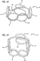
- there are four pins 62y 1-4 each having independent longitudinal axes. Winding using the fixture 60 results in complex coils 70 such as those shown in Figures 16-19 .
- FIGS. 16-19 show the two figure 8 patterns rotated 90 degrees relative to each other.
- the complex coils 70 include fifth and sixth loops, 74e and 74f, which are relatively concentric.
- the fixture and complex coil are heat-set by methods known in the art.
- a typical annealing step for platinum complex coils is approximately 1100° F (593°C) for 5-60 minutes.
- the complex coil will approximately retain the wound shape when substantially in a minimal energy state.
- the complex coil may then be subject to further processing such as forming a tip, adding a coupling mechanism for attachment to a delivery system, placing hydrogel or fibers onto or within the complex coil, placing a stretch resistant member inside or outside the complex coil, etc.
- the complex coil can then be attached to a delivery system, which is well known in the art, such as those disclosed in U.S. Patent Application Serial Number 11/212,830 , entitled Thermal Detachment System for Implantable Devices. Other examples of delivery systems are disclosed in Guglielmi 6,010,498 or Vogel 6,478,773.
- the linear complex coil is fed through a conduit such as a microcatheter by advancing it through the conduit with the delivery pusher. Upon exiting the microcatheter, the complex coil then self-forms into a structure within the treatment site that approximates its annealed shape.
Description
- The prior art contemplates a number of methods and devices for treating a body aneurysm using three-dimensional (3-D) shaped coils, sometimes referred to as "complex" coils. For example,
Horton 5,766,219 Phelps 5,382,259 Ritchart 4,994,069 6,635,069 Wallace 6,860,893 Ferrera 6,638,291 - The following patents provide further background
Guglielmi 6,010,498 Gandhi 6,478,773 Schaefer 2002/0107534 Mariant 5,957,948 Pham 5,911,731 Lahille 4,957,501 Porter 2005/0192618 Wallace 2005/0192621 - There is, however an ongoing need to provide more advanced and improved complex coils so as to provide better treatment of an aneurysm.
-
WO0074577 -
US5639277 discloses a surgical device that is for forming a vasoocclusion or embolism. Typically, it is a helically wound coil in which the helix is wound in such a way as to have multiple axially offset, longitudinal or focal axes. -
US20020107534 discloses a vaso-occlusive device that includes a microcoil formed into a minimum energy state secondary configuration comprising a plurality of curved segments, each defining a discrete axis, whereby the device, in its minimum energy state configuration, defines multiple axes. -
WO9409705 -
US6322576 discloses device discloses a vaso-occlusive device with a complex, three-dimensional structure in a relaxed configuration that may be used in the approximate shape of an anatomical cavity. - It is therefore an object of the invention to provide improved devices and methods for treating an aneurysm over the prior art.
- The invention is defined by the claims.
- This object and other objects not specifically enumerated here are addressed by embodiments of the invention, at least one embodiment of which includes a toroid-shaped device wound around a fixture such that portions of the device's length meet or overlap in the center of the toroid. This allows the outer portion of the device to form a scaffold while the interior portion of the device provides occlusion to prevent the influx of blood and promote thrombus formation.
- One embodiment includes a strand of material that self-forms into a toroid-shaped series of loops and is designed to provide a stable structure within the body cavity, allowing for occlusion of the cavity and serving as a framework to hold additional treatment devices.
- Another embodiment of the present invention provides a strand of material that self-forms into a cruciform series of loops and is designed to provide a stable structure within the body cavity, allowing for occlusion of the cavity and serving as a framework to hold additional treatment devices.
- In another aspect, the embodiment of invention includes tools and methods of manufacture to make the aforementioned embodiments of the invention.
- In yet another aspect of the embodiments of present invention, an embodiment includes a cruciform device wound around a fixture comprising at least two parallel pins disposed at an angle to at least one additional pin. This construction allows the outer portion of the device to form a scaffold while the interior portion of the device provides occlusion to prevent the influx of blood and promote thrombus formation. This embodiment also advantageously resists rotating or tumbling during deployment.
-
-
Figure 1 is a perspective view of an embodiment of a fixture and a complex coil ; -
Figure 2 is a perspective view of an embodiment of a complex coil; -
Figure 3 is a perspective view of an embodiment of a fixture and a complex coil ; -
Figure 4 is a perspective view of a complex coil of the present invention; -
Figures 5-8 are photographs of a complex coils around various fixtures; -
Figures 9-10 are photographs of complex coils formed according to one of the methods; -
Figure 11 is a perspective view of an embodiment of a complex coil formed around an embodiment of a fixture shown in phantom lines; -
Figure 12 is a perspective view of an embodiment of a complex coil; -
Figure 13 is a perspective view of an embodiment of a complex coil; -
Figure 14 is a perspective view of an embodiment of a fixture; -
Figure 15 is a front elevation of the fixture shown inFigure 14 ; and, -
Figures 16-19 are photographs of several complex coils formed using methods and fixtures according to the embodiments. - Referring now to the figures and first to
Figures 1-6 , a coil orcomplex coil 10 is described that is shaped using a toroid-shaped fixture 12. Thecoil 10 has been wrapped around thefixture 12 four times inFigure 1 such that four loops 14 are formed, each loop being positioned approximately 90 degrees from the adjacent loops. Wrapping thecoil 10 around thefixture 12 causes thecoil 10 to form into a complex shape when deployed into a body cavity such as a blood vessel or aneurysm. The device may be made from a length of wire that has been helically wound to form an elongate coil wire. Alternatively, the wire may be braided or knitted by methods known in the art to form a secondary shape. The wire is preferably a memory metal, such as Nitinol, but may be platinum, tantalum, tungsten, stainless steel, or other biocompatible material. Other materials, such as Dacron or Nylon fibers, biodegradable polymers such as polylactic or polyglycolic acid, and expansible or non-expansible hydrogel materials may be placed inside or outside the coil or braid structure to enhance the performance of the device. - For purposes of description only, an observation may be made regarding the shape of the
complex coil 10 that results from wrapping the coiled wire around the toroid-shaped fixture 12. As illustrated inFigure 2 , each of theloops 14a-d is roughly contained withinrespective planes 16a-d. The planes intersect with each other at approximately acommon intersection axis 18 near the center of thecomplex coil 10. As one skilled in the art will realize, any loops formed around thetoroid fixture 12 will only approximately be contained within such planes and the degree to which they are contained within these planes is only a function of how they are wound around the toroid and has little or no effect on their performance. - As shown in
Figures 3 and 4 , any number of loops may be used in forming a complex coil of the present invention. InFigure 3 , acomplex coil 20 is formed by wrapping eightloops 22 around the toroid-shaped fixture 12. Theloops 22 are relatively evenly spaced around thetoroid 12 but may be spaced in any number of configurations. The result is the eight-loopedcomplex coil 20 shown inFigure 4 . -
Figures 5 and 6 showcomplex coils 30 being formed around atoroid fixture 12 using 16loops 32. Theloops 32 are grouped in sets of two such that only eight distinct loops appear. - One example used to treat conditions, such as cerebral aneurysms, includes a platinum/tungsten alloy complex coil (92% Pt, 8% W available from Sigmund Cohn Mount Vernon, NY) with a diameter in the range of about .125 mm to about .625 mm and a length of about 5 mm to about 1000 mm. The complex coil is formed around a ceramic or metallic toroid-shaped fixture similar to the
fixtures 12 shown inFigs. 1 ,3 ,5, and 6 . The winding pattern shown inFigs. 1-6 forms afirst loop 14a around thetoroid 12, then asecond loop 14b approximately 180° around the toroid from the first loop. In this example, afigure 8 pattern is used to wind the first and second loops. Athird loop 14c is then formed at an angle around the center of the toroid, typically 5° to 175°, to the second loop. Afourth loop 14d is formed using afigure 8 pattern from thethird loop 14c. More loops 14 may be added depending on the desired device size. - Those skilled in the art will appreciate that one advantage to the toroid complex coil configuration is that it may be scaled to the size of the treatment site by changing the number of loops. For example, very small (0.5-3 mm) lesions may be treated with 2 to 4 loop configurations, medium sized (4-10 mm) with 4-12 loop configurations, large (over 10 mm) with 8-36 loop configurations, and so on. The loops can form a closed structure such as an "O" shape (e.g. circle, oval, square, ellipse, star, etc.) or can be open such as a "C" or "U" shape. The loops may be of any dimension and are typically scaled to the approximate size of the treatment site. In the previous example, the loops may range from 0.5 mm diameter to 50 mm diameter. In this regard, "diameter" should not be narrowly construed to imply a circular dimension. Rather, "diameter" is used broadly to encompass the approximate size and shape of a loop.
- After winding, the fixture and complex coil are heat-set by methods known in the art. For example, a typical annealing step for platinum complex coils is approximately 1100° F (593°C) for 5-40 minutes.
- Once annealed, the complex coil will approximately retain the wound shape when substantially unconstrained or in its minimum energy state. The complex coil may then be subject to further processing such as forming a tip, adding a coupling mechanism for attachment to a delivery system, placing hydrogel or fibers onto or within the complex coil, placing a stretch resistant member inside or outside the complex coil, etc. The complex coil can then be attached to a delivery system, which is well known in the art, such as those disclosed in
U.S. Patent Application Serial Number 11/212,830 , entitled Thermal Detachment System for Implantable Devices. Other examples of delivery systems are disclosed in Guglielmi 6,010,498 or Gandhi 6,478,773. Once attached to the delivery pusher, the complex coil is placed in a substantially linear configuration within a tube for delivery to the treatment site. - In a typical procedure, the linear complex coil is fed through a conduit such as a microcatheter by advancing it through the conduit with the delivery pusher. Upon exiting the microcatheter, the complex coil then self-forms into a structure within the treatment site that approximates its annealed shape.
- The
fixture 12 used to create the implant is shown as a closed circular toroid. However, other non-circular shapes such as elliptical, square, and star-shaped patterns may be used. In addition, the toroid does not need to be a closed structure. In fact, it may be easier to wind if a gap is left within the structure so that tension can be kept on the complex coil by hanging a weight. - Referring now to
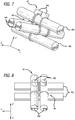
Figures 7-12 , the production ofcomplex coils 40 are shown using afixture 42 that includes a plurality of pins 44 arranged at right angles to each other. Like the embodiments shown inFigures 1-6 , the embodiments of thecomplex coils 40 formed using thefixture 42 inFigures 7-12 may be made from a length of wire that has been helically wound to form a coiled wire. Alternatively, the wire may be braided or knitted by methods known in the art to form a secondary shape. The wire may be platinum, tantalum, tungsten, stainless steel, Nitinol, or other biocompatible material. Other materials, such as Dacron or Nylon fibers, biodegradable polymers such as polylactic or polyglycolic acid, and expansible or non-expansible hydrogel materials may be placed inside or outside the complex coil or braid structure to enhance the performance of the device. By way of example only, one embodiment might be used to treat such conditions as cerebral aneurysms, employs a platinum/tungsten alloy complex coil 10 (92% PT, 8% W available from Sigmund Cohn Mount Vernon, NY) with a diameter in the range of about 0.125 mm to about 0.625 mm and a length of about 5 mm to about 1000 mm. - The
complex coil 40 is formed by wrapping a coiled wire around thefixture 42, as shown inFigures 7-8 . Thefixture 42 is preferably a ceramic or metallic cruciform fixture and includes a plurality of pins 44 arranged at right angles to each other along axes x, y, and z. More specifically, thefixture 42 includes twopins 44x that are parallel to the x-axis, twopins 44y that are parallel to the y-axis, and twopins 44z that are parallel to the z-axis. - An example of a
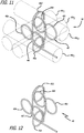
complex coil 40 that can be made using thefixture 42 ofFigures 7-8 is shown inFigures 9-12 . The winding pattern in this embodiment, shown most clearly inFigures 11-12 , forms afirst loop 46a around afirst pin 44y1, then asecond loop 46b around asecond pin 44x1 that is disposed at an angle to thefirst pin 44y1. In this embodiment the angle between theloops third loop 46c is then formed in approximately the same plane as thesecond loop 46b. In this example, thethird loop 46c is formed aroundpin 44x2 in afigure 8 pattern with thesecond loop 46b. Afourth loop 46d is then formed at an angle with thethird loop 46c. In this example, thefourth loop 46d is approximately 45°-135° to the third loop and is formed aroundpin 44y2 and is also approximately coplanar to thefirst loop 46a. Afifth loop 46e is then formed at an angle to thefourth loop 46d by wrapping the wire aroundpin 44x1 spaced apart fromloop 46b, also formed aroundpin 44x1. Asixth loop 46f lies in approximately the same plane as thefifth loop 46e in afigure 8 pattern with thefifth loop 46e. Thesixth loop 46f is formed by wrapping the wire aroundpin 44x2 spaced apart fromloop 46c, which is also formed aroundpin 44x2. In this example, thefifth loop 46e and thesixth loop 46f are approximately concentric with thesecond loop 46b and thethird loop 46c, respectively. - Fewer than six loops may be used to form shorter complex coils, while additional loops may be wound to make a longer device. For example, the
pins 44z shown inFigures 7-8 extend through thepins pins pins 44z extending from thepins 44y. - Furthermore, those skilled in the art will appreciate that the same final result could be obtained by reversing the just-described winding pattern: i.e. winding a first loop around a first pin, winding a second loop in approximately the same plane as the first loop, winding a third loop at an angle to the second loop, winding a fourth loop at an angle to the third loop, winding a fifth loop in approximately the same plane as the fourth loop, winding a sixth loop at an angle to the fifth loop, and so on.
- The loops can form a closed structure such as an "O" shape (e.g. circle, oval, square, ellipse, star, etc.) or can be open such as a "C" or "U" shape. The loops may be of any dimension and are typically scaled to the approximate size of the treatment site. In the previous example, the loops may range from 0.5 mm diameter to 50 mm diameter.
In this regard, "diameter" should not be narrowly construed to imply a circular dimension. Rather, diameter is used broadly to encompass the approximate size and shape of a loop. - For example, the
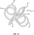
coil 50 shown inFigure 13 has loops 52 that are open and closed. The open loops are formed by wrapping a wire around a pin but transitioning to an adjacent pin prior to completing an overlapping loop. More specifically, thecomplex coil 50 ofFigure 13 has sixloops 52a-f formed using thefixture 42 ofFigures 7 and 8 .Loop 52a is a complete loop formed around one of thepins 44y. The wire is then wrapped in afigure 8 pattern around twoadjacent pins 44x to formopen loops complete loop 52d. Next, the wire is wrapped in afigure 8 pattern around the twopins 44y on the opposite side ofpins 44x to formloops loop 52e is open but theloop 52f is closed, being the last loop. - Further complexity may be introduced using the
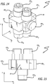
fixture 60 shown inFigures 14-15 . Thefixture 60 inFigures 14-15 also has a plurality of pins 62 but differs from thefixture 42 inFigures 7 and 8 in three substantive ways. First, the pins 62 extend in directions parallel with x- and y-axes, but there are no pins that extend parallel to a z-axis. Rather,rectangular blocks 64 extend along the z-axis. Second, there are only two concentric pins, 62x1 and 62x2 that extend parallel to the x-axis. Third, there are four pins 62y1-4, each having independent longitudinal axes. Winding using thefixture 60 results incomplex coils 70 such as those shown inFigures 16-19 . These figures show acomplex coil 70 with first and second loops, 74a and 74b, that are substantially coplanar and arranged in afigure 8 pattern, as well as third and forth loops, 74c and 74d that are similarly substantially coplanar and arranged in afigure 8 pattern that is rotated from thefigure 8 pattern of the first and second loops, 74a and 74b. The examples shown inFigures 16-19 show the twofigure 8 patterns rotated 90 degrees relative to each other. Additionally, thecomplex coils 70 include fifth and sixth loops, 74e and 74f, which are relatively concentric. - After winding, the fixture and complex coil are heat-set by methods known in the art. For example, a typical annealing step for platinum complex coils is approximately 1100° F (593°C) for 5-60 minutes.
- Once annealed, the complex coil will approximately retain the wound shape when substantially in a minimal energy state. The complex coil may then be subject to further processing such as forming a tip, adding a coupling mechanism for attachment to a delivery system, placing hydrogel or fibers onto or within the complex coil, placing a stretch resistant member inside or outside the complex coil, etc. The complex coil can then be attached to a delivery system, which is well known in the art, such as those disclosed in
U.S. Patent Application Serial Number 11/212,830 , entitled Thermal Detachment System for Implantable Devices. Other examples of delivery systems are disclosed in Guglielmi 6,010,498 or Gandhi 6,478,773. Once attached to the delivery pusher, thecomplex coil 10 is placed in a substantially linear configuration within a tube for delivery to the treatment site. - In the typical procedure, the linear complex coil is fed through a conduit such as a microcatheter by advancing it through the conduit with the delivery pusher. Upon exiting the microcatheter, the complex coil then self-forms into a structure within the treatment site that approximates its annealed shape.
- Although the invention has been described in terms of particular embodiments and applications, one of ordinary skill in the art, in light of this teaching, can generate additional embodiments and modifications without departing from or exceeding the scope of the claimed invention as defined by the claims. Accordingly, it is to be understood that the drawings and descriptions herein are proffered by way of example to facilitate comprehension of the invention and should not be construed to limit the scope thereof, which is defined by the claims.
Claims (14)
- A complex coil (40, 50, 70) comprising:a first and second loop (46b, 46c; 52b, 52c; 74a, 74b) aligned to form a first figure 8 pattern in a first plane;a third and fourth loop (46e, 46f; 52e, 52f; 74c, 74d) aligned to form a second figure 8 pattern in a second plane; characterized in thatsaid first and second plane are spaced apart and substantially parallel to each other, and said first figure 8 pattern and said second figure 8 pattern are facing each other.
- The complex coil according to claim 1 wherein none of said first, second, third and fourth loops (46b, 46c; 52b, 52c; 74a, 74b; 46e, 46f; 52e, 52f; 74c, 74d) share a common longitudinal axis.
- The complex coil according to claim 1 or 2 wherein said first figure 8 pattern is rotated within said first plane relative to said second figure 8 pattern.
- The complex coil according to claim 3 wherein said first figure 8 pattern is rotated approximately 90 degrees within said first plane relative to said second figure 8 pattern.
- The complex coil according to claim 1 wherein said first and third loops (46b, 46e; 52b, 52c) have a common longitudinal axis.
- The complex coil according to claim 1 wherein said second and fourth loops (46c, 46f; 52e, 52f) have a common longitudinal axis.
- The complex coil according to any of claims 1 to 6, further comprising fifth and sixth loops (46a, 46d; 52a, 52d; 74e, 74f) having longitudinal axes that are angled approximately 90 degrees relative to longitudinal axes of the first, second, third, and fourth loops (46b, 46c; 52b, 52c; 74a, 74b; 46e, 46f; 52e, 52f; 74c, 74d).
- The complex coil according to claim 7 wherein said fifth and sixth loops have a common longitudinal axis(74e, 74f) .
- A method of making a complex coil (40, 50, 70) comprising:forming a first and second loop (46b, 46c; 52b, 52c; 74a, 74b) in a first figure 8 pattern relatively contained in a first plane;forming a third and fourth loop (46e, 46f; 52e, 52f; 74c, 74d) in a second figure 8 pattern relatively contained in a second plane; characterized byforming said first and second plane spaced apart and substantially parallel to each other; andforming said first figure 8 pattern and said second figure 8 pattern to face each other.
- The method according to claim 9 further comprising forming at least one loop (46d; 52d; 74f) connecting said first and second figure 8 patterns, said at least one complete loop (46d; 52d; 74f) defining a third plane that is perpendicular to said first and second planes.
- The method according to claim 10 wherein forming at least one loop (46d; 52d; 74f) connecting said first and second figure 8 patterns comprises forming two loops (46a, 46d; 52a, 52d; 74e, 74f) defining a third and fourth planes that are both perpendicular to said first and second planes.
- The method according to claim 11 wherein forming two loops (46a, 46d; 52a, 52d; 74e, 74f) defining a third and fourth planes that are both perpendicular to said first and second planes comprises two loops (46a, 46d; 52a, 52d; 74e, 74f) defining a third and fourth planes that are both perpendicular to said first and second planes and are further parallel to each other.
- The method according to claim 9 wherein forming a first and second loop (52b, 52c) in a first figure 8 pattern relatively contained in a first plane comprises forming at least one open loop (52b, 52c), and/or wherein forming a third and a fourth loop (52e, 52f)in a second figure 8 pattern relatively contained in a second plane comprises forming at least one open loop (52e).
- The method according to any of claims 9 to 13, wherein said complex coil (40, 50, 70) is a complex coil (40, 50, 70) according to any of claims 1 to 8, said method comprising using a fixture (42, 60) to form said complex coil (40, 50, 70).
Applications Claiming Priority (3)
| Application Number | Priority Date | Filing Date | Title |
|---|---|---|---|
| US73808705P | 2005-11-17 | 2005-11-17 | |
| US82265606P | 2006-08-17 | 2006-08-17 | |
| PCT/US2006/060923 WO2007076179A2 (en) | 2005-11-17 | 2006-11-15 | Three-dimensional complex coil |
Publications (3)
| Publication Number | Publication Date |
|---|---|
| EP1973680A2 EP1973680A2 (en) | 2008-10-01 |
| EP1973680A4 EP1973680A4 (en) | 2015-03-25 |
| EP1973680B1 true EP1973680B1 (en) | 2018-01-10 |
Family
ID=38218744
Family Applications (1)
| Application Number | Title | Priority Date | Filing Date |
|---|---|---|---|
| EP06848957.4A Active EP1973680B1 (en) | 2005-11-17 | 2006-11-15 | Three-dimensional complex coil |
Country Status (7)
| Country | Link |
|---|---|
| US (4) | US8066036B2 (en) |
| EP (1) | EP1973680B1 (en) |
| JP (2) | JP5154432B2 (en) |
| CN (1) | CN101394955B (en) |
| AU (1) | AU2006330786B2 (en) |
| CA (1) | CA2630021C (en) |
| WO (1) | WO2007076179A2 (en) |
Families Citing this family (222)
| Publication number | Priority date | Publication date | Assignee | Title |
|---|---|---|---|---|
| US8425549B2 (en) | 2002-07-23 | 2013-04-23 | Reverse Medical Corporation | Systems and methods for removing obstructive matter from body lumens and treating vascular defects |
| US9675476B2 (en) | 2004-05-25 | 2017-06-13 | Covidien Lp | Vascular stenting for aneurysms |
| JP2008502378A (en) | 2004-05-25 | 2008-01-31 | チェストナット メディカル テクノロジーズ インコーポレイテッド | Flexible vascular closure device |
| KR101300437B1 (en) | 2004-05-25 | 2013-08-26 | 코비디엔 엘피 | Vascular stenting for aneurysms |
| WO2007047851A2 (en) | 2005-10-19 | 2007-04-26 | Pulsar Vascular, Inc. | Methods and systems for endovascularly clipping and repairing lumen and tissue defects |
| US8152833B2 (en) | 2006-02-22 | 2012-04-10 | Tyco Healthcare Group Lp | Embolic protection systems having radiopaque filter mesh |
| US8585713B2 (en) | 2007-10-17 | 2013-11-19 | Covidien Lp | Expandable tip assembly for thrombus management |
| US8088140B2 (en) | 2008-05-19 | 2012-01-03 | Mindframe, Inc. | Blood flow restorative and embolus removal methods |
| US8926680B2 (en) * | 2007-11-12 | 2015-01-06 | Covidien Lp | Aneurysm neck bridging processes with revascularization systems methods and products thereby |
| US8545514B2 (en) | 2008-04-11 | 2013-10-01 | Covidien Lp | Monorail neuro-microcatheter for delivery of medical devices to treat stroke, processes and products thereby |
| US20100256600A1 (en) * | 2009-04-04 | 2010-10-07 | Ferrera David A | Neurovascular otw pta balloon catheter and delivery system |
| US8066757B2 (en) | 2007-10-17 | 2011-11-29 | Mindframe, Inc. | Blood flow restoration and thrombus management methods |
| US9220522B2 (en) * | 2007-10-17 | 2015-12-29 | Covidien Lp | Embolus removal systems with baskets |
| US10123803B2 (en) | 2007-10-17 | 2018-11-13 | Covidien Lp | Methods of managing neurovascular obstructions |
| US20100174309A1 (en) * | 2008-05-19 | 2010-07-08 | Mindframe, Inc. | Recanalization/revascularization and embolus addressing systems including expandable tip neuro-microcatheter |
| US9198687B2 (en) * | 2007-10-17 | 2015-12-01 | Covidien Lp | Acute stroke revascularization/recanalization systems processes and products thereby |
| JP5457373B2 (en) | 2008-02-22 | 2014-04-02 | コヴィディエン リミテッド パートナーシップ | Device for blood flow recovery |
| AU2009239424B9 (en) | 2008-04-21 | 2014-10-09 | Covidien Lp | Braid-ball embolic devices and delivery systems |
| US10716573B2 (en) | 2008-05-01 | 2020-07-21 | Aneuclose | Janjua aneurysm net with a resilient neck-bridging portion for occluding a cerebral aneurysm |
| US10028747B2 (en) | 2008-05-01 | 2018-07-24 | Aneuclose Llc | Coils with a series of proximally-and-distally-connected loops for occluding a cerebral aneurysm |
| US9675482B2 (en) | 2008-05-13 | 2017-06-13 | Covidien Lp | Braid implant delivery systems |
| US9402707B2 (en) | 2008-07-22 | 2016-08-02 | Neuravi Limited | Clot capture systems and associated methods |
| KR101652804B1 (en) | 2008-09-05 | 2016-08-31 | 펄사 배스큘라, 아이엔씨. | Systems and methods for supporting or occluding a physiological opening or cavity |
| US9089405B1 (en) * | 2008-09-12 | 2015-07-28 | Microvention, Inc. | Three-dimensional complex coil |
| HUE033632T2 (en) * | 2009-01-18 | 2017-12-28 | Ocon Medical Ltd | Novel intra uterine device |
| WO2010085344A1 (en) * | 2009-01-22 | 2010-07-29 | Cornell University | Method and apparatus for restricting flow through the wall of a lumen |
| US8409269B2 (en) | 2009-12-21 | 2013-04-02 | Covidien Lp | Procedures for vascular occlusion |
| US9358140B1 (en) | 2009-11-18 | 2016-06-07 | Aneuclose Llc | Stent with outer member to embolize an aneurysm |
| US8998947B2 (en) | 2010-09-10 | 2015-04-07 | Medina Medical, Inc. | Devices and methods for the treatment of vascular defects |
| EP3354210B1 (en) | 2010-09-10 | 2022-10-26 | Covidien LP | Devices for the treatment of vascular defects |
| ES2683943T3 (en) | 2010-10-22 | 2018-09-28 | Neuravi Limited | Clot capture and removal system |
| US8915950B2 (en) | 2010-12-06 | 2014-12-23 | Covidien Lp | Vascular remodeling device |
| WO2012120490A2 (en) | 2011-03-09 | 2012-09-13 | Neuravi Limited | A clot retrieval device for removing occlusive clot from a blood vessel |
| US11259824B2 (en) | 2011-03-09 | 2022-03-01 | Neuravi Limited | Clot retrieval device for removing occlusive clot from a blood vessel |
| WO2012134990A1 (en) | 2011-03-25 | 2012-10-04 | Tyco Healthcare Group Lp | Vascular remodeling device |
| WO2012135859A2 (en) * | 2011-04-01 | 2012-10-04 | Cornell University | Method and apparatus for restricting flow through an opening in the side wall of a body lumen, and/or for reinforcing a weakness in the side wall of a body lumen, while still maintaining substantially normal flow through the body lumen |
| EP2706926B1 (en) | 2011-05-11 | 2016-11-30 | Covidien LP | Vascular remodeling device |
| CN103826688B (en) * | 2011-05-11 | 2016-10-19 | 微排放器公司 | Filling coil |
| EP2713904B1 (en) | 2011-06-03 | 2018-01-10 | Pulsar Vascular, Inc. | Aneurysm devices with additional anchoring mechanisms and associated systems |
| EP4101399A1 (en) | 2011-08-05 | 2022-12-14 | Route 92 Medical, Inc. | System for treatment of acute ischemic stroke |
| WO2013049448A1 (en) | 2011-09-29 | 2013-04-04 | Covidien Lp | Vascular remodeling device |
| US9662704B2 (en) * | 2011-10-05 | 2017-05-30 | Marius S. Winograd | Method for forming a spiral support structure with continuous wire coil |
| JP6174033B2 (en) | 2011-10-05 | 2017-08-02 | パルサー バスキュラー インコーポレイテッド | Aneurysm device |
| EP2763601B1 (en) * | 2011-10-07 | 2020-03-25 | Cornell University | Apparatus for restricting flow through an opening in a body lumen while maintaining normal flow |
| US9072620B2 (en) | 2011-11-04 | 2015-07-07 | Covidien Lp | Protuberant aneurysm bridging device deployment method |
| US9011480B2 (en) | 2012-01-20 | 2015-04-21 | Covidien Lp | Aneurysm treatment coils |
| JP6119749B2 (en) * | 2012-06-29 | 2017-04-26 | 株式会社カネカ | Method for producing in-vivo indwelling member |
| US20150297238A1 (en) * | 2012-08-19 | 2015-10-22 | Christopher G.M. Ken | Geometric coil |
| US9452070B2 (en) | 2012-10-31 | 2016-09-27 | Covidien Lp | Methods and systems for increasing a density of a region of a vascular device |
| US10327781B2 (en) | 2012-11-13 | 2019-06-25 | Covidien Lp | Occlusive devices |
| US10603157B2 (en) | 2013-03-13 | 2020-03-31 | DePuy Synthes Products, Inc. | Braid implant delivery and retraction device with distal engagement |
| US10561509B2 (en) | 2013-03-13 | 2020-02-18 | DePuy Synthes Products, Inc. | Braided stent with expansion ring and method of delivery |
| US9433429B2 (en) | 2013-03-14 | 2016-09-06 | Neuravi Limited | Clot retrieval devices |
| CN105208950A (en) | 2013-03-14 | 2015-12-30 | 尼尔拉维有限公司 | A clot retrieval device for removing occlusive clot from a blood vessel |
| PL2967611T3 (en) | 2013-03-14 | 2019-08-30 | Neuravi Limited | Devices for removal of acute blockages from blood vessels |
| CN108433769B (en) | 2013-03-15 | 2021-06-08 | 柯惠有限合伙公司 | Occlusion device |
| CN105142543B (en) | 2013-03-15 | 2019-06-04 | 柯惠有限合伙公司 | The conveying of Vascular implant and separating mechanism |
| EP3068337B1 (en) | 2013-11-13 | 2022-10-05 | Covidien LP | Galvanically assisted attachment of medical devices to thrombus |
| US20170000495A1 (en) * | 2013-12-18 | 2017-01-05 | Blockade Medical, LLC | Implant System and Delivery Method |
| US10398441B2 (en) | 2013-12-20 | 2019-09-03 | Terumo Corporation | Vascular occlusion |
| US9265512B2 (en) | 2013-12-23 | 2016-02-23 | Silk Road Medical, Inc. | Transcarotid neurovascular catheter |
| JP6566961B2 (en) * | 2014-02-27 | 2019-08-28 | インキュメデックス インコーポレイテッド | Emboli frame microcoil |
| US10285720B2 (en) | 2014-03-11 | 2019-05-14 | Neuravi Limited | Clot retrieval system for removing occlusive clot from a blood vessel |
| US11076860B2 (en) | 2014-03-31 | 2021-08-03 | DePuy Synthes Products, Inc. | Aneurysm occlusion device |
| US11154302B2 (en) | 2014-03-31 | 2021-10-26 | DePuy Synthes Products, Inc. | Aneurysm occlusion device |
| US9713475B2 (en) | 2014-04-18 | 2017-07-25 | Covidien Lp | Embolic medical devices |
| WO2015178282A1 (en) * | 2014-05-19 | 2015-11-26 | 株式会社カネカ | In vivo indwelling member and method for producing same |
| WO2015189354A1 (en) | 2014-06-13 | 2015-12-17 | Neuravi Limited | Devices for removal of acute blockages from blood vessels |
| US10265086B2 (en) | 2014-06-30 | 2019-04-23 | Neuravi Limited | System for removing a clot from a blood vessel |
| CA2955953A1 (en) * | 2014-07-25 | 2016-01-28 | Incumedx, Inc. | Covered embolic coils |
| US9814466B2 (en) | 2014-08-08 | 2017-11-14 | Covidien Lp | Electrolytic and mechanical detachment for implant delivery systems |
| US9918718B2 (en) | 2014-08-08 | 2018-03-20 | DePuy Synthes Products, Inc. | Embolic coil delivery system with retractable mechanical release mechanism |
| US10206796B2 (en) | 2014-08-27 | 2019-02-19 | DePuy Synthes Products, Inc. | Multi-strand implant with enhanced radiopacity |
| US9782178B2 (en) | 2014-09-19 | 2017-10-10 | DePuy Synthes Products, Inc. | Vasculature occlusion device detachment system with tapered corewire and heater activated fiber detachment |
| US10617435B2 (en) | 2014-11-26 | 2020-04-14 | Neuravi Limited | Clot retrieval device for removing clot from a blood vessel |
| US11253278B2 (en) | 2014-11-26 | 2022-02-22 | Neuravi Limited | Clot retrieval system for removing occlusive clot from a blood vessel |
| EP3223723B1 (en) | 2014-11-26 | 2020-01-08 | Neuravi Limited | A clot retrieval device for removing occlusive clot from a blood vessel |
| ES2932764T3 (en) | 2015-02-04 | 2023-01-26 | Route 92 Medical Inc | Rapid Aspiration Thrombectomy System |
| US10426497B2 (en) | 2015-07-24 | 2019-10-01 | Route 92 Medical, Inc. | Anchoring delivery system and methods |
| US11065019B1 (en) | 2015-02-04 | 2021-07-20 | Route 92 Medical, Inc. | Aspiration catheter systems and methods of use |
| US10478194B2 (en) | 2015-09-23 | 2019-11-19 | Covidien Lp | Occlusive devices |
| US10314593B2 (en) | 2015-09-23 | 2019-06-11 | Covidien Lp | Occlusive devices |
| WO2017086477A1 (en) * | 2015-11-19 | 2017-05-26 | 株式会社カネカ | In vivo indwelling member, and in vivo indwelling member placement device provided with said in vivo indwelling member |
| EP3419528B1 (en) | 2016-02-24 | 2023-06-07 | Incept, LLC | Enhanced flexibility neurovascular catheter |
| WO2017165833A1 (en) | 2016-03-24 | 2017-09-28 | Covidien Lp | Thin wall constructions for vascular flow diversion |
| US10518927B2 (en) | 2016-04-14 | 2019-12-31 | All Packaging Company | Locking packaging container |
| CA2964207C (en) * | 2016-04-14 | 2023-01-31 | All Packaging Company | Locking packaging container |
| CA3017770A1 (en) * | 2016-05-13 | 2017-11-16 | Covidien Lp | Aneurysm treatment coils |
| US10285710B2 (en) | 2016-06-01 | 2019-05-14 | DePuy Synthes Products, Inc. | Endovascular detachment system with flexible distal end and heater activated detachment |
| US10828037B2 (en) | 2016-06-27 | 2020-11-10 | Covidien Lp | Electrolytic detachment with fluid electrical connection |
| US10828039B2 (en) | 2016-06-27 | 2020-11-10 | Covidien Lp | Electrolytic detachment for implantable devices |
| US11051822B2 (en) | 2016-06-28 | 2021-07-06 | Covidien Lp | Implant detachment with thermal activation |
| US10478195B2 (en) | 2016-08-04 | 2019-11-19 | Covidien Lp | Devices, systems, and methods for the treatment of vascular defects |
| ES2834299T3 (en) | 2016-08-17 | 2021-06-17 | Neuravi Ltd | A clot removal device to remove an occlusive clot from a blood vessel |
| US10076428B2 (en) | 2016-08-25 | 2018-09-18 | DePuy Synthes Products, Inc. | Expansion ring for a braided stent |
| MX2019002565A (en) | 2016-09-06 | 2019-09-18 | Neuravi Ltd | A clot retrieval device for removing occlusive clot from a blood vessel. |
| US10292851B2 (en) | 2016-09-30 | 2019-05-21 | DePuy Synthes Products, Inc. | Self-expanding device delivery apparatus with dual function bump |
| US10842607B2 (en) | 2016-10-14 | 2020-11-24 | Microvention, Inc. | Embolic coils |
| US10576099B2 (en) | 2016-10-21 | 2020-03-03 | Covidien Lp | Injectable scaffold for treatment of intracranial aneurysms and related technology |
| US10517708B2 (en) | 2016-10-26 | 2019-12-31 | DePuy Synthes Products, Inc. | Multi-basket clot capturing device |
| JP7264581B2 (en) | 2017-01-06 | 2023-04-25 | インセプト、リミテッド、ライアビリティ、カンパニー | Antithrombotic coating for aneurysm treatment devices |
| EP3568186B1 (en) | 2017-01-10 | 2022-09-14 | Route 92 Medical, Inc. | Aspiration catheter systems |
| US10905853B2 (en) | 2017-01-17 | 2021-02-02 | DePuy Synthes Products, Inc. | System and method for delivering a catheter |
| US10881497B2 (en) | 2017-01-26 | 2021-01-05 | DePuy Synthes Products, Inc. | Composite vascular flow diverter |
| RU2019129526A (en) | 2017-02-23 | 2021-03-23 | Депуи Синтез Продактс, Инк. | DEVICE AND DELIVERY SYSTEM FOR ANEURYSM TREATMENT |
| EP3596835B1 (en) * | 2017-03-17 | 2022-06-08 | Efficient Power Conversion Corporation | Antenna with large area scalable highly resonant wireless power coil |
| US10675036B2 (en) | 2017-08-22 | 2020-06-09 | Covidien Lp | Devices, systems, and methods for the treatment of vascular defects |
| US10806462B2 (en) | 2017-12-21 | 2020-10-20 | DePuy Synthes Products, Inc. | Implantable medical device detachment system with split tube and cylindrical coupling |
| US10751065B2 (en) | 2017-12-22 | 2020-08-25 | DePuy Synthes Products, Inc. | Aneurysm device and delivery system |
| US10905430B2 (en) | 2018-01-24 | 2021-02-02 | DePuy Synthes Products, Inc. | Aneurysm device and delivery system |
| US11065009B2 (en) | 2018-02-08 | 2021-07-20 | Covidien Lp | Vascular expandable devices |
| US11065136B2 (en) | 2018-02-08 | 2021-07-20 | Covidien Lp | Vascular expandable devices |
| US10918390B2 (en) | 2018-03-30 | 2021-02-16 | DePuy Synthes Products, Inc. | Helical balloon assist device and method for using the same |
| US10786259B2 (en) | 2018-03-30 | 2020-09-29 | DePuy Synthes Products, Inc. | Split balloon assist device and method for using the same |
| US10806461B2 (en) | 2018-04-27 | 2020-10-20 | DePuy Synthes Products, Inc. | Implantable medical device detachment system with split tube |
| CN112203593A (en) | 2018-05-01 | 2021-01-08 | 因赛普特有限责任公司 | Device and method for removing occlusive material from an intravascular site |
| US11395665B2 (en) | 2018-05-01 | 2022-07-26 | Incept, Llc | Devices and methods for removing obstructive material, from an intravascular site |
| JP2021523793A (en) | 2018-05-17 | 2021-09-09 | ルート92メディカル・インコーポレイテッドRoute 92 Medical, Inc. | Suction catheter system and how to use |
| US11596412B2 (en) | 2018-05-25 | 2023-03-07 | DePuy Synthes Products, Inc. | Aneurysm device and delivery system |
| US11058430B2 (en) | 2018-05-25 | 2021-07-13 | DePuy Synthes Products, Inc. | Aneurysm device and delivery system |
| US10939915B2 (en) | 2018-05-31 | 2021-03-09 | DePuy Synthes Products, Inc. | Aneurysm device and delivery system |
| US10667833B2 (en) | 2018-06-08 | 2020-06-02 | Neuravi Limited | Guidewire with an atraumatic clot-circumventing configured distal end for use in an endovascular medical system |
| US10898216B2 (en) | 2018-06-13 | 2021-01-26 | DePuy Synthes Products, Inc. | Vasculature obstruction capture device |
| US11517335B2 (en) | 2018-07-06 | 2022-12-06 | Incept, Llc | Sealed neurovascular extendable catheter |
| US11471582B2 (en) | 2018-07-06 | 2022-10-18 | Incept, Llc | Vacuum transfer tool for extendable catheter |
| AU2019204522A1 (en) | 2018-07-30 | 2020-02-13 | DePuy Synthes Products, Inc. | Systems and methods of manufacturing and using an expansion ring |
| US10905431B2 (en) | 2018-08-03 | 2021-02-02 | DePuy Synthes Products, Inc. | Spiral delivery system for embolic braid |
| US10456280B1 (en) | 2018-08-06 | 2019-10-29 | DePuy Synthes Products, Inc. | Systems and methods of using a braided implant |
| US10278848B1 (en) | 2018-08-06 | 2019-05-07 | DePuy Synthes Products, Inc. | Stent delivery with expansion assisting delivery wire |
| US10813780B2 (en) | 2018-08-08 | 2020-10-27 | DePuy Synthes Products, Inc. | Intraluminal implant delivery system and method |
| US11051825B2 (en) | 2018-08-08 | 2021-07-06 | DePuy Synthes Products, Inc. | Delivery system for embolic braid |
| US10905432B2 (en) * | 2018-08-22 | 2021-02-02 | Covidien Lp | Aneurysm treatment coils and associated systems and methods of use |
| US10912569B2 (en) * | 2018-08-22 | 2021-02-09 | Covidien Lp | Aneurysm treatment coils and associated systems and methods of use |
| US10842498B2 (en) | 2018-09-13 | 2020-11-24 | Neuravi Limited | Systems and methods of restoring perfusion to a vessel |
| KR20200033757A (en) | 2018-09-20 | 2020-03-30 | 디퍼이 신테스 프로덕츠, 인코포레이티드 | Stent with shaped wires |
| US11123077B2 (en) | 2018-09-25 | 2021-09-21 | DePuy Synthes Products, Inc. | Intrasaccular device positioning and deployment system |
| US11406416B2 (en) | 2018-10-02 | 2022-08-09 | Neuravi Limited | Joint assembly for vasculature obstruction capture device |
| US11253287B2 (en) | 2018-10-04 | 2022-02-22 | Neuravi Limited | Retrograde blood flow occlusion flushing device |
| CN108814669B (en) * | 2018-10-09 | 2019-02-05 | 微创神通医疗科技(上海)有限公司 | Embolization device and its spring ring |
| US11076861B2 (en) | 2018-10-12 | 2021-08-03 | DePuy Synthes Products, Inc. | Folded aneurysm treatment device and delivery method |
| US11406392B2 (en) | 2018-12-12 | 2022-08-09 | DePuy Synthes Products, Inc. | Aneurysm occluding device for use with coagulating agents |
| US11147562B2 (en) | 2018-12-12 | 2021-10-19 | DePuy Synthes Products, Inc. | Systems and methods for embolic implant detachment |
| CN111491575A (en) | 2018-12-17 | 2020-08-04 | 柯惠有限合伙公司 | Devices, systems, and methods for treating vascular defects |
| US11272939B2 (en) | 2018-12-18 | 2022-03-15 | DePuy Synthes Products, Inc. | Intrasaccular flow diverter for treating cerebral aneurysms |
| US11039944B2 (en) | 2018-12-27 | 2021-06-22 | DePuy Synthes Products, Inc. | Braided stent system with one or more expansion rings |
| US11134953B2 (en) | 2019-02-06 | 2021-10-05 | DePuy Synthes Products, Inc. | Adhesive cover occluding device for aneurysm treatment |
| US11273285B2 (en) | 2019-02-07 | 2022-03-15 | DePuy Synthes Products, Inc. | Ancillary device for detaching implants |
| EP3705066B1 (en) | 2019-03-04 | 2021-12-29 | Neuravi Limited | Actuated clot retrieval catheter |
| US11382633B2 (en) | 2019-03-06 | 2022-07-12 | DePuy Synthes Products, Inc. | Strut flow diverter for cerebral aneurysms and methods for preventing strut entanglement |
| US11559309B2 (en) | 2019-03-15 | 2023-01-24 | Sequent Medical, Inc. | Filamentary devices for treatment of vascular defects |
| US11337706B2 (en) | 2019-03-27 | 2022-05-24 | DePuy Synthes Products, Inc. | Aneurysm treatment device |
| US11185334B2 (en) | 2019-03-28 | 2021-11-30 | DePuy Synthes Products, Inc. | Single lumen reduced profile occlusion balloon catheter |
| US11766539B2 (en) | 2019-03-29 | 2023-09-26 | Incept, Llc | Enhanced flexibility neurovascular catheter |
| US11051928B2 (en) | 2019-04-11 | 2021-07-06 | Neuravi Limited | Floating carotid filter |
| US11571553B2 (en) | 2019-05-09 | 2023-02-07 | Neuravi Limited | Balloon guide catheter with thermally expandable material |
| US11931522B2 (en) | 2019-05-09 | 2024-03-19 | Neuravi Limited | Inflation lumen kink protection and balloon profile |
| US11607531B2 (en) | 2019-05-09 | 2023-03-21 | Neuravi Limited | Balloon catheter with venting of residual air in a proximal direction |
| US11957855B2 (en) | 2019-05-09 | 2024-04-16 | Neuravi Limited | Balloon guide catheter with positive venting of residual air |
| USD959659S1 (en) | 2019-05-10 | 2022-08-02 | DePuy Synthes Products, Inc. | Implant release handle |
| US11602350B2 (en) | 2019-12-05 | 2023-03-14 | DePuy Synthes Products, Inc. | Intrasaccular inverting braid with highly flexible fill material |
| US11672542B2 (en) | 2019-05-21 | 2023-06-13 | DePuy Synthes Products, Inc. | Aneurysm treatment with pushable ball segment |
| US11497504B2 (en) | 2019-05-21 | 2022-11-15 | DePuy Synthes Products, Inc. | Aneurysm treatment with pushable implanted braid |
| US10653425B1 (en) | 2019-05-21 | 2020-05-19 | DePuy Synthes Products, Inc. | Layered braided aneurysm treatment device |
| US11413046B2 (en) | 2019-05-21 | 2022-08-16 | DePuy Synthes Products, Inc. | Layered braided aneurysm treatment device |
| US11607226B2 (en) | 2019-05-21 | 2023-03-21 | DePuy Synthes Products, Inc. | Layered braided aneurysm treatment device with corrugations |
| US11278292B2 (en) | 2019-05-21 | 2022-03-22 | DePuy Synthes Products, Inc. | Inverting braided aneurysm treatment system and method |
| US11406403B2 (en) | 2019-06-14 | 2022-08-09 | Neuravi Limited | Visibility of mechanical thrombectomy device during diagnostic imaging |
| US11109939B2 (en) | 2019-06-14 | 2021-09-07 | DePuy Synthes Products, Inc. | Intravascular devices with radiopaque body markers |
| US11253265B2 (en) | 2019-06-18 | 2022-02-22 | DePuy Synthes Products, Inc. | Pull wire detachment for intravascular devices |
| US11426174B2 (en) | 2019-10-03 | 2022-08-30 | DePuy Synthes Products, Inc. | Medical device delivery member with flexible stretch resistant mechanical release |
| US11207494B2 (en) | 2019-07-03 | 2021-12-28 | DePuy Synthes Products, Inc. | Medical device delivery member with flexible stretch resistant distal portion |
| US11266426B2 (en) | 2019-07-10 | 2022-03-08 | DePuy Synthes Products, Inc. | Streamlined treatment of clot removal, angioplasty and prevention of restenosis using a single integrated intravascular device |
| US11266427B2 (en) | 2019-07-10 | 2022-03-08 | Neuravi Limited | Self-expanding intravascular medical device |
| US11395675B2 (en) | 2019-07-11 | 2022-07-26 | DePuy Synthes Products, Inc. | Clot retriever cleaning for reinsertion |
| US11399840B2 (en) | 2019-08-13 | 2022-08-02 | Covidien Lp | Implantable embolization device |
| JP2021041169A (en) | 2019-09-11 | 2021-03-18 | ニューラヴィ・リミテッド | Expandable mouth catheter |
| CN114615940A (en) * | 2019-09-13 | 2022-06-10 | 阿万泰血管公司 | Intravascular coil and method for manufacturing same |
| US11439403B2 (en) | 2019-09-17 | 2022-09-13 | DePuy Synthes Products, Inc. | Embolic coil proximal connecting element and stretch resistant fiber |
| CN113347916A (en) | 2019-10-15 | 2021-09-03 | 因普瑞缇夫护理公司 | System and method for multivariate stroke detection |
| US11712231B2 (en) | 2019-10-29 | 2023-08-01 | Neuravi Limited | Proximal locking assembly design for dual stent mechanical thrombectomy device |
| EP4054440A1 (en) | 2019-11-04 | 2022-09-14 | Covidien LP | Devices, systems, and methods for treatment of intracranial aneurysms |
| US20210137526A1 (en) * | 2019-11-11 | 2021-05-13 | Stryker Corporation | Embolic devices for occluding body lumens |
| US11376013B2 (en) | 2019-11-18 | 2022-07-05 | DePuy Synthes Products, Inc. | Implant delivery system with braid cup formation |
| US11628282B2 (en) | 2019-11-25 | 2023-04-18 | Neuravi Limited | No preparation balloon guide catheter |
| US11839725B2 (en) | 2019-11-27 | 2023-12-12 | Neuravi Limited | Clot retrieval device with outer sheath and inner catheter |
| US11779364B2 (en) | 2019-11-27 | 2023-10-10 | Neuravi Limited | Actuated expandable mouth thrombectomy catheter |
| US11517340B2 (en) | 2019-12-03 | 2022-12-06 | Neuravi Limited | Stentriever devices for removing an occlusive clot from a vessel and methods thereof |
| JP2023507553A (en) | 2019-12-18 | 2023-02-24 | インパラティブ、ケア、インク. | Methods and systems for treating venous thromboembolism |
| US11457926B2 (en) | 2019-12-18 | 2022-10-04 | DePuy Synthes Products, Inc. | Implant having an intrasaccular section and intravascular section |
| US11259821B2 (en) | 2019-12-18 | 2022-03-01 | Imperative Care, Inc. | Aspiration system with accelerated response |
| US11633272B2 (en) | 2019-12-18 | 2023-04-25 | Imperative Care, Inc. | Manually rotatable thrombus engagement tool |
| US11457922B2 (en) | 2020-01-22 | 2022-10-04 | DePuy Synthes Products, Inc. | Medical device delivery member with flexible stretch resistant distal portion |
| US11957354B2 (en) | 2020-02-10 | 2024-04-16 | DePuy Synthes Products, Inc. | Aneurysm implant support device |
| US11432822B2 (en) | 2020-02-14 | 2022-09-06 | DePuy Synthes Products, Inc. | Intravascular implant deployment system |
| US11944327B2 (en) | 2020-03-05 | 2024-04-02 | Neuravi Limited | Expandable mouth aspirating clot retrieval catheter |
| US11633198B2 (en) | 2020-03-05 | 2023-04-25 | Neuravi Limited | Catheter proximal joint |
| AU2021235887A1 (en) | 2020-03-10 | 2022-09-08 | Imperative Care, Inc. | Enhanced flexibility neurovascular catheter |
| US11883043B2 (en) | 2020-03-31 | 2024-01-30 | DePuy Synthes Products, Inc. | Catheter funnel extension |
| US11759217B2 (en) | 2020-04-07 | 2023-09-19 | Neuravi Limited | Catheter tubular support |
| US11730501B2 (en) | 2020-04-17 | 2023-08-22 | Neuravi Limited | Floating clot retrieval device for removing clots from a blood vessel |
| US11871946B2 (en) | 2020-04-17 | 2024-01-16 | Neuravi Limited | Clot retrieval device for removing clot from a blood vessel |
| US11717308B2 (en) | 2020-04-17 | 2023-08-08 | Neuravi Limited | Clot retrieval device for removing heterogeneous clots from a blood vessel |
| US11523831B2 (en) | 2020-04-30 | 2022-12-13 | DePuy Synthes Products, Inc. | Intrasaccular flow diverter |
| US11931041B2 (en) | 2020-05-12 | 2024-03-19 | Covidien Lp | Devices, systems, and methods for the treatment of vascular defects |
| US11737771B2 (en) | 2020-06-18 | 2023-08-29 | Neuravi Limited | Dual channel thrombectomy device |
| US11937836B2 (en) | 2020-06-22 | 2024-03-26 | Neuravi Limited | Clot retrieval system with expandable clot engaging framework |
| US11439418B2 (en) | 2020-06-23 | 2022-09-13 | Neuravi Limited | Clot retrieval device for removing clot from a blood vessel |
| US11395669B2 (en) | 2020-06-23 | 2022-07-26 | Neuravi Limited | Clot retrieval device with flexible collapsible frame |
| US11951026B2 (en) | 2020-06-30 | 2024-04-09 | DePuy Synthes Products, Inc. | Implantable medical device detachment system with flexible braid section |
| US11207497B1 (en) | 2020-08-11 | 2021-12-28 | Imperative Care, Inc. | Catheter with enhanced tensile strength |
| US11864781B2 (en) | 2020-09-23 | 2024-01-09 | Neuravi Limited | Rotating frame thrombectomy device |
| US11786698B2 (en) | 2020-12-08 | 2023-10-17 | DePuy Synthes Products, Inc. | Catheter with textured surface |
| US11826520B2 (en) | 2020-12-08 | 2023-11-28 | DePuy Synthes Products, Inc. | Catheter designs for enhanced column strength |
| US11937837B2 (en) | 2020-12-29 | 2024-03-26 | Neuravi Limited | Fibrin rich / soft clot mechanical thrombectomy device |
| US11872354B2 (en) | 2021-02-24 | 2024-01-16 | Neuravi Limited | Flexible catheter shaft frame with seam |
| US11974764B2 (en) | 2021-06-04 | 2024-05-07 | Neuravi Limited | Self-orienting rotating stentriever pinching cells |
| US11937839B2 (en) | 2021-09-28 | 2024-03-26 | Neuravi Limited | Catheter with electrically actuated expandable mouth |
| US11751881B2 (en) | 2021-11-26 | 2023-09-12 | DePuy Synthes Products, Inc. | Securement wire withstanding forces during deployment of implantable intravascular treatment device using a delivery and detachment system |
| US11937824B2 (en) | 2021-12-30 | 2024-03-26 | DePuy Synthes Products, Inc. | Implant detachment systems with a modified pull wire |
| US11844490B2 (en) | 2021-12-30 | 2023-12-19 | DePuy Synthes Products, Inc. | Suture linkage for inhibiting premature embolic implant deployment |
| US11937825B2 (en) | 2022-03-02 | 2024-03-26 | DePuy Synthes Products, Inc. | Hook wire for preventing premature embolic implant detachment |
| US11937826B2 (en) | 2022-03-14 | 2024-03-26 | DePuy Synthes Products, Inc. | Proximal link wire for preventing premature implant detachment |
Citations (1)
| Publication number | Priority date | Publication date | Assignee | Title |
|---|---|---|---|---|
| US6322576B1 (en) * | 1997-08-29 | 2001-11-27 | Target Therapeutics, Inc. | Stable coil designs |
Family Cites Families (56)
| Publication number | Priority date | Publication date | Assignee | Title |
|---|---|---|---|---|
| US1645941A (en) * | 1927-10-18 | of chicago | ||
| US1653951A (en) * | 1922-11-13 | 1927-12-27 | W G Nagel Electric Company | High-frequency coil |
| US1594292A (en) * | 1925-04-13 | 1926-07-27 | Zierick Ambrose Elvin | Radiocoil |
| US1698650A (en) * | 1925-08-31 | 1929-01-08 | New England Trust Company | Toroidal coil |
| US1699661A (en) * | 1925-10-01 | 1929-01-22 | George A Freeburg | Inductance |
| US2296356A (en) * | 1941-07-19 | 1942-09-22 | Rca Corp | Antenna and coupling means therefor |
| US2825169A (en) * | 1954-10-08 | 1958-03-04 | Anthony J Ciroli | Jewel studded open center rosette |
| US3154457A (en) * | 1962-09-24 | 1964-10-27 | Tomar Ind Inc | Decorative and ornamental articles |
| US3482126A (en) * | 1966-06-24 | 1969-12-02 | Frank R Bradley | Electromagnetic indicator |
| US4858957A (en) | 1987-10-02 | 1989-08-22 | Capozzola Carl A | Identification tag |
| FR2632864B2 (en) * | 1987-12-31 | 1990-10-19 | Biomat Sarl | ANTI-EMBOLIC ELASTIC FILTERING SYSTEM FOR CELLAR VEIN AND ASSEMBLY OF MEANS FOR ITS PLACEMENT |
| US4994069A (en) | 1988-11-02 | 1991-02-19 | Target Therapeutics | Vaso-occlusion coil and method |
| GB2227319A (en) | 1988-12-09 | 1990-07-25 | Qudos Sa | Digitising device |
| US6083220A (en) * | 1990-03-13 | 2000-07-04 | The Regents Of The University Of California | Endovascular electrolytically detachable wire and tip for the formation of thrombus in arteries, veins, aneurysms, vascular malformations and arteriovenous fistulas |
| US5108407A (en) | 1990-06-08 | 1992-04-28 | Rush-Presbyterian St. Luke's Medical Center | Method and apparatus for placement of an embolic coil |
| JP2862967B2 (en) | 1990-07-04 | 1999-03-03 | 株式会社日立製作所 | Method and apparatus for manufacturing helical coil |
| US5165162A (en) * | 1990-12-24 | 1992-11-24 | General Electric Company | Method for making a segmented toroidal inductor |
| DE4104702C2 (en) | 1991-02-15 | 1996-01-18 | Malte Neuss | Implants for organ pathways in spiral form |
| US5350398A (en) | 1991-05-13 | 1994-09-27 | Dusan Pavcnik | Self-expanding filter for percutaneous insertion |
| US5382259A (en) | 1992-10-26 | 1995-01-17 | Target Therapeutics, Inc. | Vasoocclusion coil with attached tubular woven or braided fibrous covering |
| US5549624A (en) | 1994-06-24 | 1996-08-27 | Target Therapeutics, Inc. | Fibered vasooclusion coils |
| US5846261A (en) * | 1994-07-08 | 1998-12-08 | Aga Medical Corp. | Percutaneous catheter directed occlusion devices |
| US6171326B1 (en) | 1998-08-27 | 2001-01-09 | Micrus Corporation | Three dimensional, low friction vasoocclusive coil, and method of manufacture |
| US5645558A (en) | 1995-04-20 | 1997-07-08 | Medical University Of South Carolina | Anatomically shaped vasoocclusive device and method of making the same |
| US5911731A (en) | 1995-04-20 | 1999-06-15 | Target Therapeutics, Inc. | Anatomically shaped vasoocclusive devices |
| US6638291B1 (en) | 1995-04-20 | 2003-10-28 | Micrus Corporation | Three dimensional, low friction vasoocclusive coil, and method of manufacture |
| US5639277A (en) * | 1995-04-28 | 1997-06-17 | Target Therapeutics, Inc. | Embolic coils with offset helical and twisted helical shapes |
| US5624461A (en) | 1995-06-06 | 1997-04-29 | Target Therapeutics, Inc. | Three dimensional in-filling vaso-occlusive coils |
| US6004448A (en) | 1995-06-06 | 1999-12-21 | Atotech Usa, Inc. | Deposition of chromium oxides from a trivalent chromium solution containing a complexing agent for a buffer |
| US6013084A (en) | 1995-06-30 | 2000-01-11 | Target Therapeutics, Inc. | Stretch resistant vaso-occlusive coils (II) |
| DK0754435T3 (en) | 1995-06-30 | 2000-11-27 | Target Therapeutics Inc | Stretch-resistant co-occlusion spirals |
| US5909130A (en) * | 1996-04-30 | 1999-06-01 | Lucent Technologies Inc. | Digital lock detector for phase-locked loop |
| US5676697A (en) * | 1996-07-29 | 1997-10-14 | Cardiovascular Dynamics, Inc. | Two-piece, bifurcated intraluminal graft for repair of aneurysm |
| US7569066B2 (en) * | 1997-07-10 | 2009-08-04 | Boston Scientific Scimed, Inc. | Methods and devices for the treatment of aneurysms |
| US6860893B2 (en) * | 1997-08-29 | 2005-03-01 | Boston Scientific Scimed, Inc. | Stable coil designs |
| DE69941894D1 (en) | 1998-02-10 | 2010-02-25 | Artemis Medical Inc | OCCLUSION, ANCHORAGE, SPAN OR CURRENT CONTROL UNIT |
| US5935148A (en) * | 1998-06-24 | 1999-08-10 | Target Therapeutics, Inc. | Detachable, varying flexibility, aneurysm neck bridge |
| US7107666B2 (en) | 1998-07-23 | 2006-09-19 | Bh Electronics | Method of manufacturing an ultra-miniature magnetic device |
| US6478773B1 (en) * | 1998-12-21 | 2002-11-12 | Micrus Corporation | Apparatus for deployment of micro-coil using a catheter |
| US7713282B2 (en) * | 1998-11-06 | 2010-05-11 | Atritech, Inc. | Detachable atrial appendage occlusion balloon |
| US6585756B1 (en) * | 1999-05-14 | 2003-07-01 | Ernst P. Strecker | Implantable lumen prosthesis |
| US6280457B1 (en) | 1999-06-04 | 2001-08-28 | Scimed Life Systems, Inc. | Polymer covered vaso-occlusive devices and methods of producing such devices |
| US6468303B1 (en) * | 2000-03-27 | 2002-10-22 | Aga Medical Corporation | Retrievable self expanding shunt |
| US6605101B1 (en) | 2000-09-26 | 2003-08-12 | Microvention, Inc. | Microcoil vaso-occlusive device with multi-axis secondary configuration |
| US7033374B2 (en) * | 2000-09-26 | 2006-04-25 | Microvention, Inc. | Microcoil vaso-occlusive device with multi-axis secondary configuration |
| US6635069B1 (en) | 2000-10-18 | 2003-10-21 | Scimed Life Systems, Inc. | Non-overlapping spherical three-dimensional coil |
| US20060135947A1 (en) * | 2000-10-27 | 2006-06-22 | Pulmonx | Occlusal stent and methods for its use |
| US6589265B1 (en) | 2000-10-31 | 2003-07-08 | Endovascular Technologies, Inc. | Intrasaccular embolic device |
| US6660396B1 (en) * | 2002-06-03 | 2003-12-09 | Truseal Usa, Inc. | Molded encapsulated indicia system |
| DE10362223B4 (en) * | 2003-01-21 | 2010-02-04 | pfm Produkte für die Medizin AG | Basic coil shape |
| US6990729B2 (en) * | 2003-09-05 | 2006-01-31 | Harris Corporation | Method for forming an inductor |
| US7608086B2 (en) * | 2003-09-30 | 2009-10-27 | Ethicon Endo-Surgery, Inc. | Anastomosis wire ring device |
| JP4141406B2 (en) * | 2003-11-07 | 2008-08-27 | 株式会社パイオラックスメディカルデバイス | Vascular obturator and insertion device for vascular obturator |
| JP2005152856A (en) | 2003-11-28 | 2005-06-16 | Tsukishima Kikai Co Ltd | Filtering module and cleaning method of the same |
| US7485123B2 (en) * | 2004-03-01 | 2009-02-03 | Boston Scientific Scimed, Inc. | Complex vaso-occlusive coils |
| US8663245B2 (en) * | 2004-06-18 | 2014-03-04 | Medtronic, Inc. | Device for occlusion of a left atrial appendage |
-
2006
- 2006-11-15 EP EP06848957.4A patent/EP1973680B1/en active Active
- 2006-11-15 WO PCT/US2006/060923 patent/WO2007076179A2/en active Application Filing
- 2006-11-15 US US11/560,251 patent/US8066036B2/en active Active
- 2006-11-15 CA CA2630021A patent/CA2630021C/en active Active
- 2006-11-15 AU AU2006330786A patent/AU2006330786B2/en active Active
- 2006-11-15 JP JP2008541466A patent/JP5154432B2/en active Active
- 2006-11-15 CN CN2006800512639A patent/CN101394955B/en active Active
-
2011
- 2011-10-20 US US13/278,008 patent/US9533344B2/en active Active
-
2012
- 2012-02-21 JP JP2012034653A patent/JP2012120869A/en not_active Withdrawn
-
2016
- 2016-11-23 US US15/360,140 patent/US10081048B2/en active Active
-
2018
- 2018-08-20 US US16/105,634 patent/US10857589B2/en active Active
Patent Citations (1)
| Publication number | Priority date | Publication date | Assignee | Title |
|---|---|---|---|---|
| US6322576B1 (en) * | 1997-08-29 | 2001-11-27 | Target Therapeutics, Inc. | Stable coil designs |
Also Published As
| Publication number | Publication date |
|---|---|
| US20170072452A1 (en) | 2017-03-16 |
| JP5154432B2 (en) | 2013-02-27 |
| CN101394955B (en) | 2012-07-18 |
| CA2630021A1 (en) | 2007-07-05 |
| US8066036B2 (en) | 2011-11-29 |
| US20180354020A1 (en) | 2018-12-13 |
| US9533344B2 (en) | 2017-01-03 |
| US10857589B2 (en) | 2020-12-08 |
| WO2007076179A2 (en) | 2007-07-05 |
| CA2630021C (en) | 2013-08-13 |
| AU2006330786B2 (en) | 2012-02-02 |
| US10081048B2 (en) | 2018-09-25 |
| EP1973680A2 (en) | 2008-10-01 |
| CN101394955A (en) | 2009-03-25 |
| US20070175536A1 (en) | 2007-08-02 |
| EP1973680A4 (en) | 2015-03-25 |
| WO2007076179A3 (en) | 2008-05-29 |
| JP2012120869A (en) | 2012-06-28 |
| JP2009516547A (en) | 2009-04-23 |
| WO2007076179A9 (en) | 2007-08-23 |
| US20120041464A1 (en) | 2012-02-16 |
| AU2006330786A1 (en) | 2007-07-05 |
Similar Documents
| Publication | Publication Date | Title |
|---|---|---|
| US10857589B2 (en) | Three-dimensional complex coil | |
| JP2009516547A5 (en) | ||
| JP7195375B2 (en) | Embolization device and manufacturing method thereof | |
| EP2827784B1 (en) | Occlusive devices | |
| JP6306503B2 (en) | Closure device and associated deployment method | |
| JP2007525304A (en) | Compound vaso-occlusive coil | |
| US9089405B1 (en) | Three-dimensional complex coil | |
| WO2003059176A2 (en) | Microcoil vaso-occlusive device with multi-axis secondary configuration | |
| US9504474B2 (en) | Vaso-occlusive devices with in-situ stiffening | |
| CA2498192A1 (en) | Microcoil vaso-occlusive device with multi-axis secondary configuration | |
| AU2012202380B2 (en) | Three-dimensional complex coil | |
| EP2674114A1 (en) | Implant for occlusion of vascular anomalies and method for producing such an implant | |
| EP1448105B1 (en) | Microcoil vaso-occlusive device with multi-axis secondary configuration | |
| AU2002236676A1 (en) | Microcoil vaso-occlusive device with multi-axis secondary configuration |
Legal Events
| Date | Code | Title | Description |
|---|---|---|---|
| PUAI | Public reference made under article 153(3) epc to a published international application that has entered the european phase |
Free format text: ORIGINAL CODE: 0009012 |
|
| 17P | Request for examination filed |
Effective date: 20080611 |
|
| AK | Designated contracting states |
Kind code of ref document: A2 Designated state(s): AT BE BG CH CY CZ DE DK EE ES FI FR GB GR HU IE IS IT LI LT LU LV MC NL PL PT RO SE SI SK TR |
|
| AX | Request for extension of the european patent |
Extension state: AL BA HR MK RS |
|
| RIN1 | Information on inventor provided before grant (corrected) |
Inventor name: PEREZ, DAMIAN, JONATHAN Inventor name: FITZ, MATTHEW Inventor name: MONETTI, RICHARD Inventor name: MARTINEZ, GEORGE |
|
| DAX | Request for extension of the european patent (deleted) | ||
| A4 | Supplementary search report drawn up and despatched |
Effective date: 20150220 |
|
| RIC1 | Information provided on ipc code assigned before grant |
Ipc: A61B 17/12 20060101ALI20150216BHEP Ipc: B21F 3/00 20060101AFI20150216BHEP |
|
| 17Q | First examination report despatched |
Effective date: 20160309 |
|
| GRAP | Despatch of communication of intention to grant a patent |
Free format text: ORIGINAL CODE: EPIDOSNIGR1 |
|
| INTG | Intention to grant announced |
Effective date: 20170509 |
|
| GRAS | Grant fee paid |
Free format text: ORIGINAL CODE: EPIDOSNIGR3 |
|
| GRAJ | Information related to disapproval of communication of intention to grant by the applicant or resumption of examination proceedings by the epo deleted |
Free format text: ORIGINAL CODE: EPIDOSDIGR1 |
|
| GRAL | Information related to payment of fee for publishing/printing deleted |
Free format text: ORIGINAL CODE: EPIDOSDIGR3 |
|
| INTC | Intention to grant announced (deleted) | ||
| GRAP | Despatch of communication of intention to grant a patent |
Free format text: ORIGINAL CODE: EPIDOSNIGR1 |
|
| GRAA | (expected) grant |
Free format text: ORIGINAL CODE: 0009210 |
|
| INTG | Intention to grant announced |
Effective date: 20171113 |
|
| AK | Designated contracting states |
Kind code of ref document: B1 Designated state(s): AT BE BG CH CY CZ DE DK EE ES FI FR GB GR HU IE IS IT LI LT LU LV MC NL PL PT RO SE SI SK TR |
|
| REG | Reference to a national code |
Ref country code: GB Ref legal event code: FG4D |
|
| REG | Reference to a national code |
Ref country code: CH Ref legal event code: EP Ref country code: AT Ref legal event code: REF Ref document number: 961836 Country of ref document: AT Kind code of ref document: T Effective date: 20180115 |
|
| REG | Reference to a national code |
Ref country code: IE Ref legal event code: FG4D |
|
| REG | Reference to a national code |
Ref country code: DE Ref legal event code: R096 Ref document number: 602006054559 Country of ref document: DE |
|
| REG | Reference to a national code |
Ref country code: NL Ref legal event code: MP Effective date: 20180110 |
|
| REG | Reference to a national code |
Ref country code: AT Ref legal event code: MK05 Ref document number: 961836 Country of ref document: AT Kind code of ref document: T Effective date: 20180110 |
|
| PG25 | Lapsed in a contracting state [announced via postgrant information from national office to epo] |
Ref country code: NL Free format text: LAPSE BECAUSE OF FAILURE TO SUBMIT A TRANSLATION OF THE DESCRIPTION OR TO PAY THE FEE WITHIN THE PRESCRIBED TIME-LIMIT Effective date: 20180110 |
|
| PG25 | Lapsed in a contracting state [announced via postgrant information from national office to epo] |
Ref country code: FI Free format text: LAPSE BECAUSE OF FAILURE TO SUBMIT A TRANSLATION OF THE DESCRIPTION OR TO PAY THE FEE WITHIN THE PRESCRIBED TIME-LIMIT Effective date: 20180110 Ref country code: LT Free format text: LAPSE BECAUSE OF FAILURE TO SUBMIT A TRANSLATION OF THE DESCRIPTION OR TO PAY THE FEE WITHIN THE PRESCRIBED TIME-LIMIT Effective date: 20180110 Ref country code: ES Free format text: LAPSE BECAUSE OF FAILURE TO SUBMIT A TRANSLATION OF THE DESCRIPTION OR TO PAY THE FEE WITHIN THE PRESCRIBED TIME-LIMIT Effective date: 20180110 Ref country code: CY Free format text: LAPSE BECAUSE OF FAILURE TO SUBMIT A TRANSLATION OF THE DESCRIPTION OR TO PAY THE FEE WITHIN THE PRESCRIBED TIME-LIMIT Effective date: 20180110 |
|
| PG25 | Lapsed in a contracting state [announced via postgrant information from national office to epo] |
Ref country code: BG Free format text: LAPSE BECAUSE OF FAILURE TO SUBMIT A TRANSLATION OF THE DESCRIPTION OR TO PAY THE FEE WITHIN THE PRESCRIBED TIME-LIMIT Effective date: 20180410 Ref country code: IS Free format text: LAPSE BECAUSE OF FAILURE TO SUBMIT A TRANSLATION OF THE DESCRIPTION OR TO PAY THE FEE WITHIN THE PRESCRIBED TIME-LIMIT Effective date: 20180510 Ref country code: PL Free format text: LAPSE BECAUSE OF FAILURE TO SUBMIT A TRANSLATION OF THE DESCRIPTION OR TO PAY THE FEE WITHIN THE PRESCRIBED TIME-LIMIT Effective date: 20180110 Ref country code: GR Free format text: LAPSE BECAUSE OF FAILURE TO SUBMIT A TRANSLATION OF THE DESCRIPTION OR TO PAY THE FEE WITHIN THE PRESCRIBED TIME-LIMIT Effective date: 20180411 Ref country code: LV Free format text: LAPSE BECAUSE OF FAILURE TO SUBMIT A TRANSLATION OF THE DESCRIPTION OR TO PAY THE FEE WITHIN THE PRESCRIBED TIME-LIMIT Effective date: 20180110 Ref country code: SE Free format text: LAPSE BECAUSE OF FAILURE TO SUBMIT A TRANSLATION OF THE DESCRIPTION OR TO PAY THE FEE WITHIN THE PRESCRIBED TIME-LIMIT Effective date: 20180110 Ref country code: AT Free format text: LAPSE BECAUSE OF FAILURE TO SUBMIT A TRANSLATION OF THE DESCRIPTION OR TO PAY THE FEE WITHIN THE PRESCRIBED TIME-LIMIT Effective date: 20180110 |
|
| REG | Reference to a national code |
Ref country code: DE Ref legal event code: R097 Ref document number: 602006054559 Country of ref document: DE |
|
| PG25 | Lapsed in a contracting state [announced via postgrant information from national office to epo] |
Ref country code: EE Free format text: LAPSE BECAUSE OF FAILURE TO SUBMIT A TRANSLATION OF THE DESCRIPTION OR TO PAY THE FEE WITHIN THE PRESCRIBED TIME-LIMIT Effective date: 20180110 Ref country code: IT Free format text: LAPSE BECAUSE OF FAILURE TO SUBMIT A TRANSLATION OF THE DESCRIPTION OR TO PAY THE FEE WITHIN THE PRESCRIBED TIME-LIMIT Effective date: 20180110 Ref country code: RO Free format text: LAPSE BECAUSE OF FAILURE TO SUBMIT A TRANSLATION OF THE DESCRIPTION OR TO PAY THE FEE WITHIN THE PRESCRIBED TIME-LIMIT Effective date: 20180110 |
|
| PLBE | No opposition filed within time limit |
Free format text: ORIGINAL CODE: 0009261 |
|
| STAA | Information on the status of an ep patent application or granted ep patent |
Free format text: STATUS: NO OPPOSITION FILED WITHIN TIME LIMIT |
|
| PG25 | Lapsed in a contracting state [announced via postgrant information from national office to epo] |
Ref country code: CZ Free format text: LAPSE BECAUSE OF FAILURE TO SUBMIT A TRANSLATION OF THE DESCRIPTION OR TO PAY THE FEE WITHIN THE PRESCRIBED TIME-LIMIT Effective date: 20180110 Ref country code: SK Free format text: LAPSE BECAUSE OF FAILURE TO SUBMIT A TRANSLATION OF THE DESCRIPTION OR TO PAY THE FEE WITHIN THE PRESCRIBED TIME-LIMIT Effective date: 20180110 Ref country code: DK Free format text: LAPSE BECAUSE OF FAILURE TO SUBMIT A TRANSLATION OF THE DESCRIPTION OR TO PAY THE FEE WITHIN THE PRESCRIBED TIME-LIMIT Effective date: 20180110 |
|
| 26N | No opposition filed |
Effective date: 20181011 |
|
| PG25 | Lapsed in a contracting state [announced via postgrant information from national office to epo] |
Ref country code: SI Free format text: LAPSE BECAUSE OF FAILURE TO SUBMIT A TRANSLATION OF THE DESCRIPTION OR TO PAY THE FEE WITHIN THE PRESCRIBED TIME-LIMIT Effective date: 20180110 |
|
| REG | Reference to a national code |
Ref country code: CH Ref legal event code: PL |
|
| PG25 | Lapsed in a contracting state [announced via postgrant information from national office to epo] |
Ref country code: LU Free format text: LAPSE BECAUSE OF NON-PAYMENT OF DUE FEES Effective date: 20181115 Ref country code: MC Free format text: LAPSE BECAUSE OF FAILURE TO SUBMIT A TRANSLATION OF THE DESCRIPTION OR TO PAY THE FEE WITHIN THE PRESCRIBED TIME-LIMIT Effective date: 20180110 |
|
| REG | Reference to a national code |
Ref country code: BE Ref legal event code: MM Effective date: 20181130 |
|
| REG | Reference to a national code |
Ref country code: IE Ref legal event code: MM4A |
|
| PG25 | Lapsed in a contracting state [announced via postgrant information from national office to epo] |
Ref country code: LI Free format text: LAPSE BECAUSE OF NON-PAYMENT OF DUE FEES Effective date: 20181130 Ref country code: CH Free format text: LAPSE BECAUSE OF NON-PAYMENT OF DUE FEES Effective date: 20181130 |
|
| PG25 | Lapsed in a contracting state [announced via postgrant information from national office to epo] |
Ref country code: IE Free format text: LAPSE BECAUSE OF NON-PAYMENT OF DUE FEES Effective date: 20181115 |
|
| PG25 | Lapsed in a contracting state [announced via postgrant information from national office to epo] |
Ref country code: BE Free format text: LAPSE BECAUSE OF NON-PAYMENT OF DUE FEES Effective date: 20181130 |
|
| PG25 | Lapsed in a contracting state [announced via postgrant information from national office to epo] |
Ref country code: TR Free format text: LAPSE BECAUSE OF FAILURE TO SUBMIT A TRANSLATION OF THE DESCRIPTION OR TO PAY THE FEE WITHIN THE PRESCRIBED TIME-LIMIT Effective date: 20180110 |
|
| PG25 | Lapsed in a contracting state [announced via postgrant information from national office to epo] |
Ref country code: PT Free format text: LAPSE BECAUSE OF FAILURE TO SUBMIT A TRANSLATION OF THE DESCRIPTION OR TO PAY THE FEE WITHIN THE PRESCRIBED TIME-LIMIT Effective date: 20180110 |
|
| PG25 | Lapsed in a contracting state [announced via postgrant information from national office to epo] |
Ref country code: HU Free format text: LAPSE BECAUSE OF FAILURE TO SUBMIT A TRANSLATION OF THE DESCRIPTION OR TO PAY THE FEE WITHIN THE PRESCRIBED TIME-LIMIT; INVALID AB INITIO Effective date: 20061115 |
|
| P01 | Opt-out of the competence of the unified patent court (upc) registered |
Effective date: 20230526 |
|
| PGFP | Annual fee paid to national office [announced via postgrant information from national office to epo] |
Ref country code: GB Payment date: 20231109 Year of fee payment: 18 |
|
| PGFP | Annual fee paid to national office [announced via postgrant information from national office to epo] |
Ref country code: FR Payment date: 20231122 Year of fee payment: 18 Ref country code: DE Payment date: 20231114 Year of fee payment: 18 |