EP1972805A2 - Finite linear motion device - Google Patents
Finite linear motion device Download PDFInfo
- Publication number
- EP1972805A2 EP1972805A2 EP07011663A EP07011663A EP1972805A2 EP 1972805 A2 EP1972805 A2 EP 1972805A2 EP 07011663 A EP07011663 A EP 07011663A EP 07011663 A EP07011663 A EP 07011663A EP 1972805 A2 EP1972805 A2 EP 1972805A2
- Authority
- EP
- European Patent Office
- Prior art keywords
- rail
- holding device
- rotating body
- rolling
- cord
- Prior art date
- Legal status (The legal status is an assumption and is not a legal conclusion. Google has not performed a legal analysis and makes no representation as to the accuracy of the status listed.)
- Withdrawn
Links
Images
Classifications
-
- F—MECHANICAL ENGINEERING; LIGHTING; HEATING; WEAPONS; BLASTING
- F16—ENGINEERING ELEMENTS AND UNITS; GENERAL MEASURES FOR PRODUCING AND MAINTAINING EFFECTIVE FUNCTIONING OF MACHINES OR INSTALLATIONS; THERMAL INSULATION IN GENERAL
- F16C—SHAFTS; FLEXIBLE SHAFTS; ELEMENTS OR CRANKSHAFT MECHANISMS; ROTARY BODIES OTHER THAN GEARING ELEMENTS; BEARINGS
- F16C29/00—Bearings for parts moving only linearly
- F16C29/04—Ball or roller bearings
- F16C29/041—Ball or roller bearings having rollers crossed within a row
-
- F—MECHANICAL ENGINEERING; LIGHTING; HEATING; WEAPONS; BLASTING
- F16—ENGINEERING ELEMENTS AND UNITS; GENERAL MEASURES FOR PRODUCING AND MAINTAINING EFFECTIVE FUNCTIONING OF MACHINES OR INSTALLATIONS; THERMAL INSULATION IN GENERAL
- F16C—SHAFTS; FLEXIBLE SHAFTS; ELEMENTS OR CRANKSHAFT MECHANISMS; ROTARY BODIES OTHER THAN GEARING ELEMENTS; BEARINGS
- F16C33/00—Parts of bearings; Special methods for making bearings or parts thereof
- F16C33/30—Parts of ball or roller bearings
- F16C33/306—Means to synchronise movements
-
- F—MECHANICAL ENGINEERING; LIGHTING; HEATING; WEAPONS; BLASTING
- F16—ENGINEERING ELEMENTS AND UNITS; GENERAL MEASURES FOR PRODUCING AND MAINTAINING EFFECTIVE FUNCTIONING OF MACHINES OR INSTALLATIONS; THERMAL INSULATION IN GENERAL
- F16C—SHAFTS; FLEXIBLE SHAFTS; ELEMENTS OR CRANKSHAFT MECHANISMS; ROTARY BODIES OTHER THAN GEARING ELEMENTS; BEARINGS
- F16C33/00—Parts of bearings; Special methods for making bearings or parts thereof
- F16C33/30—Parts of ball or roller bearings
- F16C33/46—Cages for rollers or needles
- F16C33/54—Cages for rollers or needles made from wire, strips, or sheet metal
Definitions
- the present invention relates to a finite linear motion device.
- a finite linear motion device proposed in the conventional art and comprising a pair of rails provided with rolling grooves, a plurality of rolling bodies disposed in a rolling path formed by the rolling grooves between the rails, and a holding device for holding the rolling bodies at predetermined intervals
- the holding device is formed separately from the rails and does not move in conjunction with the rails. Therefore, the movement of the rails and the movement of the holding device are different.
- the holding device and stopper screws on both end parts of the rolling path make mutual contact or another such incident occurs, and problems arise in that a highly precise linear motion cannot be made and a predetermined stroke cannot be achieved.
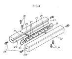
- a device proposed as disclosed in Published Unexamined Utility Model Application No. 4-88523 is a finite linear motion device comprising a first rail 21 in which is formed a first rolling groove 21a having a transverse V-shaped cross section, a second rail 22 disposed facing the first rail 21 and provided with a second rolling groove 22a having a transverse V-shaped cross section, a plurality of rolling bodies 24 that are disposed in a rolling path 23 formed by the rolling grooves 21a, 22a of the facing first rail 21 and second rail 22 and that roll over the rolling path 23, and a holding device 26 for rollably holding the rolling bodies 24 at predetermined intervals.
- pulleys 25 are provided to end parts of the holding device 26, and a wire 27 connected to an anchoring plate 29 provided to the rails 21, 22 is pulled toward the pulleys 25.
- the holding device 26 is suspended and made to move in conjunction with the movement of the rails 21, 22, and the holding device 26 is prevented from deviating (referred to below as "the conventional example of the art"; shown in FIG. 1 ).
- the reference symbol 28 indicates a stopper screw for stopping the fall of the holding device 26, and the reference symbol 30 indicates a screw for anchoring the anchoring plate 29 to the rails 21, 22.
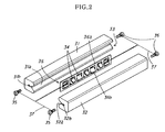
- the invention according to Patent Document 2 is a finite linear motion device comprising a first rail 31 in which a first rolling groove 31a is formed; a second rail 32 disposed facing the first rail 31 and provided with a second rolling groove 32a; a plurality of rolling bodies 34 that is disposed in a rolling path 33 formed by the rolling grooves 31a, 32a of the facing first rail 31 and second rail 32, and that rolls over the rolling path 33; and a holding device 36 for rollably holding the rolling bodies 34 at predetermined intervals.
- an end of a cord 37 of a predetermined length is connected to a distal end part of the first rail 31; the other end of the cord 37 is extended to and slidably wrapped around the rolling body 34 held at a distal end side of the holding device 36 and is connected to a distal end part of the second rail 32; an end of another cord 37 of a predetermined length is connected to a proximal end part of the first rail 31; and the other end of the cord 37 is extended to and slidably wrapped around the rolling body 34 held on a proximal end side of the holding device 36, and is connected to a proximal end part of the second rail 32.
- reference symbols 31b and 32b indicate screw holes into which are screwed stopper screws 35, and ends of the cord 37 are wrapped around the stopper screws;
- reference symbol 36a indicates a plate body, and the reference symbol 36b indicates windows in which the rolling bodies 34 are held.
- the present invention was devised in view of the foregoing circumstances, and it is an object thereof to provide a finite linear motion device that has an uncomplicated configuration and that has exceptional utility.
- a holding device can be prevented from deviating, a compact design can be employed without hindering smooth travel, a cord is not readily worn, and durability is correspondingly improved.
- the present invention provides a finite linear motion device comprising a first rail 1 provided with a first rolling groove 1a, a second rail 2 disposed facing the first rail 1 and provided with a second rolling groove 2a, a plurality of rolling bodies 4 that is disposed in a rolling path 3 formed by the rolling grooves 1a, 2a of the facing first rail 1 and second rail 2 and that rolls over the rolling path 3, and a holding device 5 for rollably holding the rolling bodies 4 at predetermined intervals; wherein one end of a cord 6 of a predetermined length is connected to a distal end part of the first rail 1; the other end of the cord 6 is extended to and slidably wrapped around a first rotating body 7 that is rotatably provided at a position near a center of the holding device 5 in a length direction, and is connected to a distal end part of the second rail 2; an end of another cord 6 of a predetermined length is connected to a proximal end part of the first rail 1; another end of the other cord 6 is extended to and
- a finite linear motion device is provided in which, in the finite linear motion device according to the first aspect, the first rotating body 7 and second rotating body 8 are disposed alongside each other in the length direction of the holding device 5.
- a finite linear motion device is provided in which, in the finite linear motion device according to the second aspect, the first rotating body 7 and second rotating body 8 are provided to a substantially center part of the holding device 5.
- a finite linear motion device in which, in the finite linear device according to any of the first through third aspects, the first rotating body 7 and second rotating body 8 are provided in a substantially bilateral symmetric relationship on either side of a center point of the holding device 5 in the length direction.
- a finite linear motion device in which, in the finite linear device according to any of the first through fourth aspects, the first rolling groove 1a and second rolling groove 2a are formed so as to be v-shaped in cross-section.
- a finite linear motion device in which, in the finite linear device according to the fifth aspect, clearance concavities 1c, 2c for providing clearance relative to a grinding body that grinds the first rolling groove 1a or second rolling groove 2a is provided to bottom parts of the first rolling groove 1a and second rolling grove 2a; and outer peripheral parts of the first rotating body 7 and the second rotating body 8, and cords 6 are disposed in the clearance concavities 1c, 2c.
- the present invention provides a finite linear motion device that has an uncomplicated configuration and has extremely exceptional utility.
- a holding device can be prevented from deviating, a compact design can be employed without hindering smooth travel, a cord is not readily worn, and durability is correspondingly improved.
- a holding device 5 When a first rail 1 is moved relative to a second rail 2, a holding device 5 is forcibly moved by a first rotating body 7 held by the holding device 5 and a cord 6 of a predetermined length that is wrapped around a second rotating body 8.
- the amount that the holding device is moved is restricted to 1/2 the amount that the first rail 1 and second rail 2 move. Therefore, deviation between the first and second rails 1, 2 and the holding device 5 is prevented.
- the cord 6 is wrapped around the first rotating body 7 and second rotating body 8 that rotate independently of the rolling bodies 4 (independent of the movement of the rails 1, 2). Therefore, the problems that arise in Patent Document 2 do not occur (the cord 37 of Patent Document 2 is wrapped around the rolling bodies 34, which rotate in conjunction with the movement of the rails 31, 32). Therefore, friction does not readily arise between the first and second rotating bodies 7, 8 and the cord 6, and wearing of the cord 6 is correspondingly minimized.
- the first rotating body 7 and the second rotating body 8 are provided to positions near a center of the holding device 5.
- At least two or more rolling bodies 4 can be provided to the holding device in each of the area between the first rotating body 7 and the distal end part of the holding device 5 and the area between the second rotating body 8 and the proximal end part of the holding device 5.
- a moment load can thereby be borne by the rolling bodies 4 positioned at both ends of the holding device 5 even when the first rail 1 and second rail 2 are moved in a mutually relative fashion and the rails 1, 2 are both placed in a substantially cantilevered state.
- the rotating body (pulley) is provided to both ends of the holding device rather than to a center of the holding device and the pulley is pulled toward an interior of the rails
- the pulley cannot bear a load as the rolling bodies can. Therefore, the amount of displacement under load is greater than in the present invention (the amount of displacement under load at a position near the end parts of the holding device decreases to the extent that the load can be borne by the rolling bodies).
- the first rotating body 7 and the second rotating body 8 are provided to positions near the center of the holding device 5. Therefore, rolling bodies for bearing a load can be provided to end parts of the holding device, displacement under load is low, the moment load can favorably be borne, deviation is minimized in the holding device, and the first rail and second rail can favorably be moved in mutually relative fashion.
- the present invention is a finite linear motion device in which the holding device can be properly moved without a rack and pinion being provided, smooth travel can be achieved, and a compact design can be employed. Furthermore, the cord is not readily worn and exceptional durability is correspondingly obtained.
- the present example is a finite linear motion device comprising a first rail 1 in which a first rolling groove 1a is formed, a second rail 2 disposed facing the first rail 1 and provided with a second rolling groove 2a, a plurality of rolling bodies 4 that is disposed in a rolling path 3 formed by the rolling grooves 1a, 2a of the facing first rail 1 and second rail 2 and that rolls over the rolling path 3, and a holding device 5 for rollably holding the rolling bodies 4 at predetermined intervals; wherein one end of a cord 6 of a predetermined length is connected to a distal end part of the first rail 1; the other end of the cord 6 is extended to and slidably wrapped around a first rotating body 7 that is rotatably provided at a position near a center of the holding device 5 in a length direction, and is connected to a distal end part of the second rail 2; an end of a cord 6 of a predetermined length is connected to a proximal end part of the first rail 1; the other end of the cord 6 is extended
- the first rail 1 and second rail 2 are metallic bodies that are substantially square-shaped in cross section.
- the rolling grooves 1a, 2a that are transversely V-shaped in cross section extend in a longitudinal direction on facing inner surfaces of the first rail 1 and second rail 2.
- the facing rolling grooves 1a, 2a form the rolling path 3 that is rhombus-shaped in cross section and in which the rolling bodies 4 are disposed.
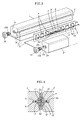
- Clearance concavities 1c, 2c for providing clearance relative to a grinding body (grindstone) when the grinding body is used to grind (finish) wall surfaces of the rolling grooves 1a, 2a (downward-facing surfaces and upward-facing surfaces in FIG. 3 ) are formed on bottom parts of the cross-sectionally transverse V-shaped rolling grooves 1a, 2a.
- a plurality of the rolling bodies 4 is disposed in linear fashion in the rolling path 3 in a state of being held by the holding device 5.
- cylindrical objects are used for the rolling bodies 4.
- the rolling bodies 4 are held by the holding device 5 in a state in which adjacent rolling bodies 4 and axial centers thereof are tilted 90 degrees from one another.
- the holding device 5 is configured so that a plurality of windows 5b for holding the rolling bodies 4 is formed on a plate body 5a.
- the rolling bodies 4 make contact with inner edges of the windows 5b and are held.
- the first rotating body 7 and the second rotating body 8 are provided to the center part of the holding device 5 in linear fashion so as to be on either side of a center point of the holding device 5 in the length direction.
- the first rotating body 7, second rotating body 8, and rolling bodies 4 are provided in a substantially bilaterally symmetrical fashion on either side of the center point of the holding device 5 in the length direction.
- the holding device 5 is configured so that three of the rolling bodies 4 are provided each to the area between the first rotating body 7 and the distal end part of the holding device 5, and to the area between the second rotating body 8 and the proximal end part of the holding device 5.
- the holding device 5 may be configured so that the positions of the first and second rotating bodies 7, 8 and the positions of the rolling bodies 4 on the innermost sides in FIG. 3 are switched so that the rolling bodies 4 are disposed between the rotating bodies 7, 8.
- a configuration may alternatively be employed in which a rolling body is added between the rotating bodies 7, 8 so that the rolling body 4 is disposed between the rotating bodies 7, 8.
- resin pulleys are used for the rotating bodies 7, 8. These pulleys are rotatably provided via an axle 11 inserted into a shaft hole 12 that is provided to a laterally dividable resin holder 9. The holder 9 is anchored to the windows 5d of the holding device 5.
- a groove 13 in which the cord 6 (metallic wire) is disposed is formed on outer peripheral parts of the rotating bodies 7, 8.
- the radius and width of the rotating bodies 7, 8 are set so that the rotating bodies will be accommodated in the clearance concavities 1c, 2c as shown in FIG. 4 so that the cord 6 and the outer peripheral parts in which the groove 13 is formed will not interfere with the rolling bodies 4.
- two cords 6 are attached to the rotating bodies 7, 8, and the cords 6 can be wound and unwound in accordance with the movement of the rolling bodies 4, instead of one cord 6 being wrapped around the rotating bodies.
- Such a configuration will result in the same action and effect as the above-described present example.
- the length of the cords 6 is set so that, e.g., the cord 6 on a front side (movement direction side) of the holding device 5 is tightened when the holding device 5 moves less than 1/2 the amount that the first rail 1 moves, and the rolling bodies 4 are pulled forward by the tightening action, whereby the holding device 5 is forcibly pulled forward.
- the cord 6 on the rear side of the holding device 5 (the side opposite the moving direction) is tightened when the holding device 5 moves more than 1/2 the amount that the first rail 1 moves, and the rolling bodies 4 are pulled rearward by the tightening action, whereby the holding device 5 is forcibly pulled rearward.
- the cords 6 should be suitably set to a length at which partial slackness (excessive length) is avoided and at which the movement of the rolling bodies 4 is not hindered (excessively short) so that the above-described action can be produced.
- Stopper screws 10 for stopping the holding device 5 from falling are provided to end surfaces of the first rail 1 and second rail 2.
- the stopper screws 10 anchor the end parts of the cords 6 to the end parts of the first rail 1 and second rail 2. Specifically, one end of each of the cords 6 is wrapped around the male screw part 10a of the corresponding stopper screws 10, and the male screw parts 10a are screwed into female screw parts 1b, 2b provided to the end surfaces of the first rail 1 and second rail 2. Therefore, a special screw or other implement for anchoring the cords 6 is not necessary, and the configuration is correspondingly made less complex.
- the holding device 5 is forcibly moved by the first rotating body 7 held by the holding device 5 and by the cords 6 of a predetermined length wrapped around the second rotating body 8. Deviation between the first and second rail 1 and second rail 2 and the holding device 5 is prevented because the amount that the holding device moves is restricted to 1/2 the amount that the first rail 1 and second rail 2 move.
- the cords 6 are wrapped around the first rotating body 7 and second rotating body 8, which rotate independently of the rolling bodies 4. Therefore, the problems arising in Patent Document 2 do not occur. Consequently, friction does not readily occur between the first and second rotating bodies 7, 8 and the cords 6, and wearing of the cords 6 is correspondingly reduced.
- the first rotating body 7 and the second rotating body 8 are provided at positions near the center of the holding device 5 in which two or more of the rolling bodies 4 can be provided between the first and second rotating bodies 7, 8 and both ends of the holding device 5.
- a moment load can thereby be borne by the rolling bodies 4 positioned at both sides of the holding device 5 even when the first rail 1 and second rail 2 are moved relative to one another and the rails 1, 2 are both placed in a substantially cantilevered state. There is therefore a decrease in the displacement of the rails 1, 2 under load; and pitching, yawing, and rolling decrease during travel.
- first rolling groove 1a and second rolling groove 2a are formed to be transversely V-shaped in cross-section
- the clearance concavities 1c, 2c for providing clearance relative to the grinding body that grinds the first rolling groove 1a or second rolling groove 2a are provided to the bottom parts of the first and second rolling grooves
- the cords 6 and the outer peripheral parts of the first rotating body 7 and second rotating body 8 are disposed in the clearance concavities 1c, 2c, respectively. Therefore, the first rotating body 7, second rotating body 8, and cords 6 can be readily disposed without any interference with other members by using the clearance concavities 1c, 2c, which are necessary in the formation of the first rolling groove 1a and second rolling groove 2a.
- the present example is a finite linear motion device in which the holding device can be properly moved without a rack and pinion being provided, smooth travel can be achieved; a compact design can be employed. Furthermore, the cord is not readily worn and exceptional durability is correspondingly obtained.
Landscapes
- Engineering & Computer Science (AREA)
- General Engineering & Computer Science (AREA)
- Mechanical Engineering (AREA)
- Bearings For Parts Moving Linearly (AREA)
Abstract
Description
- The present invention relates to a finite linear motion device.
- In a finite linear motion device proposed in the conventional art and comprising a pair of rails provided with rolling grooves, a plurality of rolling bodies disposed in a rolling path formed by the rolling grooves between the rails, and a holding device for holding the rolling bodies at predetermined intervals, the holding device is formed separately from the rails and does not move in conjunction with the rails. Therefore, the movement of the rails and the movement of the holding device are different. When a reciprocating linear movement is repeatedly made, the holding device and stopper screws on both end parts of the rolling path make mutual contact or another such incident occurs, and problems arise in that a highly precise linear motion cannot be made and a predetermined stroke cannot be achieved.
- Therefore, a configuration has recently been proposed in which a pinion is mounted on a center part of the holding device and the holding device is prevented from deviating by the use of a so-called rack and pinion system in which a rack is provided to a rail.
- A device proposed as disclosed in Published Unexamined Utility Model Application No.
4-88523 first rail 21 in which is formed a first rolling groove 21a having a transverse V-shaped cross section, asecond rail 22 disposed facing thefirst rail 21 and provided with a second rollinggroove 22a having a transverse V-shaped cross section, a plurality ofrolling bodies 24 that are disposed in arolling path 23 formed by therolling grooves 21a, 22a of the facingfirst rail 21 andsecond rail 22 and that roll over therolling path 23, and aholding device 26 for rollably holding therolling bodies 24 at predetermined intervals. In the finite linear motion device,pulleys 25 are provided to end parts of theholding device 26, and awire 27 connected to ananchoring plate 29 provided to therails pulleys 25. As a result, theholding device 26 is suspended and made to move in conjunction with the movement of therails holding device 26 is prevented from deviating (referred to below as "the conventional example of the art"; shown inFIG. 1 ). In the drawing, thereference symbol 28 indicates a stopper screw for stopping the fall of theholding device 26, and thereference symbol 30 indicates a screw for anchoring theanchoring plate 29 to therails - However, according to such a rack and pinion system, a problem arises in that contact (friction) between the component parts dramatically hinders smooth travel.
- In the conventional example of the art, when the pulley is placed in an interior of the rails, the number of rolling bodies must be reduced. As a result, the ability to bear a load will inevitably decline. When the pulley is provided to an exterior of the rails, the pulleys make strokes along with the holding device. Therefore, a space through which the pulley moves must be maintained, and a problem arises in that the device must be correspondingly increased in size.
- Therefore, the present inventors have proposed an invention according to
Patent Document 2 that resolves the foregoing problems. - As shown in
FIG. 2 , the invention according toPatent Document 2 is a finite linear motion device comprising afirst rail 31 in which a firstrolling groove 31a is formed; asecond rail 32 disposed facing thefirst rail 31 and provided with a secondrolling groove 32a; a plurality ofrolling bodies 34 that is disposed in arolling path 33 formed by therolling grooves first rail 31 andsecond rail 32, and that rolls over therolling path 33; and aholding device 36 for rollably holding therolling bodies 34 at predetermined intervals. In the finite linear motion device, an end of acord 37 of a predetermined length is connected to a distal end part of thefirst rail 31; the other end of thecord 37 is extended to and slidably wrapped around therolling body 34 held at a distal end side of theholding device 36 and is connected to a distal end part of thesecond rail 32; an end of anothercord 37 of a predetermined length is connected to a proximal end part of thefirst rail 31; and the other end of thecord 37 is extended to and slidably wrapped around therolling body 34 held on a proximal end side of theholding device 36, and is connected to a proximal end part of thesecond rail 32. In the drawing,reference symbols stopper screws 35, and ends of thecord 37 are wrapped around the stopper screws; thereference symbol 36a indicates a plate body, and thereference symbol 36b indicates windows in which therolling bodies 34 are held. - [Patent Document 1] Published Unexamined Utility Model Application No.
4-88523 - [Patent Document 2] Utility Model Registration No.
3109085 - However, the present inventors conducted further research and studies, resulting in a conclusion that, in the invention according to
Patent Document 2, because thecord 37 is wrapped around the concave groove provided to therotating bodies 34 that rotate in conjunction with the movement of theholding device 36, deviation occurs between rotational dimensions of a large-sized part that comes into contact with transfer surfaces of the rolling bodies 34 (distance over which thecord 37 moves) and rotational dimensions of a bottom part of the concave groove with which thecord 37 comes into contact (small-sized part). Thecord 37 slackens, the ability of the cord to prevent the holding device from deviating declines or friction occurs between the cord and the holding device, thecord 37 is subjected to wear in a relatively short period of time, and the lifespan of thecord 37 may correspondingly decrease. - The present invention was devised in view of the foregoing circumstances, and it is an object thereof to provide a finite linear motion device that has an uncomplicated configuration and that has exceptional utility. In this device, a holding device can be prevented from deviating, a compact design can be employed without hindering smooth travel, a cord is not readily worn, and durability is correspondingly improved.
- A summary of the present invention shall be given with reference to the accompanying drawings.
- The present invention provides a finite linear motion device comprising a first rail 1 provided with a first rolling groove 1a, a
second rail 2 disposed facing the first rail 1 and provided with a secondrolling groove 2a, a plurality ofrolling bodies 4 that is disposed in arolling path 3 formed by therolling grooves 1a, 2a of the facing first rail 1 andsecond rail 2 and that rolls over therolling path 3, and aholding device 5 for rollably holding therolling bodies 4 at predetermined intervals; wherein one end of acord 6 of a predetermined length is connected to a distal end part of the first rail 1; the other end of thecord 6 is extended to and slidably wrapped around a first rotatingbody 7 that is rotatably provided at a position near a center of theholding device 5 in a length direction, and is connected to a distal end part of thesecond rail 2; an end of anothercord 6 of a predetermined length is connected to a proximal end part of the first rail 1; another end of theother cord 6 is extended to and slidably wrapped around a second rotatingbody 8 that is rotatably provided at a position near a center of theholding device 5 in the length direction, and is connected to a proximal end part of thesecond rail 2; and at least two or more of therotating bodies 4 are provided between the first rotatingbody 7 and the distal end part of theholding device 5, and between the second rotatingbody 8 and the proximal end part of theholding device 5. - A finite linear motion device is provided in which, in the finite linear motion device according to the first aspect, the first
rotating body 7 and secondrotating body 8 are disposed alongside each other in the length direction of theholding device 5. - A finite linear motion device is provided in which, in the finite linear motion device according to the second aspect, the first
rotating body 7 and second rotatingbody 8 are provided to a substantially center part of theholding device 5. - A finite linear motion device is provided in which, in the finite linear device according to any of the first through third aspects, the first
rotating body 7 and secondrotating body 8 are provided in a substantially bilateral symmetric relationship on either side of a center point of theholding device 5 in the length direction. - A finite linear motion device is provided in which, in the finite linear device according to any of the first through fourth aspects, the first rolling groove 1a and second
rolling groove 2a are formed so as to be v-shaped in cross-section. - A finite linear motion device is provided in which, in the finite linear device according to the fifth aspect,
clearance concavities 1c, 2c for providing clearance relative to a grinding body that grinds the first rolling groove 1a or secondrolling groove 2a is provided to bottom parts of the first rolling groove 1a and second rollinggrove 2a; and outer peripheral parts of the first rotatingbody 7 and the second rotatingbody 8, andcords 6 are disposed in theclearance concavities 1c, 2c. - When configured in the above-described manner, the present invention provides a finite linear motion device that has an uncomplicated configuration and has extremely exceptional utility. In this device, a holding device can be prevented from deviating, a compact design can be employed without hindering smooth travel, a cord is not readily worn, and durability is correspondingly improved.
-
-
FIG. 1 is a perspective view schematically showing a conventional example of the art in an exploded state; -
FIG. 2 is a perspective view schematically showing a conventional example of the art in an exploded state; -
FIG. 3 is a perspective view schematically showing the present example in an exploded state; and -
FIG. 4 is a cross-sectional view schematically showing components of the present example in an enlarged state. - Preferred embodiments of the present invention shall be described in simple terms by illustrating operations of the present invention with reference to the drawings.
- When a first rail 1 is moved relative to a
second rail 2, aholding device 5 is forcibly moved by a first rotatingbody 7 held by theholding device 5 and acord 6 of a predetermined length that is wrapped around a second rotatingbody 8. The amount that the holding device is moved is restricted to 1/2 the amount that the first rail 1 andsecond rail 2 move. Therefore, deviation between the first andsecond rails 1, 2 and theholding device 5 is prevented. - The
cord 6 is wrapped around the first rotatingbody 7 and second rotatingbody 8 that rotate independently of the rolling bodies 4 (independent of the movement of the rails 1, 2). Therefore, the problems that arise inPatent Document 2 do not occur (thecord 37 ofPatent Document 2 is wrapped around therolling bodies 34, which rotate in conjunction with the movement of therails 31, 32). Therefore, friction does not readily arise between the first and secondrotating bodies cord 6, and wearing of thecord 6 is correspondingly minimized. - The first rotating
body 7 and the second rotatingbody 8 are provided to positions near a center of theholding device 5. At least two or morerolling bodies 4 can be provided to the holding device in each of the area between the first rotatingbody 7 and the distal end part of theholding device 5 and the area between the second rotatingbody 8 and the proximal end part of theholding device 5. A moment load can thereby be borne by therolling bodies 4 positioned at both ends of theholding device 5 even when the first rail 1 andsecond rail 2 are moved in a mutually relative fashion and therails 1, 2 are both placed in a substantially cantilevered state. Therefore, in instances where therails 1, 2 are displaced by only a small amount under load, pitching (wobbling in a longitudinal direction relative to the travel direction), yawing (wobbling in a lateral direction relative to the travel direction), and rolling (wobbling in a rotation direction relative to the travel direction) decrease during travel. - For example, in instances such as in the invention disclosed in Patent Document 1, where the rotating body (pulley) is provided to both ends of the holding device rather than to a center of the holding device and the pulley is pulled toward an interior of the rails, the pulley cannot bear a load as the rolling bodies can. Therefore, the amount of displacement under load is greater than in the present invention (the amount of displacement under load at a position near the end parts of the holding device decreases to the extent that the load can be borne by the rolling bodies). In the present invention, the first rotating
body 7 and the second rotatingbody 8 are provided to positions near the center of theholding device 5. Therefore, rolling bodies for bearing a load can be provided to end parts of the holding device, displacement under load is low, the moment load can favorably be borne, deviation is minimized in the holding device, and the first rail and second rail can favorably be moved in mutually relative fashion. - Therefore, the present invention is a finite linear motion device in which the holding device can be properly moved without a rack and pinion being provided, smooth travel can be achieved, and a compact design can be employed. Furthermore, the cord is not readily worn and exceptional durability is correspondingly obtained.
- Specific examples of the present invention shall be described with reference to
FIGS. 3 and 4 . - The present example is a finite linear motion device comprising a first rail 1 in which a first rolling groove 1a is formed, a
second rail 2 disposed facing the first rail 1 and provided with a second rollinggroove 2a, a plurality ofrolling bodies 4 that is disposed in arolling path 3 formed by therolling grooves 1a, 2a of the facing first rail 1 andsecond rail 2 and that rolls over therolling path 3, and aholding device 5 for rollably holding therolling bodies 4 at predetermined intervals; wherein one end of acord 6 of a predetermined length is connected to a distal end part of the first rail 1; the other end of thecord 6 is extended to and slidably wrapped around a first rotatingbody 7 that is rotatably provided at a position near a center of theholding device 5 in a length direction, and is connected to a distal end part of thesecond rail 2; an end of acord 6 of a predetermined length is connected to a proximal end part of the first rail 1; the other end of thecord 6 is extended to and slidably wrapped around a second rotatingbody 8 that is rotatably provided at a position near a center of theholding device 5 in the length direction, and is connected to a proximal end part of thesecond rail 2; and at least two or more of therotating bodies 4 are provided between the first rotatingbody 7 and the distal end part of theholding device 5, and between the second rotatingbody 8 and the proximal end part of theholding device 5. - The parts shall be described specifically.
- The first rail 1 and
second rail 2 are metallic bodies that are substantially square-shaped in cross section. Therolling grooves 1a, 2a that are transversely V-shaped in cross section extend in a longitudinal direction on facing inner surfaces of the first rail 1 andsecond rail 2. The facing rollinggrooves 1a, 2a form the rollingpath 3 that is rhombus-shaped in cross section and in which the rollingbodies 4 are disposed. -
Clearance concavities 1c, 2c for providing clearance relative to a grinding body (grindstone) when the grinding body is used to grind (finish) wall surfaces of the rollinggrooves 1a, 2a (downward-facing surfaces and upward-facing surfaces inFIG. 3 ) are formed on bottom parts of the cross-sectionally transverse V-shaped rollinggrooves 1a, 2a. - A plurality of the rolling
bodies 4 is disposed in linear fashion in the rollingpath 3 in a state of being held by the holdingdevice 5. - Specifically, cylindrical objects are used for the rolling
bodies 4. The rollingbodies 4 are held by the holdingdevice 5 in a state in whichadjacent rolling bodies 4 and axial centers thereof are tilted 90 degrees from one another. - The holding
device 5 is configured so that a plurality ofwindows 5b for holding the rollingbodies 4 is formed on aplate body 5a. The rollingbodies 4 make contact with inner edges of thewindows 5b and are held. - The first
rotating body 7 and the secondrotating body 8 are provided to the center part of the holdingdevice 5 in linear fashion so as to be on either side of a center point of the holdingdevice 5 in the length direction. The firstrotating body 7, secondrotating body 8, and rollingbodies 4 are provided in a substantially bilaterally symmetrical fashion on either side of the center point of the holdingdevice 5 in the length direction. In the present example, the holdingdevice 5 is configured so that three of the rollingbodies 4 are provided each to the area between the firstrotating body 7 and the distal end part of the holdingdevice 5, and to the area between the secondrotating body 8 and the proximal end part of the holdingdevice 5. - In the present example, a configuration has been adopted in which the
rotating bodies device 5. However, for example, the holdingdevice 5 may be configured so that the positions of the first and secondrotating bodies bodies 4 on the innermost sides inFIG. 3 are switched so that the rollingbodies 4 are disposed between therotating bodies rotating bodies body 4 is disposed between therotating bodies - Specifically, resin pulleys are used for the
rotating bodies axle 11 inserted into ashaft hole 12 that is provided to a laterallydividable resin holder 9. Theholder 9 is anchored to thewindows 5d of the holdingdevice 5. - A
groove 13 in which the cord 6 (metallic wire) is disposed is formed on outer peripheral parts of therotating bodies rotating bodies clearance concavities 1c, 2c as shown inFIG. 4 so that thecord 6 and the outer peripheral parts in which thegroove 13 is formed will not interfere with the rollingbodies 4. - In the present example, a configuration is adopted wherein one cord is extended to each of the
rotating bodies bodies cords 6 are wrapped around the firstrotating body 7 and secondrotating body 8 in a tightened state. - In an alternative configuration, two
cords 6 are attached to therotating bodies cords 6 can be wound and unwound in accordance with the movement of the rollingbodies 4, instead of onecord 6 being wrapped around the rotating bodies. Such a configuration will result in the same action and effect as the above-described present example. - In the present example, the length of the
cords 6 is set so that, e.g., thecord 6 on a front side (movement direction side) of the holdingdevice 5 is tightened when the holdingdevice 5 moves less than 1/2 the amount that the first rail 1 moves, and the rollingbodies 4 are pulled forward by the tightening action, whereby the holdingdevice 5 is forcibly pulled forward. On the other hand, thecord 6 on the rear side of the holding device 5 (the side opposite the moving direction) is tightened when the holdingdevice 5 moves more than 1/2 the amount that the first rail 1 moves, and the rollingbodies 4 are pulled rearward by the tightening action, whereby the holdingdevice 5 is forcibly pulled rearward. - In other words, the
cords 6 should be suitably set to a length at which partial slackness (excessive length) is avoided and at which the movement of the rollingbodies 4 is not hindered (excessively short) so that the above-described action can be produced. - Stopper screws 10 for stopping the holding
device 5 from falling are provided to end surfaces of the first rail 1 andsecond rail 2. - The stopper screws 10 anchor the end parts of the
cords 6 to the end parts of the first rail 1 andsecond rail 2. Specifically, one end of each of thecords 6 is wrapped around themale screw part 10a of the corresponding stopper screws 10, and themale screw parts 10a are screwed intofemale screw parts 1b, 2b provided to the end surfaces of the first rail 1 andsecond rail 2. Therefore, a special screw or other implement for anchoring thecords 6 is not necessary, and the configuration is correspondingly made less complex. - Since the present example is configured in the above-described manner, when the first rail 1 is moved relative to the
second rail 2, the holdingdevice 5 is forcibly moved by the firstrotating body 7 held by the holdingdevice 5 and by thecords 6 of a predetermined length wrapped around the secondrotating body 8. Deviation between the first and second rail 1 andsecond rail 2 and the holdingdevice 5 is prevented because the amount that the holding device moves is restricted to 1/2 the amount that the first rail 1 andsecond rail 2 move. - The
cords 6 are wrapped around the firstrotating body 7 and secondrotating body 8, which rotate independently of the rollingbodies 4. Therefore, the problems arising inPatent Document 2 do not occur. Consequently, friction does not readily occur between the first and secondrotating bodies cords 6, and wearing of thecords 6 is correspondingly reduced. - The first
rotating body 7 and the secondrotating body 8 are provided at positions near the center of the holdingdevice 5 in which two or more of the rollingbodies 4 can be provided between the first and secondrotating bodies device 5. A moment load can thereby be borne by the rollingbodies 4 positioned at both sides of the holdingdevice 5 even when the first rail 1 andsecond rail 2 are moved relative to one another and therails 1, 2 are both placed in a substantially cantilevered state. There is therefore a decrease in the displacement of therails 1, 2 under load; and pitching, yawing, and rolling decrease during travel. - For example, as disclosed in Patent Document 1, when the rotating bodies (pulleys) are provided to both ends of the holding device rather than to the center of the holding device, and the pulleys are pulled toward the interior of the rails, the pulleys cannot bear a load as the rolling bodies can. Therefore, displacement under load is greater than in the present invention (displacement under load at a position near the end parts of the holding device is reduced to a point where the load can be borne). In the present invention, the rolling bodies for bearing the load are situated further toward the end parts of the holding device and can favorably bear a moment load. Accordingly, displacement under load is low, deviation in the holding device is minimized, and the first rail and second rail can be favorably moved relative to one another.
- In addition, a configuration is adopted in which the first rolling groove 1a and second rolling
groove 2a are formed to be transversely V-shaped in cross-section, theclearance concavities 1c, 2c for providing clearance relative to the grinding body that grinds the first rolling groove 1a or second rollinggroove 2a are provided to the bottom parts of the first and second rolling grooves, and thecords 6 and the outer peripheral parts of the firstrotating body 7 and secondrotating body 8 are disposed in theclearance concavities 1c, 2c, respectively. Therefore, the firstrotating body 7, secondrotating body 8, andcords 6 can be readily disposed without any interference with other members by using theclearance concavities 1c, 2c, which are necessary in the formation of the first rolling groove 1a and second rollinggroove 2a. - Therefore, the present example is a finite linear motion device in which the holding device can be properly moved without a rack and pinion being provided, smooth travel can be achieved; a compact design can be employed. Furthermore, the cord is not readily worn and exceptional durability is correspondingly obtained.
Claims (6)
- A finite linear motion device comprising a first rail provided with a first rolling groove, a second rail disposed facing the first rail and provided with a second rolling groove, a plurality of rolling bodies that is disposed in a rolling path formed by the rolling grooves of the facing first rail and second rail and that rolls over the rolling path, and a holding device for rollably holding the rolling bodies at predetermined intervals; wherein
one end of a cord of a predetermined length is connected to a distal end part of the first rail; the other end of the cord is extended to and slidably wrapped around a first rotating body that is rotatably provided at a position near a center of the holding device in a length direction, and is connected to a distal end part of the second rail;
an end of another cord of a predetermined length is connected to a proximal end part of the first rail; another end of the other cord is extended to and slidably wrapped around a second rotating body that is rotatably provided at a position near a center of the holding device in the length direction, and is connected to a proximal end part of the second rail; and
at least two or more of the rotating bodies are provided between the first rotating body and the distal end part of the holding device, and between the second rotating body and the proximal end part of the holding device. - The finite linear motion device according to claim 1, wherein the first rotating body and second rotating body are disposed alongside each other in the length direction of the holding device.
- The finite linear motion device according to claim 2, wherein the first rotating body and second rotating body are provided to a substantially center part of the holding device.
- The finite linear motion device according to any of claims 1 through 3, wherein the first rotating body and second rotating body are provided in a substantially bilateral symmetric relationship on either side of a center point of the holding device in the length direction.
- The finite linear motion device according to any of claims 1 through 4, wherein the first rolling groove and second rolling groove are formed so as to be V-shaped in cross-section.
- The finite linear motion device according to claim 5, wherein
clearance concavities for offering relief from a grinding body that grinds the first rolling groove or second rolling groove is provided to bottom parts of the first rolling groove and second rolling grove; and
outer peripheral parts of the first rotating body and the second rotating body, and the cords are disposed in the clearance concavities.
Applications Claiming Priority (1)
| Application Number | Priority Date | Filing Date | Title |
|---|---|---|---|
| JP2007071254A JP4053580B1 (en) | 2007-03-19 | 2007-03-19 | Finite linear motion device |
Publications (2)
| Publication Number | Publication Date |
|---|---|
| EP1972805A2 true EP1972805A2 (en) | 2008-09-24 |
| EP1972805A3 EP1972805A3 (en) | 2009-07-01 |
Family
ID=38330028
Family Applications (1)
| Application Number | Title | Priority Date | Filing Date |
|---|---|---|---|
| EP07011663A Withdrawn EP1972805A3 (en) | 2007-03-19 | 2007-06-14 | Finite linear motion device |
Country Status (2)
| Country | Link |
|---|---|
| EP (1) | EP1972805A3 (en) |
| JP (1) | JP4053580B1 (en) |
Cited By (1)
| Publication number | Priority date | Publication date | Assignee | Title |
|---|---|---|---|---|
| CN105156472A (en) * | 2015-08-17 | 2015-12-16 | 热川精密机械(昆山)有限公司 | Linear guide rail |
Families Citing this family (2)
| Publication number | Priority date | Publication date | Assignee | Title |
|---|---|---|---|---|
| JP5208832B2 (en) * | 2009-03-31 | 2013-06-12 | 日本トムソン株式会社 | Finite linear motion guide unit equipped with cage slip prevention mechanism |
| KR101092978B1 (en) | 2009-10-12 | 2011-12-12 | (주)원에스티 | Linear motion guide unit |
Citations (2)
| Publication number | Priority date | Publication date | Assignee | Title |
|---|---|---|---|---|
| JPH03109085U (en) | 1990-02-16 | 1991-11-08 | ||
| JPH0488523U (en) | 1990-12-20 | 1992-07-31 |
Family Cites Families (7)
| Publication number | Priority date | Publication date | Assignee | Title |
|---|---|---|---|---|
| CH280851A (en) * | 1949-11-30 | 1952-02-15 | Paillard Sa | Device for guiding a mobile assembly on a fixed support. |
| CH288636A (en) * | 1949-11-30 | 1953-01-31 | Paillard Sa | Device for guiding a mobile assembly on a fixed support. |
| JP2628377B2 (en) * | 1989-06-19 | 1997-07-09 | 日本トムソン株式会社 | Thin-walled finite linear motion guide unit with cage displacement prevention device |
| US5116141A (en) * | 1990-11-01 | 1992-05-26 | Anwar Chitayat | Anti-creep for bearing retainers |
| JP2540163Y2 (en) * | 1990-12-20 | 1997-07-02 | 日本トムソン株式会社 | Thin-walled finite linear motion guide unit |
| US5251984A (en) * | 1991-12-20 | 1993-10-12 | Nippon Thompson Co., Ltd. | Linear motion guide unit having a synchronized retainer |
| JP2001165160A (en) * | 1999-09-30 | 2001-06-19 | Nikon Corp | Linear guide device |
-
2007
- 2007-03-19 JP JP2007071254A patent/JP4053580B1/en active Active
- 2007-06-14 EP EP07011663A patent/EP1972805A3/en not_active Withdrawn
Patent Citations (2)
| Publication number | Priority date | Publication date | Assignee | Title |
|---|---|---|---|---|
| JPH03109085U (en) | 1990-02-16 | 1991-11-08 | ||
| JPH0488523U (en) | 1990-12-20 | 1992-07-31 |
Cited By (1)
| Publication number | Priority date | Publication date | Assignee | Title |
|---|---|---|---|---|
| CN105156472A (en) * | 2015-08-17 | 2015-12-16 | 热川精密机械(昆山)有限公司 | Linear guide rail |
Also Published As
| Publication number | Publication date |
|---|---|
| JP4053580B1 (en) | 2008-02-27 |
| JP2008232232A (en) | 2008-10-02 |
| EP1972805A3 (en) | 2009-07-01 |
Similar Documents
| Publication | Publication Date | Title |
|---|---|---|
| US8313239B2 (en) | Adjustable preload type linear guide system | |
| CN101842612B (en) | Rolling-body screw device | |
| KR20110020737A (en) | A support device for a conveyor installation and method for operation of a conveyor installation | |
| WO2012144371A1 (en) | Linear motion guide mechanism | |
| JP2000120825A (en) | Ball screw mechanism and linear motion device | |
| EP1972805A2 (en) | Finite linear motion device | |
| US6782996B1 (en) | Axle cartridge for conveyor roller | |
| EP1801458A1 (en) | Roller screw | |
| US10598262B2 (en) | Gearless speed reducer or increaser | |
| US20060156845A1 (en) | Self-Retaining Recirculating Ball-Worm and Gear Device | |
| EP1403541B1 (en) | Linear rolling element bearing with rollers retained in a flexible cage | |
| EP3203115B1 (en) | Belt driven linear actuator | |
| CN109973521A (en) | A kind of high guiding performance pearl, column mixing roll narrow linear guide | |
| EP1953399A1 (en) | Movement guiding device | |
| EP1536152A2 (en) | Sliding apparatus | |
| WO2006126452A1 (en) | Ball screw and movement guiding device | |
| US11767882B2 (en) | Motion guide apparatus | |
| JP2000161459A (en) | Cross roller screw device | |
| JP5004312B2 (en) | Koma type ball screw | |
| JP2005180602A (en) | Guide mechanism | |
| JPH1163143A (en) | Actuator | |
| TW200517597A (en) | Linear guide device with offset load prevention mechanism | |
| JP2004293783A (en) | Direct acting guide bearing device | |
| CN103261060A (en) | Roller conveyor comprising bearing element with shoulders | |
| KR102448141B1 (en) | Wheel device with two axes |
Legal Events
| Date | Code | Title | Description |
|---|---|---|---|
| PUAI | Public reference made under article 153(3) epc to a published international application that has entered the european phase |
Free format text: ORIGINAL CODE: 0009012 |
|
| AK | Designated contracting states |
Kind code of ref document: A2 Designated state(s): AT BE BG CH CY CZ DE DK EE ES FI FR GB GR HU IE IS IT LI LT LU LV MC MT NL PL PT RO SE SI SK TR |
|
| AX | Request for extension of the european patent |
Extension state: AL BA HR MK RS |
|
| PUAL | Search report despatched |
Free format text: ORIGINAL CODE: 0009013 |
|
| AK | Designated contracting states |
Kind code of ref document: A3 Designated state(s): AT BE BG CH CY CZ DE DK EE ES FI FR GB GR HU IE IS IT LI LT LU LV MC MT NL PL PT RO SE SI SK TR |
|
| AX | Request for extension of the european patent |
Extension state: AL BA HR MK RS |
|
| STAA | Information on the status of an ep patent application or granted ep patent |
Free format text: STATUS: THE APPLICATION HAS BEEN WITHDRAWN |
|
| 18W | Application withdrawn |
Effective date: 20091007 |