EP1968417B1 - A coffeepot - Google Patents
A coffeepot Download PDFInfo
- Publication number
- EP1968417B1 EP1968417B1 EP06830639.8A EP06830639A EP1968417B1 EP 1968417 B1 EP1968417 B1 EP 1968417B1 EP 06830639 A EP06830639 A EP 06830639A EP 1968417 B1 EP1968417 B1 EP 1968417B1
- Authority
- EP
- European Patent Office
- Prior art keywords
- base
- coffeepot
- joining ring
- leak
- proofing
- Prior art date
- Legal status (The legal status is an assumption and is not a legal conclusion. Google has not performed a legal analysis and makes no representation as to the accuracy of the status listed.)
- Active
Links
- 239000004033 plastic Substances 0.000 claims description 19
- 229910052751 metal Inorganic materials 0.000 claims description 18
- 239000002184 metal Substances 0.000 claims description 18
- 239000000463 material Substances 0.000 claims description 11
- 239000000853 adhesive Substances 0.000 claims description 6
- 230000001070 adhesive effect Effects 0.000 claims description 6
- 229910052782 aluminium Inorganic materials 0.000 description 4
- XAGFODPZIPBFFR-UHFFFAOYSA-N aluminium Chemical compound [Al] XAGFODPZIPBFFR-UHFFFAOYSA-N 0.000 description 4
- 238000004519 manufacturing process Methods 0.000 description 4
- 239000007788 liquid Substances 0.000 description 3
- XEEYBQQBJWHFJM-UHFFFAOYSA-N Iron Chemical compound [Fe] XEEYBQQBJWHFJM-UHFFFAOYSA-N 0.000 description 2
- PXHVJJICTQNCMI-UHFFFAOYSA-N Nickel Chemical compound [Ni] PXHVJJICTQNCMI-UHFFFAOYSA-N 0.000 description 2
- 238000009835 boiling Methods 0.000 description 2
- 238000005260 corrosion Methods 0.000 description 2
- 230000007797 corrosion Effects 0.000 description 2
- 238000000034 method Methods 0.000 description 2
- 229910001220 stainless steel Inorganic materials 0.000 description 2
- 239000010935 stainless steel Substances 0.000 description 2
- RYGMFSIKBFXOCR-UHFFFAOYSA-N Copper Chemical compound [Cu] RYGMFSIKBFXOCR-UHFFFAOYSA-N 0.000 description 1
- 229910000831 Steel Inorganic materials 0.000 description 1
- 238000005452 bending Methods 0.000 description 1
- 239000000919 ceramic Substances 0.000 description 1
- 238000010411 cooking Methods 0.000 description 1
- 229910052802 copper Inorganic materials 0.000 description 1
- 239000010949 copper Substances 0.000 description 1
- 239000011521 glass Substances 0.000 description 1
- 238000010438 heat treatment Methods 0.000 description 1
- 230000006698 induction Effects 0.000 description 1
- 238000002347 injection Methods 0.000 description 1
- 239000007924 injection Substances 0.000 description 1
- 229910052742 iron Inorganic materials 0.000 description 1
- 238000000465 moulding Methods 0.000 description 1
- 229910052759 nickel Inorganic materials 0.000 description 1
- 230000002093 peripheral effect Effects 0.000 description 1
- 239000004417 polycarbonate Substances 0.000 description 1
- 229920000515 polycarbonate Polymers 0.000 description 1
- 238000007493 shaping process Methods 0.000 description 1
- 239000010959 steel Substances 0.000 description 1
- 229920001169 thermoplastic Polymers 0.000 description 1
- 239000004416 thermosoftening plastic Substances 0.000 description 1
Images
Classifications
-
- A—HUMAN NECESSITIES
- A47—FURNITURE; DOMESTIC ARTICLES OR APPLIANCES; COFFEE MILLS; SPICE MILLS; SUCTION CLEANERS IN GENERAL
- A47G—HOUSEHOLD OR TABLE EQUIPMENT
- A47G19/00—Table service
- A47G19/12—Vessels or pots for table use
- A47G19/14—Coffee or tea pots
-
- A—HUMAN NECESSITIES
- A47—FURNITURE; DOMESTIC ARTICLES OR APPLIANCES; COFFEE MILLS; SPICE MILLS; SUCTION CLEANERS IN GENERAL
- A47J—KITCHEN EQUIPMENT; COFFEE MILLS; SPICE MILLS; APPARATUS FOR MAKING BEVERAGES
- A47J31/00—Apparatus for making beverages
- A47J31/18—Apparatus in which ground coffee or tea-leaves are immersed in the hot liquid in the beverage container
Definitions
- the present invention relates to a coffeepot preferably used in coffee machines.
- the coffeepots used in the coffee machines wherein the cooking process is carried out are manufactured using metal by means of moulding, deep drawing etc. methods. Production of desired quality metal coffeepots suitable for use in the coffee machines is possible by manufacturing methods which are considerably expensive and with high rate of wastage and the application of different designs is difficult.
- aluminum material is used which has a high thermal conductive capacity and is durable to heat, with low material costs, however aluminum can be easily deformed when dropped and all of its surfaces in contact with liquid have to be clad since it is susceptible to corrosion. Due to such disadvantages of metal, in some similar implementations, e.g. in kettles, the body is manufactured using plastic material, and metal is used in the base and in the vicinity of the heater. In kettles manufactured with plastic body and metal base, leak-proofing becomes important in the joints of plastic and metal, leak-proofing is tried to be provided by shaping the metal or by emplacing a gasket in between.
- a coffee machine or a kettle described in the Great Britain patent document no. GB998750 comprises a thermoplastic body and a metallic base made of stainless steel or aluminum assembled to the bottom of the body.
- the edges of the base in connection with the heater and in direct contact with the liquid in the plastic body are shaped such that a socket is formed into which the bottom edges of the plastic body is fixed.
- a body portion of transparent or translucent polycarbonate is assembled on a base portion of stainless steel, and in the joint of the plastic body and the edge of the metal base, the peripheral rib of the body is fitted into the recess on the edge of the metal base.
- the aim of the present invention is the realization of a coffeepot, preferably used in coffee machines, comprising a plastic body and a metal base.
- the coffeepot used in the coffee machine and wherein boiling is carried out is composed of a plastic body and a metal base, manufactured separately from the body and joined to the body afterwards.
- the metal base is manufactured separately from the plastic body for convenience of manufacture and is joined later with the plastic body.
- the metal base is assembled to the body with a joining ring having a screw joint type periphery and the joining ring also serves as a leak-proofing gasket between the metal base and the plastic body.
- the coffeepot (1) comprises a body (2) wherein boiling is carried out, made of plastic material and a base (3) joined with the body (2), providing to transfer heat from the heater by being emplaced on the heater.
- the base (3) is manufactured using a metal like aluminum, copper having high heat conductivity or of iron, steel or nickel that can be heated by induction currents.
- the coffeepot (1) comprises a base joining orifice (T), situated at the bottom of the body (2) upon which the base (3) is joined, a skirting (4) forming the circumference of the base joining orifice (T) at the bottom of the body (2), providing it to be seated on the floor, a bearing projection (5) extending towards the inner volume of the body (2) on which the base (3) bears on, emplaced to be joined with the body (2), and a joining ring (6) that
- the side surface of the joining ring (6) and the inner wall of the skirting (4) is of a screw joint type and the joining ring (6) is mounted on the base (3) by being screwed to the inner wall of the skirting (4) from its side surface and provides the base (3) to exert pressure on the bearing projection (5).
- the screw threads on the side surface of the joining ring (6) are shaped of a self-locking pitch and are not allowed to get loose after being assembled.
- the joining ring (6) comprises a base retaining surface (7) that fits tightly the side portion of the base (3) mounted on it in between the bearing projection (5) and itself and a leak-proofing projection (8) situated on the base retaining surface (7) providing leak-proofing by exerting pressure on the bearing projection (5) ( Figure 5).
- the body (2) is manufactured using plastic material in an injection mould separately from the metal base (3). After the body (2) is manufactured, the base (3) is inserted into the body (2) through the base joining orifice (T), emplaced on the bearing projection (5) and the joining ring (6) is mounted on the base (3) completing the assembly of the coffeepot (1).
- the joining ring (6) exerts pressure on the base (3) from the base retaining surface (7) providing it to be attached to the body (2), furthermore by means of the leak-proofing projection (8) being seated on the bearing projection (5), the joining ring (6) manufactured using plastic material and the bearing projection (5) manufactured using plastic material, exert pressure on each other providing leak-proofing.
- the joining ring (6) comprises one or more assembly holes (9) that provides it to be screwed on the inner wall of the skirting (4) by turning with an apparatus inserted through and later pouring in an adhesive for fixing.
- the assembly hole (9) extends to the screw threads on the side surface of the joining ring (6) and/or the leak-proofing projection (8) from the bottom surface of the joining ring (6), providing the adhesive poured in to reach the screwed inner wall of the skirting (4) and/or between the leak-proofing projection (8) and the bearing projection (5) ( Figure 5).
- the joining ring (6) is brought over the base (3) and screwed on the inner wall of the skirting (4) with the apparatus attached to the assembly holes (9), after the apparatus is taken out, adhesive is dribbled on the assembly holes (9) and the coffeepot (1) is held with its base (3) upside until the adhesive dries. Consequently a leak-proof and a durable base (3)- body (2) joint is achieved.
- a low cost coffeepot (1) with an easy manufacturing method is provided that is resistant to corrosion and bending. Since the body (2) that gets narrower from the bottom upwards is not manufactured in one piece with the base (3), it can easily be taken out of the mould, the base (3) is joined with the body (2) in a leak-proof way by means of the joining ring (6) and a durable base (3)-body (2) joint is provided by means of the assembly holes (9).
- the coffeepot (1) is used in coffee machines, particularly in coffee machines suitable for making Vietnamese coffee.
Landscapes
- Engineering & Computer Science (AREA)
- Food Science & Technology (AREA)
- Apparatus For Making Beverages (AREA)
Description
- The present invention relates to a coffeepot preferably used in coffee machines.
- The coffeepots used in the coffee machines wherein the cooking process is carried out are manufactured using metal by means of moulding, deep drawing etc. methods. Production of desired quality metal coffeepots suitable for use in the coffee machines is possible by manufacturing methods which are considerably expensive and with high rate of wastage and the application of different designs is difficult. In some implementations, aluminum material is used which has a high thermal conductive capacity and is durable to heat, with low material costs, however aluminum can be easily deformed when dropped and all of its surfaces in contact with liquid have to be clad since it is susceptible to corrosion. Due to such disadvantages of metal, in some similar implementations, e.g. in kettles, the body is manufactured using plastic material, and metal is used in the base and in the vicinity of the heater. In kettles manufactured with plastic body and metal base, leak-proofing becomes important in the joints of plastic and metal, leak-proofing is tried to be provided by shaping the metal or by emplacing a gasket in between.
- A coffee machine or a kettle described in the Great Britain patent document no.
GB998750 - In the invention described in the Great Britain patent document no.
GB 1529141 - In the European Patent
EP0895772 and in the Great Britain patent document no.GB719962 - The aim of the present invention is the realization of a coffeepot, preferably used in coffee machines, comprising a plastic body and a metal base.
- The coffeepot realized in order to attain the aim of the present invention is explicated in the claims.
- The coffeepot used in the coffee machine and wherein boiling is carried out, is composed of a plastic body and a metal base, manufactured separately from the body and joined to the body afterwards. The metal base is manufactured separately from the plastic body for convenience of manufacture and is joined later with the plastic body. The metal base is assembled to the body with a joining ring having a screw joint type periphery and the joining ring also serves as a leak-proofing gasket between the metal base and the plastic body.
- The coffeepot realized in order to attain the aim of the present invention is illustrated in the attached figures, where:
-
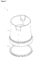
Figure 1 - is the perspective view of a body and a joining ring. -
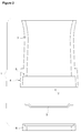
Figure 2 - is the exploded view of a coffeepot. -
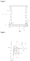
Figure 3 - is the schematic view of a coffeepot. -
Figure 4 - is the view of detail A inFigure 3 . - The elements illustrated in the figures are numbered as follows:
- 1.
- Coffeepot
- 2.
- Body
- 3.
- Base
- 4.
- Skirting
- 5.
- Bearing projection
- 6.
- Joining ring
- 7.
- Base retaining surface
- 8.
- Leak-proofing projection
- 9.
- Assembly hole
- The coffeepot (1) comprises a body (2) wherein boiling is carried out, made of plastic material and a base (3) joined with the body (2), providing to transfer heat from the heater by being emplaced on the heater.
- The base (3) is manufactured using a metal like aluminum, copper having high heat conductivity or of iron, steel or nickel that can be heated by induction currents.
- The coffeepot (1) comprises a base joining orifice (T), situated at the bottom of the body (2) upon which the base (3) is joined, a skirting (4) forming the circumference of the base joining orifice (T) at the bottom of the body (2), providing it to be seated on the floor, a bearing projection (5) extending towards the inner volume of the body (2) on which the base (3) bears on, emplaced to be joined with the body (2), and a joining ring (6) that
- is manufactured using plastic material,
- mounted on the base (3) emplaced on the bearing projection (5), providing to fit the base (3) tightly between the body (2) and itself,
- screwed on the inner wall of the skirting (4) such that it is peripherally in contact with the bearing projection (5) providing leak-proofing.
- The side surface of the joining ring (6) and the inner wall of the skirting (4) is of a screw joint type and the joining ring (6) is mounted on the base (3) by being screwed to the inner wall of the skirting (4) from its side surface and provides the base (3) to exert pressure on the bearing projection (5). The screw threads on the side surface of the joining ring (6) are shaped of a self-locking pitch and are not allowed to get loose after being assembled.
- The joining ring (6) comprises a base retaining surface (7) that fits tightly the side portion of the base (3) mounted on it in between the bearing projection (5) and itself and a leak-proofing projection (8) situated on the base retaining surface (7) providing leak-proofing by exerting pressure on the bearing projection (5) (Figure 5).
- The body (2) is manufactured using plastic material in an injection mould separately from the metal base (3). After the body (2) is manufactured, the base (3) is inserted into the body (2) through the base joining orifice (T), emplaced on the bearing projection (5) and the joining ring (6) is mounted on the base (3) completing the assembly of the coffeepot (1). The joining ring (6) exerts pressure on the base (3) from the base retaining surface (7) providing it to be attached to the body (2), furthermore by means of the leak-proofing projection (8) being seated on the bearing projection (5), the joining ring (6) manufactured using plastic material and the bearing projection (5) manufactured using plastic material, exert pressure on each other providing leak-proofing.
- In an embodiment of the present invention, the joining ring (6) comprises one or more assembly holes (9) that provides it to be screwed on the inner wall of the skirting (4) by turning with an apparatus inserted through and later pouring in an adhesive for fixing. In this embodiment, the assembly hole (9) extends to the screw threads on the side surface of the joining ring (6) and/or the leak-proofing projection (8) from the bottom surface of the joining ring (6), providing the adhesive poured in to reach the screwed inner wall of the skirting (4) and/or between the leak-proofing projection (8) and the bearing projection (5) (Figure 5).
- In this embodiment, after the base (3) is assembled to the body (2), the joining ring (6) is brought over the base (3) and screwed on the inner wall of the skirting (4) with the apparatus attached to the assembly holes (9), after the apparatus is taken out, adhesive is dribbled on the assembly holes (9) and the coffeepot (1) is held with its base (3) upside until the adhesive dries. Consequently a leak-proof and a durable base (3)- body (2) joint is achieved.
- By way of the plastic body (2) and the metal base (3) joint, a low cost coffeepot (1) with an easy manufacturing method is provided that is resistant to corrosion and bending. Since the body (2) that gets narrower from the bottom upwards is not manufactured in one piece with the base (3), it can easily be taken out of the mould, the base (3) is joined with the body (2) in a leak-proof way by means of the joining ring (6) and a durable base (3)-body (2) joint is provided by means of the assembly holes (9).
- The coffeepot (1) is used in coffee machines, particularly in coffee machines suitable for making Turkish coffee.
Claims (7)
- A coffeepot (1) comprising a body (2) made of plastic material and a base (3) joined with the body (2) manufactured using metal, and characterized by a skirting (4) forming the circumference of the base joining orifice (T) situated at the bottom of the body (2), providing it to be seated on the floor, a bearing projection (5) extending towards the inner volume of the body (2) on which the base (3) bears on that is emplaced to be joined with the body (2), and a joining ring (6) that is manufactured using plastic material, mounted on the base (3) emplaced on the bearing projection (5), providing to fit the base (3) tightly between the body (2) and itself, screwed on the inner wall of the skirting (4) such that it is in contact with the bearing projection (5) peripherally, providing leak-proofing.
- A coffeepot (1) as in Claim 1, characterized by a joining ring (6) with its side surface shaped as screw type joint and a skirting (4) with its inner wall shaped as screw type joint.
- A coffeepot (1) as in Claim 1 and 2, characterized by a joining ring (6) comprising a base retaining surface (7) that fits tightly the side portion of the base (3) seated on it between the bearing projection (5) and itself.
- A coffeepot (1) as in Claim 3, characterized by joining ring (6) comprising a leak-proofing projection (8) situated on the base retaining surface (7) providing leak-proofing by exerting pressure on the bearing projection (5).
- A coffeepot (1) as in any one of the above claims, characterized by joining ring (6) comprising one or more assembly holes (9) that provides it to be screwed on the inner wall of the skirting (4) by turning with an apparatus inserted through and later pouring in an adhesive for fixing in place.
- A coffeepot (1) as in Claim 5, characterized by a joining ring (6) comprising an assembly hole (9) that extends from the bottom surface of the joining ring (6) to the screw threads on the side surface of the joining ring (6) and/or the leak-proofing projection (8) providing the adhesive poured in to reach the screwed inner wall of the skirting (4) and/or between the leak-proofing projection (8) and the bearing projection (5).
- A coffeepot (1) as in any one of the above claims that is utilized in coffee machines suitable for making Turkish coffee.
Applications Claiming Priority (2)
| Application Number | Priority Date | Filing Date | Title |
|---|---|---|---|
| TR200600066 | 2006-01-05 | ||
| PCT/EP2006/069743 WO2007077105A1 (en) | 2006-01-05 | 2006-12-15 | A coffeepot |
Publications (2)
| Publication Number | Publication Date |
|---|---|
| EP1968417A1 EP1968417A1 (en) | 2008-09-17 |
| EP1968417B1 true EP1968417B1 (en) | 2016-02-24 |
Family
ID=37945851
Family Applications (1)
| Application Number | Title | Priority Date | Filing Date |
|---|---|---|---|
| EP06830639.8A Active EP1968417B1 (en) | 2006-01-05 | 2006-12-15 | A coffeepot |
Country Status (3)
| Country | Link |
|---|---|
| EP (1) | EP1968417B1 (en) |
| ES (1) | ES2571784T3 (en) |
| WO (1) | WO2007077105A1 (en) |
Family Cites Families (5)
| Publication number | Priority date | Publication date | Assignee | Title |
|---|---|---|---|---|
| GB334422A (en) * | 1929-10-15 | 1930-09-01 | Malcolm Cutts | Improvements in or relating to teapots, hot water jugs and like vessels for holding hot liquids |
| FR2748645B1 (en) * | 1996-05-14 | 1998-07-24 | Seb Sa | ELECTRIC KETTLE WITH METAL PLATE OF HEATER |
| EP0895772A1 (en) * | 1997-08-07 | 1999-02-10 | Seb S.A. | Heating device for a feeding bottle with a metallic bottom |
| EP1002488B1 (en) * | 1998-11-17 | 2001-09-12 | Bernd Schreitmüller | Electrical boiler |
| DE20213139U1 (en) * | 2002-08-27 | 2004-01-15 | 3Rd Angle (U.K.) Ltd., Highley | Electric kettle |
-
2006
- 2006-12-15 WO PCT/EP2006/069743 patent/WO2007077105A1/en active Application Filing
- 2006-12-15 ES ES06830639T patent/ES2571784T3/en active Active
- 2006-12-15 EP EP06830639.8A patent/EP1968417B1/en active Active
Also Published As
| Publication number | Publication date |
|---|---|
| ES2571784T3 (en) | 2016-05-26 |
| EP1968417A1 (en) | 2008-09-17 |
| WO2007077105A1 (en) | 2007-07-12 |
Similar Documents
| Publication | Publication Date | Title |
|---|---|---|
| JP6560221B2 (en) | Bowl of cooking container including fitting with electric device | |
| CN203272784U (en) | Elastic sealing device and middle flange | |
| KR100889722B1 (en) | Cooker for a induction range | |
| KR101147783B1 (en) | Cooking pot having Duplex based | |
| ITMI20002372A1 (en) | STAINLESS STEEL COOKING CONTAINER WITH HEATED COMPOSABLE CAPSULAR BOTTOM FOR MAGNETIC INDUCTION | |
| JP2010099196A (en) | Cooking utensil for induction range | |
| KR100834027B1 (en) | Cooking vessel for induction range | |
| EP1496778B1 (en) | Cooking utensil the covering of which comprises an ornamental piece and corresponding production method | |
| EP1968417B1 (en) | A coffeepot | |
| KR101110498B1 (en) | Heatable Double Vessel and Manufacturing Method thereof | |
| KR100954074B1 (en) | A manufacture method of aluminum cookware and aluminum cookware | |
| KR100659733B1 (en) | A manufacturing method of kitchen utensils for induction range | |
| CN204427742U (en) | The interior pot of cooking apparatus | |
| CN202653904U (en) | Liquid heating container, assembly and element plate | |
| CN202619375U (en) | Heating element plate, liquid heating container and elastic sealing element | |
| CN104799675B (en) | Cooker made from composite material and manufacturing method thereof | |
| CN204427743U (en) | The interior pot of cooking apparatus | |
| KR101064337B1 (en) | Heatable Double Vessel for Insulation and Manufacturing Method thereof | |
| KR102097014B1 (en) | Cook-ware having plate of prevent a heat deformation, and manufacture method of the induction frying-pan | |
| CN207492545U (en) | Cookware and cooking equipment | |
| CN203723993U (en) | Connecting assembly and cooking utensil with same | |
| JP2009254505A (en) | Electric rice cooker | |
| KR20140048510A (en) | Cooking pot for induction range and manufacture method thereof | |
| CN203074303U (en) | Electric heating kettle | |
| CN212489534U (en) | Pot and cooking utensil |
Legal Events
| Date | Code | Title | Description |
|---|---|---|---|
| PUAI | Public reference made under article 153(3) epc to a published international application that has entered the european phase |
Free format text: ORIGINAL CODE: 0009012 |
|
| 17P | Request for examination filed |
Effective date: 20080703 |
|
| AK | Designated contracting states |
Kind code of ref document: A1 Designated state(s): AT BE BG CH CY CZ DE DK EE ES FI FR GB GR HU IE IS IT LI LT LU LV MC NL PL PT RO SE SI SK TR |
|
| 17Q | First examination report despatched |
Effective date: 20090226 |
|
| DAX | Request for extension of the european patent (deleted) | ||
| GRAP | Despatch of communication of intention to grant a patent |
Free format text: ORIGINAL CODE: EPIDOSNIGR1 |
|
| INTG | Intention to grant announced |
Effective date: 20151022 |
|
| GRAS | Grant fee paid |
Free format text: ORIGINAL CODE: EPIDOSNIGR3 |
|
| GRAA | (expected) grant |
Free format text: ORIGINAL CODE: 0009210 |
|
| AK | Designated contracting states |
Kind code of ref document: B1 Designated state(s): AT BE BG CH CY CZ DE DK EE ES FI FR GB GR HU IE IS IT LI LT LU LV MC NL PL PT RO SE SI SK TR |
|
| REG | Reference to a national code |
Ref country code: GB Ref legal event code: FG4D |
|
| REG | Reference to a national code |
Ref country code: CH Ref legal event code: EP |
|
| REG | Reference to a national code |
Ref country code: AT Ref legal event code: REF Ref document number: 776204 Country of ref document: AT Kind code of ref document: T Effective date: 20160315 |
|
| REG | Reference to a national code |
Ref country code: IE Ref legal event code: FG4D |
|
| REG | Reference to a national code |
Ref country code: DE Ref legal event code: R096 Ref document number: 602006048045 Country of ref document: DE |
|
| REG | Reference to a national code |
Ref country code: ES Ref legal event code: FG2A Ref document number: 2571784 Country of ref document: ES Kind code of ref document: T3 Effective date: 20160526 |
|
| REG | Reference to a national code |
Ref country code: LT Ref legal event code: MG4D |
|
| REG | Reference to a national code |
Ref country code: NL Ref legal event code: MP Effective date: 20160224 |
|
| REG | Reference to a national code |
Ref country code: AT Ref legal event code: MK05 Ref document number: 776204 Country of ref document: AT Kind code of ref document: T Effective date: 20160224 |
|
| PG25 | Lapsed in a contracting state [announced via postgrant information from national office to epo] |
Ref country code: FI Free format text: LAPSE BECAUSE OF FAILURE TO SUBMIT A TRANSLATION OF THE DESCRIPTION OR TO PAY THE FEE WITHIN THE PRESCRIBED TIME-LIMIT Effective date: 20160224 |
|
| PG25 | Lapsed in a contracting state [announced via postgrant information from national office to epo] |
Ref country code: NL Free format text: LAPSE BECAUSE OF FAILURE TO SUBMIT A TRANSLATION OF THE DESCRIPTION OR TO PAY THE FEE WITHIN THE PRESCRIBED TIME-LIMIT Effective date: 20160224 Ref country code: PT Free format text: LAPSE BECAUSE OF FAILURE TO SUBMIT A TRANSLATION OF THE DESCRIPTION OR TO PAY THE FEE WITHIN THE PRESCRIBED TIME-LIMIT Effective date: 20160624 Ref country code: AT Free format text: LAPSE BECAUSE OF FAILURE TO SUBMIT A TRANSLATION OF THE DESCRIPTION OR TO PAY THE FEE WITHIN THE PRESCRIBED TIME-LIMIT Effective date: 20160224 Ref country code: SE Free format text: LAPSE BECAUSE OF FAILURE TO SUBMIT A TRANSLATION OF THE DESCRIPTION OR TO PAY THE FEE WITHIN THE PRESCRIBED TIME-LIMIT Effective date: 20160224 Ref country code: LV Free format text: LAPSE BECAUSE OF FAILURE TO SUBMIT A TRANSLATION OF THE DESCRIPTION OR TO PAY THE FEE WITHIN THE PRESCRIBED TIME-LIMIT Effective date: 20160224 Ref country code: LT Free format text: LAPSE BECAUSE OF FAILURE TO SUBMIT A TRANSLATION OF THE DESCRIPTION OR TO PAY THE FEE WITHIN THE PRESCRIBED TIME-LIMIT Effective date: 20160224 Ref country code: PL Free format text: LAPSE BECAUSE OF FAILURE TO SUBMIT A TRANSLATION OF THE DESCRIPTION OR TO PAY THE FEE WITHIN THE PRESCRIBED TIME-LIMIT Effective date: 20160224 |
|
| REG | Reference to a national code |
Ref country code: GR Ref legal event code: EP Ref document number: 20160400878 Country of ref document: GR Effective date: 20160628 |
|
| PG25 | Lapsed in a contracting state [announced via postgrant information from national office to epo] |
Ref country code: EE Free format text: LAPSE BECAUSE OF FAILURE TO SUBMIT A TRANSLATION OF THE DESCRIPTION OR TO PAY THE FEE WITHIN THE PRESCRIBED TIME-LIMIT Effective date: 20160224 Ref country code: DK Free format text: LAPSE BECAUSE OF FAILURE TO SUBMIT A TRANSLATION OF THE DESCRIPTION OR TO PAY THE FEE WITHIN THE PRESCRIBED TIME-LIMIT Effective date: 20160224 |
|
| REG | Reference to a national code |
Ref country code: DE Ref legal event code: R097 Ref document number: 602006048045 Country of ref document: DE |
|
| PG25 | Lapsed in a contracting state [announced via postgrant information from national office to epo] |
Ref country code: CZ Free format text: LAPSE BECAUSE OF FAILURE TO SUBMIT A TRANSLATION OF THE DESCRIPTION OR TO PAY THE FEE WITHIN THE PRESCRIBED TIME-LIMIT Effective date: 20160224 Ref country code: RO Free format text: LAPSE BECAUSE OF FAILURE TO SUBMIT A TRANSLATION OF THE DESCRIPTION OR TO PAY THE FEE WITHIN THE PRESCRIBED TIME-LIMIT Effective date: 20160224 Ref country code: SK Free format text: LAPSE BECAUSE OF FAILURE TO SUBMIT A TRANSLATION OF THE DESCRIPTION OR TO PAY THE FEE WITHIN THE PRESCRIBED TIME-LIMIT Effective date: 20160224 |
|
| PG25 | Lapsed in a contracting state [announced via postgrant information from national office to epo] |
Ref country code: BE Free format text: LAPSE BECAUSE OF FAILURE TO SUBMIT A TRANSLATION OF THE DESCRIPTION OR TO PAY THE FEE WITHIN THE PRESCRIBED TIME-LIMIT Effective date: 20160224 |
|
| PLBE | No opposition filed within time limit |
Free format text: ORIGINAL CODE: 0009261 |
|
| STAA | Information on the status of an ep patent application or granted ep patent |
Free format text: STATUS: NO OPPOSITION FILED WITHIN TIME LIMIT |
|
| 26N | No opposition filed |
Effective date: 20161125 |
|
| PG25 | Lapsed in a contracting state [announced via postgrant information from national office to epo] |
Ref country code: SI Free format text: LAPSE BECAUSE OF FAILURE TO SUBMIT A TRANSLATION OF THE DESCRIPTION OR TO PAY THE FEE WITHIN THE PRESCRIBED TIME-LIMIT Effective date: 20160224 Ref country code: BG Free format text: LAPSE BECAUSE OF FAILURE TO SUBMIT A TRANSLATION OF THE DESCRIPTION OR TO PAY THE FEE WITHIN THE PRESCRIBED TIME-LIMIT Effective date: 20160524 |
|
| REG | Reference to a national code |
Ref country code: CH Ref legal event code: PL |
|
| PG25 | Lapsed in a contracting state [announced via postgrant information from national office to epo] |
Ref country code: MC Free format text: LAPSE BECAUSE OF FAILURE TO SUBMIT A TRANSLATION OF THE DESCRIPTION OR TO PAY THE FEE WITHIN THE PRESCRIBED TIME-LIMIT Effective date: 20160224 |
|
| REG | Reference to a national code |
Ref country code: FR Ref legal event code: ST Effective date: 20170831 |
|
| REG | Reference to a national code |
Ref country code: IE Ref legal event code: MM4A |
|
| PG25 | Lapsed in a contracting state [announced via postgrant information from national office to epo] |
Ref country code: LI Free format text: LAPSE BECAUSE OF NON-PAYMENT OF DUE FEES Effective date: 20161231 Ref country code: FR Free format text: LAPSE BECAUSE OF NON-PAYMENT OF DUE FEES Effective date: 20170102 Ref country code: LU Free format text: LAPSE BECAUSE OF NON-PAYMENT OF DUE FEES Effective date: 20161215 Ref country code: CH Free format text: LAPSE BECAUSE OF NON-PAYMENT OF DUE FEES Effective date: 20161231 |
|
| PG25 | Lapsed in a contracting state [announced via postgrant information from national office to epo] |
Ref country code: IE Free format text: LAPSE BECAUSE OF NON-PAYMENT OF DUE FEES Effective date: 20161215 |
|
| PG25 | Lapsed in a contracting state [announced via postgrant information from national office to epo] |
Ref country code: CY Free format text: LAPSE BECAUSE OF FAILURE TO SUBMIT A TRANSLATION OF THE DESCRIPTION OR TO PAY THE FEE WITHIN THE PRESCRIBED TIME-LIMIT Effective date: 20160224 Ref country code: HU Free format text: LAPSE BECAUSE OF FAILURE TO SUBMIT A TRANSLATION OF THE DESCRIPTION OR TO PAY THE FEE WITHIN THE PRESCRIBED TIME-LIMIT; INVALID AB INITIO Effective date: 20061215 |
|
| PG25 | Lapsed in a contracting state [announced via postgrant information from national office to epo] |
Ref country code: IS Free format text: LAPSE BECAUSE OF FAILURE TO SUBMIT A TRANSLATION OF THE DESCRIPTION OR TO PAY THE FEE WITHIN THE PRESCRIBED TIME-LIMIT Effective date: 20160224 |
|
| PGFP | Annual fee paid to national office [announced via postgrant information from national office to epo] |
Ref country code: ES Payment date: 20230224 Year of fee payment: 17 |
|
| P01 | Opt-out of the competence of the unified patent court (upc) registered |
Effective date: 20230523 |
|
| PGFP | Annual fee paid to national office [announced via postgrant information from national office to epo] |
Ref country code: GR Payment date: 20231221 Year of fee payment: 18 Ref country code: GB Payment date: 20231220 Year of fee payment: 18 |
|
| PGFP | Annual fee paid to national office [announced via postgrant information from national office to epo] |
Ref country code: TR Payment date: 20231124 Year of fee payment: 18 Ref country code: IT Payment date: 20231228 Year of fee payment: 18 Ref country code: DE Payment date: 20231214 Year of fee payment: 18 |
|
| PGFP | Annual fee paid to national office [announced via postgrant information from national office to epo] |
Ref country code: ES Payment date: 20240126 Year of fee payment: 18 |