EP1968218A1 - Multi-channel transmitter - Google Patents
Multi-channel transmitter Download PDFInfo
- Publication number
- EP1968218A1 EP1968218A1 EP07004752A EP07004752A EP1968218A1 EP 1968218 A1 EP1968218 A1 EP 1968218A1 EP 07004752 A EP07004752 A EP 07004752A EP 07004752 A EP07004752 A EP 07004752A EP 1968218 A1 EP1968218 A1 EP 1968218A1
- Authority
- EP
- European Patent Office
- Prior art keywords
- signal
- channels
- transmitter device
- intermediate frequency
- radio transmitter
- Prior art date
- Legal status (The legal status is an assumption and is not a legal conclusion. Google has not performed a legal analysis and makes no representation as to the accuracy of the status listed.)
- Granted
Links
- 230000005540 biological transmission Effects 0.000 claims abstract description 31
- 230000005236 sound signal Effects 0.000 claims abstract description 31
- 238000000034 method Methods 0.000 claims abstract description 8
- 230000007274 generation of a signal involved in cell-cell signaling Effects 0.000 claims description 10
- 230000008901 benefit Effects 0.000 description 6
- 238000005562 fading Methods 0.000 description 4
- 230000000694 effects Effects 0.000 description 3
- 230000006870 function Effects 0.000 description 3
- 230000003287 optical effect Effects 0.000 description 2
- XUIMIQQOPSSXEZ-UHFFFAOYSA-N Silicon Chemical compound [Si] XUIMIQQOPSSXEZ-UHFFFAOYSA-N 0.000 description 1
- 230000015556 catabolic process Effects 0.000 description 1
- 238000004891 communication Methods 0.000 description 1
- 230000000295 complement effect Effects 0.000 description 1
- 238000004590 computer program Methods 0.000 description 1
- 238000006731 degradation reaction Methods 0.000 description 1
- 230000001066 destructive effect Effects 0.000 description 1
- 238000005516 engineering process Methods 0.000 description 1
- 239000000945 filler Substances 0.000 description 1
- 230000004048 modification Effects 0.000 description 1
- 238000012986 modification Methods 0.000 description 1
- 230000001105 regulatory effect Effects 0.000 description 1
- 229910052710 silicon Inorganic materials 0.000 description 1
- 239000010703 silicon Substances 0.000 description 1
- 239000007787 solid Substances 0.000 description 1
Images


Classifications
-
- H—ELECTRICITY
- H04—ELECTRIC COMMUNICATION TECHNIQUE
- H04H—BROADCAST COMMUNICATION
- H04H60/00—Arrangements for broadcast applications with a direct linking to broadcast information or broadcast space-time; Broadcast-related systems
- H04H60/76—Arrangements characterised by transmission systems other than for broadcast, e.g. the Internet
- H04H60/78—Arrangements characterised by transmission systems other than for broadcast, e.g. the Internet characterised by source locations or destination locations
- H04H60/80—Arrangements characterised by transmission systems other than for broadcast, e.g. the Internet characterised by source locations or destination locations characterised by transmission among terminal devices
-
- H—ELECTRICITY
- H04—ELECTRIC COMMUNICATION TECHNIQUE
- H04H—BROADCAST COMMUNICATION
- H04H20/00—Arrangements for broadcast or for distribution combined with broadcast
- H04H20/20—Arrangements for broadcast or distribution of identical information via plural systems
- H04H20/22—Arrangements for broadcast of identical information via plural broadcast systems
-
- H—ELECTRICITY
- H04—ELECTRIC COMMUNICATION TECHNIQUE
- H04H—BROADCAST COMMUNICATION
- H04H20/00—Arrangements for broadcast or for distribution combined with broadcast
- H04H20/26—Arrangements for switching distribution systems
-
- H—ELECTRICITY
- H04—ELECTRIC COMMUNICATION TECHNIQUE
- H04H—BROADCAST COMMUNICATION
- H04H20/00—Arrangements for broadcast or for distribution combined with broadcast
- H04H20/53—Arrangements specially adapted for specific applications, e.g. for traffic information or for mobile receivers
- H04H20/61—Arrangements specially adapted for specific applications, e.g. for traffic information or for mobile receivers for local area broadcast, e.g. instore broadcast
- H04H20/62—Arrangements specially adapted for specific applications, e.g. for traffic information or for mobile receivers for local area broadcast, e.g. instore broadcast for transportation systems, e.g. in vehicles
-
- H—ELECTRICITY
- H04—ELECTRIC COMMUNICATION TECHNIQUE
- H04H—BROADCAST COMMUNICATION
- H04H2201/00—Aspects of broadcast communication
- H04H2201/10—Aspects of broadcast communication characterised by the type of broadcast system
- H04H2201/13—Aspects of broadcast communication characterised by the type of broadcast system radio data system/radio broadcast data system [RDS/RBDS]
Landscapes
- Engineering & Computer Science (AREA)
- Signal Processing (AREA)
- Transmitters (AREA)
Abstract

Description
- This invention relates to transmission apparatus for transmitting an audio signal from an audio device to a radio receiver and to a corresponding method of transmitting an audio signal. This invention also relates more generally to a transmitter device which transmits on multiple channels.
- Portable media players are an increasingly popular way for a user to carry around their collection of media content. The media content can include audio content such as music tracks and podcasts as well as video content. A user often wants to connect their media player to the audio system in a vehicle, so that they can listen to the audio content through the speakers of the vehicle's audio system. Some vehicles have dedicated connectors, such as jack sockets or a proprietary interface, but many vehicles lack this feature.
- One known way of connecting a media player to a vehicle's audio system is to use a low-powered Frequency Modulated (FM) transmitter. The transmitter receives an audio input from the media payer and modulates this onto one of the frequency channels of the VHF FM radio frequency band (87.5-108MHz) used for licensed radio broadcasts. In this way, the audio output of the media player can be received in the same manner as a conventional FM radio broadcast on the vehicle's FM radio receiver. Regulatory bodies in many countries now allow unlicensed use of these low-power transmitter devices. The transmitter device stores a single transmission frequency which can typically be selected by a user from one of the frequencies across the VHF FM band. In use, a user manually selects a free channel which is not used by a broadcast radio station and selects this as the frequency at which the low-power transmitter device will operate. The in-vehicle radio receiver is tuned to the same channel.
- One of the problems with using a device of this kind is that, as a user drives across a region, they may find that the channel they had selected for the low-power transmission is used by a high-powered licensed transmission of a radio station. This requires the user to manually retune both the transmitter device and the in-vehicle radio receiver to a new channel. This is inconvenient, and can be dangerous if a user attempts this operation whilst driving.
- The Radio Data System (RDS) is widely used by broadcasters operating in the VHF FM band. The latest version of the RDS standard is published by the International Electrotechnical Commission (IEC) as IEC 62106 (1999). RDS adds a sub-carrier to the FM multiplex at 57kHz which carries digital data. As FM transmissions have a limited range, a national radio station has to broadcast on different frequencies in neighbouring regions to avoid interference. One of the uses of the RDS data channel is to carry a list of Alternate Frequencies. This is a list of neighbouring VHF FM transmitting stations which broadcast the same radio station. When the radio station is received weakly on the current channel, the receiver can select one of the channels specified in the Alternate Frequency list and retune to that channel.
-
WO 2006/106379A1 describes a device for low-power transmission of audio data to an RDS-capable radio receiver. The device performs a scan of available radio frequencies and selects one of the available frequencies for transmission. Audio data is transmitted over that frequency in a conventional manner by frequency modulating the carrier frequency. Details of the other available frequencies that were found during the scan are sent to the receiver using the Alternate Frequency (AF) field of an RDS data channel forming part of the transmitted signal.WO 2006/106379 only transmits on a single frequency channel at any time. Under poor transmission conditions, there can be uncertainty as to when the device will select one of the alternate frequencies, and which one of the alternate frequencies it will choose. Also, under conditions of multi-path fading, a receiver can experience poor reception of the channel selected by the transmitter device at a time when the transmitter device considers the selected channel is acceptable. - An object of the present invention is to provide improved apparatus and an improved way of transmitting an audio signal to a radio receiver.
- By simultaneously transmitting on a set of different channels, the receiver can select one of the alternate channels at any time, and retune to this. One problem which can affect low-power, short range, transmissions is multi-path fading. Multi-path fading can seriously degrade the quality of signal at the receiver, but as this degradation is local to the receiver it may not be detected by the transmitter device. By simultaneously transmitting on a set of different channels, the receiver can select one of the alternate channels at any time, independently of the transmitter, and can therefore overcome the effects of multi-path fading. The set of RF signals can comprise two or more RF signals. The upper limit will be bounded by practical limitations such as cost to implement the transmitter and the amount of power that would be consumed by a large number of transmitted signals.
- The information identifying the other RF channels could be carried by another type of communication, e.g. Bluetooth. For example if the receiver is configured for Bluetooth, this signal could be sent over a Bluetooth link.
- Preferably, the identification of alternate channels is achieved by using the Alternate Frequency (AF) field of an RDS data channel carried by each of the transmitted signals. The radio receiver needs to be RDS-capable to receive, and use, the AF data. However, even non-RDS receivers can benefit from the invention as in the event of interference occurring on the current RF channel, there is only a need to retune the receiver to another one of the RF channels on which the transmitter device transmits. The tuning can be performed manually or by using the conventional band scanning feature of a receiver.
- The set of RF channels on which the transmitter device transmits can be permanently fixed, or at least one of the set can be manually selectable by a user, or automatically selectable by the transmitter device. One way of automatically selecting the channel is for the transmitter device to incorporate a receiver which is arranged to scan of a band of channels and to select an available channel based on the results of the scan.
- Some adjustment of at least one of the RF channels in case all of the N transmitted RF signals interfere with existing broadcasting stations can be included within the scope of the present invention. The present invention includes the combination of a "silent frequency scan" and the multi-channel transmitter. An alternative or complement to the silent scan can be to store a preferred frequency list based on user experience by location (e.g. at HOME, in the office, on location, on holiday etc).
- The RF channels on which the transmitter device transmits can be VHF FM band channels although the invention can be applied to any other existing, or future, transmission schemes.
- The transmitter device can be a unit which is manufactured and sold separately from the audio device. In this case, the transmitter device can receive the audio signal via an interface between the devices. The audio input can be in the form of an analog signal (at baseband or modulated in some way) or in the form of a digital data signal representing audio data. The interface can be electrical or optical, e.g. jack socket, RCA connector, Sony/Philips Digital Interface Format (S/PDIF) or TOSLINK digital connector, IEEE 1394, Universal Serial Bus (USB) or a proprietary interface. The interface can be a cable which is terminated with appropriate connectors or the transmitter device can be implemented as a housing which has a connector projecting from it, which is intended to plug directly into an audio output socket of the audio device. Alternatively, the transmitter device can be integrated within the audio device and can receive the audio input signal via an internal analog or digital interface.
- The audio device can be a media player or any other device which emits an audio signal, such as a mobile telephone, voice recorder, Personal Digital Assistant (PDA) or personal computer. The form of the media player is unimportant and in can be, for example, a player which stores media content on a hard disk or solid state memory, a compact disc player or a tape player. The radio receiver is preferably a conventional radio receiver, such as a VHF FM receiver, which requires no modification.
- A significant part of the transmitter device can be implemented in the digital domain. This can be achieved by software executed by a general-purpose or dedicated processor, by digital hardware or a combination of these. In addition, the control functions of the transmitter device can be implemented by software executed by a processor or by control logic. Accordingly, another aspect of the invention provides software for causing a processor of a radio transmitter device to implement the method described above. The software may be stored on an electronic memory device, hard disk, optical disk or other machine-readable storage medium. The software may be delivered as a computer program product on a machine-readable carrier or it may be downloaded to the transmitter device via a network connection.
- Another aspect of the present invention seeks to simplify the apparatus required to transmit on multiple channels.
- Accordingly, another aspect of the present invention provides a radio transmitter device comprising:
- an input for receiving an input signal;
- a transmitter arranged to simultaneously transmit an RF signal which is modulated with the input signal on each of a set of at least two different RF channels, wherein the transmitter comprises:
- a set of intermediate frequency modulation stages arranged in parallel with one another, each intermediate frequency modulation stage arranged to modulate a selected intermediate frequency with the input signal, wherein the set of intermediate frequencies are offset from one another in the same relationship as the set of RF channels; and,
- an RF stage arranged to translate the modulated intermediate frequency signals to an RF transmission frequency band.
- An advantage of the transmitter device is that the RF stage is simplified, as each of the signals in the set of intermediate frequencies can be translated by the same offset frequency to the RF transmission frequency band. Preferably, a single RF stage translates all of the modulated intermediate frequency signals to an RF transmission frequency band. Embodiments of the present invention can have either a common RF stage or individual RF stages which work in the same way. The present invention also includes embodiments that do not have different IF frequencies, and which use different local oscillators (LO) running at different frequencies
- The main advantage of embodiments shown in
Figs. 9 and11 is the low extra cost for implementing the multi-channel transmitter. Other implementations are included in the scope of the present invention, for example, using different local oscillator frequency signals or by putting different IF mixers between the DAC and the RF mixer - In situations where the input signal requires formatting before modulation (e.g. converting a stereo audio signal into an FM Multiplex (MPX) format), a single signal generation stage can perform the formatting before feeding the formatted signal to each of the intermediate frequency modulation stages. This further reduces the amount of apparatus to implement the transmitter device.
- Embodiments of the invention will be described, by way of example only, with reference to the accompanying drawings in which:
-
Figure 1 shows a system for transmitting audio signal to an FM radio receiver which uses a transmitter device according to the present invention; -
Figure 2 shows a plot, in the frequency domain, of the signals output by the transmitter device; -
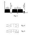
Figure 3 shows a conventional FM multiplex; -
Figures 4 and 5 show formats for sending RDS Alternate Frequency data; -
Figures 6 and 7 show embodiments of the transmitter device using parallel transmission stages; -
Figure 8 shows a plot, in the frequency domain, to illustrate operation of a transmitter device in accordance with the present invention which generates signals at multiple intermediate frequencies; -
Figure 9 shows a first embodiment of a transmitter device which generates signals at multiple intermediate frequencies; -
Figure 10 shows a second embodiment of a transmitter device which generates signals at multiple intermediate frequencies; -
Figure 11 shows a third embodiment of a transmitter device which generates signals at multiple intermediate frequencies; and, -
Figure 12 shows an enhancement to the transmitter device in which a receiver is provided for detecting available channels. - The present invention will be described with respect to particular embodiments and with reference to certain drawings but the invention is not limited thereto but only by the claims. The drawings described are only schematic and are non-limiting. In the drawings, the size of some of the elements may be exaggerated and not drawn on scale for illustrative purposes. Where the term "comprising" is used in the present description and claims, it does not exclude other elements or steps. Furthermore, the terms first, second, third and the like in the description and in the claims, are used for distinguishing between similar elements and not necessarily for describing a sequential or chronological order. It is to be understood that the terms so used are interchangeable under appropriate circumstances and that the embodiments of the invention described herein are capable of operation in other sequences than described or illustrated herein.
-
Figure 1 shows a system in accordance with an embodiment of the present invention. An audio device such as amedia player 10 or mobile telephone (or for example a laptop computer, a smartphone, home (multi-media) entertainment equipment, etc.) is connected to atransmitter device 20 and feeds anaudio signal 15 to thetransmitter device 20. The connection between themedia player 10 andtransmitter device 20 can be achieved by any suitable connection technology, such as by an audio connecting lead which is terminated in a manner which matches themedia player 10 andtransmitter device 20. Thetransmitter device 20 can be implemented as a device which is separate from the media player. Thetransmitter device 20 can physically mount on, or alongside, themedia player 10. Alternatively, thetransmitter device 20 can be incorporated within themedia player 10 itself or vice versa.Transmitter device 20 modulates the audio signal received from themedia player 10 onto a set of different frequency channels and transmits this set of signals from anantenna 29. These frequency channels, for example, can be distributed across a VHF FM band. Each of the signals in the set carries a copy of the same audio signal. The signals are received by a radio receiver, e.g. a conventional VHF-bandFM radio receiver 40 receives the signals transmitted by thetransmitter device 20. Thereceiver 40 can form part of an in-vehicle audio system. In a conventional manner, the in-vehicle audio system comprises a selector 50 for selecting one of the input sources, an audio amplifier 51 andaudio speakers 52. In the case of an in-vehicle system,antenna 42 will typically be mounted on the exterior surface of the vehicle, or in the rear screen. The transmission path between thetransmitter device 20 andreceiver 40 can be adirect path 31 but more usually it will includemultiple components Component 32 is shown reflected off a surface of the vehicle. The different lengths of the paths travelled bycomponents components antenna 42. These will usually have a much greater power than the signals from thetransmitter device 20. From time-to-time, signals 35 will occupy the same frequency as one of the signals transmitted by thetransmitter device 20 and will interfere with that frequency. -
Figure 2 shows the output of atransmitter device 20. TheVHF FM band 100 typically occupies a frequency range of 76MHz-108MHz, e.g. 87.5 - 108 MHz, or any other limits of this band depending upon the regulations of the country or countries involved. The transmitter device transmits a set ofsignals media player 10, modulated in a conventional FM multiplex format. Eachsignal -
Figure 3 shows the conventional format of an FM multiplex. For compatibility withconventional FM receivers 40, thetransmitter device 20 transmits the audio signal from themedia player 10 in this conventional format. The FM multiplex comprises a sum (L+R) of the left and right channels of a stereo audio signal and a difference (L-R) of the left and right channels of the stereo audio signal. The sum signal is transmitted as baseband audio in the range 30Hz to 15kHz. The difference (L-R) signal is amplitude modulated onto a 38kHz suppressed carrier to produce a double-sideband suppressed carrier (DSBSC) signal in the range 23kHz - 53kHz. A 19kHz pilot tone is also transmitted and used by the receiver to regenerate the 38kHz subcarrier. A further subcarrier at 57kHz carries the RDS data. The entire FM multiplex is then frequency modulated onto a carrier and translated to the required VHF channel frequency. - One feature of the RDS data channel is Alternate Frequency (AF) data which identifies other transmitting stations broadcasting the same content. In the present invention, instead of using AF data to identify the frequency of other transmitting stations broadcasting the same content, the AF data identifies each of the other frequencies that the
transmitter device 20 is using. For example, the AF data insignal 101 will identify the frequencies ofsignals signal 102 will identify the frequencies ofsignals block 3 of each 0A group. The first byte in the transmitted list indicates the number of Alternate Frequencies in the list.Figure 4 shows the format of a transmission carrying three AFs. The first AF code represents the number of Alternate Frequencies (3) and the following three AF codes identify the frequencies. The AF codes are carried in pairs within two type 0A groups.Figure 5 shows the format of a transmission carrying two AFs. The first AF code represents the number of Alternate Frequencies (2) and the following two AF codes identify the frequencies. The final, unused, AF code space is occupied by a code having a filler value which signifies this AF field is unused. -
Radio receiver 40 operates in a conventional manner.Receiver 40 is typically a superheterodyne receiver which receives a signal from theantenna 42, translates it to a fixed intermediate frequency (IF) by mixing the received signal with a locally generated signal, and the filters and demodulates the IF signal to extract the required audio signal and RDS data.Receiver 40 monitors the quality of the received signal. When the quality of the received signal falls below a predetermined threshold quality, the receiver inspects the Alternate Frequency list in the RDS data, tunes to one of the alternate frequency channels, and monitors quality of the received signal on the new channel. The receiver can retune multiple times until an alternate frequency channel offers the required quality. - The
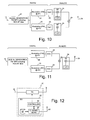
transmitter device 20 will now be described in more detail. There are a range of ways in which the set of simultaneous transmissions at different frequencies can be achieved.Figure 6 shows a first embodiment of thetransmitter device 20 in which two transmitters TX_A, TX_B are arranged in parallel. Theaudio signal 15 is applied to each of the transmitters. Each transmitter has an antenna.Figure 7 shows a second embodiment of thetransmitter device 20, in which two transmitters TX_A, TX_B are arranged in parallel. Theaudio signal 15 is applied to each of the transmitters. The RF output of each transmitter TX_A, TX_B is summed and applied to a single shared antenna. -
Figures 8-12 show embodiments of thetransmitter device 20 which use a single transmitter. These embodiments share the concept of generating a different intermediate frequency (IF) for each of the transmitted channels, combining the signals at the different IF frequencies, and then translating the set of signals at the different IF frequencies to the RF band by use of a common local oscillator frequency. The embodiments differ in the number of stages of the apparatus which are implemented in the analog domain, using analog circuitry, and in the digital domain, using digital processing. -
Figure 8 shows a plot in the frequency domain to illustrate the use of different IF frequencies. In this example there is a set of three transmitted signals but the invention can be applied more generally to a set of N signals. The frequency, at RF, (f_RF) of each signal is the sum of an IF frequency (f_IF) and a local oscillator frequency (f_LO) which is used to shift the signal from IF to RF:


-
Figure 9 shows an embodiment of thetransmitter device 20 in which generation of the FM multiplex signal, modulation at multiple intermediate frequencies and summation is all performed in the digital domain. Asignal generation stage 21 receives theaudio signal 15 from themedia player 10. An FM multiplex MPX is generated, in the digital domain. This FM MPX has the format shown inFigure 3 and includes Alternate Frequency (AF) RDS data identifying the other RF channels. - If
stage 21 is shared, the AF data added atstage 21 can be exactly the same for each of the signals, e.g. signal 101 can carry an identification of itself and of 102, 103 or thesignal 101 could only list 102, 103 and not itself. - The digital FM MPX signal is applied to a pair of modulating
stages first stage 22 frequency modulates the FM MPX signal to IF and thesecond stage 23 frequency modulates the FM MPX signal to IF2. - The FM modulator may be implemented in any of a number of different topologies, each of which is an embodiment of the present invention. For example, a phase accumulator with lookup table may be provided, or using DSP or using software. The IF frequency is not necessarily a limiting factor for multi-channel transmission. Some practical limitations may be implied by the (analog) signal processing chain and the specifications of the building blocks (filter bandwidth, linearity specifications, current consumption, etc). Also the bandwidth of the antenna can be a limit of the IF spacing of the topology. One prefered range of the IF is in the range from a few 100kHz, e.g. 2 kHz, to a few MHz, e.g. 8 MHz (also negative if possible).
- The resulting pair of signals at their respective intermediate frequencies IF1, IF2 are then digitally summed 24. This digital signal is converted to the analog domain by digital-to-
analog converter 25. The analog signal is translated to RF (specifically, the VHF FM band) by mixing with a local oscillator. The resulting RF signal is applied toantenna 29. It can be seen that this embodiment has an advantage over the embodiment shown inFigures 6 and 7 in that that only a singlesignal generation stage 21 is required. Also, this embodiment has an advantage in that only a single analog RF stage is required, which reduces the size and cost of the apparatus (e.g. reduced silicon area). Therefore, the overall increase in apparatus to implement transmission on multiple channels is not significant, and is limited to additional digital processing which can be achieved relatively cheaply. - The analog RF stage can optionally be adapted to cope with there being multiple IF signals. From a topology point of view the blocks can be shared. For the digital processing before the FM modulation there is no extra cost. The requirements of the analog blocks can change : for example, the linearity of the multi-tone signal instead of a single tone or to cover the changed dynamic range of each signal.
-
Figure 10 shows an embodiment of thetransmitter device 20 in which generation of the FM multiplex signal and modulation at multiple intermediate frequencies is performed in the digital domain. As previously described, asignal generation stage 21 receives theaudio signal 15 from themedia player 10. An FM multiplex MPX is generated, in the digital domain. The digital FM MPX signal is applied to a pair of modulatingstages analog converter 25. Each analog signal is then translated to RF by a respectiveanalog RF stage 26. As both of the RF stages 26 have the same function, a single local oscillator (LO) can be shared by both of the analog stages 26. The resulting pair of RF signals, each at a different VHF frequency, is combined 24 and applied toantenna 29. It can be seen that this embodiment also has an advantage over the embodiment shown inFigures 6 and 7 in that that only a singlesignal generation stage 21 is required. -
Figure 11 shows a further embodiment of thetransmitter device 20 in which generation of the FM multiplex signal and modulation at multiple intermediate frequencies is performed in the digital domain. As previously described, asignal generation stage 21 receives theaudio signal 15 from themedia player 10. An FM multiplex MPX is generated, in the digital domain. The digital FM MPX signal is applied to a pair of modulatingstages analog converter 25. The pair of modulated signals are then combined 24. The combined analog signal is then translated to RF by ananalog RF stage 26 and the RF signal is applied toantenna 29. - Further variants of the transmitter device (not shown) can be derived. For example, IF mixing in the analog domain, combination after the DAC, before or after an the RF mixer, before or after the RF amplifier, etc
- The present invention includes within its scope that an entirely digital transmitter is provided which directly creates the RF-band modulated signal, i.e. which removes the need for an analog RF mixing stage. For a digital transmitter two configurations could be considered: digital modulation of the RF oscillator or using a high frequency D/A converter. For the digital controlled oscillator, generation of a multi channel signal is less preferred. A high speed DAC is also included within the scope of the present invention.
- The set of RF channels on which the
transmitter device 20 transmits can be fixed or, more preferably, is variable to cope with the local environment. The value of at least one of the RF channels can be manually adjustable by a user. The number of the transmitted signals which is variable in transmission frequency can be only one of the signals, a sub-set of the full set of signals, or all of the set of signals.Figure 12 shows a further embodiment of thetransmitter device 20. The transmitter TX can be implemented in any of the ways shown inFigures 6 to 11 . Areceiver 60 receives signals from the local environment via anantenna 63. Achannel scan function 62 automatically scans the VHF FM band and detects activity on each of the channels. The results can be stored in amemory 64.Controller 61 selects the channels which, based on the scan results, appear to have the least activity and notifies transmitter TX of these channels. Transmitter TX selects these channels for the transmissions. In the embodiments ofFigures 8 to 11 , the channels can be selected by varying the IF frequency instages - The above description describes how the Alternate Frequency (AF) field of an RDS data channel can be used to send details of other frequencies used by the transmitter device. Additionally, other fields of the RDS data channel can also be used. The Program Service (PS) field, usually carries data which can display an eight-character identification of the radio station at a radio receiver. This field can be used to carry an identification of the media player so that a user knows they have tuned the
receiver 40 to one of frequencies used by thetransmitter device 20. The Radio Text (RT) field allows a radio station to transmit a 64-character string of text. This field can be used to carry an identification of the media item currently being played, such as song title, album name, podcast title etc. - The invention is not limited to the embodiments described herein, which may be modified or varied without departing from the scope of the invention.
Claims (28)
- A radio transmitter device for radio transmission of an audio signal from an audio device to a radio receiver, the radio transmitter device comprising:an audio input for receiving an audio signal from the audio device;a transmitter arranged to simultaneously transmit an RF signal which is modulated with the audio signal on each of a set of at least two different RF channels and the transmitter is further arranged to include, within each of the transmitted RF signals, at least information identifying the other RF channels in the set of RF channels.
- A radio transmitter device according to claim 1 wherein the transmitter is arranged to send the information about the other RF channels in the Alternate Frequency field of an RDS subcarrier.
- A radio transmitter device according to claim 1 or 2 wherein the value of at least one of the RF channels in the set is selectable from a range of possible RF channels.
- A radio transmitter device according to claim 3 further comprising a receiver arranged to scan for available RF channels and the transmitter is arranged to select the value of the at least one selectable RF channel based on results of the scan.
- A radio transmitter device according to any one of the preceding claims wherein the transmitter comprises a set of transmitter units arranged in parallel with one another, each of the transmitter units being arranged to generate an RF signal which is modulated with the audio signal on one of the RF channels in the set of RF channels.
- A radio transmitter device according to claim 5 wherein the set of transmitter units share a common antenna.
- A radio transmitter device according to any one of claims 1 to 4 wherein the transmitter comprises:a signal generation stage arranged to generate a multiplex signal which includes the audio signal and the information identifying the other RF channels;a set of intermediate frequency modulation stages arranged in parallel with one another, each intermediate frequency modulation stage arranged to modulate a selected intermediate frequency with the multiplex signal, wherein the set of intermediate frequencies are offset from one another in the same relationship as the set of RF channels.
- A radio transmitter device according to claim 7 wherein the signal generation stage and the set of intermediate frequency modulation stages are implemented in the digital domain.
- A radio transmitter device according to claim 7 or 8 wherein the transmitter further comprises:a combiner for combining the set of modulated intermediate frequency signals; and,an RF stage arranged to translate the combined signals to an RF transmission frequency band.
- A radio transmitter device according to claim 9 wherein the combiner is implemented in the digital domain, and the RF stage is implemented in the analog domain.
- A radio transmitter device according to claim 9 wherein the combiner and the RF stage are implemented in the analog domain.
- A radio transmitter device according to claim 7 or 8 wherein the transmitter further comprises:an RF stages positioned after each of the intermediate frequency modulation stages, each RF stage arranged to translate the modulated intermediate frequency signal to an RF transmission frequency band; and,a combiner for combining the set of RF signals.
- A radio transmitter device according to any one of claims 7 to 12 wherein the intermediate frequency modulation stages are arranged to frequency modulate an intermediate frequency signal with the multiplex signal.
- A radio transmitter device according to any one of the preceding claims wherein the RF channels are VHF FM band channels and the radio receiver is a VHF FM band receiver.
- A method of transmitting an audio signal from an audio device to a radio receiver, comprising:receiving an audio input signal from the audio device;simultaneously transmitting an RF signal which is modulated with the audio signal on each of a set of at least two different RF channels and including, within each of the transmitted RF signals, at least information identifying the other RF channels in the set of RF channels.
- A method according to claim 15 wherein the information about the other RF channels is transmitted in the Alternate Frequency field of an RDS subcarrier.
- A method according to claim 15 or 16 further comprising selecting the value of at least one of the RF channels in the set from a range of possible RF channels.
- A method according to claim 17 further comprising scanning for available RF channels and selecting the value of the at least one selectable RF channel based on results of the scan.
- A signal for radio transmission across a medium comprising a set of at least two different RF signals which have each been modulated with the same audio signal and wherein each of the transmitted RF signals includes information identifying the other RF channels in the set of RF channels which carry that audio signal.
- Software for causing a processor of a radio transmitter device to implement the method of any one of claims 15 to 18.
- A radio transmitter device comprising:an input for receiving an input signal;a transmitter arranged to simultaneously transmit an RF signal which is modulated with the input signal on each of a set of at least two different RF channels, wherein the transmitter comprises:a set of intermediate frequency modulation stages arranged in parallel with one another, each intermediate frequency modulation stage arranged to modulate a selected intermediate frequency with the input signal, wherein the set of intermediate frequencies are offset from one another in the same relationship as the set of RF channels; and,an RF stage arranged to translate the modulated intermediate frequency signals to an RF transmission frequency band.
- A radio transmitter device according to claim 21 further comprising a signal generation stage arranged to generate a multiplex signal using the input signal and to apply the multiplex signal to each of the set of intermediate frequency modulation stages.
- A radio transmitter device according to claim 22 wherein the signal generation stage and the set of intermediate frequency modulation stages are implemented in the digital domain.
- A radio transmitter device according to claim 22 or 23 wherein the transmitter further comprises:a combiner for combining the set of modulated intermediate frequency signals; and,an RF stage arranged to translate the combined signals to an RF transmission frequency band.
- A radio transmitter device according to claim 24 wherein the combiner is implemented in the digital domain, and the RF stage is implemented in the analog domain.
- A radio transmitter device according to claim 24 wherein the combiner and the RF stage are implemented in the analog domain.
- A radio transmitter device according to claim 22 or 23 wherein the transmitter further comprises:an RF stages positioned after each of the intermediate frequency modulation stages, each RF stage arranged to translate the modulated intermediate frequency signal to an RF transmission frequency band; and,a combiner for combining the set of RF signals.
- A radio transmitter device according to any one of claims 21 to 27 wherein the intermediate frequency modulation stages are arranged to frequency modulate an intermediate frequency signal with the multiplex signal.
Priority Applications (3)
| Application Number | Priority Date | Filing Date | Title |
|---|---|---|---|
| EP11156202A EP2343843A3 (en) | 2007-03-08 | 2007-03-08 | Multi-channel transmitter |
| EP07004752.7A EP1968218B1 (en) | 2007-03-08 | 2007-03-08 | Multi-channel transmitter |
| US12/044,141 US8355674B2 (en) | 2007-03-08 | 2008-03-07 | Multi-channel transmitter |
Applications Claiming Priority (1)
| Application Number | Priority Date | Filing Date | Title |
|---|---|---|---|
| EP07004752.7A EP1968218B1 (en) | 2007-03-08 | 2007-03-08 | Multi-channel transmitter |
Related Child Applications (1)
| Application Number | Title | Priority Date | Filing Date |
|---|---|---|---|
| EP11156202A Division-Into EP2343843A3 (en) | 2007-03-08 | 2007-03-08 | Multi-channel transmitter |
Publications (2)
| Publication Number | Publication Date |
|---|---|
| EP1968218A1 true EP1968218A1 (en) | 2008-09-10 |
| EP1968218B1 EP1968218B1 (en) | 2014-08-13 |
Family
ID=38166802
Family Applications (2)
| Application Number | Title | Priority Date | Filing Date |
|---|---|---|---|
| EP11156202A Withdrawn EP2343843A3 (en) | 2007-03-08 | 2007-03-08 | Multi-channel transmitter |
| EP07004752.7A Active EP1968218B1 (en) | 2007-03-08 | 2007-03-08 | Multi-channel transmitter |
Family Applications Before (1)
| Application Number | Title | Priority Date | Filing Date |
|---|---|---|---|
| EP11156202A Withdrawn EP2343843A3 (en) | 2007-03-08 | 2007-03-08 | Multi-channel transmitter |
Country Status (2)
| Country | Link |
|---|---|
| US (1) | US8355674B2 (en) |
| EP (2) | EP2343843A3 (en) |
Families Citing this family (4)
| Publication number | Priority date | Publication date | Assignee | Title |
|---|---|---|---|---|
| US8238844B2 (en) * | 2008-06-11 | 2012-08-07 | Quintic Holdings | Radio transmitter and radio receiver with channel condition assessment |
| US8760176B2 (en) * | 2010-11-10 | 2014-06-24 | St-Ericsson Sa | Methods and systems for production testing of DCO capacitors |
| US10932261B2 (en) * | 2016-05-05 | 2021-02-23 | Huawei Technologies Co., Ltd. | Multi-band transmitter system incorporating a multi-band synthesizer |
| JP6924102B2 (en) * | 2017-08-24 | 2021-08-25 | 日立Astemo株式会社 | Information sharing method for wireless communication systems, radio stations and mobiles |
Citations (5)
| Publication number | Priority date | Publication date | Assignee | Title |
|---|---|---|---|---|
| US5584051A (en) * | 1991-11-01 | 1996-12-10 | Thomson Consumer Electronics Sales Gmbh | Radio broadcast transmission system and receiver for incompatible signal formats, and method therefor |
| EP0920170A2 (en) * | 1997-12-01 | 1999-06-02 | Nokia Mobile Phones Ltd. | Interface adapter |
| US6006075A (en) * | 1996-06-18 | 1999-12-21 | Telefonaktiebolaget L M Ericsson (Publ) | Method and apparatus for transmitting communication signals using transmission space diversity and frequency diversity |
| EP1259007A2 (en) * | 2001-05-16 | 2002-11-20 | Xeline Co., Ltd. | Apparatus for modulating and demodulating multiple channel FSK in power line communication system |
| US20060223467A1 (en) * | 2005-04-05 | 2006-10-05 | Nokia Corporation | Method and device for low-power FM transmission of audio data to RDS (Radio Data System) capable FM radio receiver |
Family Cites Families (2)
| Publication number | Priority date | Publication date | Assignee | Title |
|---|---|---|---|---|
| US6144711A (en) * | 1996-08-29 | 2000-11-07 | Cisco Systems, Inc. | Spatio-temporal processing for communication |
| US7167528B2 (en) * | 2002-06-11 | 2007-01-23 | General Instrument Corporation | Modulation system for modulating data onto a carrier signal with offsets to compensate for doppler effect and allow a frequency synthesizing system to make steps equal to channel bandwidth |
-
2007
- 2007-03-08 EP EP11156202A patent/EP2343843A3/en not_active Withdrawn
- 2007-03-08 EP EP07004752.7A patent/EP1968218B1/en active Active
-
2008
- 2008-03-07 US US12/044,141 patent/US8355674B2/en active Active
Patent Citations (5)
| Publication number | Priority date | Publication date | Assignee | Title |
|---|---|---|---|---|
| US5584051A (en) * | 1991-11-01 | 1996-12-10 | Thomson Consumer Electronics Sales Gmbh | Radio broadcast transmission system and receiver for incompatible signal formats, and method therefor |
| US6006075A (en) * | 1996-06-18 | 1999-12-21 | Telefonaktiebolaget L M Ericsson (Publ) | Method and apparatus for transmitting communication signals using transmission space diversity and frequency diversity |
| EP0920170A2 (en) * | 1997-12-01 | 1999-06-02 | Nokia Mobile Phones Ltd. | Interface adapter |
| EP1259007A2 (en) * | 2001-05-16 | 2002-11-20 | Xeline Co., Ltd. | Apparatus for modulating and demodulating multiple channel FSK in power line communication system |
| US20060223467A1 (en) * | 2005-04-05 | 2006-10-05 | Nokia Corporation | Method and device for low-power FM transmission of audio data to RDS (Radio Data System) capable FM radio receiver |
Also Published As
| Publication number | Publication date |
|---|---|
| EP1968218B1 (en) | 2014-08-13 |
| EP2343843A3 (en) | 2011-09-21 |
| US20080220730A1 (en) | 2008-09-11 |
| EP2343843A2 (en) | 2011-07-13 |
| US8355674B2 (en) | 2013-01-15 |
Similar Documents
| Publication | Publication Date | Title |
|---|---|---|
| US8774860B2 (en) | Method and device for low-power FM transmission of audio data to RDS capable FM radio receiver | |
| KR100508577B1 (en) | A system and method for mitigating intermittent interruptions in an audio radio broadcast system | |
| EP0820665B1 (en) | Analog spread spectrum wireless speaker system | |
| US7221688B2 (en) | Method and apparatus for receiving a digital audio broadcasting signal | |
| US20060223467A1 (en) | Method and device for low-power FM transmission of audio data to RDS (Radio Data System) capable FM radio receiver | |
| JPH10500810A (en) | Method and apparatus for performing digital broadcasting compatible with amplitude modulation | |
| US20120115421A1 (en) | Apparatus and method for automatic replacement of wireless link | |
| USRE43610E1 (en) | Digital FM radio system | |
| US20030008616A1 (en) | Method and system for FM stereo broadcasting | |
| CN101253693A (en) | Radio broadcasting device | |
| CN102142852B (en) | Method and equipment for transmitting digital-analog audio broadcasting | |
| WO2008155598A1 (en) | Method and device for transmission of media data to broadcast receivers | |
| EP1968218B1 (en) | Multi-channel transmitter | |
| US6831907B2 (en) | Digital format U.S. commercial FM broadcast system | |
| US7822418B2 (en) | Device playback using radio transmission | |
| US20080032647A1 (en) | Broadcast signal interface device and method thereof | |
| CA2975429C (en) | System and method for increasing throughput in digital radio broadcast receiver | |
| US8095086B2 (en) | FM simulcast broadcast signal broadcast transmission system and receiver device | |
| GB2475580A (en) | Automatic FM wireless link replacement | |
| JP2004064723A (en) | Railway wireless broadcasting device | |
| US20230362609A1 (en) | Bluetooth transmitter, bluetooth receiver, and receiver | |
| Poole | What exactly is HD Radio? | |
| JP2016535546A (en) | Apparatus and method for presenting a digital received signal | |
| Detweiler | Conversion requirements for AM & FM IBOC transmission | |
| KR200380660Y1 (en) | DMB module for automatically switching and receiving digital multimedia broadcasting signal |
Legal Events
| Date | Code | Title | Description |
|---|---|---|---|
| PUAI | Public reference made under article 153(3) epc to a published international application that has entered the european phase |
Free format text: ORIGINAL CODE: 0009012 |
|
| AK | Designated contracting states |
Kind code of ref document: A1 Designated state(s): AT BE BG CH CY CZ DE DK EE ES FI FR GB GR HU IE IS IT LI LT LU LV MC MT NL PL PT RO SE SI SK TR |
|
| AX | Request for extension of the european patent |
Extension state: AL BA HR MK RS |
|
| 17P | Request for examination filed |
Effective date: 20090126 |
|
| 17Q | First examination report despatched |
Effective date: 20090226 |
|
| AKX | Designation fees paid |
Designated state(s): DE FR GB IT |
|
| RAP1 | Party data changed (applicant data changed or rights of an application transferred) |
Owner name: ST-ERICSSON BELGIUM NV |
|
| REG | Reference to a national code |
Ref country code: DE Ref legal event code: R079 Ref document number: 602007038048 Country of ref document: DE Free format text: PREVIOUS MAIN CLASS: H04H0001000000 Ipc: H04H0020220000 |
|
| GRAP | Despatch of communication of intention to grant a patent |
Free format text: ORIGINAL CODE: EPIDOSNIGR1 |
|
| RIC1 | Information provided on ipc code assigned before grant |
Ipc: H04H 20/22 20080101AFI20140304BHEP |
|
| INTG | Intention to grant announced |
Effective date: 20140321 |
|
| GRAS | Grant fee paid |
Free format text: ORIGINAL CODE: EPIDOSNIGR3 |
|
| GRAA | (expected) grant |
Free format text: ORIGINAL CODE: 0009210 |
|
| AK | Designated contracting states |
Kind code of ref document: B1 Designated state(s): DE FR GB IT |
|
| REG | Reference to a national code |
Ref country code: GB Ref legal event code: FG4D |
|
| REG | Reference to a national code |
Ref country code: DE Ref legal event code: R096 Ref document number: 602007038048 Country of ref document: DE Effective date: 20140925 |
|
| RAP2 | Party data changed (patent owner data changed or rights of a patent transferred) |
Owner name: STMICROELECTRONICS INTERNATIONAL N.V. |
|
| PG25 | Lapsed in a contracting state [announced via postgrant information from national office to epo] |
Ref country code: IT Free format text: LAPSE BECAUSE OF FAILURE TO SUBMIT A TRANSLATION OF THE DESCRIPTION OR TO PAY THE FEE WITHIN THE PRESCRIBED TIME-LIMIT Effective date: 20140813 |
|
| REG | Reference to a national code |
Ref country code: DE Ref legal event code: R097 Ref document number: 602007038048 Country of ref document: DE |
|
| PLBE | No opposition filed within time limit |
Free format text: ORIGINAL CODE: 0009261 |
|
| STAA | Information on the status of an ep patent application or granted ep patent |
Free format text: STATUS: NO OPPOSITION FILED WITHIN TIME LIMIT |
|
| 26N | No opposition filed |
Effective date: 20150515 |
|
| REG | Reference to a national code |
Ref country code: DE Ref legal event code: R081 Ref document number: 602007038048 Country of ref document: DE Owner name: STMICROELECTRONICS INTERNATIONAL N.V., CH Free format text: FORMER OWNER: ST-ERICSSON BELGIUM NV., ZAVENTEM, BE |
|
| REG | Reference to a national code |
Ref country code: FR Ref legal event code: TP Owner name: ST MICROELECTRONICS INTERNATIONAL, CH Effective date: 20150922 Ref country code: FR Ref legal event code: CD Owner name: ST MICROELECTRONICS INTERNATIONAL, CH Effective date: 20150922 |
|
| GBPC | Gb: european patent ceased through non-payment of renewal fee |
Effective date: 20150308 |
|
| PG25 | Lapsed in a contracting state [announced via postgrant information from national office to epo] |
Ref country code: GB Free format text: LAPSE BECAUSE OF NON-PAYMENT OF DUE FEES Effective date: 20150308 |
|
| REG | Reference to a national code |
Ref country code: FR Ref legal event code: PLFP Year of fee payment: 10 |
|
| REG | Reference to a national code |
Ref country code: FR Ref legal event code: PLFP Year of fee payment: 11 |
|
| REG | Reference to a national code |
Ref country code: FR Ref legal event code: PLFP Year of fee payment: 12 |
|
| PGFP | Annual fee paid to national office [announced via postgrant information from national office to epo] |
Ref country code: FR Payment date: 20230222 Year of fee payment: 17 |
|
| PGFP | Annual fee paid to national office [announced via postgrant information from national office to epo] |
Ref country code: DE Payment date: 20240220 Year of fee payment: 18 |