EP1965955B1 - System and method for aligning and for controlling the position of a robot tool - Google Patents
System and method for aligning and for controlling the position of a robot tool Download PDFInfo
- Publication number
- EP1965955B1 EP1965955B1 EP06818547.9A EP06818547A EP1965955B1 EP 1965955 B1 EP1965955 B1 EP 1965955B1 EP 06818547 A EP06818547 A EP 06818547A EP 1965955 B1 EP1965955 B1 EP 1965955B1
- Authority
- EP
- European Patent Office
- Prior art keywords
- robot
- tolerance
- tool
- robot tool
- reference direction
- Prior art date
- Legal status (The legal status is an assumption and is not a legal conclusion. Google has not performed a legal analysis and makes no representation as to the accuracy of the status listed.)
- Active
Links
- 238000000034 method Methods 0.000 title claims description 38
- 239000013598 vector Substances 0.000 claims description 45
- 238000012806 monitoring device Methods 0.000 claims description 16
- 238000012545 processing Methods 0.000 claims description 10
- 230000003287 optical effect Effects 0.000 claims description 4
- 238000012544 monitoring process Methods 0.000 claims 2
- 230000009849 deactivation Effects 0.000 description 6
- 238000011161 development Methods 0.000 description 5
- 230000018109 developmental process Effects 0.000 description 5
- 230000001419 dependent effect Effects 0.000 description 4
- 238000001514 detection method Methods 0.000 description 4
- 238000006243 chemical reaction Methods 0.000 description 2
- 230000001276 controlling effect Effects 0.000 description 2
- 238000005520 cutting process Methods 0.000 description 2
- 238000009434 installation Methods 0.000 description 2
- 239000000463 material Substances 0.000 description 2
- 238000003466 welding Methods 0.000 description 2
- 238000004026 adhesive bonding Methods 0.000 description 1
- 230000015572 biosynthetic process Effects 0.000 description 1
- 239000003292 glue Substances 0.000 description 1
- 231100001261 hazardous Toxicity 0.000 description 1
- 230000003993 interaction Effects 0.000 description 1
- 238000003754 machining Methods 0.000 description 1
- 238000005259 measurement Methods 0.000 description 1
- 238000003801 milling Methods 0.000 description 1
- 239000003973 paint Substances 0.000 description 1
- 238000010422 painting Methods 0.000 description 1
- 238000005498 polishing Methods 0.000 description 1
- 238000002360 preparation method Methods 0.000 description 1
- 239000007921 spray Substances 0.000 description 1
- XLYOFNOQVPJJNP-UHFFFAOYSA-N water Substances O XLYOFNOQVPJJNP-UHFFFAOYSA-N 0.000 description 1
Images


Classifications
-
- B—PERFORMING OPERATIONS; TRANSPORTING
- B25—HAND TOOLS; PORTABLE POWER-DRIVEN TOOLS; MANIPULATORS
- B25J—MANIPULATORS; CHAMBERS PROVIDED WITH MANIPULATION DEVICES
- B25J9/00—Programme-controlled manipulators
- B25J9/16—Programme controls
- B25J9/1674—Programme controls characterised by safety, monitoring, diagnostic
-
- B—PERFORMING OPERATIONS; TRANSPORTING
- B25—HAND TOOLS; PORTABLE POWER-DRIVEN TOOLS; MANIPULATORS
- B25J—MANIPULATORS; CHAMBERS PROVIDED WITH MANIPULATION DEVICES
- B25J9/00—Programme-controlled manipulators
- B25J9/16—Programme controls
- B25J9/1612—Programme controls characterised by the hand, wrist, grip control
Definitions
- the invention relates to a system and a method for alignment control of a robot tool.
- Industrial robots usually carry tools, which are both process tools for machining or assembly work, such as tools for polishing, milling, welding, cutting, painting, gluing, in particular welding guns or guns, paint spray guns, glue guns or cutting torch, as well as act gripping tools to perform predetermined tasks under program control or execute,
- tools which are both process tools for machining or assembly work, such as tools for polishing, milling, welding, cutting, painting, gluing, in particular welding guns or guns, paint spray guns, glue guns or cutting torch, as well as act gripping tools to perform predetermined tasks under program control or execute,
- tools for polishing, milling, welding, cutting, painting, gluing in particular welding guns or guns, paint spray guns, glue guns or cutting torch, as well as act gripping tools to perform predetermined tasks under program control or execute,
- Such a robot is in document US 5,093,552 disclosed.
- the object of the invention is to minimize the installation effort of a robot, in particular of an industrial robot, and to provide a possibility of efficiently controlling the orientation and / or orientation of a robot tool.
- a conical tolerance range is clamped around the at least one reference direction of the robot tool.
- other geometries of the at least one widening tolerance range are possible, for example when using Euler angles or quaternions for describing the robot movement, or when using RPY (Roll Pitch Yaw) angles, which differ from the Euler angles especially by the choice of the axes of rotation.
- at least one conical tolerance range with an elliptical base can also be clamped.
- not only the corresponding robot tool is switched off and / or deactivated when leaving the at least one tolerance range, but also stops the movement of the robot by means of a suitable control signal to the controller of the robot.
- the reference direction of the robot tool runs along a coordinate axis, for example the Z axis, of a predeterminable fixed reference and / or reference space of the robot working area to which a preferably Cartesian coordinate system with a corresponding origin is assigned.
- This coordinate system preferably corresponds to the so-called world coordinate system.
- the Cartesian coordinate system spans a 3-dim vector space.
- the alignment and / or position determination of the robot tool is carried out by means of detection and processing of measured values with respect to the robot axis and / or motor positions of the robot.
- a warning message is additionally generated and sent to the robot control and / or control desk and / or to an optical and / or acoustic signal generator, for example a warning lamp, signal lamp, Siren, horn, speaker, transmitted when the position and / or orientation of the robot tool within the tolerance range deviates by a predetermined percentage of the reference direction.
- an optical and / or acoustic signal generator for example a warning lamp, signal lamp, Siren, horn, speaker, transmitted when the position and / or orientation of the robot tool within the tolerance range deviates by a predetermined percentage of the reference direction.
- At least two reference directions are specified, each with a tolerance angle, wherein the shutdown of the respective aid and / or tool when leaving or exceeding only a tolerance range spanned by the tolerance angle occurs.
- a second tool reference direction such as the X direction of the fixed reference system, together with a second tolerance angle, which spans, for example, a second cone, can be specified and taken into account.
- the method is provided to subdivide the working area of the robot into at least two partial work areas, each with at least one reference direction with tolerance angle, whereby a process-oriented consideration also several locally distributed, different reference directions and / or tolerance angle, as required for example in a complex workpiece geometry, is possible. Accordingly, variously required tool orientations or alignments are assigned to the respective sub-work areas of the robot.
- the suitable or suitable reference directions or references and / or tolerances are then automatically selected in dependence on the position of the robot or of the robot tool in relation to the respective sub-work area and thus location-dependent or spatially resolved.
- the reference and / or tolerance values can be changed and / or predefined by external and / or internal control devices and / or inputs.
- the alignment errors of the robot tool and / or auxiliary means with respect to the respective reference direction are determined by the scalar product of the tool z vector in reference coordinates the tool z reference vector in reference coordinates, and / or the scalar product of the tool x vector in reference coordinates with the tool x reference vector are formed in reference coordinates.
- each tool is a movable, preferably Cartesian or rectangular coordinate system with the three coordinate axes x, y, z or this corresponding, the direction indicating vectors x, y, z is assigned, which follows the movement or orientation of the robot tool and describes them in relation to the reference coordinate system.
- all vectors are preferably specified as unit vectors and / or normalized according to their amount.
- the scalar product of two unit vectors gives the cosine of the smallest included angle between both vectors, which corresponds to half the opening angle of the cone formed when the vector corresponding to the current orientation rotates and / or precesses around the vector of the given reference direction.
- the indication of the tool orientation or location is in quaternions, where quaternions are a four-dimensional division algebra over the body of the real numbers with a non-commutative multiplication.
- the quaternions form a four-dimensional real vector space. Accordingly, each quaternion is uniquely determined by four real components x 0 , x 1 , x 2 , x 3 .
- each quaternion is uniquely determined by four real components x 0 , x 1 , x 2 , x 3 .
- four elements of this vector space four elements are selected with the length 1, which are perpendicular to each other; they are denoted by 1 , i, j, k .
- the quaternions are first converted into unit vectors and then further processed as explained above.
- a feedback is issued if the indicated and / or converted vectors are not unit vectors, and / or the specified Z vector is not perpendicular to the x vector.
- tool reference directions include, for example, teaching methods, offline programming and / or virtual realities.
- the system according to the invention for alignment and position control of a robot tool comprises a monitoring device with a measured value acquisition unit and a processing unit, wherein the monitoring device interacts with the control device of the robot via at least one interface and taking into account at least one predeterminable reference direction of the robot tool and at least one predefinable tolerance angle in particular a conical tolerance range spans around the at least one reference direction of the robot tool, automatically determines the alignment of the robot tool by means of the measured value acquisition unit based on acquired measurement data and the processing unit compares the determined alignment with the reference direction and / or the tolerance values predetermined by the particular conical tolerance range and upon exiting at least one tolerance in interaction with the cont rolling device of the robot causes a shutdown and / or deactivation of the respective robot tool.
- Fig. 1 an exemplary trained process flow for alignment and position control of a robot tool is shown, taking into account methodically prepared reference directions of the robot tool, and predetermined tolerance angle, each spanning a conical tolerance range around the corresponding reference direction of the robot tool, in a first method step 10 automated alignment of the robot tool as well as its position are determined on the basis of detected measured values with respect to the robot axis and / or motor positions of the robot.
- the reference direction of the robot tool preferably runs along a coordinate axis, a predeterminable fixed reference and / or reference space of the robot working area.
- the fixed reference space is based on a Cartesian coordinate system which spans a 3-dim vector space.
- the determined alignment is compared with the respective predetermined reference direction and / or with the tolerance values predetermined by the conical tolerance range.
- alignment errors and / or deviations of the robot tool with respect to the respective reference direction are preferably determined in such a way that the scalar product of the tool z vector in reference coordinates with the tool z reference vector in reference coordinates, and / or the scalar product of the tool x Vector in reference coordinates with the tool x reference vector in reference coordinates.
- the tool is assigned a movable, Cartesian or rectangular coordinate system with the three coordinate axes x, y, z or these vectors indicating the direction X, Y, Z, which follows the movement or orientation of the robot tool and these, in relation to Reference coordinate system X, Y, Z describes.
- all vectors are preferably specified as unit vectors and / or normalized according to their amount.
- the scalar product of two unit vectors gives the cosine of the smallest included angle between both vectors, which corresponds to half the opening angle of the cone formed when the vector corresponding to the current orientation rotates and / or precesses around the vector of the given reference direction.
- the cosine of the angle between the reference vector and the corresponding tolerance vector and / or the cosine of half the opening angle of the conical tolerance range can be determined and stored in an intermediate step, so that it can be called up at any time in the course of the method and accordingly no further time-consuming trigonometric operations and / or or calculations become necessary.
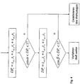
- a corresponding calculation scheme with query is in Fig. 4 specified.
- a warning message is generated and transmitted to a robot control device and / or to an optical and / or acoustic signal generator, in particular a warning lamp, signal lamp, siren, horn, or loudspeaker, if the position and / or Alignment of the robot tool within the tolerance range deviates by a predetermined percentage of the respective reference direction.
- an optical and / or acoustic signal generator in particular a warning lamp, signal lamp, siren, horn, or loudspeaker, if the position and / or Alignment of the robot tool within the tolerance range deviates by a predetermined percentage of the respective reference direction.
- a shutdown and deactivation of the respective robot tool and of the robot is carried out in a fourth step 40 in cooperation with the control device of the robot.
- the reference and / or tolerance values acquired in the process preparation can be changed by means of external and / or internal control devices and / or inputs.
- the first and second process steps can be carried out cyclically continuously or cyclically at discrete time intervals.
- the method ends when leaving a tolerance range and the robot tool is deactivated and / or the method is manually interrupted or terminated.
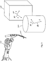
- FIG. 2 an exemplary robot 200 with tool 205 and two predetermined reference directions 210, 220 is shown, each with a tolerance angle 230, 240, wherein the shutdown of the respective robot tool 205 and / or robot 200 when leaving and / or exceeding only one by a tolerance angle 230, 240 spanned tolerance range 250, 260 is performed.
- the working area of the robot 200 can also be subdivided into two or more sub-work areas 310, 320, each having at least one reference direction 330, 340, 350, 360, in which case several locally distributed, different reference directions 330, 350 and / or or tolerance angle can be taken into account, so that the respective partial work areas 310, 320 of the robot 200 can be assigned differently required tool orientations and / or orientations and / or positions.
- the suitable or suitable reference directions 330, 340, 350, 360 and / or references and / or tolerances are automatically determined depending on the position of the robot 200 and / or the robot tool 205 in relation to the respective sub-work area 310, 320 and thus location-dependent and / or or selected in a spatially resolved manner.
- Fig. 4 is a calculation scheme for determining the scalar product DP z of the tool z vector in reference coordinates with the tool z reference vector in reference coordinates, and the scalar product DP x of the tool x vector in reference coordinates with the tool x reference vector in reference coordinates specified , Both scalar products are successively compared with the cosine of the corresponding half cone angle ⁇ , ⁇ . If the scalar product is within the respective range, then the orientation of the tool is within the permissible tolerances. If only one scalar product is outside the corresponding range, the deactivation of the tool follows.
- Fig. 5 shows the calculation scheme of Fig. 4
- the quaternions are first converted into unit vectors and then, as explained above (see Fig. 4 ), processed accordingly.
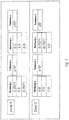
- Fig. 6 is an exemplary system for alignment and position control of a robot tool, wherein a monitoring device 600 with detection unit 610 and processing unit 620 is provided, which cooperates with the control device 630 of the robot 200 and taking into account at least one predetermined reference direction of the robot tool, and at least one predetermined tolerance angle, which, by means of the detection unit 610, automatically determines the alignment of the robot tool and the processing unit 620 compares the determined alignment with the predefinable reference direction and / or with the tolerance values specified by the conical tolerance range and / or when leaving the at least one tolerance range in cooperation with the control device 630 of the robot 200, a shutdown and / or deactivation of respective robot tool 205 causes.
- a monitoring device 600 with detection unit 610 and processing unit 620 is provided, which cooperates with the control device 630 of the robot 200 and taking into account at least one predetermined reference direction of the robot tool, and at least one predetermined tolerance angle, which, by means of the detection unit 610, automatically determines the alignment of the robot tool
- the processing unit 620 stops the movement of the robot 200 when leaving the at least one tolerance range.
- the monitoring device 600 performs the alignment and / or position determination of the robot tool 205 on the basis of measured values relating to the robot axis. and / or motor positions of the robot 200, wherein also the position of the respective robot tool 205 and / or auxiliary means can be determined.
- the monitoring device 600 is configured to generate a warning message and to transmit to the robot control device 630 and / or an optical and / or acoustic signal generator, in particular a warning lamp, signal lamp, siren, horn, or loudspeaker, if the position and / or orientation of the robot tool deviates within the tolerance range by a predeterminable percentage of the respective reference direction.
- an optical and / or acoustic signal generator in particular a warning lamp, signal lamp, siren, horn, or loudspeaker, if the position and / or orientation of the robot tool deviates within the tolerance range by a predeterminable percentage of the respective reference direction.
- At least two reference directions, each with a tolerance angle can be predetermined, wherein the monitoring device 630 causes the shutdown of the respective robot tool 205 when leaving and / or exceeding even a tolerance range spanned by a tolerance angle.
- the monitoring device 600 is set up for the work area of the robot 200 if required and / or specification-dependent subdivided into at least two partial work areas, each with at least one reference direction with tolerance angle, then several locally distributed, different reference directions and / or tolerance angle are taken into account.
- the geometry, size, position and arrangement of the various sub-work areas are freely selectable. If two or more sub-work areas overlap, all valid tolerance ranges must be taken into account and adhered to in the overlap area. This applies to both the system and the method.
- the monitoring device 630 automatically selects the suitable or suitable reference directions and / or references and / or tolerances as a function of the position of the robot 200 and / or the robot tool 205 in relation to the respective sub-work area and thus location-dependent and / or spatially resolved.
- an input device with corresponding input possibilities as in Fig. 7 shown to be provided to detect and / or change reference and / or tolerance values and / or directions, even for multiple sub-work areas.
- the monitoring device determines alignment errors and / or deviations of the robot tool with respect to the respective reference direction according to the method, preferably by scalar product formation and subsequent comparison.
Landscapes
- Engineering & Computer Science (AREA)
- Robotics (AREA)
- Mechanical Engineering (AREA)
- Health & Medical Sciences (AREA)
- General Health & Medical Sciences (AREA)
- Orthopedic Medicine & Surgery (AREA)
- Manipulator (AREA)
- Numerical Control (AREA)
Description
Die Erfindung betrifft ein System sowie ein Verfahren zur Ausrichtungskontrolle eines Roboterwerkzeugs.The invention relates to a system and a method for alignment control of a robot tool.
Industriell eingesetzte Roboter tragen in aller Regel Werkzeuge, wobei es sich sowohl um Prozesswerkzeuge für Bearbeitungs- oder Montagearbeiten, beispielsweise Werkzeuge zum Polieren, Fräsen, Schweißen, Trennen, Lackieren, Kleben, wie insbesondere Schweißzangen oder -pistolen (weld guns), Lackierpistolen, Klebepistolen oder auch Schneidbrenner, als auch um Greifwerkzeuge handeln kann, um vorbestimmte Aufgaben unter Programmsteuerung durch- beziehungsweise auszuführen, Ein solcher Roboter ist in Dokument
Da einige dieser Werkzeuge oder Hilfsmittel im täglichen Gebrauch ein hohes Gefährdungspotential für Mensch und Material in sich tragen, insbesondere durch Emission gefährlicher beziehungsweise gefährdender Mittel oder Medien, wie beispielsweise ein Laserstrahl oder ein Hochdruck-Wasserstrahl, sind im Umgang mit derartigen Werkzeugen besondere sicherheitsrelevante Aspekte und Fragestellungen zu beachten und entsprechende Maßnahmen zur Gefahren- und/oder Schadensminimierung vorzusehen. Dies gilt insbesondere bei Bewegungen des Roboters mit aktiviertem Werkzeug, beispielsweise bei Annäherung des Roboterwerkzeugs an ein zu bearbeitendes Werkstück.Since some of these tools or aids in daily use carry a high hazard potential for people and material in itself, in particular by emission of dangerous or hazardous media or media, such as a laser beam or a high-pressure water jet, are in dealing with such tools special security-relevant aspects and Observe questions and provide appropriate measures to minimize hazards and / or damage. This applies in particular to movements of the robot with an activated tool, for example when approaching the robot tool to a workpiece to be machined.
Auch werden bei bekannten Roboteranordnungen, um Menschen und Material vor fehlerhaften Lagen und/oder Ausrichtungen und/oder Bewegungen des aktivierten Roboterwerkzeuges zu schützen, welche beispielsweise zu einer unkontrollierten Abtastung der Arbeitsumgebung des Roboters mit dem jeweiligen Medium führen können und damit erheblichen Schaden verursachen können, Einfassungen oder Umbauungen der jeweiligen Roboterzelle beziehungsweise des Roboters erforderlich, welche der Energie der Mittel des Roboterwerkzeugs während einer bestimmten Zeit widerstehen können beziehungsweise deren Energie für eine bestimmte Zeit aufnehmen können. Diese Einfassungen oder Umbauungen bedeuten jedoch einen zusätzlichen technischen sowie finanziellen Aufwand und bilden einen wesentlichen Kostenfaktor bei der Installation von Robotern, insbesondere von Industrierobotern.Also, in known robot arrangements to protect people and material from faulty layers and / or alignments and / or movements of the activated robot tool, which can lead to an uncontrolled scanning of the working environment of the robot with the respective medium, for example, and thus can cause considerable damage, Mounts or conversions of the respective robot cell or the robot required, which can withstand the energy of the means of the robot tool for a certain time or their energy for a certain time be able to record. These enclosures or conversions, however, represent an additional technical and financial expense and constitute a significant cost factor in the installation of robots, especially industrial robots.
Daran angelehnt liegt der Erfindung die Aufgabe zugrunde den Installationsaufwand eines Roboters, insbesondere eines Industrieroboters zu minimieren und eine Möglichkeit anzugeben die Orientierung und/oder Ausrichtung eines Roboterwerkzeugs effizient zu kontrollieren.Based on this, the object of the invention is to minimize the installation effort of a robot, in particular of an industrial robot, and to provide a possibility of efficiently controlling the orientation and / or orientation of a robot tool.
Diese Aufgabe wird durch das erfindungsgemäße Verfahren zur Ausrichtungs- und Lagekontrolle eines Roboterwerkzeugs mit den Merkmalen des Anspruch 1 gelöst.This object is achieved by the method according to the invention for alignment and position control of a robot tool having the features of
Ein System zur Ausführung des erfindungsgemäßen Verfahrens sowie vorteilhafte Ausgestaltungen und Weiterbildungen der Erfindung sind in weiteren Ansprüchen und der nachfolgenden Beschreibung angegeben.A system for carrying out the method according to the invention as well as advantageous refinements and developments of the invention are specified in further claims and the following description.
Beim erfindungsgemäßen Verfahren zur Ausrichtungs- und Lagekontrolle eines Roboterwerkzeugs wird unter Berücksichtigung wenigstens einer Referenzrichtung des Roboterwerkzeugs, sowie wenigstens eines vorgebbaren Toleranzwinkels, welcher einen Toleranzbereich, insbesondere einen sich von einem vorbestimmten Ursprung aufweitenden Toleranzbereich, um die wenigstens eine Referenzrichtung des Roboterwerkzeuges aufspannt, mittels Messwerterfassung und -verarbeitung automatisiert die Ausrichtung des Roboterwerkzeuges ermittelt und mit der Referenzrichtung und/oder den durch den, insbesondere kegelförmigen, Toleranzbereich vorgegebenen Toleranzwerten verglichen und bei Verlassen des wenigstens einen Toleranzbereichs eine Abschaltung und/oder Deaktivierung des jeweiligen Roboterwerkzeugs bewirkt.In the method according to the invention for alignment and position control of a robot tool, taking into account at least one reference direction of the robot tool, and at least one predefinable tolerance angle, which spans a tolerance range, in particular a tolerance range widening from a predetermined origin around which at least one reference direction of the robot tool spans, by means of measured value detection and processing automatically determines the orientation of the robot tool and compared with the reference direction and / or the tolerance range specified by the, in particular conical, tolerance range and causes a shutdown and / or deactivation of the respective robot tool when leaving the at least one tolerance range.
In vorteilhafter Ausbildung des Verfahrens wird ein kegelförmiger Toleranzbereich um die wenigstens eine Referenzrichtung des Roboterwerkzeugs aufgespannt. Grundsätzlich sind je nach gewähltem Koordinatensystem aber auch andere Geometrien des wenigstens einen sich aufweitenden Toleranzbereichs möglich, wie beispielsweise bei der Verwendung von Eulerwinkel oder Quaternionen zur Beschreibung der Roboterbewegung, oder bei Verwendung von RPY (Roll Pitch Yaw)-Winkel, welche sich von den Eulerwinkeln insbesondere durch die Wahl der Drehachsen unterscheiden. So kann beispielsweise auch wenigstens ein kegelartiger Toleranzbereich mit elliptischer Grundfläche aufgespannt sein.In an advantageous embodiment of the method, a conical tolerance range is clamped around the at least one reference direction of the robot tool. In principle, depending on the selected coordinate system, however, other geometries of the at least one widening tolerance range are possible, for example when using Euler angles or quaternions for describing the robot movement, or when using RPY (Roll Pitch Yaw) angles, which differ from the Euler angles especially by the choice of the axes of rotation. For example, at least one conical tolerance range with an elliptical base can also be clamped.
Durch die Berücksichtigung individueller Toleranzbereiche für jede Referenzrichtung des Roboterwerkzeugs wird somit ein frühzeitiges, unnötiges Deaktivieren des Roboterwerkzeuges vermieden und eine effiziente Kontrolle der Werkzeugausrichtung ermöglicht.By taking into account individual tolerance ranges for each reference direction of the robot tool, an early, unnecessary deactivation of the robot tool is thus avoided and an efficient control of the tool alignment is made possible.
Bei einer vorteilhaften Weiterbildung des Verfahrens wird bei Verlassen des wenigstens einen Toleranzbereiches nicht nur das entsprechende Roboterwerkzeug abgeschaltet und/oder deaktiviert, sondern vermittels eines geeigneten Steuersignals an den Kontroller des Roboters auch die Bewegung des Roboters gestoppt.In an advantageous development of the method, not only the corresponding robot tool is switched off and / or deactivated when leaving the at least one tolerance range, but also stops the movement of the robot by means of a suitable control signal to the controller of the robot.
Insbesondere verläuft die Referenzrichtung des Roboterwerkzeuges entlang einer Koordinatenachse, beispielsweise der Z-Achse, eines vorbestimmbaren festen Bezugs- und/oder Referenzraums des Roboterarbeitsbereiches, welchem ein vorzugsweise kartesisches Koordinatensystem mit entsprechendem Ursprung zugeordnet ist. Dieses Koordinatensystem entspricht vorzugsweise dem sog. Weltkoordinatensystem. Insbesondere spannt das kartesische Koordinatensystem dabei einen 3-dim Vektorraum auf.In particular, the reference direction of the robot tool runs along a coordinate axis, for example the Z axis, of a predeterminable fixed reference and / or reference space of the robot working area to which a preferably Cartesian coordinate system with a corresponding origin is assigned. This coordinate system preferably corresponds to the so-called world coordinate system. In particular, the Cartesian coordinate system spans a 3-dim vector space.
In einer vorteilhaften Ausgestaltung des Verfahrens wird die Ausrichtungs- und/oder Lagebestimmung des Roboterwerkzeugs mittels Erfassung und Verarbeitung von Messwerten bezüglich der Roboterachsen- und/oder Motorpositionen des Roboters durchgeführt.In an advantageous embodiment of the method, the alignment and / or position determination of the robot tool is carried out by means of detection and processing of measured values with respect to the robot axis and / or motor positions of the robot.
In einer weiteren vorteilhaften Ausgestaltung des Verfahrens wird nicht nur die Ausrichtung oder Lage des jeweiligen Werkzeuges und/oder Hilfsmittels ermittelt, sondern auch dessen Position bestimmt.In a further advantageous embodiment of the method not only the orientation or position of the respective tool and / or auxiliary means is determined, but also determines its position.
In einer vorteilhaften Weiterbildung des Verfahrens wird zusätzlich eine Warnmeldung generiert und zum Roboterkontroll- und/oder -steuerpult und/oder zu einem optischen und/oder akustischen Signalgeber, beispielsweise eine Warnlampe, Signallampe, Sirene, Horn, Lautsprecher, übermittelt wenn die Lage und/oder Ausrichtung des Roboterwerkzeuges innerhalb des Toleranzbereiches um einen vorbestimmten Prozentanteil von der Referenzrichtung abweicht.In an advantageous development of the method, a warning message is additionally generated and sent to the robot control and / or control desk and / or to an optical and / or acoustic signal generator, for example a warning lamp, signal lamp, Siren, horn, speaker, transmitted when the position and / or orientation of the robot tool within the tolerance range deviates by a predetermined percentage of the reference direction.
In einer weiteren vorteilhaften Ausgestaltung des Verfahrens werden wenigstens zwei Referenzrichtungen mit je einem Toleranzwinkel vorgegeben, wobei die Abschaltung des jeweiligen Hilfsmittels und/oder Werkzeugs bei Verlassen beziehungsweise Überschreiten auch nur eines durch den Toleranzwinkel aufgespannten Toleranzbereiches erfolgt. So kann beispielsweise eine zweite Werkzeugreferenzrichtung, wie die X-Richtung des festen Bezugssystems, gemeinsam mit einem zweiten Toleranzwinkel, der beispielsweise einen zweiten Kegel aufspannt, angegeben und berücksichtigt werden.In a further advantageous embodiment of the method, at least two reference directions are specified, each with a tolerance angle, wherein the shutdown of the respective aid and / or tool when leaving or exceeding only a tolerance range spanned by the tolerance angle occurs. Thus, for example, a second tool reference direction, such as the X direction of the fixed reference system, together with a second tolerance angle, which spans, for example, a second cone, can be specified and taken into account.
In einer weiteren Ausgestaltung des Verfahrens ist vorgesehen den Arbeitsbereich des Roboters in wenigstens zwei Teilarbeitsbereiche mit jeweils wenigstens einer Referenzrichtung mit Toleranzwinkel zu untergliedern, wodurch eine verfahrensgemäße Berücksichtigung auch mehrerer lokal verteilter, unterschiedlicher Referenzrichtungen und/oder Toleranzwinkel, wie beispielsweise bei einer komplexen Werkstückgeometrie erforderlich, ermöglicht wird. Demgemäß werden verschieden erforderliche Werkzeugorientierungen beziehungsweise -ausrichtungen oder -lagen den jeweiligen Teilarbeitsbereichen des Roboters zugeordnet.In a further embodiment of the method, it is provided to subdivide the working area of the robot into at least two partial work areas, each with at least one reference direction with tolerance angle, whereby a process-oriented consideration also several locally distributed, different reference directions and / or tolerance angle, as required for example in a complex workpiece geometry, is possible. Accordingly, variously required tool orientations or alignments are assigned to the respective sub-work areas of the robot.
Verfahrensgemäß werden dann automatisiert die passenden oder geeigneten Referenzrichtungen bzw. Referenzen und/oder Toleranzen in Abhängigkeit der Position des Roboters beziehungsweise des Roboterwerkzeugs in Relation zum jeweiligen Teilarbeitsbereich und damit ortsabhängig bzw. ortsaufgelöst selektiert.According to the method, the suitable or suitable reference directions or references and / or tolerances are then automatically selected in dependence on the position of the robot or of the robot tool in relation to the respective sub-work area and thus location-dependent or spatially resolved.
In einer weiteren vorteilhaften Ausgestaltung des Verfahrens sind die Referenz- und/oder Toleranzwerte durch externe und/oder interne Kontrolleinrichtungen und/oder Eingaben änderbar und/oder vorgebbar.In a further advantageous embodiment of the method, the reference and / or tolerance values can be changed and / or predefined by external and / or internal control devices and / or inputs.
In einer vorteilhaften Weiterbildung des Verfahrens werden die Ausrichtungsfehler des Roboterwerkzeugs und/oder -hilfsmittels in Bezug auf die jeweilige Referenzrichtung ermittelt, indem das Skalarprodukt des Werkzeug-z-Vektors in Referenzkoordinaten mit dem Werkzeug-z-Referenzvektor in Referenzkoordinaten, und/oder das Skalarprodukt des Werkzeug-x-Vektors in Referenzkoordinaten mit dem Werkzeug-x-Referenzvektor in Referenzkoordinaten gebildet werden. Dabei ist festzustellen, dass jedem Werkzeug ein bewegliches, vorzugsweise kartesisches oder rechtwinkliges Koordinatensystem mit den drei Koordinatenachsen x,y,z bzw. diesen entsprechenden, die Richtung angebenden Vektoren x,y,z zugeordnet ist, welches der Bewegung bzw. Ausrichtung des Roboterwerkzeugs folgt und diese, in Relation zum Referenzkoordinatensystem, beschreibt. Vorzugsweise werden dabei alle Vektoren als Einheitsvektoren angegeben und/oder über ihren Betrag entsprechend normiert.In an advantageous development of the method, the alignment errors of the robot tool and / or auxiliary means with respect to the respective reference direction are determined by the scalar product of the tool z vector in reference coordinates the tool z reference vector in reference coordinates, and / or the scalar product of the tool x vector in reference coordinates with the tool x reference vector are formed in reference coordinates. It should be noted that each tool is a movable, preferably Cartesian or rectangular coordinate system with the three coordinate axes x, y, z or this corresponding, the direction indicating vectors x, y, z is assigned, which follows the movement or orientation of the robot tool and describes them in relation to the reference coordinate system. In this case, all vectors are preferably specified as unit vectors and / or normalized according to their amount.
Das Skalarprodukt zweier Einheitsvektoren ergibt den Cosinus des kleinsten eingeschlossenen Winkels zwischen beiden Vektoren, der dem halben Öffnungswinkel des Kegels entspricht, der gebildet wird, wenn der der aktuellen Ausrichtung entsprechende Vektor um den Vektor der vorgegebenen Referenzrichtung rotiert und/oder präzessiert.The scalar product of two unit vectors gives the cosine of the smallest included angle between both vectors, which corresponds to half the opening angle of the cone formed when the vector corresponding to the current orientation rotates and / or precesses around the vector of the given reference direction.
Verfahrensgemäß werden somit bei jeweils abrufbar gespeichertem Cosinus des Winkels zwischen Referenzvektor und entsprechendem Toleranzvektor und/oder bei abrufbar gespeichertem Cosinus des halben Öffnungswinkels des kegelförmigen Toleranzbereichs keine weiteren zeitaufwendigen trigonometrischen Operationen und/oder Berechnungen erforderlich.Thus, according to the method, no further time-consuming trigonometric operations and / or calculations are required when the cosinus of the angle between the reference vector and the corresponding tolerance vector and / or cosinus of the half-opening angle of the conical tolerance range which can be stored is retrievably stored.
In einer alternativen Ausgestaltung der Erfindung erfolgt die Angabe der Werkzeugausrichtung beziehungsweise -lage in Quaternionen, wobei es sich bei Quaternionen um eine vierdimensionale Divisionsalgebra über dem Körper der reellen Zahlen mit einer nicht kommutativen Multiplikation handelt. Als vierdimensionale reelle Algebra bilden die Quaternionen einen vierdimensionalen reellen Vektorraum. Demgemäß ist jedes Quaternion durch vier reelle Komponenten x 0,x 1,x 2,x 3 eindeutig bestimmt. Als Basiselemente dieses Vektorraums werden vier Elemente mit der Länge 1 gewählt, die senkrecht aufeinander stehen; sie werden mit 1,i,j,k bezeichnet. Die Linearkombination der vier Komponenten mit den vier Basiselementen lautet demgemäß ![]()
![]()
![]()
![]()
Dementsprechend werden die Quaternionen zunächst in Einheitsvektoren konvertiert und dann, wie vorstehend erläutert, entsprechend weiterverarbeitet.Accordingly, the quaternions are first converted into unit vectors and then further processed as explained above.
In einer vorteilhaften Weiterbildung der Erfindung ergeht eine Rückmeldung falls es sich bei den angegebenen und/oder konvertierten Vektoren nicht um Einheitsvektoren, handelt und/oder der angegebene Z-Vektor nicht senkrecht zum x-Vektor steht.In an advantageous development of the invention, a feedback is issued if the indicated and / or converted vectors are not unit vectors, and / or the specified Z vector is not perpendicular to the x vector.
Weitere Möglichkeiten die Werkzeugreferenzrichtungen anzugeben bedienen sich beispielsweise Lehrmethoden (teaching methods), Offline Programmierung und/oder virtueller Realitäten.Other options for specifying tool reference directions include, for example, teaching methods, offline programming and / or virtual realities.
Das erfindungsgemäße System zur Ausrichtungs- und Lagekontrolle eines Roboterwerkzeugs umfasst eine Überwachungseinrichtung mit einer Messwerterfassungseinheit und einer Verarbeitungseinheit, wobei die Überwachungseinrichtung über wenigstens eine Schnittstelle mit der Kontrolleinrichtung des Roboters zusammenwirkt und unter Berücksichtigung wenigstens einer vorgebbaren Referenzrichtung des Roboterwerkzeugs, sowie wenigstens eines vorgebbaren Toleranzwinkels, welcher insbesondere einen kegelförmigen Toleranzbereich um die wenigstens eine Referenzrichtung des Roboterwerkzeuges aufspannt, mittels der Messwerterfassungseinheit anhand erfasster Messdaten automatisiert die Ausrichtung des Roboterwerkzeuges ermittelt und die Verarbeitungseinheit die ermittelte Ausrichtung mit der Referenzrichtung und/oder den durch den insbesondere kegelförmigen Toleranzbereich vorgegebenen Toleranzwerten vergleicht und bei Verlassen des wenigstens einen Toleranzbereichs im Zusammenwirken mit der Kontrolleinrichtung des Roboters eine Abschaltung und/oder Deaktivierung des jeweiligen Roboterwerkzeugs bewirkt.The system according to the invention for alignment and position control of a robot tool comprises a monitoring device with a measured value acquisition unit and a processing unit, wherein the monitoring device interacts with the control device of the robot via at least one interface and taking into account at least one predeterminable reference direction of the robot tool and at least one predefinable tolerance angle in particular a conical tolerance range spans around the at least one reference direction of the robot tool, automatically determines the alignment of the robot tool by means of the measured value acquisition unit based on acquired measurement data and the processing unit compares the determined alignment with the reference direction and / or the tolerance values predetermined by the particular conical tolerance range and upon exiting at least one tolerance in interaction with the cont rolling device of the robot causes a shutdown and / or deactivation of the respective robot tool.
Die weitere Darlegung der Erfindung sowie vorteilhafter Ausgestaltungen erfolgt anhand einiger Figuren und Ausführungsbeispiele.The further explanation of the invention and advantageous embodiments will be made with reference to some figures and embodiments.
Es zeigen
-
Fig. 1 beispielhaft ausgebildeter Verfahrensablauf zur Ausrichtungs- und Lagekontrolle eines Roboterwerkzeugs, -
Fig. 2 beispielhafter Roboter mit Werkzeug und zwei Referenzrichtungen mit je einem Toleranzwinkel, -
Fig. 3 beispielhafter Roboter mit Werkzeug mit untergliedertem Arbeitsbereich in zwei Teilarbeitsbereiche mit je zwei vorgegebenen Referenzrichtungen, -
Fig. 4 beispielhaftes Berechnungsschema zur Bestimmung von Ausrichtungsfehlern, -
Fig. 5 beispielhaftes Berechnungsschema zur Bestimmung von Ausrichtungsfehlern gemäßFig. 4 , jedoch unter Verwendung von Quaternionen, -
Fig. 6 beispielhaft ausgebildetes System zur Ausrichtungs- und Lagekontrolle eines Roboterwerkzeugs, -
Fig. 7 beispielhafte Eingabemöglichkeit.
-
Fig. 1 exemplary trained procedure for alignment and position control of a robot tool, -
Fig. 2 exemplary robot with tool and two reference directions, each with a tolerance angle, -
Fig. 3 exemplary robot with tool with subdivided work area into two sub work areas with two predetermined reference directions, -
Fig. 4 exemplary calculation scheme for determining alignment errors, -
Fig. 5 exemplary calculation scheme for determining alignment errors according toFig. 4 but using quaternions, -
Fig. 6 exemplary trained system for alignment and position control of a robot tool, -
Fig. 7 exemplary input option.
In
Die Referenzrichtung des Roboterwerkzeuges verläuft dabei vorzugsweise entlang einer Koordinatenachse, eines vorbestimmbaren festen Bezugs- und/oder Referenzraums des Roboterarbeitsbereiches. Dem festen Referenzraum wird dabei ein kartesisches Koordinatensystem zugrunde gelegt welches einen 3-dim Vektorraum aufspannt.The reference direction of the robot tool preferably runs along a coordinate axis, a predeterminable fixed reference and / or reference space of the robot working area. The fixed reference space is based on a Cartesian coordinate system which spans a 3-dim vector space.
In einem zweiten Verfahrensschritt 20 wird die ermittelte Ausrichtung mit der jeweilig vorbestimmten Referenzrichtung und/oder mit den durch den kegelförmigen Toleranzbereich vorgegebenen Toleranzwerten verglichen.In a
Dabei werden Ausrichtungsfehler und/oder -abweichungen des Roboterwerkzeugs in Bezug auf die jeweilige Referenzrichtung vorzugsweise dahingehend ermittelt, dass das Skalarprodukt des Werkzeug-z-Vektors in Referenzkoordinaten mit dem Werkzeug-z-Referenzvektor in Referenzkoordinaten, und/oder das Skalarprodukt des Werkzeug-x-Vektors in Referenzkoordinaten mit dem Werkzeug-x-Referenzvektor in Referenzkoordinaten gebildet werden. Dabei dem Werkzeug ein bewegliches, kartesisches oder rechtwinkliges Koordinatensystem mit den drei Koordinatenachsen x,y,z bzw. diesen entsprechenden, die Richtung angebenden Vektoren X,Y,Z zugeordnet, welches der Bewegung bzw. Ausrichtung des Roboterwerkzeugs folgt und diese, in Relation zum Referenzkoordinatensystem X,Y,Z, beschreibt. Vorzugsweise werden dabei alle Vektoren als Einheitsvektoren angegeben und/oder über ihren Betrag entsprechend normiert. Das Skalarprodukt zweier Einheitsvektoren ergibt den Cosinus des kleinsten eingeschlossenen Winkels zwischen beiden Vektoren, der dem halben Öffnungswinkel des Kegels entspricht, der gebildet wird, wenn der der aktuellen Ausrichtung entsprechende Vektor um den Vektor der vorgegebenen Referenzrichtung rotiert und/oder präzessiert.In this case, alignment errors and / or deviations of the robot tool with respect to the respective reference direction are preferably determined in such a way that the scalar product of the tool z vector in reference coordinates with the tool z reference vector in reference coordinates, and / or the scalar product of the tool x Vector in reference coordinates with the tool x reference vector in reference coordinates. In this case, the tool is assigned a movable, Cartesian or rectangular coordinate system with the three coordinate axes x, y, z or these vectors indicating the direction X, Y, Z, which follows the movement or orientation of the robot tool and these, in relation to Reference coordinate system X, Y, Z describes. In this case, all vectors are preferably specified as unit vectors and / or normalized according to their amount. The scalar product of two unit vectors gives the cosine of the smallest included angle between both vectors, which corresponds to half the opening angle of the cone formed when the vector corresponding to the current orientation rotates and / or precesses around the vector of the given reference direction.
Vorteilhaft ist der Cosinus des Winkels zwischen Referenzvektor und entsprechendem Toleranzvektor und/oder der Cosinus des halben Öffnungswinkels des kegelförmigen Toleranzbereichs in einem Zwischenschritt ermittel- und speicherbar, so dass er im Laufe des Verfahrens jederzeit abgerufen werden kann und demgemäß keine weiteren zeitaufwendigen trigonometrischen Operationen und/oder Berechnungen erforderlich werden. Ein entsprechendes Berechnungsschema mit Abfrage ist in
In einem dritten Verfahrensschritt 30 wird eine Warnmeldung generiert und zu einer Roboterkontrolleinrichtung und/oder -und/oder zu einem optischen und/oder akustischen Signalgeber, insbesondere eine Warnlampe, Signallampe, Sirene, Horn, oder Lautsprecher, übermittelt, wenn die Lage und/oder Ausrichtung des Roboterwerkzeugs innerhalb des Toleranzbereiches um einen vorbestimmten Prozentanteil von der jeweiligen Referenzrichtung abweicht.In a
Wird wenigstens ein Toleranzbereichs verlassen, so wird in einem vierten Schritt 40 im Zusammenwirken mit der Kontrolleinrichtung des Roboters eine Abschaltung und Deaktivierung des jeweiligen Roboterwerkzeugs sowie des Roboters durchgeführt.If at least one tolerance range is left, a shutdown and deactivation of the respective robot tool and of the robot is carried out in a
Die verfahrensvorbereitend erfassten Referenz- und/oder Toleranzwerte sind dabei vermittels externer und/oder interner Kontrolleinrichtungen und/oder Eingaben änderbar.The reference and / or tolerance values acquired in the process preparation can be changed by means of external and / or internal control devices and / or inputs.
Der erste und zweite Verfahrensschritt können dabei zyklisch kontinuierlich oder zyklisch in diskreten Zeitabständen durchgeführt werden.The first and second process steps can be carried out cyclically continuously or cyclically at discrete time intervals.
Das Verfahren endet wenn ein Toleranzbereich verlassen und das Roboterwerkzeug deaktiviert wird und/oder das Verfahren manuell unterbrochen beziehungsweise beendet wird.The method ends when leaving a tolerance range and the robot tool is deactivated and / or the method is manually interrupted or terminated.
In
In
In
In
In
Auch sind wenigstens zwei Referenzrichtungen mit je einem Toleranzwinkel vorgebbar, wobei die Überwachungseinrichtung 630 die Abschaltung des jeweiligen Roboterwerkzeugs 205 bei Verlassen und/oder Überschreiten auch nur eines durch einen Toleranzwinkel aufgespannten Toleranzbereiches bewirkt.Also, at least two reference directions, each with a tolerance angle can be predetermined, wherein the
Die Überwachungseinrichtung 600 ist dafür eingerichtet den Arbeitsbereich des Roboters 200 bei Bedarf und/oder vorgabenabhängig in wenigstens zwei Teilarbeitsbereiche mit jeweils wenigstens einer Referenzrichtung mit Toleranzwinkel untergliedert, wobei dann mehrere lokal verteilte, unterschiedliche Referenzrichtungen und/oder Toleranzwinkel berücksichtigt sind.The
Die Geometrie, Größe, Lage und Anordnung der verschiedenen Teilarbeitsbereiche sind dabei frei wählbar. Überlappen zwei oder mehrere Teilarbeitsbereiche so sind im Überlappungsbereich alle gültigen Toleranzbereiche zu berücksichtigen und einzuhalten. Dies gilt sowohl für das System als auch das Verfahren.The geometry, size, position and arrangement of the various sub-work areas are freely selectable. If two or more sub-work areas overlap, all valid tolerance ranges must be taken into account and adhered to in the overlap area. This applies to both the system and the method.
Die Überwachungseinrichtung 630 selektiert automatisch die passenden oder geeigneten Referenzrichtungen und/oder Referenzen und/oder Toleranzen in Abhängigkeit der Position des Roboters 200 und/oder des Roboterwerkzeugs 205 in Relation zum jeweiligen Teilarbeitsbereich und damit ortsabhängig und/oder ortsaufgelöst .The
Des Weiteren kann eine Eingabevorrichtung mit entsprechenden Eingabemöglichkeiten, wie in
Die Überwachungseinrichtung ermittelt Ausrichtungsfehler und/oder-abweichungen des Roboterwerkzeugs in Bezug auf die jeweilige Referenzrichtung verfahrensgemäß, vorzugsweise durch Skalarproduktbildung und anschließenden Vergleich.The monitoring device determines alignment errors and / or deviations of the robot tool with respect to the respective reference direction according to the method, preferably by scalar product formation and subsequent comparison.
Claims (19)
- Method for alignment, position and orientation monitoring of a robot tool, wherein the alignment of the robot tool is determined, is compared with the reference direction and/or with tolerance values which are predetermined by the tolerance band, and/or the respective robot tool is disconnected and/or deactivated on leaving the at least one tolerance band, automatically by means of measured-value recording and processing and taking account of at least one predeterminable reference direction of the robot tool, and at least one predeterminable tolerance angle, which defines a tolerance band around the at least one reference direction of the robot tool, characterized in that at least two reference directions are predetermined, each having a tolerance angle, with the robot tool being disconnected even on leaving and/or exceeding just one tolerance band which is defined by a tolerance angle.
- Method according to Claim 1, characterized in that a tolerance band widening from a predetermined origin is defined around the at least one reference direction of the robot tool by the at least one predeterminable tolerance angle.
- Method according to either of Claims 1 and 2, characterized in that at least one conical tolerance band is defined around the at least one reference direction of the robot tool by the at least one predeterminable tolerance angle.
- Method according to one of the preceding claims, characterized in that the reference direction of the robot tool runs along a coordinate axis, of a predeterminable fixed reference space of the robot working area.
- Method according to Claim 4, characterized in that the fixed reference space is based on a Eulerian coordinate system or a coordinate system based on RPY angles.
- Method according to one of the preceding claims, characterized in that the working area of the robot is subdivided into at least two working area elements each having at least one reference direction with a tolerance angle, with a plurality of locally distributed, different reference directions and/or tolerance angles then being taken into account.
- Method according to Claim 6, characterized in that various required tool orientations and/or alignments and/or positions are associated with the respective working area elements of the robot.
- Method according to one of Claims 6 or 7, characterized in that the appropriate or suitable reference directions and/or references and/or tolerances are selected automatically as a function of the position of the robot and/or of the robot tool in relation to the respective working area element, and therefore as a function of the position and/or on a position-resolved basis.
- System for alignment, position and orientation monitoring of a robot tool, with a monitoring device being provided which has a recording unit and a processing unit, interacts with the checking device of the robot and automatically determines the alignment of the robot tool by means of the recording unit, taking into account at least one predeterminable reference direction of the robot tool and at least one predeterminable tolerance angle which defines a tolerance band around the at least one reference direction of the robot tool and the processing unit compares the determined alignment with the predeterminable reference direction and/or with the tolerance values predetermined by the defined tolerance band, and/or, in conjunction with the checking device of the robot, disconnects and/or deactivates the respective robot tool on leaving the at least one tolerance band, characterized in that at least two reference directions are predetermined, each having a tolerance angle, with the robot tool being disconnected by the monitoring device even on leaving and/or exceeding just one tolerance band which is defined by a tolerance angle.
- System according to Claim 9, characterized in that a tolerance band widening from a predetermined origin, in particular conically formed, is defined around the at least one reference direction of the robot tool by the at least one predeterminable tolerance angle.
- System according to either of Claims 9 and 10, characterized in that at least one conical tolerance band is defined around the at least one reference direction of the robot tool by the at least one predeterminable tolerance angle.
- System according to one of Claims 9 to 11, characterized in that the reference direction of the robot tool runs along a coordinate axis, of a predeterminable fixed reference space of the robot working area.
- System according to one of Claims 9 to 12, characterized in that the fixed reference space is based on a Cartesian coordinate system and/or this coordinate system defines a three-dimensional vector space.
- System according to one of Claims 9 to 13, characterized in that the fixed reference space is based on a Eulerian coordinate system or a coordinate system based on RPY angles.
- System according to one of Claims 9 to 14, characterized in that the monitoring device generates a warning message and transmits this to the robot monitoring device and/or to an optical and/or acoustic signal transmitter which is provided for this purpose, in particular a warning lamp, signal lamp, siren, horn, or loudspeaker, if the position and orientation and/or alignment of the robot tool deviates by a predeterminable percentage component from the respective reference direction within the tolerance band.
- System according to one of Claims 9 to 15, characterized in that the monitoring device subdivides the working area of the robot, depending on the requirement, into at least two working area elements each having at least one reference direction with a tolerance angle, with a plurality of locally distributed, different reference directions and/or tolerance angles then being taken into account.
- System according to Claim 16, characterized in that various required tool orientations and/or alignments and/or positions are associated with the respective working area elements of the robot.
- System according to one of Claims 16 or 17, characterized in that the monitoring device automatically selects the appropriate or suitable reference directions and/or references and/or tolerances as a function of the position of the robot and/or of the robot tool in relation to the respective working area element, and therefore as a function of the position and/or on a position-resolved basis.
- System according to one of the preceding Claims 9 to 18, characterized in that the monitoring device determines alignment errors and/or discrepancies of the robot tool with respect to the respective reference direction by in each case forming the scalar product of the respective tool vector in reference coordinates multiplied by the tool reference vector in reference coordinates and/or by comparing it with the cosine of half the opening angle of the conical tolerance band associated with the respective reference direction, and/or the cosine of the angle between the reference vector and the corresponding tolerance vector.
Applications Claiming Priority (2)
| Application Number | Priority Date | Filing Date | Title |
|---|---|---|---|
| DE102005061618.6A DE102005061618B4 (en) | 2005-12-21 | 2005-12-21 | System and method for alignment and position control of a robot tool |
| PCT/EP2006/010945 WO2007079812A1 (en) | 2005-12-21 | 2006-11-15 | System and method for aligning and for controlling the position of a robot tool |
Publications (2)
| Publication Number | Publication Date |
|---|---|
| EP1965955A1 EP1965955A1 (en) | 2008-09-10 |
| EP1965955B1 true EP1965955B1 (en) | 2018-11-07 |
Family
ID=37890889
Family Applications (1)
| Application Number | Title | Priority Date | Filing Date |
|---|---|---|---|
| EP06818547.9A Active EP1965955B1 (en) | 2005-12-21 | 2006-11-15 | System and method for aligning and for controlling the position of a robot tool |
Country Status (5)
| Country | Link |
|---|---|
| US (1) | US8548628B2 (en) |
| EP (1) | EP1965955B1 (en) |
| CN (1) | CN101341008B (en) |
| DE (1) | DE102005061618B4 (en) |
| WO (1) | WO2007079812A1 (en) |
Families Citing this family (15)
| Publication number | Priority date | Publication date | Assignee | Title |
|---|---|---|---|---|
| DE102008030774B4 (en) | 2008-06-28 | 2013-03-07 | Sikora Gmbh | Method and device for the safety-oriented control of a material processing device |
| JP5425006B2 (en) * | 2010-07-12 | 2014-02-26 | 株式会社神戸製鋼所 | Jig used to derive the robot tool vector |
| AT514345B1 (en) * | 2013-05-22 | 2015-02-15 | Bernecker & Rainer Ind Elektronik Gmbh | Safety monitoring of a serial kinematics |
| US9205560B1 (en) * | 2013-06-24 | 2015-12-08 | Redwood Robotics, Inc. | System and method for failure detection of a robot actuator |
| JP6252273B2 (en) * | 2014-03-19 | 2017-12-27 | 株式会社デンソーウェーブ | Robot control method and robot control device |
| JP6281351B2 (en) * | 2014-03-19 | 2018-02-21 | 株式会社デンソーウェーブ | Robot control method and robot control device |
| JP6252278B2 (en) * | 2014-03-20 | 2017-12-27 | 株式会社デンソーウェーブ | Robot control method and robot control device |
| DE102014226162A1 (en) * | 2014-12-17 | 2016-06-23 | Robert Bosch Gmbh | TOOL AND METHOD FOR TREATING A WORKPIECE WITH A TOOL ELEMENT OF A TOOL |
| DE102015219369A1 (en) * | 2015-10-07 | 2017-04-13 | Bayerische Motoren Werke Aktiengesellschaft | Safety device for a jet processing device and method |
| CN105563482A (en) * | 2015-12-01 | 2016-05-11 | 珞石(北京)科技有限公司 | Rotation movement planning method for end effector of industrial robot |
| JP6348101B2 (en) * | 2015-12-17 | 2018-06-27 | ファナック株式会社 | Control device with gap control shaft drop prevention function considering workpiece tilt |
| CN105599240B (en) * | 2016-01-12 | 2017-08-25 | 重庆世纪精信实业(集团)有限公司 | Manipulator of injection machine is directed at system and method |
| CN105739507B (en) * | 2016-04-29 | 2018-11-20 | 昆山华恒机器人有限公司 | A kind of optimum path planning method of robot anticollision |
| US11185987B2 (en) * | 2019-04-26 | 2021-11-30 | Invia Robotics, Inc. | Isolated and environmental anomaly detection and correction using a distributed set of robots |
| CN110675683A (en) * | 2019-09-26 | 2020-01-10 | 东方航空技术有限公司 | VR-based flight line winding inspection training method and device |
Citations (2)
| Publication number | Priority date | Publication date | Assignee | Title |
|---|---|---|---|---|
| WO2001076830A1 (en) * | 2000-04-10 | 2001-10-18 | Abb Ab | Pathcorrection for an industrial robot |
| EP1591209A2 (en) * | 2004-04-30 | 2005-11-02 | KUKA Roboter GmbH | Method of controlling a machine, in particular an industrial robot |
Family Cites Families (11)
| Publication number | Priority date | Publication date | Assignee | Title |
|---|---|---|---|---|
| JPH0319789A (en) * | 1989-06-14 | 1991-01-28 | Fanuc Ltd | Control method for laser robot |
| JP2741094B2 (en) | 1990-06-26 | 1998-04-15 | 松下電器産業株式会社 | Control method of articulated robot |
| US6377906B1 (en) * | 2000-02-03 | 2002-04-23 | Independence Technology, L.L.C. | Attitude estimation in tiltable body using modified quaternion data representation |
| JP4198861B2 (en) * | 2000-03-23 | 2008-12-17 | 東芝機械株式会社 | Correction method of machine error at spindle head of multi-axis machine tool |
| US6819974B1 (en) * | 2000-03-29 | 2004-11-16 | The Boeing Company | Process for qualifying accuracy of a numerically controlled machining system |
| JP3808321B2 (en) * | 2001-04-16 | 2006-08-09 | ファナック株式会社 | Robot controller |
| DE10163392B4 (en) | 2001-12-21 | 2007-06-28 | Audi Ag | Motion-controlled tool with safety shutdown |
| US7283889B2 (en) * | 2003-02-19 | 2007-10-16 | Fanuc Ltd | Numerical control device, and numerical control method |
| DE102004026185A1 (en) | 2004-05-28 | 2005-12-22 | Kuka Roboter Gmbh | Method and apparatus for operating a machine, such as a multi-axis industrial robot |
| CN1803102A (en) * | 2005-12-02 | 2006-07-19 | 北京航空航天大学 | Constrained operation programming method based on medicinal image predisplayed puncture trail |
| US8024068B2 (en) * | 2006-08-04 | 2011-09-20 | Hurco Companies, Inc. | Machine tool control system |
-
2005
- 2005-12-21 DE DE102005061618.6A patent/DE102005061618B4/en active Active
-
2006
- 2006-11-15 CN CN200680048453.5A patent/CN101341008B/en active Active
- 2006-11-15 US US12/158,605 patent/US8548628B2/en active Active
- 2006-11-15 EP EP06818547.9A patent/EP1965955B1/en active Active
- 2006-11-15 WO PCT/EP2006/010945 patent/WO2007079812A1/en active Application Filing
Patent Citations (2)
| Publication number | Priority date | Publication date | Assignee | Title |
|---|---|---|---|---|
| WO2001076830A1 (en) * | 2000-04-10 | 2001-10-18 | Abb Ab | Pathcorrection for an industrial robot |
| EP1591209A2 (en) * | 2004-04-30 | 2005-11-02 | KUKA Roboter GmbH | Method of controlling a machine, in particular an industrial robot |
Also Published As
| Publication number | Publication date |
|---|---|
| CN101341008A (en) | 2009-01-07 |
| US20090076654A1 (en) | 2009-03-19 |
| DE102005061618B4 (en) | 2018-12-27 |
| US8548628B2 (en) | 2013-10-01 |
| DE102005061618A1 (en) | 2007-06-28 |
| EP1965955A1 (en) | 2008-09-10 |
| CN101341008B (en) | 2015-08-19 |
| WO2007079812A1 (en) | 2007-07-19 |
Similar Documents
| Publication | Publication Date | Title |
|---|---|---|
| EP1965955B1 (en) | System and method for aligning and for controlling the position of a robot tool | |
| EP3013537B2 (en) | Method and system for programming a robot | |
| EP2285537B1 (en) | Device and method for the computer-assisted generation of a manipulator track | |
| DE102015105687B4 (en) | robot | |
| DE102010036499A1 (en) | Tool vector display device for a machine tool with a rotation axis | |
| DE102013106076A1 (en) | Toolpath display unit for displaying the tool vector of a machine tool | |
| DE102015202616A1 (en) | Method for editing the surface of a three-dimensional object | |
| DE102015015093A1 (en) | Robot programming device for instructing a robot for machining | |
| EP3221094B1 (en) | Method and system for correcting a processing path of a robot-guided tool | |
| EP2298487A2 (en) | Method and device for operating an additional tool axis of a tool controlled by a manipulator | |
| DE102017120221A1 (en) | Control unit, work control device, multi-axis motion control device and drive control device | |
| DE102012022190B4 (en) | Inverse kinematics | |
| EP3441200A1 (en) | Referencing method and device for industrial robots | |
| EP1302828B1 (en) | Program control system and method for controlling a coating plant | |
| EP3168701B1 (en) | Method for representing the processing in a machine tool | |
| DE112021001173T5 (en) | Deburring device and control system | |
| DE102019120157B3 (en) | Verification of a mass model of a robot manipulator | |
| DE102006036490A1 (en) | Programmable handling device e.g. robot, controlling method for production system, involves moving component e.g. arm, relative to another component based on movement of construction model of virtual image of former component | |
| EP1459855A2 (en) | Method and device for improving the positioning accuracy of a machining robot | |
| DE102015200319A1 (en) | Einmessverfahren from combination of pre-positioning and manual guidance | |
| DE102009040194B4 (en) | Method for force control | |
| EP0977101A1 (en) | Flexible manufacturing system and control method | |
| DE102020006839A1 (en) | System and method for manual training of a robotic manipulator | |
| EP3711909A2 (en) | Method for performing at least one activity process using a robot | |
| DE102019130008B4 (en) | ACTIVITY PROGRAM CREATION INSTALLATION |
Legal Events
| Date | Code | Title | Description |
|---|---|---|---|
| PUAI | Public reference made under article 153(3) epc to a published international application that has entered the european phase |
Free format text: ORIGINAL CODE: 0009012 |
|
| 17P | Request for examination filed |
Effective date: 20080613 |
|
| AK | Designated contracting states |
Kind code of ref document: A1 Designated state(s): AT BE BG CH CY CZ DE DK EE ES FI FR GB GR HU IE IS IT LI LT LU LV MC NL PL PT RO SE SI SK TR |
|
| DAX | Request for extension of the european patent (deleted) | ||
| 17Q | First examination report despatched |
Effective date: 20161202 |
|
| GRAP | Despatch of communication of intention to grant a patent |
Free format text: ORIGINAL CODE: EPIDOSNIGR1 |
|
| INTG | Intention to grant announced |
Effective date: 20180828 |
|
| GRAS | Grant fee paid |
Free format text: ORIGINAL CODE: EPIDOSNIGR3 |
|
| GRAA | (expected) grant |
Free format text: ORIGINAL CODE: 0009210 |
|
| AK | Designated contracting states |
Kind code of ref document: B1 Designated state(s): AT BE BG CH CY CZ DE DK EE ES FI FR GB GR HU IE IS IT LI LT LU LV MC NL PL PT RO SE SI SK TR |
|
| REG | Reference to a national code |
Ref country code: GB Ref legal event code: FG4D Free format text: NOT ENGLISH |
|
| REG | Reference to a national code |
Ref country code: CH Ref legal event code: EP Ref country code: AT Ref legal event code: REF Ref document number: 1061510 Country of ref document: AT Kind code of ref document: T Effective date: 20181115 |
|
| REG | Reference to a national code |
Ref country code: IE Ref legal event code: FG4D Free format text: LANGUAGE OF EP DOCUMENT: GERMAN |
|
| REG | Reference to a national code |
Ref country code: DE Ref legal event code: R096 Ref document number: 502006016095 Country of ref document: DE |
|
| REG | Reference to a national code |
Ref country code: NL Ref legal event code: MP Effective date: 20181107 |
|
| REG | Reference to a national code |
Ref country code: LT Ref legal event code: MG4D |
|
| PG25 | Lapsed in a contracting state [announced via postgrant information from national office to epo] |
Ref country code: ES Free format text: LAPSE BECAUSE OF FAILURE TO SUBMIT A TRANSLATION OF THE DESCRIPTION OR TO PAY THE FEE WITHIN THE PRESCRIBED TIME-LIMIT Effective date: 20181107 Ref country code: FI Free format text: LAPSE BECAUSE OF FAILURE TO SUBMIT A TRANSLATION OF THE DESCRIPTION OR TO PAY THE FEE WITHIN THE PRESCRIBED TIME-LIMIT Effective date: 20181107 Ref country code: LV Free format text: LAPSE BECAUSE OF FAILURE TO SUBMIT A TRANSLATION OF THE DESCRIPTION OR TO PAY THE FEE WITHIN THE PRESCRIBED TIME-LIMIT Effective date: 20181107 Ref country code: BG Free format text: LAPSE BECAUSE OF FAILURE TO SUBMIT A TRANSLATION OF THE DESCRIPTION OR TO PAY THE FEE WITHIN THE PRESCRIBED TIME-LIMIT Effective date: 20190207 Ref country code: LT Free format text: LAPSE BECAUSE OF FAILURE TO SUBMIT A TRANSLATION OF THE DESCRIPTION OR TO PAY THE FEE WITHIN THE PRESCRIBED TIME-LIMIT Effective date: 20181107 Ref country code: IS Free format text: LAPSE BECAUSE OF FAILURE TO SUBMIT A TRANSLATION OF THE DESCRIPTION OR TO PAY THE FEE WITHIN THE PRESCRIBED TIME-LIMIT Effective date: 20190307 |
|
| PG25 | Lapsed in a contracting state [announced via postgrant information from national office to epo] |
Ref country code: GR Free format text: LAPSE BECAUSE OF FAILURE TO SUBMIT A TRANSLATION OF THE DESCRIPTION OR TO PAY THE FEE WITHIN THE PRESCRIBED TIME-LIMIT Effective date: 20190208 Ref country code: NL Free format text: LAPSE BECAUSE OF FAILURE TO SUBMIT A TRANSLATION OF THE DESCRIPTION OR TO PAY THE FEE WITHIN THE PRESCRIBED TIME-LIMIT Effective date: 20181107 Ref country code: PT Free format text: LAPSE BECAUSE OF FAILURE TO SUBMIT A TRANSLATION OF THE DESCRIPTION OR TO PAY THE FEE WITHIN THE PRESCRIBED TIME-LIMIT Effective date: 20190307 Ref country code: SE Free format text: LAPSE BECAUSE OF FAILURE TO SUBMIT A TRANSLATION OF THE DESCRIPTION OR TO PAY THE FEE WITHIN THE PRESCRIBED TIME-LIMIT Effective date: 20181107 |
|
| REG | Reference to a national code |
Ref country code: CH Ref legal event code: PL |
|
| PG25 | Lapsed in a contracting state [announced via postgrant information from national office to epo] |
Ref country code: DK Free format text: LAPSE BECAUSE OF FAILURE TO SUBMIT A TRANSLATION OF THE DESCRIPTION OR TO PAY THE FEE WITHIN THE PRESCRIBED TIME-LIMIT Effective date: 20181107 Ref country code: PL Free format text: LAPSE BECAUSE OF FAILURE TO SUBMIT A TRANSLATION OF THE DESCRIPTION OR TO PAY THE FEE WITHIN THE PRESCRIBED TIME-LIMIT Effective date: 20181107 Ref country code: LU Free format text: LAPSE BECAUSE OF NON-PAYMENT OF DUE FEES Effective date: 20181115 Ref country code: CZ Free format text: LAPSE BECAUSE OF FAILURE TO SUBMIT A TRANSLATION OF THE DESCRIPTION OR TO PAY THE FEE WITHIN THE PRESCRIBED TIME-LIMIT Effective date: 20181107 Ref country code: IT Free format text: LAPSE BECAUSE OF FAILURE TO SUBMIT A TRANSLATION OF THE DESCRIPTION OR TO PAY THE FEE WITHIN THE PRESCRIBED TIME-LIMIT Effective date: 20181107 |
|
| REG | Reference to a national code |
Ref country code: DE Ref legal event code: R097 Ref document number: 502006016095 Country of ref document: DE |
|
| REG | Reference to a national code |
Ref country code: BE Ref legal event code: MM Effective date: 20181130 |
|
| REG | Reference to a national code |
Ref country code: IE Ref legal event code: MM4A |
|
| PG25 | Lapsed in a contracting state [announced via postgrant information from national office to epo] |
Ref country code: CH Free format text: LAPSE BECAUSE OF NON-PAYMENT OF DUE FEES Effective date: 20181130 Ref country code: MC Free format text: LAPSE BECAUSE OF FAILURE TO SUBMIT A TRANSLATION OF THE DESCRIPTION OR TO PAY THE FEE WITHIN THE PRESCRIBED TIME-LIMIT Effective date: 20181107 Ref country code: SK Free format text: LAPSE BECAUSE OF FAILURE TO SUBMIT A TRANSLATION OF THE DESCRIPTION OR TO PAY THE FEE WITHIN THE PRESCRIBED TIME-LIMIT Effective date: 20181107 Ref country code: EE Free format text: LAPSE BECAUSE OF FAILURE TO SUBMIT A TRANSLATION OF THE DESCRIPTION OR TO PAY THE FEE WITHIN THE PRESCRIBED TIME-LIMIT Effective date: 20181107 Ref country code: LI Free format text: LAPSE BECAUSE OF NON-PAYMENT OF DUE FEES Effective date: 20181130 Ref country code: RO Free format text: LAPSE BECAUSE OF FAILURE TO SUBMIT A TRANSLATION OF THE DESCRIPTION OR TO PAY THE FEE WITHIN THE PRESCRIBED TIME-LIMIT Effective date: 20181107 |
|
| PLBE | No opposition filed within time limit |
Free format text: ORIGINAL CODE: 0009261 |
|
| STAA | Information on the status of an ep patent application or granted ep patent |
Free format text: STATUS: NO OPPOSITION FILED WITHIN TIME LIMIT |
|
| 26N | No opposition filed |
Effective date: 20190808 |
|
| GBPC | Gb: european patent ceased through non-payment of renewal fee |
Effective date: 20190207 |
|
| PG25 | Lapsed in a contracting state [announced via postgrant information from national office to epo] |
Ref country code: SI Free format text: LAPSE BECAUSE OF FAILURE TO SUBMIT A TRANSLATION OF THE DESCRIPTION OR TO PAY THE FEE WITHIN THE PRESCRIBED TIME-LIMIT Effective date: 20181107 Ref country code: FR Free format text: LAPSE BECAUSE OF NON-PAYMENT OF DUE FEES Effective date: 20190107 Ref country code: IE Free format text: LAPSE BECAUSE OF NON-PAYMENT OF DUE FEES Effective date: 20181115 |
|
| PG25 | Lapsed in a contracting state [announced via postgrant information from national office to epo] |
Ref country code: BE Free format text: LAPSE BECAUSE OF NON-PAYMENT OF DUE FEES Effective date: 20181130 |
|
| REG | Reference to a national code |
Ref country code: AT Ref legal event code: MM01 Ref document number: 1061510 Country of ref document: AT Kind code of ref document: T Effective date: 20181115 |
|
| PG25 | Lapsed in a contracting state [announced via postgrant information from national office to epo] |
Ref country code: AT Free format text: LAPSE BECAUSE OF NON-PAYMENT OF DUE FEES Effective date: 20181115 Ref country code: GB Free format text: LAPSE BECAUSE OF NON-PAYMENT OF DUE FEES Effective date: 20190207 |
|
| PG25 | Lapsed in a contracting state [announced via postgrant information from national office to epo] |
Ref country code: TR Free format text: LAPSE BECAUSE OF FAILURE TO SUBMIT A TRANSLATION OF THE DESCRIPTION OR TO PAY THE FEE WITHIN THE PRESCRIBED TIME-LIMIT Effective date: 20181107 |
|
| PG25 | Lapsed in a contracting state [announced via postgrant information from national office to epo] |
Ref country code: CY Free format text: LAPSE BECAUSE OF FAILURE TO SUBMIT A TRANSLATION OF THE DESCRIPTION OR TO PAY THE FEE WITHIN THE PRESCRIBED TIME-LIMIT Effective date: 20181107 Ref country code: HU Free format text: LAPSE BECAUSE OF FAILURE TO SUBMIT A TRANSLATION OF THE DESCRIPTION OR TO PAY THE FEE WITHIN THE PRESCRIBED TIME-LIMIT; INVALID AB INITIO Effective date: 20061115 |
|
| PGFP | Annual fee paid to national office [announced via postgrant information from national office to epo] |
Ref country code: DE Payment date: 20231121 Year of fee payment: 18 |