EP1962539A1 - Method for providing channel information in a radio communications system and mobile station thereof - Google Patents
Method for providing channel information in a radio communications system and mobile station thereof Download PDFInfo
- Publication number
- EP1962539A1 EP1962539A1 EP07003817A EP07003817A EP1962539A1 EP 1962539 A1 EP1962539 A1 EP 1962539A1 EP 07003817 A EP07003817 A EP 07003817A EP 07003817 A EP07003817 A EP 07003817A EP 1962539 A1 EP1962539 A1 EP 1962539A1
- Authority
- EP
- European Patent Office
- Prior art keywords
- channel
- mobile station
- codebook
- radio communications
- communications system
- Prior art date
- Legal status (The legal status is an assumption and is not a legal conclusion. Google has not performed a legal analysis and makes no representation as to the accuracy of the status listed.)
- Withdrawn
Links
Images

Classifications
-
- H—ELECTRICITY
- H04—ELECTRIC COMMUNICATION TECHNIQUE
- H04L—TRANSMISSION OF DIGITAL INFORMATION, e.g. TELEGRAPHIC COMMUNICATION
- H04L1/00—Arrangements for detecting or preventing errors in the information received
- H04L1/0001—Systems modifying transmission characteristics according to link quality, e.g. power backoff
- H04L1/0023—Systems modifying transmission characteristics according to link quality, e.g. power backoff characterised by the signalling
- H04L1/0028—Formatting
- H04L1/0031—Multiple signaling transmission
-
- H—ELECTRICITY
- H04—ELECTRIC COMMUNICATION TECHNIQUE
- H04B—TRANSMISSION
- H04B17/00—Monitoring; Testing
- H04B17/20—Monitoring; Testing of receivers
- H04B17/24—Monitoring; Testing of receivers with feedback of measurements to the transmitter
-
- H—ELECTRICITY
- H04—ELECTRIC COMMUNICATION TECHNIQUE
- H04B—TRANSMISSION
- H04B17/00—Monitoring; Testing
- H04B17/30—Monitoring; Testing of propagation channels
- H04B17/309—Measuring or estimating channel quality parameters
-
- H—ELECTRICITY
- H04—ELECTRIC COMMUNICATION TECHNIQUE
- H04L—TRANSMISSION OF DIGITAL INFORMATION, e.g. TELEGRAPHIC COMMUNICATION
- H04L1/00—Arrangements for detecting or preventing errors in the information received
- H04L1/0001—Systems modifying transmission characteristics according to link quality, e.g. power backoff
- H04L1/0023—Systems modifying transmission characteristics according to link quality, e.g. power backoff characterised by the signalling
- H04L1/0028—Formatting
-
- H—ELECTRICITY
- H04—ELECTRIC COMMUNICATION TECHNIQUE
- H04B—TRANSMISSION
- H04B17/00—Monitoring; Testing
- H04B17/30—Monitoring; Testing of propagation channels
- H04B17/309—Measuring or estimating channel quality parameters
- H04B17/318—Received signal strength
- H04B17/327—Received signal code power [RSCP]
-
- H—ELECTRICITY
- H04—ELECTRIC COMMUNICATION TECHNIQUE
- H04B—TRANSMISSION
- H04B17/00—Monitoring; Testing
- H04B17/30—Monitoring; Testing of propagation channels
- H04B17/309—Measuring or estimating channel quality parameters
- H04B17/336—Signal-to-interference ratio [SIR] or carrier-to-interference ratio [CIR]
-
- H—ELECTRICITY
- H04—ELECTRIC COMMUNICATION TECHNIQUE
- H04W—WIRELESS COMMUNICATION NETWORKS
- H04W72/00—Local resource management
- H04W72/50—Allocation or scheduling criteria for wireless resources
- H04W72/54—Allocation or scheduling criteria for wireless resources based on quality criteria
Definitions
- the invention is used in radio communications systems to ensure that channel information is provided transmissions between neighbouring nodes are controlled.
- COOPA Cooperative antenna
- ICI intercell interference
- JT/JD joint transmission/joint detection
- CA cooperative area
- COOPA can be regarded as multi-user multiple-input multiple-output (MU-MIMO) systems, with multiple transmit antennas at the BS, which are conventionally considered to be located in one BS, spread over several BSs.
- MU-MIMO multi-user multiple-input multiple-output
- COOPA systems have advantageous features compared with conventional cellular systems, like increased spatial dimensional efficiency, better ICI cancellation performance, the rank enhancement effect of the channel matrix, etc.
- COOPA systems are based on the cooperation between multiple distributed BSs. This means that COOPA systems need a fast and efficient backbone network as well as a fast and efficient central unit (CU) which manages the cooperation amongst associated BSs.
- the CU makes the overall network structure more complex by adding one more layer in the hierarchy, and eventually increases the costs.
- MIMO multiple-input multiple-output
- a BS In case of downlink transmission, a BS needs downlink channel information in order to transmit precoding processing.
- Frequency division duplex (FDD) systems make downlink channel estimation by using DL/UL (downlink/uplink) channel reciprocity impossible. Even for time division duplex (TDD) systems, this method is not enough for all BSs to get all necessary channel information due to the distributed nature of cooperating BSs for cooperative antenna (COOPA) systems.
- FDD Frequency division duplex
- TDD time division duplex
- One of the main challenges of the distributed COOPA system is channel estimation for downlink channel. All of the involved BSs in CA need to know the full channel state information to calculate corresponding precoding weight matrix, so as to ensure that transmissions are received by MSs.
- the channel matrix representing the downlink channel is viewed as a set of complex numbers and each and every complex number is encoded individually.
- this solution requires a lot of uplink resources to be available at an MS. This reduces the efficiency of an MS as less resources are available for transmitting data from the MS to the BS. Such a lack of resources will also increase the amount of time necessary to transmit data thus further reducing the efficiency of the MS as well as the efficiency of the radio communications system and of the different services provided.
- Said independent method provides feedback in a radio communications system between at least one mobile station of a plurality of mobile stations and at least one base station of a plurality of base stations, comprising the steps of:
- Said independent mobile station is adapted to provide feedback in a radio communications system comprising means arranged to execute the steps of method claim 1.
- the proposed invention provides a powerful tool to convey downlink channel information from MSs to BS(s), which is required to calculate a transmit precoding matrix. Furthermore, the proposed scheme can be used for cellular or radio based MUMIMO systems as well, involving one BS for downlink data transmission.
- Radio communications system 1000 comprises of a plurality of mobiles stations (MS) 100 and a plurality of base stations 200 (BS).
- BSs 200 co-operate between each other in a COOPA system.
- COOPA COOPA
- BSs 200 can be at least one of the following: a base station, an access point, a nodeB, a BSC (base station controller), a RNC (radio network controller).
- OFDMA Orthogonal Frequency Division Multiple Access
- Fig. 2 illustrates a flow chart depicting the steps performed by the inventive technique.
- a MS 100 in order to provide feedback to at least one base station of a plurality of base stations measures at least one channel characteristic of a downlink channel.
- the channel characteristic can be at least one of the following: a channel quality indicator (CQI), a channel power indicator, a signal to interference plus noise power ratio (SINR) measurement.
- the MS 100 quantises the measured channel characteristic using at least one code selected from a codebook, the codebook comprising of a plurality of codes. A subspace distance metric is used when executing the quantisation.
- the MS 100 transmits via a broadcast channel or a control channel, information that relates to the code selected. The information transmitted forming a subset of a group of parameters of the selected code. In one embodiment the subset relates to an index of the selected code in the codebook.
- BSs 200 can then retrieve the code from the codebooks that they have stored and use the code as a weighting factor to perform beam forming. In this way BSs 200 can ensure that transmissions are received at MSs 100 at a power level that allows the MS 100 to be in the position to decode the transmission without errors.
- all BSs 200 that are part of the cooperative antenna system can receive the information and form a clear picture of the radio channel characteristics throughout the radio communications system 1000.
- the MS 100 can transmit directly to its serving BS 200 the information and in turn, the BS 200 to then transmit the received information to BSs 200 that are within the COOPA system.
- the codebook used is known to both MSs 100 and BSs 200. It can be predefined by a network operator and provided to all units within the radio communications system 1000. If an MS 100 does not have the codebook it can request it from its serving BS 200.
- Fig. 3 depicts in block diagram form the means that are arranged to execute the inventive technique in a MS 100.
- a BS 200 also has appropriate means to receive, retrieve and further process the information transmitted from MS 100.
- the inventive technique can be implemented, for example, in a ASIC (application specific integrated circuit), a microcomputer.
- a programming language for example C or C++ can be used to programme the necessary software components.
- MS 100 comprises of storage means 110 for storing the codebook.
- Storage means 110 can be for example a computer memory card.
- Control means 120 arranged to control the MS 100 as well as, to measure at least one channel characteristic of a downlink channel and to execute the quantisation using a code from the codebook.
- the control means 120 are arranged to measure at least one of the following: a channel quality indicator, a channel power indicator of a received transmission, a signal to interference plus noise measurement, on a transmission received by transceiver means 130.
- Control means 120 are further arranged to retrieve codes from storage means 110.
- Control means 120 are further arranged to provide transceiver means 130 with the appropriate information for transmittal. That is control means 120 are further arranged to select information that is a subset of a group of parameters of the selected code. As mentioned herein above, in one embodiment the subset selected is an index of the selected code in the codebook.
- Vectors and matrices are denoted by lower case bold and capital bold letters, respectively.
- ( ⁇ ) T and ( ⁇ ) H denote transpose and Hermitian transpose, respectively.
- tr( ⁇ ) denotes the trace of a matrix.
- F denote the two-norm of a vector or a matrix and the Frobenius norm of a matrix, respectively.
- IN is the N x N identity matrix and O M ⁇ N stands for an all-zero matrix of size MxN.
- [ A ] i,j stands for the ( i,j ) th entry of a matrix A .
- is the size of a set S.
- N BS BSs and N Ms MSs have N t (transmit) and N r (receive) antennas each, respectively.
- the first N r data symbols are intended for the first user or MS 100, the next N r symbols for the second user or MS 100, and so on.
- AWGN additive white Gaussian noise
- a transmit zero-forcing filter which completely suppresses the interference at the receiver, is used: W ⁇ g arg ⁇ min W ⁇ g
- the challenge here is that BSs 100 should know the downlink channel matrix H so as to construct the precoding matrix W.
- the analogue pilot retransmission method has been proposed as a way of transferring channel state information, however the analogue pilot retransmission method is vulnerable to noise enhancement effects and this weakness brings about a significant performance degradation, even though it is efficient in terms of required resources.
- the digital method can be used instead of the analogue method.
- the digital method here means that MSs 100 measure the downlink channel and encode this information into the digital code and send it back to the BSs 200 after performing appropriate digital signal processing (modulation, spreading, repetition, or channel coding, etc) to guarantee robust data transmission.
- each individual MS 100 can quantize a channel matrix within the scope of itself and send it back to all associated BSs 200 via a broadcast transmission over a broadcast channel or a control channel.
- the BSs 200 can then calculate the precoding matrix by making use of channel information reconstructed by the collected feedback messages.
- the channel matrix is N MS N r ⁇ N BS N t matrix, and is composed of the channel matrix for each user or MS 100, which is N r x N BS N t matrix.
- Equation (4) depicts this relationship.
- H j is the transpose of the channel matrix for user j, which is N BS N t x N r matrix.
- the channel quantization method is suitable for the limited feedback in terms of required feedback bits, and the conventional vector quantization (VQ) method can also be applied.
- VQ vector quantization
- MS j 100 is supposed to quantize its channel matrix H j .
- H j not viewed just as a complex matrix but as a subspace which is spanned by it.
- a singular value decomposition (SVD) is executed to extract the unitary matrix U j which includes the basis vectors U j,s spanning the column space of: H j H j : N tt ⁇ N r , U j : N t ⁇ t ⁇ N tt , U j , S : N tt ⁇ N r .
- H j U j ⁇ j ⁇ V j H
- U j U j , S ⁇ U j , 0
- the channel quantizer uses the chordal distance (also known as the subspace distance metric) as a distance metric, since the distance between subspaces is measured. There are other subspace distance metrics, but the chordal distance is the only one which makes the VQ algorithm feasible for designing the codebook.
- the quantization of column space basis vectors U j,s is chosen to be the code which has the minimum chordal distance with it.
- the code represents only the direction of column space of H j and the channel quantizer needs extra information to convey the channel power information.
- ⁇ j,S ⁇ R NrxNr is composed of upper N r x N r elements of ⁇ j ⁇ ⁇ j,s is a diagonal matrix which has N r positive real elements in its diagonal. This constitutes the channel power information.
- the subspace based channel quantization method works as follows. MS 100 j finds the code C i which provides the minimum chordal distance or subspace distance metric with U j,s , and corresponding power information such as channel power information. Then it sends back N cb bit codebook index together with N r power information to all associated BSs 200.
- the reconstructed downlink channel matrix at BSs 200 is as follows.
- H ⁇ [ H ⁇ 1 , ... , H ⁇ j , ... , H ⁇ NMS ⁇ ] T , j : user or MS 100 index
- the code index alone is enough to achieve potential performances without extra channel power information when link strengths (large-scale fading due to path loss and shadowing) are given to BSs 200.
- MS 100 needs to send only N cb bit feedback.
- LBG Linde, Buzo, and Gray
- VQ vector quantization
- the LBG VQ algorithm is based on a training sequence which is provided by channel realizations simulated in Monte-Carlo approach, whereas the Lloyd algorithm is based on an initial codebook which is obtained via random computer search or the currently best codebook.
- codebooks obtained by the LBG VQ algorithm can better capture statistics of the channel by using channel realizations as a training sequence.
- the LBG VQ based codebook C design is as follows. Given a source vector with its statistical properties known, given a distortion measure, given a codebook evaluation measure, and given the size of the codebook, a codebook and a partition which result in maximizing the minimum chordal distance of the codebook is required.
- T X 1 , X 2 ⁇ ⁇ , X M
- X m E C N tt ⁇ N r is a sample of U j,s which can be obtained by taking SVD of the channel matrix H j .
- the channel matrix samples are generated by Monte-Carlo simulation which follows SCMe.
- the number of channel samples M is assumed to be large (e.g., M ⁇ 1000N), so that all the statistical properties of the source are captured by the training sequence.
- Each code has the same size as a training vector (C n ⁇ C NttxNr ).
- the aim is to find a codebook of which the minimum chordal distance is maximized.
- the minimum chordal distance of the codebook is given by: d c , min C : min ⁇ d c C i ⁇ C j , for C i , C j ⁇ C , ⁇ i ⁇ j
- the codebook design problem can be stated as follows: Given T and N, find C and P such that d c,min ( C ) is maximised.
- chordal distance is used instead of the Euclidean distance as a distance metric.
- R n X : d c X ⁇ C n ⁇ d c ( X , C n ⁇ ) , ⁇ n ⁇ ⁇ n
- This condition means that the code C n of the encoding region R n should be the N r eigenvectors of the sample covariance matrix R corresponding to the N r largest eigenvalues.
- the centroid condition is designed to minimise the average distortion in the encoding region R n , when represents R n .
- Equation (18) is the optimum solution which minimises the average distortion.
- the modified LBG VQ (mLBG VQ) design algorithm is an iterative algorithm which finds the solution satisfying the two optimality criteria mentioned herein above.
- the algorithm requires an initial codebook C (0) .
- C (0) is obtained by the splitting of an initial code, which is the centroid of the entire training sequence, into two codes.
- the iterative algorithm runs with these two codes as the initial codebook.
- the final two codes are split into four and the same process is repeated until the desired number of codes is obtained.
- the codebook design steps are as follows for given T and ⁇ > 0. "centroid ( S ) " denotes the optimum code calculated for a given encoding region S.
- Simulations have been performed for the 2 BSs 200 - 2 MSs 100 and 3 BSs 200 - 2 MSs 100 cases.
- Two (three) BSs 200 are cooperating to transmit data signal for two MSs 100 through the same resources at the same time.
- Both BSs 200 and MSs 100 have a single antenna, so it yields 2 x 2 and 2 x 3 overall channel matrices, respectively.
- SCMe is used for simulations and proposed methods are tested for the Urban Macro channel with mobile speed 10 m/s.
- the system performance is evaluated in terms of the received SINR (signal to interference plus noise) at the MS 100. Simulations are performed for 30000 channel realisations and the cumulative distribution function (cdf) at one MS 100 is obtained.
- OFDMA is assumed for data transmission scheme and the simulations focus on one subcarrier.
- the transmit power at the BS 200 is set to be 10W and it is equally allocated to 1201 subcarriers.
- a section of a cooperative area (CA) topology in radio communications system 1000 is shown in Fig. 4. As in the conventional radio communications topology, one cell is composed of three sectors and the hexagonal area, which is composed of three sectors which are served by three BSs 200, forms a CA. Two MSs 100 in the CA are served by three BSs 200 simultaneously. In case of the 2 BSs - 2 MSs case, two BSs 200 which maintain the strongest two links with MSs 100 are chosen for downlink transmission.
- the cell radius is 600 m and MSs 100 are equally distributed in the CA.
- the transmit zero-forcing filter formula follows (3), based on downlink channel information which are either perfect channel (pCh), or provided by downlink channel estimation method which are shared by BSs through prompt and error free backbone network (centralized CA, cCA), or acquired by the analogue pilot retransmission method (distributed CA, dCA), or captured and reconstructed by looking up n bit codebook (n bit channel quantization, nbCQ).
- BSs 200 are assumed to be aware of large-scale fading of the channel, and the channel quantization process (12) is based on true channel information.
- the codebooks are acquired by the modified LBG VQ algorithm.
- the feedback link is error free and delay free.
- Fig. 5 shows the cdf of SINR for the 2 BSs - 2 MSs case.
- the resource efficient dCA case requires 3 pilot tones per MS 100 for FDD. Therefore, the proposed scheme outperforms the pilot retransmission method without requiring extra resource.
- Fig. 6 deals with simulation results of the 3 BSs - 2 MSs case.
- 3bCQ, 4bCQ, and 5bCQ cases have 3.2dB, 5.0dB, and 6.1dB gains over dCA case, respectively.
- the proposed method is to quantize the channel matrix based on the chordal distance and the LBG VQ algorithm is modified as such.
- Conventional VQ methods use the Euclidean distance instead.
- a performance comparison result, between the subspace method and the conventional method using an Euclidean distance is shown in Fig.7.
- the Euclidean distance based CQ ( n beCQ) adopts the Euclidean distance as a distance metric for channel quantization. Its optimality criteria for codebook construction are as follows:
- R n X : ⁇ X - C n ⁇ 2 ⁇ ⁇ X - C n ⁇ ⁇ 2 , ⁇ n ⁇ ⁇ n
- the simulation result shows that subspace based CQ has substantial gain over Euclidean distance based CQ.
- 4bCQ and 5bCQ outperform 4beCQ and 5beCQ by 2.9 dB and 2.6 dB, respectively.
Landscapes
- Engineering & Computer Science (AREA)
- Computer Networks & Wireless Communication (AREA)
- Signal Processing (AREA)
- Quality & Reliability (AREA)
- Physics & Mathematics (AREA)
- Electromagnetism (AREA)
- Mobile Radio Communication Systems (AREA)
Abstract
Method and Mobile Station thereof for providing feedback in a radio communications system between at least one mobile station of a plurality of mobile stations and at least one base station of a plurality of base stations, comprising the steps of:
- measuring by said at least one mobile station, of at least one channel characteristic of a downlink channel;
- quantising by said at least one mobile station, said at least one channel characteristic using at least one code selected from a codebook, said codebook comprising a plurality of codes, and
- transmitting by said at least one mobile station, of information relating to said at least one selected code, said information being a subset of a group of parameters of said at least one selected code.
Description
- The invention is used in radio communications systems to ensure that channel information is provided transmissions between neighbouring nodes are controlled.
- Cooperative antenna (COOPA) systems have recently increased in importance, as they promise significantly higher performance than conventional cellular or radio communications systems. The gain is acquired by adopting intercell interference (ICI) cancellation schemes, e.g., joint transmission/joint detection (JT/JD) algorithms. In COOPA, several adjacent BSs (base stations) are cooperating so as to support multiple MSs (mobile stations) which are located in the corresponding cooperative area (CA), which can comprise of a number of cells. Therefore, COOPA can be regarded as multi-user multiple-input multiple-output (MU-MIMO) systems, with multiple transmit antennas at the BS, which are conventionally considered to be located in one BS, spread over several BSs. This distributed nature, which is attributed to the fact that several geographically distributed BSs are used as transmit antennas, leads to full macro diversity gains. Besides this, COOPA systems have advantageous features compared with conventional cellular systems, like increased spatial dimensional efficiency, better ICI cancellation performance, the rank enhancement effect of the channel matrix, etc.
- COOPA systems are based on the cooperation between multiple distributed BSs. This means that COOPA systems need a fast and efficient backbone network as well as a fast and efficient central unit (CU) which manages the cooperation amongst associated BSs. The CU makes the overall network structure more complex by adding one more layer in the hierarchy, and eventually increases the costs.
- Furthermore, MIMO (multiple-input multiple-output) systems are known to have an increased gain when the transmitter, for example a BS is provided with channel information. In case of downlink transmission, a BS needs downlink channel information in order to transmit precoding processing. Frequency division duplex (FDD) systems make downlink channel estimation by using DL/UL (downlink/uplink) channel reciprocity impossible. Even for time division duplex (TDD) systems, this method is not enough for all BSs to get all necessary channel information due to the distributed nature of cooperating BSs for cooperative antenna (COOPA) systems.
- One of the main challenges of the distributed COOPA system is channel estimation for downlink channel. All of the involved BSs in CA need to know the full channel state information to calculate corresponding precoding weight matrix, so as to ensure that transmissions are received by MSs.
- One way in which this issue has been dealt with is to use, in distributed COOPA systems, an analogue pilot retransmission method. It uses an indirect way of downlink channel estimation but is vulnerable to noise enhancement effects as well as achieving a throughput of 40% of that of ideal case, further necessitating supplementary feedback schemes in order to provide correct feedback to the BSs.
- Another way that has been proposed is to quantize the downlink channel matrix. The channel matrix representing the downlink channel is viewed as a set of complex numbers and each and every complex number is encoded individually. However, this solution requires a lot of uplink resources to be available at an MS. This reduces the efficiency of an MS as less resources are available for transmitting data from the MS to the BS. Such a lack of resources will also increase the amount of time necessary to transmit data thus further reducing the efficiency of the MS as well as the efficiency of the radio communications system and of the different services provided.
- A need therefore exists for a technique that resolves the above mentioned issues in an efficient manner. With the present invention, the above mentioned issues are resolved. The technique is achieved by the teachings contained in the independent claims. Preferred embodiments and further advantages of the invention are described in the dependent claims.
- Said independent method provides feedback in a radio communications system between at least one mobile station of a plurality of mobile stations and at least one base station of a plurality of base stations, comprising the steps of:
- measuring by said at least one mobile station, of at least one channel characteristic of a downlink channel;
- quantising by said at least one mobile station, said at least one channel characteristic using at least one code selected from a codebook, said codebook comprising a plurality of codes, and
- transmitting by said at least one mobile station, of information relating to said at least one selected code, said information being a subset of a group of parameters of said at least one selected code.
- Said independent mobile station is adapted to provide feedback in a radio communications system comprising means arranged to execute the steps of
method claim 1. - With the proposed invention, a better and more efficient feedback is achieved. The feedback provided does not require a large amount of resources to be allocated for the transmission. In addition, by using a subset of the parameters of the code that is selected a reduction of the overhead for the transmission is achieved, which further increases the efficiency of the radio communications system.
Furthermore, the proposed invention provides a powerful tool to convey downlink channel information from MSs to BS(s), which is required to calculate a transmit precoding matrix. Furthermore, the proposed scheme can be used for cellular or radio based MUMIMO systems as well, involving one BS for downlink data transmission. - The present invention will become more apparent from the description given herein below by way of illustration only, and thus are not limitative of the present invention and wherein:
-
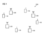
Fig. 1 depicts aradio communications system 1000, wherein the inventive technique is applicable. -
Fig. 2 , illustrates a flow chart depicting the steps performed by the inventive technique. -
Fig. 3 depicts in block diagram form an arrangement of means for executing the inventive technique. - Fig. 4 depicts a section of a cooperative area topology in
radio communications system 1000. - Fig. 5 depicts simulation results for a 2 BSs - 2 MSs case.
- Fig. 6 depicts simulation results for a 3 BSs - 2 MSs case.
- Fig. 7 depicts a performance comparison result between the inventive technique and a conventional technique.
-
Fig. 1 depicts aradio communications system 1000, wherein the inventive technique is applicable.Radio communications system 1000 comprises of a plurality of mobiles stations (MS) 100 and a plurality of base stations 200 (BS). In one embodiment of the inventive technique,BSs 200 co-operate between each other in a COOPA system. A person skilled in the art would be aware that it is also possible to have more than one COOPA systems present in aradio communications system 1000.BSs 200 can be at least one of the following: a base station, an access point, a nodeB, a BSC (base station controller), a RNC (radio network controller). In one embodiment of the inventive technique OFDMA (Orthogonal Frequency Division Multiple Access) techniques are used. -
Fig. 2 , illustrates a flow chart depicting the steps performed by the inventive technique. In step 1 aMS 100, in order to provide feedback to at least one base station of a plurality of base stations measures at least one channel characteristic of a downlink channel. The channel characteristic can be at least one of the following: a channel quality indicator (CQI), a channel power indicator, a signal to interference plus noise power ratio (SINR) measurement. Instep 2 theMS 100 quantises the measured channel characteristic using at least one code selected from a codebook, the codebook comprising of a plurality of codes. A subspace distance metric is used when executing the quantisation. Instep 3, the MS 100 then transmits via a broadcast channel or a control channel, information that relates to the code selected. The information transmitted forming a subset of a group of parameters of the selected code. In one embodiment the subset relates to an index of the selected code in the codebook. - Upon reception of the information from each
MS 100,BSs 200 can then retrieve the code from the codebooks that they have stored and use the code as a weighting factor to perform beam forming. In thisway BSs 200 can ensure that transmissions are received atMSs 100 at a power level that allows the MS 100 to be in the position to decode the transmission without errors. As the information is broadcast or transmitted over a control channel, allBSs 200 that are part of the cooperative antenna system can receive the information and form a clear picture of the radio channel characteristics throughout theradio communications system 1000. Furthermore, in another alternative embodiment, it is also possible for theMS 100 to transmit directly to its servingBS 200 the information and in turn, theBS 200 to then transmit the received information toBSs 200 that are within the COOPA system. The codebook used, is known to bothMSs 100 andBSs 200. It can be predefined by a network operator and provided to all units within theradio communications system 1000. If anMS 100 does not have the codebook it can request it from its servingBS 200. -
Fig. 3 depicts in block diagram form the means that are arranged to execute the inventive technique in aMS 100. ABS 200 also has appropriate means to receive, retrieve and further process the information transmitted fromMS 100. The inventive technique can be implemented, for example, in a ASIC (application specific integrated circuit), a microcomputer. When implementing the inventive technique a programming language, for example C or C++ can be used to programme the necessary software components. -
MS 100 comprises of storage means 110 for storing the codebook. Storage means 110 can be for example a computer memory card. Control means 120 arranged to control theMS 100 as well as, to measure at least one channel characteristic of a downlink channel and to execute the quantisation using a code from the codebook. The control means 120 are arranged to measure at least one of the following: a channel quality indicator, a channel power indicator of a received transmission, a signal to interference plus noise measurement, on a transmission received by transceiver means 130. Control means 120 are further arranged to retrieve codes from storage means 110. Control means 120 are further arranged to provide transceiver means 130 with the appropriate information for transmittal. That is control means 120 are further arranged to select information that is a subset of a group of parameters of the selected code. As mentioned herein above, in one embodiment the subset selected is an index of the selected code in the codebook. - The inventive technique is further explained herein below, wherein the following notation is used:
- Vectors and matrices are denoted by lower case bold and capital bold letters, respectively. (·) T and (·) H denote transpose and Hermitian transpose, respectively. tr(·) denotes the trace of a matrix. || · || and || · ||F denote the two-norm of a vector or a matrix and the Frobenius norm of a matrix, respectively. The covariance matrix of the vector process x is denoted by Rx = E[xx H ], where E[·] is used for expectation. IN is the N x N identity matrix and OM×N stands for an all-zero matrix of size MxN. IMxN is defined as

- [A] i,j stands for the (i,j)th entry of a matrix A. |S| is the size of a set S.
- A precoded MU-MIMO system in which a group of
BSs 200 transmit data tomultiple MSs 100 simultaneously. NBS BSs and NMs MSs have Nt (transmit) and Nr (receive) antennas each, respectively. - The data symbol block, s = [s1, ... , sNtr ] T where
Ntr = NMSNr, is precoded by a Ntt×Ntr matrix W where
Ntt = NBSNt. Here the first Nr data symbols are intended
for the first user orMS 100, the next Nr symbols for the second user orMS 100, and so on. When denoting i BS/i MS as the BS/MS index and i t/i r as the transmit/receive antenna index, respectively, we can denote hij where i = Nr(i MS-1)+i r, j = Nt(i BS-1)+i t as the channel coefficient between the i r th receive antenna of the i MS th MS and the i t th transmit antenna of the iBs th BS. The NtrNtt channel coefficients can be expressed as the NtrxNtt channel matrix H with [H] i,j = hij . The received signals on Ntr receive antennas which are collected in the vector y can be formulated as
where n is the additive white Gaussian noise (AWGN). A transmit zero-forcing filter which completely suppresses
the interference at the receiver, is used:

where P tx is the maximum transmit power. The transmit precoding matrix W which satisfies the design criteria (2) is as follows:

- The challenge here is that
BSs 100 should know the downlink channel matrix H so as to construct the precoding matrix W. The analogue pilot retransmission method has been proposed as a way of transferring channel state information, however the analogue pilot retransmission method is vulnerable to noise enhancement effects and this weakness brings about a significant performance degradation, even though it is efficient in terms of required resources. As a way of combating noise, the digital method can be used instead of the analogue method. The digital method here means thatMSs 100 measure the downlink channel and encode this information into the digital code and send it back to theBSs 200 after performing appropriate digital signal processing (modulation, spreading, repetition, or channel coding, etc) to guarantee robust data transmission. - Thus it is more feasible for each
individual MS 100 to quantize a channel matrix within the scope of itself and send it back to all associatedBSs 200 via a broadcast transmission over a broadcast channel or a control channel. TheBSs 200 can then calculate the precoding matrix by making use of channel information reconstructed by the collected feedback messages. - There are several ways of quantizing channel matrix. A straightforward way is to view the channel matrix as a set of complex numbers, and to encode every complex number individually.
- If we allocate N b bits for representing one floating point number, we need 2N b N MS N r N BS N t bits in total for every subcarrier. This however imposes a high cost on the overhead required. The alternative is to view the channel matrix as a set of complex matrices, and to quantize individual matrix by looking up a predefined codebook. As mentioned above, the overall channel matrix is N MS N r × N BS N t matrix, and is composed of the channel matrix for each user or
MS 100, which is N r x N BS N t matrix. - Equation (4) depicts this relationship. Here H j is the transpose of the channel matrix for user j, which is N BS N t x Nr matrix.
- If we allocate N cb bits for the codebook, we need N cb N MS bits in total for every subcarrier.

- The channel quantization method is suitable for the limited feedback in terms of required feedback bits, and the conventional vector quantization (VQ) method can also be applied.
- As mentioned herein above,
MS j 100 is supposed to quantize its channel matrix H j. H j not viewed just as a complex matrix but as a subspace which is spanned by it. A singular value decomposition (SVD) is executed to extract the unitary matrix U j which includes the basis vectors U j,s spanning the column space of:


- The channel quantizer uses the chordal distance (also known as the subspace distance metric) as a distance metric, since the distance between subspaces is measured. There are other subspace distance metrics, but the chordal distance is the only one which makes the VQ algorithm feasible for designing the codebook. The chordal distance is defined as:


where C i is an unitary matrix

where
- Here, C is the codebook of size N (N = 2Ncb ) which has the code C i ∈ CNtt×Nr .
- Σj,S ∈ RNrxNr is composed of upper Nr x Nr elements of Σ j · Σj,s is a diagonal matrix which has Nr positive real elements in its diagonal. This constitutes the channel power information. The subspace based channel quantization method works as follows. MS 100 j finds the code C i which provides the minimum chordal distance or subspace distance metric with U j,s, and corresponding power information such as channel power information. Then it sends back N cb bit codebook index together with Nr power information to all associated
BSs 200. The reconstructed downlink channel matrix atBSs 200 is as follows.
- The code index alone is enough to achieve potential performances without extra channel power information when link strengths (large-scale fading due to path loss and shadowing) are given to
BSs 200. In this case,
MS 100 needs to send only N cb bit feedback. The channel quantization formula is expressed as:
- The Linde, Buzo, and Gray (LBG) vector quantization (VQ) algorithm is used to construct the codebook C. The LBG VQ algorithm is an iterative algorithm based on the Lloyd algorithm which is known to provide an alternative systematic approach for the subspace packing problem. The codebook is acquired through iteration. The main difference of the proposed method is attributed to the fact that codebooks are not precoder codebooks, but are constructed channel quantizer codebooks.
- The LBG VQ algorithm is based on a training sequence which is provided by channel realizations simulated in Monte-Carlo approach, whereas the Lloyd algorithm is based on an initial codebook which is obtained via random computer search or the currently best codebook. Thus, codebooks obtained by the LBG VQ algorithm can better capture statistics of the channel by using channel realizations as a training sequence.
- The LBG VQ based codebook C design is as follows. Given a source vector with its statistical properties known, given a distortion measure, given a codebook evaluation measure, and given the size of the codebook, a codebook and a partition which result in maximizing the minimum chordal distance of the codebook is required.
- For a training sequence T of which the element is the column space basis vectors U j,s of size N tt xN r :

where X m E C Ntt×Nr is a sample of U j,s which can be obtained by taking SVD of the channel matrix H j . The channel matrix samples are generated by Monte-Carlo simulation which follows SCMe. The number of channel samples M is assumed to be large (e.g., M ≥ 1000N), so that all the statistical properties of the source are captured by the training sequence. The codebook can be represented as the following:
- Each code has the same size as a training vector (Cn ∈ CNttxNr). Let R n be the encoding region associated with code C n and let


- The aim is to find a codebook of which the minimum chordal distance is maximized. The minimum chordal distance of the codebook is given by:

- The codebook design problem can be stated as follows: Given T and N, find C and P such that dc,min (C) is maximised.
- C and P must satisfy the following two criteria so as to solve the above mentioned design problem. It should be noted that the chordal distance is used instead of the Euclidean distance as a distance metric.
-

- This condition says that any channel sample X, which is closer to the code Cn than any other codes in the chordal distance sense, should be assigned to the encoding region Rn, and be represented by C n .
-

where UR is an eigenvector matrix of the sample covariance matrix R which is defined as:

- This condition means that the code C n of the encoding region Rn should be the N r eigenvectors of the sample covariance matrix R corresponding to the N r largest eigenvalues. The centroid condition is designed to minimise the average distortion in the encoding region R n , whenrepresents R n .

- This process is reproduced here for convenience.

- Equation (18) is the optimum solution which minimises the average distortion.
- The modified LBG VQ (mLBG VQ) design algorithm is an iterative algorithm which finds the solution satisfying the two optimality criteria mentioned herein above. The algorithm requires an initial codebook C (0). C (0) is obtained by the splitting of an initial code, which is the centroid of the entire training sequence, into two codes. The iterative algorithm runs with these two codes as the initial codebook.
- The final two codes are split into four and the same process is repeated until the desired number of codes is obtained. The codebook design steps are as follows for given T and ε > 0. "centroid(S)" denotes the optimum code calculated for a given encoding region S.
- Let N = 1 and calculate

- For i = 1, 2,...,N set


- Set the iteration index k = 0 and calculate

- (a) Find


- (b) Update the codes by finding the centroid

- (c) set k = k + 1
- (d) Calculate


- (e) Set

- Repeat steps 2 and 3 until the desired number of codes is obtained.
- The minimum distances of the codebooks are collected in Table 1. It shows that the codebooks acquired by the modified LBG VQ algorithm have better distance properties than Grassmannian codebooks.
- Simulations have been performed for the 2 BSs 200 - 2
MSs MSs 100 cases. Two (three)BSs 200 are cooperating to transmit data signal for twoMSs 100 through the same resources at the same time. BothBSs 200 andMSs 100 have a single antenna, so it yields 2 x 2 and 2 x 3 overall channel matrices, respectively. - SCMe is used for simulations and proposed methods are tested for the Urban Macro channel with mobile speed 10 m/s. The system performance is evaluated in terms of the received SINR (signal to interference plus noise) at the
MS 100. Simulations are performed for 30000 channel realisations and the cumulative distribution function (cdf) at oneMS 100 is obtained. OFDMA is assumed for data transmission scheme and the simulations focus on one subcarrier. - The transmit power at the
BS 200 is set to be 10W and it is equally allocated to 1201 subcarriers. A section of a cooperative area (CA) topology inradio communications system 1000 is shown in Fig. 4. As in the conventional radio communications topology, one cell is composed of three sectors and the hexagonal area, which is composed of three sectors which are served by threeBSs 200, forms a CA. TwoMSs 100 in the CA are served by threeBSs 200 simultaneously. In case of the 2 BSs - 2 MSs case, twoBSs 200 which maintain the strongest two links withMSs 100 are chosen for downlink transmission. - The cell radius is 600 m and
MSs 100 are equally distributed in the CA. The transmit zero-forcing filter formula follows (3), based on downlink channel information which are either perfect channel (pCh), or provided by downlink channel estimation method which are shared by BSs through prompt and error free backbone network (centralized CA, cCA), or acquired by the analogue pilot retransmission method (distributed CA, dCA), or captured and reconstructed by looking up n bit codebook (n bit channel quantization, nbCQ).BSs 200 are assumed to be aware of large-scale fading of the channel, and the channel quantization process (12) is based on true channel information. The codebooks are acquired by the modified LBG VQ algorithm. The feedback link is error free and delay free. - Fig. 5 shows the cdf of SINR for the 2 BSs - 2 MSs case. At 50% cdf, the 3 bit channel quantizer (3bCQ) shows 5.3dB gain over the analogue pilot retransmission case (dCA) and it is only 0.7dB away from the centralized CA (The channel matrix at MS 100 H j (j = 1, 2) is in this case a 2 x 1 complex vector and this is represented by a codebook of
size 23 = 8. - Compared with the channel quantization method, the resource efficient dCA case requires 3 pilot tones per
MS 100 for FDD. Therefore, the proposed scheme outperforms the pilot retransmission method without requiring extra resource. - Fig. 6 deals with simulation results of the 3 BSs - 2 MSs case. 3bCQ, 4bCQ, and 5bCQ cases have 3.2dB, 5.0dB, and 6.1dB gains over dCA case, respectively. The proposed method is to quantize the channel matrix based on the chordal distance and the LBG VQ algorithm is modified as such. Conventional VQ methods use the Euclidean distance instead. A performance comparison result, between the subspace method and the conventional method using an Euclidean distance is shown in Fig.7. The Euclidean distance based CQ (nbeCQ) adopts the Euclidean distance as a distance metric for channel quantization. Its optimality criteria for codebook construction are as follows:
-

-

- The simulation result shows that subspace based CQ has substantial gain over Euclidean distance based CQ. At 50% cdf, 4bCQ and 5bCQ outperform 4beCQ and 5beCQ by 2.9 dB and 2.6 dB, respectively.
- Although the invention has been described in terms of preferred embodiments and refinements described herein, those skilled in the art will appreciate other embodiments and modifications which can be made without departing from the scope of the teachings of the invention. All such modifications are intended to be included within the scope of the claims appended hereto.
Claims (8)
- Method for providing feedback in a radio communications system (1000) between at least one mobile station (100) of a plurality of mobile stations and at least one base station (200) of a plurality of base stations, comprising the steps of:- measuring by said at least one mobile station (100), of at least one channel characteristic of a downlink channel;- quantising by said at least one mobile station (100), said at least one channel characteristic using at least one code selected from a codebook, said codebook comprising a plurality of codes, and- transmitting by said at least one mobile station (100), of information relating to said at least one selected code, said information being a subset of a group of parameters of said at least one selected code.
- Method according to claim 1, wherein said subset is an index of said at least one selected code in said codebook.
- Method according to any of one of the preceding claims, wherein said codebook satisfies a set of criteria.
- Method according to claim 1, wherein said quantisation uses a subspace distance metric.
- Method according to claim 1, wherein said at least one channel characteristic is at least one of the following: a channel quality indicator, a channel power indicator, a signal to interference plus noise power ratio measurement.
- Mobile station (100) adapted for providing feedback in a radio communications system (1000) comprising means arranged to execute the steps of method claims 1 to 5.
- Radio communications system (1000) comprising at least one mobile station according to claim 6.
- Radio communications system (1000) according to claim 7, wherein said radio communications system (1000) comprises of at least one cooperative antenna system.
Priority Applications (1)
| Application Number | Priority Date | Filing Date | Title |
|---|---|---|---|
| EP07003817A EP1962539A1 (en) | 2007-02-23 | 2007-02-23 | Method for providing channel information in a radio communications system and mobile station thereof |
Applications Claiming Priority (1)
| Application Number | Priority Date | Filing Date | Title |
|---|---|---|---|
| EP07003817A EP1962539A1 (en) | 2007-02-23 | 2007-02-23 | Method for providing channel information in a radio communications system and mobile station thereof |
Publications (1)
| Publication Number | Publication Date |
|---|---|
| EP1962539A1 true EP1962539A1 (en) | 2008-08-27 |
Family
ID=38255142
Family Applications (1)
| Application Number | Title | Priority Date | Filing Date |
|---|---|---|---|
| EP07003817A Withdrawn EP1962539A1 (en) | 2007-02-23 | 2007-02-23 | Method for providing channel information in a radio communications system and mobile station thereof |
Country Status (1)
| Country | Link |
|---|---|
| EP (1) | EP1962539A1 (en) |
Cited By (3)
| Publication number | Priority date | Publication date | Assignee | Title |
|---|---|---|---|---|
| EP2203015A1 (en) * | 2008-12-23 | 2010-06-30 | Nokia Siemens Networks OY | Method for generating cooperation areas in communications networks and corresponding network nodes |
| WO2011068295A1 (en) * | 2009-12-02 | 2011-06-09 | Samsung Electronics Co., Ltd. | Hierarchical-cell communication system using asymmetric feedback scheme based on class of access network |
| JP2012249280A (en) * | 2011-04-14 | 2012-12-13 | Fujitsu Ltd | Data processing system and data processing method |
Citations (3)
| Publication number | Priority date | Publication date | Assignee | Title |
|---|---|---|---|---|
| US20060155533A1 (en) * | 2005-01-13 | 2006-07-13 | Lin Xintian E | Codebook generation system and associated methods |
| US20060270360A1 (en) * | 2005-05-30 | 2006-11-30 | Samsung Electronics Co., Ltd. | Apparatus and method for transmitting/receiving data in a mobile communication system using multiple antennas |
| US20070041429A1 (en) * | 2005-08-22 | 2007-02-22 | Aamod Khandekar | Reverse link power control for an OFDMA system |
-
2007
- 2007-02-23 EP EP07003817A patent/EP1962539A1/en not_active Withdrawn
Patent Citations (3)
| Publication number | Priority date | Publication date | Assignee | Title |
|---|---|---|---|---|
| US20060155533A1 (en) * | 2005-01-13 | 2006-07-13 | Lin Xintian E | Codebook generation system and associated methods |
| US20060270360A1 (en) * | 2005-05-30 | 2006-11-30 | Samsung Electronics Co., Ltd. | Apparatus and method for transmitting/receiving data in a mobile communication system using multiple antennas |
| US20070041429A1 (en) * | 2005-08-22 | 2007-02-22 | Aamod Khandekar | Reverse link power control for an OFDMA system |
Cited By (7)
| Publication number | Priority date | Publication date | Assignee | Title |
|---|---|---|---|---|
| EP2203015A1 (en) * | 2008-12-23 | 2010-06-30 | Nokia Siemens Networks OY | Method for generating cooperation areas in communications networks and corresponding network nodes |
| WO2010072565A1 (en) * | 2008-12-23 | 2010-07-01 | Nokia Siemens Networks Oy | Method for generating cooperation areas in communications networks and corresponding network nodes |
| US8781402B2 (en) | 2008-12-23 | 2014-07-15 | Nokia Siemens Networks Oy | Method for generating cooperation areas in communications networks and corresponding network nodes |
| WO2011068295A1 (en) * | 2009-12-02 | 2011-06-09 | Samsung Electronics Co., Ltd. | Hierarchical-cell communication system using asymmetric feedback scheme based on class of access network |
| US8400904B2 (en) | 2009-12-02 | 2013-03-19 | Samsung Electronics Co., Ltd. | Hierarchical-cell communication system using asymmetric feedback scheme based on class of access network |
| JP2013513279A (en) * | 2009-12-02 | 2013-04-18 | サムスン エレクトロニクス カンパニー リミテッド | Operation method of target terminal and small base station, and computer-readable recording medium |
| JP2012249280A (en) * | 2011-04-14 | 2012-12-13 | Fujitsu Ltd | Data processing system and data processing method |
Similar Documents
| Publication | Publication Date | Title |
|---|---|---|
| KR101507088B1 (en) | Aparatus and method for uplink baemforming and space-division multiple access in multi-input multi-output wireless communication systems | |
| US9071301B2 (en) | Precoding with a codebook for a wireless system | |
| EP2189028B1 (en) | System and method for multi-stage zero forcing beamforming in a wireless communications system | |
| US8761288B2 (en) | Limited channel information feedback error-free channel vector quantization scheme for precoding MU-MIMO | |
| KR101719855B1 (en) | Power control method for interference alignment in wireless network | |
| US8995497B2 (en) | Method for operating a secondary station | |
| JP5666581B2 (en) | Precoding method for transmitter of MU-MIMO communication system | |
| WO2020088489A1 (en) | Channel Prediction for Adaptive Channel State Information (CSI) Feedback Overhead Reduction | |
| US11190240B2 (en) | Method and apparatus for sending and receiving channel state information in multiple-input multiple-output network wireless communication systems | |
| US9008008B2 (en) | Method for communicating in a MIMO context | |
| US9319115B2 (en) | Method for providing precoding information in a multi-user MIMO system | |
| US9184817B2 (en) | Method of generating codebook of uniform circular array and acquiring codeword from the codebook | |
| US9635572B2 (en) | Method for coordinating interference in an uplink interference channel for a terminal in a wireless communication system | |
| EP1962539A1 (en) | Method for providing channel information in a radio communications system and mobile station thereof | |
| Maryopi et al. | Sum-rate maximization in uplink CRAN with a massive MIMO fronthaul | |
| Chen et al. | Limited feedback scheme based on zero-forcing precoding for multiuser MIMO-OFDM downlink systems | |
| Tamate et al. | Precoder Design Algorithm using Spatial Signal Synthesis with Multiple Antenna Subset Selection for Hybrid MIMO System | |
| Achoura et al. | User scheduling for beam forming MU–MISO-OFDM Systems |
Legal Events
| Date | Code | Title | Description |
|---|---|---|---|
| PUAI | Public reference made under article 153(3) epc to a published international application that has entered the european phase |
Free format text: ORIGINAL CODE: 0009012 |
|
| AK | Designated contracting states |
Kind code of ref document: A1 Designated state(s): AT BE BG CH CY CZ DE DK EE ES FI FR GB GR HU IE IS IT LI LT LU LV MC NL PL PT RO SE SI SK TR |
|
| AX | Request for extension of the european patent |
Extension state: AL BA HR MK RS |
|
| AKX | Designation fees paid | ||
| STAA | Information on the status of an ep patent application or granted ep patent |
Free format text: STATUS: THE APPLICATION IS DEEMED TO BE WITHDRAWN |
|
| 18D | Application deemed to be withdrawn |
Effective date: 20090228 |
|
| REG | Reference to a national code |
Ref country code: DE Ref legal event code: 8566 |