EP1961897A1 - Locking cylinder - Google Patents
Locking cylinder Download PDFInfo
- Publication number
- EP1961897A1 EP1961897A1 EP07003856A EP07003856A EP1961897A1 EP 1961897 A1 EP1961897 A1 EP 1961897A1 EP 07003856 A EP07003856 A EP 07003856A EP 07003856 A EP07003856 A EP 07003856A EP 1961897 A1 EP1961897 A1 EP 1961897A1
- Authority
- EP
- European Patent Office
- Prior art keywords
- driver
- ring
- locking
- locking cylinder
- cylinder according
- Prior art date
- Legal status (The legal status is an assumption and is not a legal conclusion. Google has not performed a legal analysis and makes no representation as to the accuracy of the status listed.)
- Withdrawn
Links
Images


Classifications
-
- E—FIXED CONSTRUCTIONS
- E05—LOCKS; KEYS; WINDOW OR DOOR FITTINGS; SAFES
- E05B—LOCKS; ACCESSORIES THEREFOR; HANDCUFFS
- E05B47/00—Operating or controlling locks or other fastening devices by electric or magnetic means
- E05B47/06—Controlling mechanically-operated bolts by electro-magnetically-operated detents
- E05B47/0611—Cylinder locks with electromagnetic control
- E05B47/0619—Cylinder locks with electromagnetic control by blocking the rotor
- E05B47/0626—Cylinder locks with electromagnetic control by blocking the rotor radially
- E05B47/0634—Cylinder locks with electromagnetic control by blocking the rotor radially with a pivotally moveable blocking element
-
- E—FIXED CONSTRUCTIONS
- E05—LOCKS; KEYS; WINDOW OR DOOR FITTINGS; SAFES
- E05B—LOCKS; ACCESSORIES THEREFOR; HANDCUFFS
- E05B47/00—Operating or controlling locks or other fastening devices by electric or magnetic means
- E05B47/06—Controlling mechanically-operated bolts by electro-magnetically-operated detents
- E05B47/0676—Controlling mechanically-operated bolts by electro-magnetically-operated detents by disconnecting the handle
- E05B47/0684—Controlling mechanically-operated bolts by electro-magnetically-operated detents by disconnecting the handle radially
- E05B47/0688—Controlling mechanically-operated bolts by electro-magnetically-operated detents by disconnecting the handle radially with a pivotally moveable coupling element
-
- E—FIXED CONSTRUCTIONS
- E05—LOCKS; KEYS; WINDOW OR DOOR FITTINGS; SAFES
- E05B—LOCKS; ACCESSORIES THEREFOR; HANDCUFFS
- E05B47/00—Operating or controlling locks or other fastening devices by electric or magnetic means
- E05B47/06—Controlling mechanically-operated bolts by electro-magnetically-operated detents
- E05B47/0676—Controlling mechanically-operated bolts by electro-magnetically-operated detents by disconnecting the handle
- E05B47/0684—Controlling mechanically-operated bolts by electro-magnetically-operated detents by disconnecting the handle radially
- E05B47/0692—Controlling mechanically-operated bolts by electro-magnetically-operated detents by disconnecting the handle radially with a rectilinearly moveable coupling element
-
- E—FIXED CONSTRUCTIONS
- E05—LOCKS; KEYS; WINDOW OR DOOR FITTINGS; SAFES
- E05B—LOCKS; ACCESSORIES THEREFOR; HANDCUFFS
- E05B15/00—Other details of locks; Parts for engagement by bolts of fastening devices
- E05B15/04—Spring arrangements in locks
- E05B2015/0448—Units of springs; Two or more springs working together
-
- E—FIXED CONSTRUCTIONS
- E05—LOCKS; KEYS; WINDOW OR DOOR FITTINGS; SAFES
- E05B—LOCKS; ACCESSORIES THEREFOR; HANDCUFFS
- E05B15/00—Other details of locks; Parts for engagement by bolts of fastening devices
- E05B15/04—Spring arrangements in locks
- E05B2015/0458—Leaf springs; Non-wound wire springs
Definitions
- the invention concerns a locking cylinder comprising a cylinder housing in which a locking core is pivotably mounted.
- the locking core works together with a locking latch which actuates a lock or a switch and is carried by a ring turnably arranged on said lock core.
- Such a locking cylinder is known from WO 2005/001224 A1 .
- the locking cylinder comprises a ring which is rotatably arranged on the locking core.
- a retention pin is provided which is electric motor driven to-and-fro movable and, in its extended position, engages an opening of the ring. Therewith, a tight connection between locking core and locking latch is generated.
- the retention pin moves radially to the locking core and is directly driven by the electric motor drive. For a secure engagement of the retention pin with the opening, it is necessary that the opening in the ring is in alignment to the retention pin. Otherwise a secure engagement can not be provided.
- the ring comprises on its inner surface at least one recess and preferably a plurality of recesses which are engageable with at least one driver.
- the driver is moveable between a rest position and an engaging position in which the driver connects the ring to the lock core.
- the driver is turnably arranged on a pivot axis extending parallel and excentrical to the pivot axis of the lock core. The driver moves out in the form of a catch and can engage the recess. If a plurality of recesses is provided on the ring an engagement is possible in several rotating positions.
- the force transmission for transmitting the rotating movement is effected essentially along the longitudinal axis of the driver along a chord of the locking core. With that it is possible to transmit high forces. Especially, it is achieved that the driver has only to be moved for little ways in order to effect an engagement. Furthermore, it is possible to move the driver into the engaging position even if the recess is not in alignment with the driver. In the rest position the ring is freely turnable on the locking core.
- the pivot axis of the driver is located in the outer edge portion of the locking core.
- the pivot axis can be arranged in the outer third portion of the locking core.
- the driver is formed as a latch which is retracted in the rest position and, in the engaging position, extends beyond the periphery of the locking core for engaging one of the recesses of the ring. This form of the driver has the effect that relative high forces can be transmitted and that the driver has only to be moved out for a little way for an unobjectionable engagement with the ring.
- the driver is resiliently held in the working position. This has the advantage that an engagement can be effected even if the driver is in a position in which it cannot engage one of the recesses of the ring. It is achieved by the resilient arrangement that the driver is held under prestress in the rest position until the ring and thus the recess reach a position relative to the locking core in which position the driver can move outwardly and engages the recess. Then, the driver engages and the desired torque-proof connection between locking core and ring is provided. A reliable operating of the lock and/or switch is possible.
- the driver is directly moved by an actuator.
- the driver is moved by moving means which are driven from a rest position to a working position by the actuator. In the working position, the moving means move the driver into its engaging position.
- the force transmitting of the torque-proof connection is separated from the movement of the moving means. It is only required to bring the moving means into their working position.
- the moving means engage at least one recess on the inner surface of the ring facing the locking core and that by reason of the rotating movement of the ring with respect to the locking core the driver is moved into engagement with one of the recesses.
- the recesses which can be engaged by the moving means are preferably the same as the recesses in which the driver engages. With that the rotating movement of the locking core is used for the establishment of the torque-proof connection. It is not necessary that the actuator drives correspondingly dimensioned moving means into their working position. It is sufficient to move relative small moving means into the working position whereby the moving means move the driver in the engaging position by reason of the rotating movement of the ring with respect to the locking core. Henceforth, the actuator may be small dimensioned.
- the moving means comprise at least one spring element which is moved between a rest position and a working position by the actuator and directly or indirectly works with the driver.
- the spring element can be designed as a leaf spring being to-and-fro movable in the locking core. With that it is only required to move the leaf spring in its working position by the actuator.
- the actuator may be driven electromechanically or electromagnetically. The further movements especially the moving out of the driver are effected by the rotating movement between ring and locking core.
- the leaf spring with one end engages one recess of the ring and moves a slider by reason of the rotating movement between ring and locking core.
- the slider moves the driver into the engaging position with a recess of the ring.
- the slider is movable along a chord of the locking core and directly or by means of a hinged connection forces the driver into the engaging position. It has been found out that by an appropriate arrangement of the slider, the driver and the leaf spring small ways are sufficient to move the driver into the engaging position.
- the moving means comprise an excentric which moves the driver.
- the excentric is resiliently connected to the driver.
- an excentric can directly be driven by an electric motor.
- two drivers which, depending on the direction of rotation, are moved into their respective engaging positions.
- the arrangement can be such that the drivers are symmetrical to the axis of the locking core. With that it is possible to move the one or the other driver into the engaging position by the slider when the locking core is rotated in the one or the other direction. Especially it is achieved that, depending on the rotating direction, a good power connection from the locking core to the locking latch is provided by the driver. A secure operating of the lock is possible.
- the ring comprises an internal gear with the teeth of which the driver and/or the moving means engage.
- An internal gear comprises a plurality of recesses such that a plurality of engaging positions of the driver between the ring and the locking core exists. An undesired free rotating of the locking core without moving the locking latch is avoided. Further an internal gear can easily be manufactured.
- the schematic shown locking cylinder comprises a locking core 11 which is rotatably arranged in a cylinder housing not shown.
- a ring 12 is rotatably arranged carrying the locking latch 13 for operating a lock or a switch.
- the locking core can be operated by a key or a knob.
- the locking core 11 comprises to drivers 14, 14' which are on a pivot axis 15, 15' pivotably arranged between a rest position and an engaging position.
- drivers 14, 14' which are on a pivot axis 15, 15' pivotably arranged between a rest position and an engaging position.
- the left driver 14 is shown in its engaging position and the right driver 14' is shown in its rest position.
- the pivot axis 15, 15' extend excentrical and parallel to the rotation axis 16 of the locking core 11.
- the driver 14, 14' is formed as a latch through one end of which the pivot axis 15, 15' runs and, in the engaging position, the other end 17 of which can engage with recesses 18 on the inner surface 19 of the ring 12.
- the recesses 18 are formed by an internal gear of the ring 12.
- the left driver 14 engages one of the recesses 18 a torque-proof connection of the locking core 11 to the ring 12 and therewith to the locking latch 13 is generated.
- the lock can be operated by further turning of the locking core.
- the drivers 14, 14' are moved by a slider 20 which is to-and-fro movable along a chord of the locking core 11 within the locking core.
- the slider 20 is shown in its left moved out position whereby the left driver 14 is moved in the engaging position by a lever 21.
- the opposite end of the slider 20 is connected to the right driver 14' by a corresponding lever.
- This driver 14' is moved inwardly in a direction to the turning axis 16 of the locking core after a movement of the slider to the left.
- the right driver 14' comes into the engaging position and the left driver 14 is moved inwardly.
- the slider 20 In the rest position the slider 20 is in a middle position in which both drivers are moved inwardly without extending beyond the periphery of the locking core.
- the slider 20 is moved by a leaf spring 22.
- the arrangement is such that the leaf spring 22 is driven in the direction of arrow 23 within the locking core by an actuator not shown which, for example, can be formed as electromagnetic means or an electromotoric drive or an excentric.
- the leaf spring is guided in the slider and moves radial to the locking core and perpendicular to the slider.
- the slider is movably mounted in the locking core along a chord of the locking core perpendicular to the leaf spring.
- the slider 20 comprises a radial slot through which the leaf spring 22 extends. The slider is movable across and especially perpendicular to the moving direction of the leaf spring 22.
- the free end 24 of the leaf spring can engage with one recess 18 of the ring in the moved-out working position. If the ring 12 is further turned in the direction of arrow 25 with respect to the locking core 11 the leaf spring 22 is moved within the locking core whereby the left driver 14 is pivoted into its engaging position by the lever 21. Then, the end 17 of the driver 14 can engage with another recess 18 of the ring. This allows a transmission of the rotating movement from the locking core to the ring. After finishing the locking operation or after a predetermined time the actuator is released whereby the leaf spring is removed into the locking core such that the slider is moved back in its middle position. Then none of the drivers 14, 14' is moved out and an engagement doesn't take place.
- the drivers 31 are moved between the rest position and the engaging position by means of an excentric 32.
- the driver 31 is formed as a L-like lever the one leg 33 of which engages the internal gear of the ring 12.
- the other leg 34 is connected to the excentric by a spring element 35 such that, by turning of the excentric, the leg 33 is moved out or inwardly, respectively.
- the spring element 35 is designed as a compression-tension spring which is able to transmit both compression forces and tension forces.
- the driver 31 turns around an axis 36 which extends excentrical to the turning axis 16 of the lock core 11 and through the connection region of the legs 33, 34.
- the drivers 14, 14', 31 are resiliently held in the engaging position. With that it is achieved that a secure engagement of the driver with one of the recesses 18 is possible even if one of the drivers is moved out in a position of the ring relative to the locking core in which position an engagement is not possible.
- the driver 14, 14', 31 reaches a position in which it can engage one of the recesses 18.
- the leaf spring is resiliently moved into the working position by the actuator. With that a secure engagement of the leaf spring and one of the recesses 18 on the inner surface of the ring 12 is provided. With that, a secure moving out of the drivers in the engaging position is ensured.
- the internal gear comprises teeth with sharp edges facing the locking core.
- the free end of the leaf spring can be provided with a rounded edge. With that an engagement of the leaf spring in one of the recesses adjacent to the respective tooth of the internal gear is achieved.
- the above-mentioned locking cylinder can be operated with electronic access control units which are well known in the art.
- the invention allows a small power consumption of the driving mechanism for connecting the locking latch to the locking core.
Landscapes
- Physics & Mathematics (AREA)
- Electromagnetism (AREA)
- Mechanical Control Devices (AREA)
Abstract
The invention concerns a locking cylinder comprising a cylinder housing in which a lock core (11) is pivotably mounted. The lock core works together with a locking latch (13) which actuates a lock or a switch and is arranged on a ring (12) turnably mounted on said lock core. According to the invention it is provided that the ring comprises on its inner surface (19) at least one recess (18) and preferably a plurality of recesses which are engageable with at least one driver (14,14'). The driver is moveable between a rest position and an engaging position in which the driver connects the ring to the lock core. The driver is turnably arranged in the lock core on a pivot axis (15,15') extending parallel and excentrical to the pivot axis (16) of the lock core.
Description
- The invention concerns a locking cylinder comprising a cylinder housing in which a locking core is pivotably mounted. The locking core works together with a locking latch which actuates a lock or a switch and is carried by a ring turnably arranged on said lock core.
- Such a locking cylinder is known from
WO 2005/001224 A1 . The locking cylinder comprises a ring which is rotatably arranged on the locking core. A retention pin is provided which is electric motor driven to-and-fro movable and, in its extended position, engages an opening of the ring. Therewith, a tight connection between locking core and locking latch is generated. The retention pin moves radially to the locking core and is directly driven by the electric motor drive. For a secure engagement of the retention pin with the opening, it is necessary that the opening in the ring is in alignment to the retention pin. Otherwise a secure engagement can not be provided. - It is an object of the invention to provide a locking cylinder of the above described kind such that a secure engagement of the retention pin with the pivotable ring is possible. Further it should be provided that an engagement is possible in a plurality of relative positions between the locking core and the ring.
- According to the invention it is provided that the ring comprises on its inner surface at least one recess and preferably a plurality of recesses which are engageable with at least one driver. The driver is moveable between a rest position and an engaging position in which the driver connects the ring to the lock core. In the lock core, the driver is turnably arranged on a pivot axis extending parallel and excentrical to the pivot axis of the lock core. The driver moves out in the form of a catch and can engage the recess. If a plurality of recesses is provided on the ring an engagement is possible in several rotating positions.
- With such an arrangement the force transmission for transmitting the rotating movement is effected essentially along the longitudinal axis of the driver along a chord of the locking core. With that it is possible to transmit high forces. Especially, it is achieved that the driver has only to be moved for little ways in order to effect an engagement. Furthermore, it is possible to move the driver into the engaging position even if the recess is not in alignment with the driver. In the rest position the ring is freely turnable on the locking core.
- Advantageously, the pivot axis of the driver is located in the outer edge portion of the locking core. The pivot axis can be arranged in the outer third portion of the locking core. Further it is advantageous that the driver is formed as a latch which is retracted in the rest position and, in the engaging position, extends beyond the periphery of the locking core for engaging one of the recesses of the ring. This form of the driver has the effect that relative high forces can be transmitted and that the driver has only to be moved out for a little way for an unobjectionable engagement with the ring.
- It can be provided that the driver is resiliently held in the working position. This has the advantage that an engagement can be effected even if the driver is in a position in which it cannot engage one of the recesses of the ring. It is achieved by the resilient arrangement that the driver is held under prestress in the rest position until the ring and thus the recess reach a position relative to the locking core in which position the driver can move outwardly and engages the recess. Then, the driver engages and the desired torque-proof connection between locking core and ring is provided. A reliable operating of the lock and/or switch is possible.
- Generally it is possible that the driver is directly moved by an actuator. According to a preferred embodiment of the invention it is provided that the driver is moved by moving means which are driven from a rest position to a working position by the actuator. In the working position, the moving means move the driver into its engaging position. By such an arrangement the force transmitting of the torque-proof connection is separated from the movement of the moving means. It is only required to bring the moving means into their working position.
- It can be provided that, in its working position, the moving means engage at least one recess on the inner surface of the ring facing the locking core and that by reason of the rotating movement of the ring with respect to the locking core the driver is moved into engagement with one of the recesses. The recesses which can be engaged by the moving means are preferably the same as the recesses in which the driver engages. With that the rotating movement of the locking core is used for the establishment of the torque-proof connection. It is not necessary that the actuator drives correspondingly dimensioned moving means into their working position. It is sufficient to move relative small moving means into the working position whereby the moving means move the driver in the engaging position by reason of the rotating movement of the ring with respect to the locking core. Henceforth, the actuator may be small dimensioned.
- It is useful to hold the moving means in their working position by the force of a spring. This has the advantage that a secure engagement of the moving means with one of the recesses of the ring is provided. In case that the moving means are forced into the working position without being able to engage one of the recesses the moving means are held under pretension by the spring and engage one recess during the further rotation of the ring with respect to the locking core. Then the moving means can move the driver in the engaging position and the lock can be operated.
- According to an embodiment of the invention it is provided that the moving means comprise at least one spring element which is moved between a rest position and a working position by the actuator and directly or indirectly works with the driver. For example, the spring element can be designed as a leaf spring being to-and-fro movable in the locking core. With that it is only required to move the leaf spring in its working position by the actuator. The actuator may be driven electromechanically or electromagnetically. The further movements especially the moving out of the driver are effected by the rotating movement between ring and locking core.
- Furthermore, it can be provided that, in the working position, the leaf spring with one end engages one recess of the ring and moves a slider by reason of the rotating movement between ring and locking core. The slider moves the driver into the engaging position with a recess of the ring. The slider is movable along a chord of the locking core and directly or by means of a hinged connection forces the driver into the engaging position. It has been found out that by an appropriate arrangement of the slider, the driver and the leaf spring small ways are sufficient to move the driver into the engaging position.
- Alternatively, it can be provided that the moving means comprise an excentric which moves the driver. In an preferred embodiment the excentric is resiliently connected to the driver. For example, an excentric can directly be driven by an electric motor.
- According to an embodiment of the invention there are provided two drivers which, depending on the direction of rotation, are moved into their respective engaging positions. The arrangement can be such that the drivers are symmetrical to the axis of the locking core. With that it is possible to move the one or the other driver into the engaging position by the slider when the locking core is rotated in the one or the other direction. Especially it is achieved that, depending on the rotating direction, a good power connection from the locking core to the locking latch is provided by the driver. A secure operating of the lock is possible.
- Further, it can be provided that the ring comprises an internal gear with the teeth of which the driver and/or the moving means engage. An internal gear comprises a plurality of recesses such that a plurality of engaging positions of the driver between the ring and the locking core exists. An undesired free rotating of the locking core without moving the locking latch is avoided. Further an internal gear can easily be manufactured.
- The invention is now described in detail with the accompanying schematic drawing. In the drawing
- Fig. 1
- shows a sectional view of a first embodiment of a locking cylinder according to the invention,
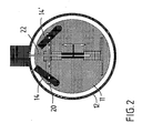
- Fig. 2
- shows a sectional view of a second embodiment of a locking cylinder according to the invention, and
- Fig. 3
- shows a sectional view of a third embodiment of a locking cylinder according to the invention.
- According to
Fig. 1 the schematic shown locking cylinder comprises a lockingcore 11 which is rotatably arranged in a cylinder housing not shown. On the locking core aring 12 is rotatably arranged carrying the lockinglatch 13 for operating a lock or a switch. The locking core can be operated by a key or a knob. - In the region of the
ring 12 the lockingcore 11 comprises todrivers 14, 14' which are on apivot axis 15, 15' pivotably arranged between a rest position and an engaging position. In the drawing theleft driver 14 is shown in its engaging position and the right driver 14' is shown in its rest position. - The
pivot axis 15, 15' extend excentrical and parallel to therotation axis 16 of the lockingcore 11. Thedriver 14, 14' is formed as a latch through one end of which thepivot axis 15, 15' runs and, in the engaging position, theother end 17 of which can engage with recesses 18 on theinner surface 19 of thering 12. In the embodiment shown in the drawing, the recesses 18 are formed by an internal gear of thering 12. - If, in the drawing, the
left driver 14 engages one of the recesses 18 a torque-proof connection of the lockingcore 11 to thering 12 and therewith to the lockinglatch 13 is generated. The lock can be operated by further turning of the locking core. - According to the embodiment in
Fig. 1 thedrivers 14, 14' are moved by aslider 20 which is to-and-fro movable along a chord of the lockingcore 11 within the locking core. InFig. 1 theslider 20 is shown in its left moved out position whereby theleft driver 14 is moved in the engaging position by alever 21. The opposite end of theslider 20 is connected to the right driver 14' by a corresponding lever. This driver 14' is moved inwardly in a direction to the turningaxis 16 of the locking core after a movement of the slider to the left. In the other case, i.e. when theslider 20 is moved to the right, the right driver 14' comes into the engaging position and theleft driver 14 is moved inwardly. In the rest position theslider 20 is in a middle position in which both drivers are moved inwardly without extending beyond the periphery of the locking core. - The
slider 20 is moved by aleaf spring 22. The arrangement is such that theleaf spring 22 is driven in the direction ofarrow 23 within the locking core by an actuator not shown which, for example, can be formed as electromagnetic means or an electromotoric drive or an excentric. The leaf spring is guided in the slider and moves radial to the locking core and perpendicular to the slider. The slider is movably mounted in the locking core along a chord of the locking core perpendicular to the leaf spring. Theslider 20 comprises a radial slot through which theleaf spring 22 extends. The slider is movable across and especially perpendicular to the moving direction of theleaf spring 22. - As shown in the drawing, the
free end 24 of the leaf spring can engage with one recess 18 of the ring in the moved-out working position. If thering 12 is further turned in the direction ofarrow 25 with respect to the lockingcore 11 theleaf spring 22 is moved within the locking core whereby theleft driver 14 is pivoted into its engaging position by thelever 21. Then, theend 17 of thedriver 14 can engage with another recess 18 of the ring. This allows a transmission of the rotating movement from the locking core to the ring. After finishing the locking operation or after a predetermined time the actuator is released whereby the leaf spring is removed into the locking core such that the slider is moved back in its middle position. Then none of thedrivers 14, 14' is moved out and an engagement doesn't take place. - With such an arrangement a power transmission between locking
core 11 andring 12 is provided by the means of one of thedrivers 14, 14' which is moved out into the engaging position without the help of an actuator but only with the help of the rotating movement between the locking core and the ring. Henceforth, for initializing the locking operation, it is only required to move the leaf spring in its working position in which thefree end 24 of the leaf spring engages one recess 18 of the ring. - This can be provided by a small dimensioned actuator. This has the advantage of little power consumption.
- In the embodiment of a locking cylinder according to
Fig. 2 theslider 20 works directly with thedriver 14. With that a space-saving construction is possible. The further functions are the same to those of the locking cylinder according toFig. 1 and the same or the same working elements have the same reference numbers. - In the embodiment according to
Fig. 3 thedrivers 31 are moved between the rest position and the engaging position by means of an excentric 32. Thedriver 31 is formed as a L-like lever the oneleg 33 of which engages the internal gear of thering 12. Theother leg 34 is connected to the excentric by aspring element 35 such that, by turning of the excentric, theleg 33 is moved out or inwardly, respectively. Thespring element 35 is designed as a compression-tension spring which is able to transmit both compression forces and tension forces. Thedriver 31 turns around anaxis 36 which extends excentrical to the turningaxis 16 of thelock core 11 and through the connection region of thelegs - All embodiments have in common that the
drivers core 11 with respect to thering 12 thedriver leaf spring 22 or of thespring elements 35 theslider 20 or the L-like driver 31 is moved out and an engagement takes place. In the embodiments ofFig. 1 andFig. 2 it may be further provided that the leaf spring is resiliently moved into the working position by the actuator. With that a secure engagement of the leaf spring and one of the recesses 18 on the inner surface of thering 12 is provided. With that, a secure moving out of the drivers in the engaging position is ensured. - It can be provided that the internal gear comprises teeth with sharp edges facing the locking core. The free end of the leaf spring can be provided with a rounded edge. With that an engagement of the leaf spring in one of the recesses adjacent to the respective tooth of the internal gear is achieved.
- By such an arrangement of the driver it is further possible to remove the actuator in its rest position even during the locking operating. By reason of the compression force acting on the driver the latter is held in its engaging position even if the actuator is removed. After releasing the compression force acting on the driver the driver is turned back in its rest position by the force of the spring. Further, great forces can be transmitted because the direction of forces to be transmitted runs along the longitudinal extension of the driver.
- The above-mentioned locking cylinder can be operated with electronic access control units which are well known in the art. The invention allows a small power consumption of the driving mechanism for connecting the locking latch to the locking core.
Claims (14)
- Locking cylinder comprising a cylinder housing in which a lock core (11) is pivotably mounted and works together with a locking latch (13) which actuates a lock or a switch and is arranged on a ring (12) turnably mounted on said lock core, characterized in that the ring comprises on its inner surface (19) facing the locking core at least one recess (18) and preferably a plurality of recesses which are engageable with at least one driver (14, 14', 31) which is moveable between a rest position and an engaging position in which the driver connects the ring with the lock core and which driver is turnably arranged in the lock core on a pivot axis (15, 15' 36) extending parallel and excentrical to the pivot axis (16) of the lock core.
- Locking cylinder according to claim 1, characterized in that the pivot axis (15, 15' 36) is located in the outer edge region of the locking core (11).
- Locking cylinder according to claim 1 or 2, characterized in that the driver (14, 14', 31) is formed as a lever which is retracted in the rest position and, in the working position, extends beyond the periphery of the locking core for engaging one of the recesses of the ring.
- Locking cylinder according to one of the claims 1 to 3, characterized in that the driver (14, 14', 31) is resiliently held in its engaging position.
- Locking cylinder according to one of the claims 1 to 4, characterized in that the driver (14, 14', 31) is moved by moving means (20, 22, 32) which are moved between a rest position and a working position by an actuator in which working position the moving means drives the driver into its engaging position.
- Locking cylinder according to claim 5, characterized in that, in the working position, the moving means (22) engage at least one recess (18) on the inner surface of the ring (12) and drives the driver into engagement with one of the recesses by reason of the rotating movement between the ring and the locking core.
- Locking cylinder according to one of the claims 5 or 6, characterized in that the moving means is resiliently held in its working position.
- Locking cylinder according to one of the claims 5 to 7, characterized in that the moving means comprise at least one spring means (22) which are movable between a rest position and a working position by an actuator and directly or indirectly work together with the driver.
- Locking cylinder according to claim 8, characterized in that the spring means (22) are formed as a leaf spring which is to-and-fro movable in the locking core.
- Locking cylinder according to one of the claims 8 or 9, characterized in that, in the working position, one end (24) of the leaf spring (22) engages a recess (18) of the ring (12) whereby the leaf spring is moved out and moves a slider by reason of the rotating movement between the ring and the locking core which slider moves the driver (14, 14') in its engaging position with one of the recesses (18) of the ring.
- Locking cylinder according to one of the claims 1 to 6, characterized in that the moving means comprise an excentric (32) which moves the driver (31).
- Locking cylinder according to claim 11, characterized in that the excentric is resiliently connected to the driver.
- Locking cylinder according to one of the claims 1 to 12, characterized in that two drivers (14, 14', 31) are provided which are moved in their respective engaging position depending on the rotation direction.
- Locking cylinder according to one of the claims 1 to 13, characterized in that the ring (12) comprise an internal gear with the teeth of which the driver and/or the moving means engage.
Priority Applications (1)
| Application Number | Priority Date | Filing Date | Title |
|---|---|---|---|
| EP07003856A EP1961897A1 (en) | 2007-02-26 | 2007-02-26 | Locking cylinder |
Applications Claiming Priority (1)
| Application Number | Priority Date | Filing Date | Title |
|---|---|---|---|
| EP07003856A EP1961897A1 (en) | 2007-02-26 | 2007-02-26 | Locking cylinder |
Publications (1)
| Publication Number | Publication Date |
|---|---|
| EP1961897A1 true EP1961897A1 (en) | 2008-08-27 |
Family
ID=38214999
Family Applications (1)
| Application Number | Title | Priority Date | Filing Date |
|---|---|---|---|
| EP07003856A Withdrawn EP1961897A1 (en) | 2007-02-26 | 2007-02-26 | Locking cylinder |
Country Status (1)
| Country | Link |
|---|---|
| EP (1) | EP1961897A1 (en) |
Citations (6)
| Publication number | Priority date | Publication date | Assignee | Title |
|---|---|---|---|---|
| WO1991012400A1 (en) * | 1990-02-14 | 1991-08-22 | Bewator Ab | Clutch mechanism |
| EP0995864A2 (en) * | 1998-10-20 | 2000-04-26 | Günter Uhlmann | Electro-mechanical lock system |
| WO2003100199A1 (en) * | 2002-05-27 | 2003-12-04 | Mul-T-Lock Technologies Ltd. | Lock |
| DE10324690A1 (en) * | 2002-06-10 | 2004-02-05 | Mehmet Sancak | Method for remotely operating a cylinder lock has two separable sections which may be locked together electrically or by means of a key |
| WO2005001224A1 (en) * | 2003-06-23 | 2005-01-06 | Buga Technologies Gmbh | Electromechanical lock cylinder |
| WO2005093191A1 (en) * | 2004-03-26 | 2005-10-06 | Pbt (Ip) Limited | Radial clutch with piezo ceramic operation |
-
2007
- 2007-02-26 EP EP07003856A patent/EP1961897A1/en not_active Withdrawn
Patent Citations (6)
| Publication number | Priority date | Publication date | Assignee | Title |
|---|---|---|---|---|
| WO1991012400A1 (en) * | 1990-02-14 | 1991-08-22 | Bewator Ab | Clutch mechanism |
| EP0995864A2 (en) * | 1998-10-20 | 2000-04-26 | Günter Uhlmann | Electro-mechanical lock system |
| WO2003100199A1 (en) * | 2002-05-27 | 2003-12-04 | Mul-T-Lock Technologies Ltd. | Lock |
| DE10324690A1 (en) * | 2002-06-10 | 2004-02-05 | Mehmet Sancak | Method for remotely operating a cylinder lock has two separable sections which may be locked together electrically or by means of a key |
| WO2005001224A1 (en) * | 2003-06-23 | 2005-01-06 | Buga Technologies Gmbh | Electromechanical lock cylinder |
| WO2005093191A1 (en) * | 2004-03-26 | 2005-10-06 | Pbt (Ip) Limited | Radial clutch with piezo ceramic operation |
Similar Documents
| Publication | Publication Date | Title |
|---|---|---|
| US6174005B1 (en) | Bi-directional handle and latch assembly | |
| US9464463B2 (en) | Combination lock | |
| EP2028334A2 (en) | Door Lock Apparatus for vehicle | |
| RU2007139009A (en) | SIDE DOOR VEHICLE | |
| CN106869612B (en) | Clutch transmission device applied to electronic lock | |
| CN107002433B (en) | Car door movement device | |
| US10563434B2 (en) | Locking unit for a motor vehicle | |
| DE102007013228B4 (en) | Steering wheel lock device | |
| KR20180005888A (en) | Door locking device | |
| EP2163715B1 (en) | Motor-driven lock with a rotary bolt | |
| KR20090120132A (en) | A clutch module for digital door lock | |
| CN108678563B (en) | Door lock | |
| JP2012180739A (en) | Closing device | |
| EP1961897A1 (en) | Locking cylinder | |
| CA2928792C (en) | Combination lock | |
| CN101025062B (en) | Safety lock | |
| JP6277509B2 (en) | Electronic lock | |
| CN101571014B (en) | Unlocking control mechanism | |
| US20210102412A1 (en) | Vehicle door lock device | |
| JP6007129B2 (en) | Door lock device | |
| CN203905663U (en) | Combined lock | |
| CN105644497B (en) | Lenkradschlossvorrichtung | |
| EP2385198B1 (en) | Electromechanical lock adapted to doors | |
| CN101769098B (en) | Clutch mechanism for indoor manual open-type anti-theft lock | |
| EP1121504B1 (en) | Vehicle door lock actuator |
Legal Events
| Date | Code | Title | Description |
|---|---|---|---|
| PUAI | Public reference made under article 153(3) epc to a published international application that has entered the european phase |
Free format text: ORIGINAL CODE: 0009012 |
|
| AK | Designated contracting states |
Kind code of ref document: A1 Designated state(s): AT BE BG CH CY CZ DE DK EE ES FI FR GB GR HU IE IS IT LI LT LU LV MC NL PL PT RO SE SI SK TR |
|
| AX | Request for extension of the european patent |
Extension state: AL BA HR MK RS |
|
| AKX | Designation fees paid | ||
| REG | Reference to a national code |
Ref country code: DE Ref legal event code: 8566 |
|
| STAA | Information on the status of an ep patent application or granted ep patent |
Free format text: STATUS: THE APPLICATION IS DEEMED TO BE WITHDRAWN |
|
| 18D | Application deemed to be withdrawn |
Effective date: 20090228 |