EP1956552B1 - Visual enhancement of interval changes using a temporal subtraction technique - Google Patents
Visual enhancement of interval changes using a temporal subtraction technique Download PDFInfo
- Publication number
- EP1956552B1 EP1956552B1 EP20070102011 EP07102011A EP1956552B1 EP 1956552 B1 EP1956552 B1 EP 1956552B1 EP 20070102011 EP20070102011 EP 20070102011 EP 07102011 A EP07102011 A EP 07102011A EP 1956552 B1 EP1956552 B1 EP 1956552B1
- Authority
- EP
- European Patent Office
- Prior art keywords
- image
- subtraction
- floating
- reference image
- registration
- Prior art date
- Legal status (The legal status is an assumption and is not a legal conclusion. Google has not performed a legal analysis and makes no representation as to the accuracy of the status listed.)
- Not-in-force
Links
Images


Classifications
-
- G—PHYSICS
- G06—COMPUTING; CALCULATING OR COUNTING
- G06T—IMAGE DATA PROCESSING OR GENERATION, IN GENERAL
- G06T7/00—Image analysis
- G06T7/0002—Inspection of images, e.g. flaw detection
- G06T7/0012—Biomedical image inspection
- G06T7/0014—Biomedical image inspection using an image reference approach
- G06T7/0016—Biomedical image inspection using an image reference approach involving temporal comparison
-
- G—PHYSICS
- G06—COMPUTING; CALCULATING OR COUNTING
- G06T—IMAGE DATA PROCESSING OR GENERATION, IN GENERAL
- G06T7/00—Image analysis
- G06T7/30—Determination of transform parameters for the alignment of images, i.e. image registration
- G06T7/35—Determination of transform parameters for the alignment of images, i.e. image registration using statistical methods
-
- G—PHYSICS
- G06—COMPUTING; CALCULATING OR COUNTING
- G06T—IMAGE DATA PROCESSING OR GENERATION, IN GENERAL
- G06T2207/00—Indexing scheme for image analysis or image enhancement
- G06T2207/30—Subject of image; Context of image processing
- G06T2207/30004—Biomedical image processing
- G06T2207/30061—Lung
Definitions
- the present invention relates to a visual enhancement technique to improve the detection of pathological changes from medical images acquired at different times.
- WO 99/05641 and US 5 982 953 disclose further methods for calculating temporal substraction images based on filtered and registered images.
- the rigid body transformation is a translation
- the present invention discloses a subtraction technique using a convolution filter to avoid a changed pathology to disappear in the subtraction image in the case of an accurate registration.
- the method is validated for temporal CT data sets of the thorax for lung cancer follow-up and compared to the conventional subtraction technique using an automated objective measure,
- the present invention is generally implemented as a computer program product adapted to carry out the method of any of the claims when run on a computer and is stored on a computer readable medium.
- the first image acquired in time is called the original scan F (floating image) and we will refer to the image acquired at a later point in time as the follow-up scan R (reference image).
- the follow-up scan R reference image
- MI mutual information
- the only transformation applied to the floating image is a translation.
- the translation depends on the viewpoint q selected by the user, and varies with varying viewpoint. This is accomplished as follows:
- the original and follow-up scans are shown together in three orthogonal views which are updated each time the user clicks a new viewpoint. Both images are shown simultaneously such that the image points that coincide with the viewpoint q are corresponding points according to the deformation field.
- the viewer obeys the conditions stated above.
- Primary by applying a translation to the original scan for each viewpoint, anatomical structures of both scans are shown concurrently.
- a translation is a rigid transformation the size of the pathologies is preserved.
- the temporal subtraction image might become problematic if the registration algorithm allows for large local deformations. This is demonstrated in Fig.2 . Generally, one can state that the subtraction image is misleading when the transformation field changes the size of the pathology locally. Hence, only global deforming registration algorithms are applicable for this technique.
- the clinician who reads the subtraction images must be aware of registration artifacts, which induce a low signal-to-noise ratio. A training phase is needed for the clinician to be able to distinct registration artifacts from true interval change patterns.
- an alternative method is disclosed to compute the subtraction image. It avoids the interval changes to disappear when the pathology in the reference image is matched onto the pathology in the floating image. This is achieved as follows ( Fig.3 ).
- measuring the amount of density I w at each voxel (x,y,z) of an image I is equal to convolving the image with the template H w :
- I w x ⁇ y ⁇ z I x y z ⁇ H w x y z
- expression (4) simplifies to the conventional computed subtraction image (1).
- the technique according to the present invention was tested on temporal CT data sets of the thorax for patient follow-up.
- Four cases, each consisting of two temporal images were involved in this study: two patients contained malignant nodules, one patient had a growing tumor and one case contained metastases. The time between consecutive acquisitions ranged from 39 to 57 days.
- Each scan consisted of 5-mm slices of dimensions 512 ⁇ 512.
- the follow-up scan was registered to the original scan in each of the four cases using the registration algorithm described higher.
- the registration accuracy was expressed by computing the distance between the nodules in the original scan and the nodules in the follow-up scan after alignment. The registration accuracy was 2.0 ⁇ 1.4 millimeter for the first nodule case and 5.8 ⁇ 3.1 for the second patient.
- the subtraction image is intended as a tool for the visual enhancement of pathological changes, but it can also serve as a preprocessing step towards automated detection of interval changes.
- a grown nodule for example, is characterized by a specific pattern in the subtraction image. This enables the automated detection of a grown nodule and offers an opportunity to compare the two subtraction methods quantitatively: if we build a detection system based on one of the two subtraction methods, the outcome of this system to a detection experiment serves as an objective measure for this method.
- the following experiment was performed. First, 14 grown nodules were detected manually in the data sets of the previous experiment. Secondly, the 2D intensity patterns around the nodule locations in the corresponding slices of the subtraction image were used to train a pattern detector.
- An example of a pattern detector may be based on 2D intensity patterns as described in 'Image segmentation using local shape and gray-level appearance models', D. Seghers, D. Loeckx, F. Maes, P. Suetens in Proc. SPIE Conference on Medical Imaging, 2006 .
- the pattern detector may be based on center-Surround filters.
- the detection system is then validated with a leave-one-out approach: one of the nodules is removed from the training set, the detector is trained again on the reduced training set and finally, the detector is asked to find the location of the removed nodule in the corresponding slice of the subtraction image.
- the pattern detector builds a statistical model of profiles consisting of n c points sampled on a circle with radius r c centered around the nodule location.
- the profiles are sampled in 60 LOI feature images.
- Table 1 reports the results of the detection systems using (a) the conventional method and (b) the method introduced in this disclosure. The alternative method seems to perform significantly better that the standard method.
Description
- The present invention relates to a visual enhancement technique to improve the detection of pathological changes from medical images acquired at different times.
- Patient follow-up is a major part of the daily clinical practice of the radiologist. To detect pathological changes as growing nodules, interstitial infiltrates and pleural effusions in the lungs, a current thorax image is compared with a previous recorded image. Temporal subtraction is a popular technique to aid the radiologist with this time consuming task. A previous image is subtracted from the current image after proper alignment and warping to visually enhance the pathological changes. Several studies have shown that a system with temporal subtraction significantly increases the detection rate of interval changes in digital chest radiographs. Studies have also shown that the technique also positively influences the radiologist's interpretation time. A few studies have applied temporal subtraction of CT images for cancer detection. Nowadays, temporal subtraction of chest radiographs has made its entrance in commercially available CAD systems.
- Prior to subtracting one image from the other, alignment of the corresponding anatomical structures is needed to remove irrelevant information from the subtraction image. Computed radiography or computed tomography images of the thorax suffer from non-rigid geometric distortions caused by the 3D displacement of corresponding structures due to differences in patient pose and inhalation, which pleads for the choice of a nonrigid registration algorithm. On the other hand, non-rigid warping has the unwanted effect of changing the size of a lesion. A tumor in a previous image might be blown up to match the tumor in the current image, such that no changes can be observed in the subtraction image. Hence, most authors use a warping technique which does not allow for large local deformations. For example, D. Loeckx et al., "Temporal subtraction, of thorax CR images using a statistical deformation model", IEEE Trans, Med. Imag. 22(11), pp. 1490-1504, 2003 applied a PCA deformation field which was trained on example deformation to capture inhalation and pose difference modes.
-
WO 99/05641 US 5 982 953 disclose further methods for calculating temporal substraction images based on filtered and registered images. - It is an aspect of this invention to provide a viewer application suitable to allow comparison of pathological changes from medical images acquired at different times that overcomes the drawbacks of the prior art.
- A viewer application is disclosed in
US 2001/0002934 . - Other aspects of the present invention will become apparent from the description given below.
- The above aspect are provided by a method of displaying as set out in claim 1.
- In one embodiment the rigid body transformation is a translation.
- In one embodiment three orthogonal views of an image are shown.
- The present invention discloses a subtraction technique using a convolution filter to avoid a changed pathology to disappear in the subtraction image in the case of an accurate registration. The method is validated for temporal CT data sets of the thorax for lung cancer follow-up and compared to the conventional subtraction technique using an automated objective measure,
- The present invention is generally implemented as a computer program product adapted to carry out the method of any of the claims when run on a computer and is stored on a computer readable medium.
-
-
Figure 1 shows the original and follow-up scans together in three orthogonal views which are updated each time the user clicks a new viewpoint. Both images are shown simultaneously such that the image points that coincide with the viewpoint q are corresponding points according to the deformation field. The only transformation applied to the floating image is a translation such that the size of the pathologies is preserved. -
Figure 2 illustrates that the deformation field (c) deforms the simulated reference nodule (b), almost perfectly onto the floating nodule (a). The deformed floating nodule is estimated by interpolating the floating nodule according to the deformation field. The difference image (d) is then computed by subtracting the deformed floating from the reference image. As the registration is perfect, the temporal subtraction does host enhance interval changes.
The intensities range from 0 to 1 for (a) and (b) and from -1 to 1 in (d). -
Figure 3 : Consider the corresponding voxels g(r) and r in the floating (a) and reference (b) image respectively. Instead of subtracting the corresponding intensity values which would yield a zero valued voxel, an alternative approach to compute the subtraction image is applied. In a first step towards this solution, one computes the amount of density available in both images in a region surrounding the corresponding voxels, by integrating the intensities with a template Hw centered at the voxel of interest (c-d). As the simulated nodule has grown, the density amount in the reference image at r will be larger than the amount in the floating image at g(r). -
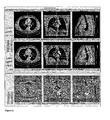
Figure 4 shows the comparison of the conventional method (first row) and the alternative method (second row) for the simulated grown nodule inFig. 2 with several registration errors: (a) perfect registration, (b) Δx1=2,Δy1=2 and Δr 1=0, (c) Δx 1=0,Δy1=0 and Δr 1=3, (d) Δx 1=0,Δy 1=0 and Δr 1=-3 and (e) Δx 1=2,Δy 1=2 and Δr 1=3. The alternative method clearly enhances the interval changes when a perfect registration is applied. This method also seems to be more robust to registration errors than the standard method, as for each case a white spot surrounded by a more or less black region is generated. -
Figure 5 shows the described viewer with three extra views of the subtracted image. The subtraction image immediately attracts the reader's attention to four grown modules. -
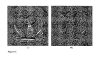
Figure 6 illustrates the comparison of the two subtraction methods. The alternative subtraction image (a) shows a white spot caused by a grown module. The same slice of the subtraction image using the conventional method does not enhance this pathological change (b). - To visually enhance the pathological changes between images of the same patient acquired at different points in time, nonrigid registration is necessary to align both images such that corresponding structures coincide. The first image acquired in time is called the original scan F (floating image) and we will refer to the image acquired at a later point in time as the follow-up scan R (reference image). For the registration, a nonrigid tensor-product B-spline transformation model is adopted, using mutual information (MI) as similarity measure. The resulting transformation that maps every location r R onto a corresponding location r F will be referred to as g(r R ).
- An image viewer (
Fig. 1 ) that accommodates the needs of follow-up applications has been developed.
As the reader of the temporal images is interested in the detection of pathological changes, the viewer needs to display anatomical corresponding structures of both scans simultaneously. This is the case for viewers which show the warped original scan and the follow-up scan together. Unfortunately, such a viewer might conceal pathology changes as the non-rigid warping can have the unwanted effect of changing the size of the pathology. - To compensate for this, a viewer is presented that aligns corresponding structures in both scans while avoiding a nonrigid transformation of the floating image F. Instead, the only transformation applied to the floating image is a translation. The translation depends on the viewpoint q selected by the user, and varies with varying viewpoint. This is accomplished as follows:
- Compute the image point of the reference image r R corresponding to the viewpoint q(x,y,z) .
- Apply the nonrigid deformation field g(r R ) to find the corresponding point r F in the floating image.
- Finally, translate the floating image such that r F coincides with q.
- Thus, the original and follow-up scans are shown together in three orthogonal views which are updated each time the user clicks a new viewpoint. Both images are shown simultaneously such that the image points that coincide with the viewpoint q are corresponding points according to the deformation field. The viewer obeys the conditions stated above. Primary, by applying a translation to the original scan for each viewpoint, anatomical structures of both scans are shown concurrently. Secondly, as a translation is a rigid transformation the size of the pathologies is preserved.
- Once the temporal images are aligned, a subtraction image S is constructed by subtracting the intensities of corresponding voxels:

- Several clinical validation studies have shown the improved detection of interval changes when the temporal subtraction image is offered. On the other hand, one should keep the following issues in mind when implementing and interpreting this technique.
- Firstly, the temporal subtraction image might become problematic if the registration algorithm allows for large local deformations. This is demonstrated in
Fig.2 .
Generally, one can state that the subtraction image is misleading when the transformation field changes the size of the pathology locally. Hence, only global deforming registration algorithms are applicable for this technique.
Secondly, the clinician who reads the subtraction images must be aware of registration artifacts, which induce a low signal-to-noise ratio. A training phase is needed for the clinician to be able to distinct registration artifacts from true interval change patterns. - According to the present invention an alternative method is disclosed to compute the subtraction image.
It avoids the interval changes to disappear when the pathology in the reference image is matched onto the pathology in the floating image. This is achieved as follows (Fig.3 ). - Consider the corresponding voxels g(r) and r in the floating (a) and reference (b) image respectively. Instead of subtracting the corresponding intensity values which would yield a zero valued voxel, an alternative approach is presented. First, the amount of density is computed which is available in both images in a region surrounding the corresponding voxels, by integrating the intensities with a template Hw centered at the voxel of interest. This is shown in
Fig. 3 (c-d). As the simulated nodule has grown, the density amount in the reference image at r will be larger than the amount in the floating image at g(r) . The template Hw with dimensions (w,w,w) has normalized intensities


- In a first experiment, the methods (1) and (4) are compared for the simulated images of
Fig.2 : the floating image (a) contained a nodule at (x 1,y 1)=(40,40) with radius r 1=10, the nodule in the reference image (b) was centered at (x 2' y 2)=(60,60) and had radius r 2=20. Both images had dimensions 100x100. A constant template function Hw =1/w 2 with window size w=11 was chosen. We used a mathematical deformation model to transform the reference nodule (x 2,y 2,r 2) to the nodule (x 1+Δx 1,y 1+Δy 1,r 1+Δr 1). The parameters Δx 1, Δy 1 and Δr 1 were introduced to simulate registration errors.Fig. 4 compares the conventional method (first row) and the alternative method (second row) for several registration errors: (a) perfect registration, (b) Δx 1=2,Δy 1=2,Δr 1=0, (c) Δx 1=0,Δy 1=0,Δr 1=3, (d) Δx 1=0,Δy 1=0,Δr 1=-3 and (e) Δx 1=2,Δy 1=2,Δr 1=3.
The alternative method clearly enhances the interval changes when a perfect registration is applied. This method also seems to be more robust to registration errors than the standard method, as for each case a white spot surrounded by a more or less black region is generated. - The technique according to the present invention was tested on temporal CT data sets of the thorax for patient follow-up. Four cases, each consisting of two temporal images were involved in this study: two patients contained malignant nodules, one patient had a growing tumor and one case contained metastases. The time between consecutive acquisitions ranged from 39 to 57 days. Each scan consisted of 5-mm slices of dimensions 512×512.
The follow-up scan was registered to the original scan in each of the four cases using the registration algorithm described higher. For the two nodule cases, the registration accuracy was expressed by computing the distance between the nodules in the original scan and the nodules in the follow-up scan after alignment. The registration accuracy was 2.0±1.4 millimeter for the first nodule case and 5.8±3.1 for the second patient. Similar registration accuracies were measured for the two other data sets.
The subtraction images were computed using a template function Hw with wx = wy = 11 and wz =3. The viewer described higher extended with three extra views of the subtraction image is shown inFig. 5 . The subtraction image immediately attracts the readers attention to four grown nodules.Fig. 6 visually compares both subtraction methods. The alternative subtraction image (a) shows a white spot caused by a grown nodule. The same slice of the subtraction image using the conventional method does not enhance this pathological change (b). - Essentially, the subtraction image is intended as a tool for the visual enhancement of pathological changes, but it can also serve as a preprocessing step towards automated detection of interval changes. A grown nodule for example, is characterized by a specific pattern in the subtraction image. This enables the automated detection of a grown nodule and offers an opportunity to compare the two subtraction methods quantitatively: if we build a detection system based on one of the two subtraction methods, the outcome of this system to a detection experiment serves as an objective measure for this method.
- The following experiment was performed. First, 14 grown nodules were detected manually in the data sets of the previous experiment. Secondly, the 2D intensity patterns around the nodule locations in the corresponding slices of the subtraction image were used to train a pattern detector. An example of a pattern detector may be based on 2D intensity patterns as described in 'Image segmentation using local shape and gray-level appearance models', D. Seghers, D. Loeckx, F. Maes, P. Suetens in Proc. SPIE Conference on Medical Imaging, 2006.
- Alternatively, the pattern detector may be based on center-Surround filters.
- The detection system is then validated with a leave-one-out approach: one of the nodules is removed from the training set, the detector is trained again on the reduced training set and finally, the detector is asked to find the location of the removed nodule in the corresponding slice of the subtraction image.
- The pattern detector builds a statistical model of profiles consisting of nc points sampled on a circle with radius rc centered around the nodule location. The profiles are sampled in 60 LOI feature images. The leave-one-out experiment is repeated for different profile configurations: rc =2.5,5 and 10 pixels and nc =3,4,6 and 8. Table 1 reports the results of the detection systems using (a) the conventional method and (b) the method introduced in this disclosure. The alternative method seems to perform significantly better that the standard method.
Table 1(a) nc =3 nc =4 nc = 6 nc = 8 rc = 2 4 6 6 5 rc =5 6 7 6 7 rc =10 5 6 5 5 Table 1(b) nc = 3 nc = 4 nc =6 nc = 8 rc =2 4 8 8 7 rc = 5 5 9 8 8 rc = 10 7 7 7 8
Claims (6)
- A method of displaying corresponding structures in a reference image R and a floating image F and a subtraction image comprising the steps of- displaying reference image R,- selecting an image point rR in reference image R corresponding to a viewpoint q (x, y, z),- applying a non-rigid transformation field g(rR) mapping the location rR in the reference image R to a corresponding location rF in the floating image F,- applying a rigid body transformation to floating image F such that rF coincides with q(x,y,z),- displaying the rigid body transformed floating image wherein, additionnally, different views of the subtraction image are shown, said subtraction image being obtained by the steps of- convolving the reference image R with a window function Hw to generate Rw,,- convolving the floating image F with the same window function Hw to generate Fw,- applying the non-rigid transformation field g(r) to register floating image F with reference image R,- generating the subtraction image by performing subtraction Rw (r) - Fw (g (r)) wherein r represents a voxel (x, y, z) in reference image R.
- A method according to claim 1 wherein said rigid body transformation is a translation.
- A method according to claim 1 wherein three orthogonal views of an image are shown.
- A method according to claim 1 wherein the size of said window function is related to the dimensions of said structure.
- A computer program product adapted to carry out the application of any of the preceding claims when run on a computer.
- A computer readable medium comprising computer executable program code adapted to carry out the steps of any of claims 1-4.
Priority Applications (3)
| Application Number | Priority Date | Filing Date | Title |
|---|---|---|---|
| EP20070102011 EP1956552B1 (en) | 2007-02-09 | 2007-02-09 | Visual enhancement of interval changes using a temporal subtraction technique |
| CN2008100054985A CN101241598B (en) | 2007-02-09 | 2008-02-05 | Method and device for displaying subtraction image of reference image and floating image |
| US12/028,242 US8224046B2 (en) | 2007-02-09 | 2008-02-08 | Visual enhancement of interval changes using rigid and non-rigid transformations |
Applications Claiming Priority (1)
| Application Number | Priority Date | Filing Date | Title |
|---|---|---|---|
| EP20070102011 EP1956552B1 (en) | 2007-02-09 | 2007-02-09 | Visual enhancement of interval changes using a temporal subtraction technique |
Publications (2)
| Publication Number | Publication Date |
|---|---|
| EP1956552A1 EP1956552A1 (en) | 2008-08-13 |
| EP1956552B1 true EP1956552B1 (en) | 2011-06-08 |
Family
ID=38171571
Family Applications (1)
| Application Number | Title | Priority Date | Filing Date |
|---|---|---|---|
| EP20070102011 Not-in-force EP1956552B1 (en) | 2007-02-09 | 2007-02-09 | Visual enhancement of interval changes using a temporal subtraction technique |
Country Status (3)
| Country | Link |
|---|---|
| US (1) | US8224046B2 (en) |
| EP (1) | EP1956552B1 (en) |
| CN (1) | CN101241598B (en) |
Families Citing this family (5)
| Publication number | Priority date | Publication date | Assignee | Title |
|---|---|---|---|---|
| US7936910B2 (en) * | 2007-09-20 | 2011-05-03 | James Hamilton Watt | Method, system and software for displaying medical images |
| DE102010012797B4 (en) * | 2010-03-25 | 2019-07-18 | Siemens Healthcare Gmbh | Computer-aided evaluation of an image data set |
| US9060672B2 (en) * | 2013-02-11 | 2015-06-23 | Definiens Ag | Coregistering images of needle biopsies using multiple weighted landmarks |
| US9760983B2 (en) | 2015-10-19 | 2017-09-12 | Shanghai United Imaging Healthcare Co., Ltd. | System and method for image registration in medical imaging system |
| CN106611411B (en) | 2015-10-19 | 2020-06-26 | 上海联影医疗科技有限公司 | Method for segmenting ribs in medical image and medical image processing device |
Family Cites Families (11)
| Publication number | Priority date | Publication date | Assignee | Title |
|---|---|---|---|---|
| US4984286A (en) * | 1989-12-12 | 1991-01-08 | Analogic Corporation | Spatial filter system |
| US5359513A (en) * | 1992-11-25 | 1994-10-25 | Arch Development Corporation | Method and system for detection of interval change in temporally sequential chest images |
| US6090555A (en) * | 1997-12-11 | 2000-07-18 | Affymetrix, Inc. | Scanned image alignment systems and methods |
| US5982953A (en) * | 1994-09-02 | 1999-11-09 | Konica Corporation | Image displaying apparatus of a processed image from temporally sequential images |
| DE19626775A1 (en) * | 1996-07-03 | 1998-01-08 | Siemens Ag | X-ray image reconstruction by fast convolution of projections |
| US5982915A (en) * | 1997-07-25 | 1999-11-09 | Arch Development Corporation | Method of detecting interval changes in chest radiographs utilizing temporal subtraction combined with automated initial matching of blurred low resolution images |
| JP2001157675A (en) * | 1999-12-02 | 2001-06-12 | Fuji Photo Film Co Ltd | Method and apparatus for displaying image |
| DE10163813A1 (en) * | 2001-12-22 | 2003-07-03 | Philips Intellectual Property | Method for displaying different images of an examination object |
| US7492931B2 (en) * | 2003-11-26 | 2009-02-17 | Ge Medical Systems Global Technology Company, Llc | Image temporal change detection and display method and apparatus |
| US8265728B2 (en) * | 2003-11-26 | 2012-09-11 | University Of Chicago | Automated method and system for the evaluation of disease and registration accuracy in the subtraction of temporally sequential medical images |
| US7492970B2 (en) * | 2004-05-12 | 2009-02-17 | Terarecon, Inc. | Reporting system in a networked environment |
-
2007
- 2007-02-09 EP EP20070102011 patent/EP1956552B1/en not_active Not-in-force
-
2008
- 2008-02-05 CN CN2008100054985A patent/CN101241598B/en not_active Expired - Fee Related
- 2008-02-08 US US12/028,242 patent/US8224046B2/en active Active
Non-Patent Citations (1)
| Title |
|---|
| MAINTZ J B A ET AL: "A SURVEY OF MEDICAL IMAGE REGISTRATION", MEDICAL IMAGE ANALYSIS, OXFORDUNIVERSITY PRESS, OXFORD, GB, vol. 2, no. 1, 1 January 1998 (1998-01-01), pages 1 - 37, XP001032679, ISSN: 1361-8423 * |
Also Published As
| Publication number | Publication date |
|---|---|
| CN101241598B (en) | 2012-12-26 |
| CN101241598A (en) | 2008-08-13 |
| US20080193000A1 (en) | 2008-08-14 |
| EP1956552A1 (en) | 2008-08-13 |
| US8224046B2 (en) | 2012-07-17 |
Similar Documents
| Publication | Publication Date | Title |
|---|---|---|
| EP1956553B1 (en) | Visual enhancement of interval changes using a temporal subtraction technique. | |
| Ségonne et al. | A hybrid approach to the skull stripping problem in MRI | |
| Wachinger et al. | Manifold learning for image-based breathing gating in ultrasound and MRI | |
| US7792348B2 (en) | Method and apparatus of using probabilistic atlas for cancer detection | |
| Lee et al. | Non-rigid registration between 3D ultrasound and CT images of the liver based on intensity and gradient information | |
| Dogra et al. | Efficient fusion of osseous and vascular details in wavelet domain | |
| US10034610B2 (en) | System and method for registration of brain images | |
| Alam et al. | Challenges and solutions in multimodal medical image subregion detection and registration | |
| EP1956552B1 (en) | Visual enhancement of interval changes using a temporal subtraction technique | |
| EP1956554B1 (en) | Visual enhancement of interval changes using a temporal subtraction technique | |
| Malsch et al. | An enhanced block matching algorithm for fast elastic registration in adaptive radiotherapy | |
| US8577101B2 (en) | Change assessment method | |
| Alam et al. | Evaluation of medical image registration techniques based on nature and domain of the transformation | |
| Yoshida | Local contralateral subtraction based on bilateral symmetry of lung for reduction of false positives in computerized detection of pulmonary nodules | |
| CN110533667B (en) | Lung tumor CT image 3D segmentation method based on image pyramid fusion | |
| Loeckx et al. | Non-rigid image registration using a statistical spline deformation model | |
| EP2535001A1 (en) | Method, a system and a computer program product for registration and identification of diagnostic images | |
| Han et al. | Automatic brain MR image registration based on Talairach reference system | |
| Lee et al. | Robust feature-based registration using a Gaussian-weighted distance map and brain feature points for brain PET/CT images | |
| Macho et al. | Segmenting Teeth from Volumetric CT Data with a Hierarchical CNN-based Approach. | |
| Bauer et al. | Pulmonary lobe separation in expiration chest CT scans based on subject-specific priors derived from inspiration scans | |
| Parraga et al. | Anatomical atlas in the context of head and neck radiotherapy and its use to automatic segmentation | |
| US20050219558A1 (en) | Image registration using the perspective of the image rotation | |
| Jiang et al. | Interactive image registration tool for positioning verification in head and neck radiotherapy | |
| Seghers et al. | Visual enhancement of interval changes using a temporal subtraction technique |
Legal Events
| Date | Code | Title | Description |
|---|---|---|---|
| PUAI | Public reference made under article 153(3) epc to a published international application that has entered the european phase |
Free format text: ORIGINAL CODE: 0009012 |
|
| AK | Designated contracting states |
Kind code of ref document: A1 Designated state(s): AT BE BG CH CY CZ DE DK EE ES FI FR GB GR HU IE IS IT LI LT LU LV MC NL PL PT RO SE SI SK TR |
|
| AX | Request for extension of the european patent |
Extension state: AL BA HR MK RS |
|
| 17P | Request for examination filed |
Effective date: 20090213 |
|
| 17Q | First examination report despatched |
Effective date: 20090311 |
|
| AKX | Designation fees paid |
Designated state(s): BE DE FR GB NL |
|
| GRAP | Despatch of communication of intention to grant a patent |
Free format text: ORIGINAL CODE: EPIDOSNIGR1 |
|
| RIC1 | Information provided on ipc code assigned before grant |
Ipc: G06T 3/00 20060101AFI20110208BHEP Ipc: G06T 7/00 20060101ALI20110208BHEP |
|
| GRAS | Grant fee paid |
Free format text: ORIGINAL CODE: EPIDOSNIGR3 |
|
| GRAA | (expected) grant |
Free format text: ORIGINAL CODE: 0009210 |
|
| AK | Designated contracting states |
Kind code of ref document: B1 Designated state(s): BE DE FR GB NL |
|
| REG | Reference to a national code |
Ref country code: GB Ref legal event code: FG4D |
|
| REG | Reference to a national code |
Ref country code: DE Ref legal event code: R096 Ref document number: 602007015045 Country of ref document: DE Effective date: 20110721 |
|
| REG | Reference to a national code |
Ref country code: NL Ref legal event code: VDEP Effective date: 20110608 |
|
| PG25 | Lapsed in a contracting state [announced via postgrant information from national office to epo] |
Ref country code: NL Free format text: LAPSE BECAUSE OF FAILURE TO SUBMIT A TRANSLATION OF THE DESCRIPTION OR TO PAY THE FEE WITHIN THE PRESCRIBED TIME-LIMIT Effective date: 20110608 Ref country code: BE Free format text: LAPSE BECAUSE OF FAILURE TO SUBMIT A TRANSLATION OF THE DESCRIPTION OR TO PAY THE FEE WITHIN THE PRESCRIBED TIME-LIMIT Effective date: 20110608 |
|
| PLBE | No opposition filed within time limit |
Free format text: ORIGINAL CODE: 0009261 |
|
| STAA | Information on the status of an ep patent application or granted ep patent |
Free format text: STATUS: NO OPPOSITION FILED WITHIN TIME LIMIT |
|
| 26N | No opposition filed |
Effective date: 20120309 |
|
| REG | Reference to a national code |
Ref country code: DE Ref legal event code: R097 Ref document number: 602007015045 Country of ref document: DE Effective date: 20120309 |
|
| REG | Reference to a national code |
Ref country code: FR Ref legal event code: PLFP Year of fee payment: 10 |
|
| REG | Reference to a national code |
Ref country code: FR Ref legal event code: PLFP Year of fee payment: 11 |
|
| REG | Reference to a national code |
Ref country code: FR Ref legal event code: PLFP Year of fee payment: 12 |
|
| REG | Reference to a national code |
Ref country code: GB Ref legal event code: 732E Free format text: REGISTERED BETWEEN 20180816 AND 20180822 |
|
| REG | Reference to a national code |
Ref country code: DE Ref legal event code: R081 Ref document number: 602007015045 Country of ref document: DE Owner name: AGFA NV, BE Free format text: FORMER OWNER: AGFA-GEVAERT, MORTSEL, BE |
|
| PGFP | Annual fee paid to national office [announced via postgrant information from national office to epo] |
Ref country code: FR Payment date: 20210210 Year of fee payment: 15 |
|
| PGFP | Annual fee paid to national office [announced via postgrant information from national office to epo] |
Ref country code: GB Payment date: 20210210 Year of fee payment: 15 Ref country code: DE Payment date: 20210202 Year of fee payment: 15 |
|
| REG | Reference to a national code |
Ref country code: DE Ref legal event code: R119 Ref document number: 602007015045 Country of ref document: DE |
|
| GBPC | Gb: european patent ceased through non-payment of renewal fee |
Effective date: 20220209 |
|
| PG25 | Lapsed in a contracting state [announced via postgrant information from national office to epo] |
Ref country code: FR Free format text: LAPSE BECAUSE OF NON-PAYMENT OF DUE FEES Effective date: 20220228 |
|
| PG25 | Lapsed in a contracting state [announced via postgrant information from national office to epo] |
Ref country code: GB Free format text: LAPSE BECAUSE OF NON-PAYMENT OF DUE FEES Effective date: 20220209 Ref country code: DE Free format text: LAPSE BECAUSE OF NON-PAYMENT OF DUE FEES Effective date: 20220901 |