EP1956363A1 - Substrate with integrated filter for gas sensor assemblies - Google Patents
Substrate with integrated filter for gas sensor assemblies Download PDFInfo
- Publication number
- EP1956363A1 EP1956363A1 EP08001755A EP08001755A EP1956363A1 EP 1956363 A1 EP1956363 A1 EP 1956363A1 EP 08001755 A EP08001755 A EP 08001755A EP 08001755 A EP08001755 A EP 08001755A EP 1956363 A1 EP1956363 A1 EP 1956363A1
- Authority
- EP
- European Patent Office
- Prior art keywords
- substrate
- measuring chamber
- gas sensor
- sensor arrangement
- gas
- Prior art date
- Legal status (The legal status is an assumption and is not a legal conclusion. Google has not performed a legal analysis and makes no representation as to the accuracy of the status listed.)
- Withdrawn
Links
- 239000000758 substrate Substances 0.000 title claims abstract description 46
- 230000000712 assembly Effects 0.000 title 1
- 238000000429 assembly Methods 0.000 title 1
- 239000012491 analyte Substances 0.000 claims abstract description 10
- 238000004519 manufacturing process Methods 0.000 claims abstract description 7
- 238000000034 method Methods 0.000 claims abstract description 7
- 230000001419 dependent effect Effects 0.000 claims abstract description 4
- 238000001914 filtration Methods 0.000 claims abstract 3
- 230000005855 radiation Effects 0.000 claims description 26
- 238000005259 measurement Methods 0.000 claims description 12
- 238000005516 engineering process Methods 0.000 claims description 7
- CURLTUGMZLYLDI-UHFFFAOYSA-N Carbon dioxide Chemical compound O=C=O CURLTUGMZLYLDI-UHFFFAOYSA-N 0.000 claims description 4
- 230000000694 effects Effects 0.000 claims description 4
- 229910002092 carbon dioxide Inorganic materials 0.000 claims description 2
- 239000001569 carbon dioxide Substances 0.000 claims description 2
- 238000012544 monitoring process Methods 0.000 claims description 2
- 238000001465 metallisation Methods 0.000 claims 2
- 239000011248 coating agent Substances 0.000 claims 1
- 238000000576 coating method Methods 0.000 claims 1
- 238000009713 electroplating Methods 0.000 claims 1
- PCHJSUWPFVWCPO-UHFFFAOYSA-N gold Chemical compound [Au] PCHJSUWPFVWCPO-UHFFFAOYSA-N 0.000 claims 1
- 239000010931 gold Substances 0.000 claims 1
- 229910052737 gold Inorganic materials 0.000 claims 1
- 238000001746 injection moulding Methods 0.000 claims 1
- 238000001228 spectrum Methods 0.000 claims 1
- 238000004544 sputter deposition Methods 0.000 claims 1
- 238000007740 vapor deposition Methods 0.000 claims 1
- 239000007789 gas Substances 0.000 description 39
- 230000004044 response Effects 0.000 description 5
- 230000006870 function Effects 0.000 description 4
- 239000012528 membrane Substances 0.000 description 4
- 238000010276 construction Methods 0.000 description 3
- 238000013461 design Methods 0.000 description 3
- 230000002452 interceptive effect Effects 0.000 description 3
- 238000010521 absorption reaction Methods 0.000 description 2
- 238000004378 air conditioning Methods 0.000 description 2
- 230000008901 benefit Effects 0.000 description 2
- 238000009792 diffusion process Methods 0.000 description 2
- 239000000463 material Substances 0.000 description 2
- VNWKTOKETHGBQD-UHFFFAOYSA-N methane Chemical compound C VNWKTOKETHGBQD-UHFFFAOYSA-N 0.000 description 2
- 238000007664 blowing Methods 0.000 description 1
- 239000000919 ceramic Substances 0.000 description 1
- 230000008859 change Effects 0.000 description 1
- 239000003153 chemical reaction reagent Substances 0.000 description 1
- 239000004020 conductor Substances 0.000 description 1
- 239000002826 coolant Substances 0.000 description 1
- 230000007547 defect Effects 0.000 description 1
- 238000001514 detection method Methods 0.000 description 1
- 230000006012 detection of carbon dioxide Effects 0.000 description 1
- 238000011161 development Methods 0.000 description 1
- 230000018109 developmental process Effects 0.000 description 1
- 238000005553 drilling Methods 0.000 description 1
- 230000007274 generation of a signal involved in cell-cell signaling Effects 0.000 description 1
- 238000010438 heat treatment Methods 0.000 description 1
- 230000010354 integration Effects 0.000 description 1
- 238000003754 machining Methods 0.000 description 1
- 230000035515 penetration Effects 0.000 description 1
- 230000008569 process Effects 0.000 description 1
- 238000012545 processing Methods 0.000 description 1
- 230000009993 protective function Effects 0.000 description 1
Images

Classifications
-
- G—PHYSICS
- G01—MEASURING; TESTING
- G01N—INVESTIGATING OR ANALYSING MATERIALS BY DETERMINING THEIR CHEMICAL OR PHYSICAL PROPERTIES
- G01N21/00—Investigating or analysing materials by the use of optical means, i.e. using sub-millimetre waves, infrared, visible or ultraviolet light
- G01N21/17—Systems in which incident light is modified in accordance with the properties of the material investigated
- G01N21/25—Colour; Spectral properties, i.e. comparison of effect of material on the light at two or more different wavelengths or wavelength bands
- G01N21/31—Investigating relative effect of material at wavelengths characteristic of specific elements or molecules, e.g. atomic absorption spectrometry
- G01N21/35—Investigating relative effect of material at wavelengths characteristic of specific elements or molecules, e.g. atomic absorption spectrometry using infrared light
- G01N21/3504—Investigating relative effect of material at wavelengths characteristic of specific elements or molecules, e.g. atomic absorption spectrometry using infrared light for analysing gases, e.g. multi-gas analysis
-
- G—PHYSICS
- G01—MEASURING; TESTING
- G01N—INVESTIGATING OR ANALYSING MATERIALS BY DETERMINING THEIR CHEMICAL OR PHYSICAL PROPERTIES
- G01N21/00—Investigating or analysing materials by the use of optical means, i.e. using sub-millimetre waves, infrared, visible or ultraviolet light
- G01N21/01—Arrangements or apparatus for facilitating the optical investigation
- G01N21/03—Cuvette constructions
-
- G—PHYSICS
- G01—MEASURING; TESTING
- G01N—INVESTIGATING OR ANALYSING MATERIALS BY DETERMINING THEIR CHEMICAL OR PHYSICAL PROPERTIES
- G01N21/00—Investigating or analysing materials by the use of optical means, i.e. using sub-millimetre waves, infrared, visible or ultraviolet light
- G01N21/01—Arrangements or apparatus for facilitating the optical investigation
- G01N21/11—Filling or emptying of cuvettes
Definitions
- the present invention relates to a gas sensor arrangement for detecting at least one analyte in a measurement gas and to a substrate, on which a measuring chamber of the gas sensor arrangement can be mounted.
- the present invention can be used in particular in connection with gas sensor arrangements which have at least one radiation-emitting radiation source, a measurement chamber which can be filled with a measurement gas containing an analyte to be measured, and at least one radiation-detecting detector which detects the presence of radiation and / or the concentration of the analyte dependent output signal generated.
- Such gas sensors are known for the detection of various analytes, for example methane or carbon dioxide.
- Such gas sensors are based, as they are for example in the DE 10 2004 007 946 A1 explained in detail on the property of many polyatomic gases, radiation, especially in the infrared wavelength range to absorb. In this case, this absorption occurs in a characteristic of the gas wavelength, z. B. in the case of CO 2 at 4.24 microns. With the aid of such infrared gas sensors, it is therefore possible to detect the presence of a gas component and / or the concentration of this gas component extremely sensitive.
- NDIR gas sensors have an infrared radiation source, a measuring chamber serving as an absorption path and a radiation detector.
- the radiation intensity measured by the radiation detector is a measure of the concentration of the absorbing gas.
- a broadband radiation source is used and the wavelength of interest can be adjusted via an interference filter or grating.
- a selective radiation source for example a light-emitting diode or a laser, can be used in combination with non-wavelength-selective radiation receivers.
- FIG. 2 A schematic representation of a known gas sensor unit, as for example from the DE 10 2004 007 946 A1 is known is schematically in FIG. 2 shown.
- the measuring chamber 202 of the known gas sensor arrangement 200 is usually constructed on a substrate 204.
- the substrate 204 is a printed circuit board, a so-called Printed Circuit Board (PCB).
- PCB Printed Circuit Board
- various electronic components 206 may be mounted next to the measuring chamber 202 and connected to each other via printed conductors, which are not shown here.
- the required radiation sources and detector devices are mounted on the substrate 204.
- the measuring chamber 202 has an inlet opening 208, through which the measuring gas can penetrate into the measuring chamber.
- the inlet opening 208 is covered with a welded membrane filter 210. This filter is required so that dirt and interfering components can not penetrate into the measuring chamber 202 and falsify the measurement result.
- the known gas sensor assembly 200 is usually surrounded by a surrounding housing 212, usually by a cover 214 is closed.
- a housing opening 216 provides for the contact of the inlet opening 208 with the environment to be analyzed.
- FIG. 3 schematically shows the dimensions and sizes to be considered.
- the measuring chamber 202 has a cuvette volume VK (in mm 3 ) and a gas exchange opening area with the size AMess (in mm 2 ). Due to the membrane filter 210, this measuring area is reduced to an effective measurement area Amess, eff (in mm 3 ). Furthermore, the measuring chamber has a total leak ALeck (in mm 2 ) in the surrounding housing 212.
- the surrounding housing has an inner volume VG (in mm 3), all of which are already stripped off, for example, by the component 206, the measuring chamber 202 and the substrate 204, thereby occupied volumes.
- the active area for gas exchange with the environment is BMess (in mm 2 ).
- the surrounding housing 212 has a total leakage BLeck (in mm 2 ).
- the gas to be measured can reach the cuvette volume VK which is decisive for the measurement in three different ways: A is the laminar flow through and diffusion at the boundary layer to the housing surface. B denotes turbulent blowing from the frontal direction and C denotes diffusion from all spatial directions.
- the measuring chamber has to be tight except at the inlet opening 208, the effective inlet opening delimited by the filter must be as large as possible and that the surrounding housing 212 must be designed as open as possible in order to be able to calculate the leak rates to exert no distorting influence on the measuring chamber. At the same time, however, the protective function of the housing 212 is reduced.
- the experience with the known solutions according to FIG. 2 have shown that the multiplicity of mechanical interfaces in the cuvette design as well as to the printed circuit board 204 make it difficult to seal the measuring chamber 202 and therefore considerably increase their cost.
- the measuring chamber 202 must continue to be designed as small as possible, since the available filters are usually very expensive.
- the open design of the housing 212 causes the surrounding housing 212 to be relatively complex and therefore expensive to manufacture.
- the object underlying the present invention is to provide an improved gas sensor assembly, which has a reduced response time a robust and compact design and cost manufacturability.
- the present invention is based on the idea of integrating the required filter in the substrate and mounting the measuring chamber on the substrate so that the inlet opening is covered by the filter.
- the measuring chamber can be made much simpler and thus tight.
- the overall construction is significantly reduced and results in a significant cost savings. Due to the reduced leaks, the time constant for the response of the gas sensor arrangement can be shortened in an advantageous manner.
- the filter is formed by apertures extending through the substrate, the cross-sectional area of the apertures being chosen in proportion to their longitudinal extent so as to retain the interfering components due to surface tension effects.
- a filter function can be achieved particularly easily and effectively directly by the material of the substrate itself and an additional filter and the associated assembly process can be saved.
- microvias can be drilled in printed circuit boards in a cost-effective manner using laser systems.
- the hole diameters compared to the PCB thickness can be kept so small that the surface tensions of the candidate reagents prevent penetration thereof.
- the integrated filter can be realized during the established substrate production process without additional work steps, since plated-through holes must be provided anyway.
- a surrounding housing which mechanically protects the electronic components and the measuring chamber, can be provided without any opening and is therefore extremely cost-effective to manufacture
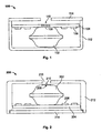
- the construction and mode of operation of the gas sensor arrangement 100 according to the invention will be described below with reference to FIG. 1 be explained in more detail.
- the components that are specific for the signal generation of the sensors such as the radiation source or the detector unit, are not shown here, in order to preserve the clarity.
- the integration of the filter into the substrate according to the invention is particularly advantageous when used for an infrared gas sensor, in particular a CO 2 sensor, but in no way limited to this special case.
- the gas sensor arrangement 100 has a measuring chamber 102, which is also referred to below as a cuvette, which has an inlet opening 108 for the inlet of the measuring gas into the measuring chamber 102.
- the measuring chamber 102 is mounted on a substrate 104 such that the inlet opening 108 is covered by a filter 110 integrated in the substrate.
- the substrate 104 is, for example, a printed circuit board (PCB) that is populated with various electronic components 106 in surface mount device (SMD) technology.
- the filter 110 is realized by a plurality of fine bores, which are introduced for example by means of a laser.
- a flexible printed circuit board with a laminated membrane filter or a ceramic printed circuit board with corresponding integrated filter structures can be used.
- a significant advantage of the filter function integrated into the substrate 104 according to the invention is, above all, that the surrounding housing 112 can be designed completely without additional openings.
- the housing opening 116 can be provided in a cover 114 which, owing to its essentially planar geometry, can be structured much more simply than the three-dimensional surrounding housing 112.
- the cover 114 it is also possible to completely dispense with the cover 114, because the electronic components 106 and the measuring chamber 102 are located on a side of the substrate 104 facing away from the environment, and the housing and substrate can therefore be made so accurate that the substrate functions as a cover can meet and yet no unwanted leaks occur.
- reference numeral description 200 Measuring chamber, cuvette 204 substratum 206 Electronic components 208 inlet opening 210 membrane filter 212 surrounding housing 214 cover 216 housing opening 100 Gas sensor arrangement 102 measuring chamber 104 substratum 106 Electronic components 108 inlet opening 110 filter 112 surrounding housing 114 cover 116 housing opening
Landscapes
- Physics & Mathematics (AREA)
- Health & Medical Sciences (AREA)
- Life Sciences & Earth Sciences (AREA)
- Chemical & Material Sciences (AREA)
- Analytical Chemistry (AREA)
- Biochemistry (AREA)
- General Health & Medical Sciences (AREA)
- General Physics & Mathematics (AREA)
- Immunology (AREA)
- Pathology (AREA)
- Spectroscopy & Molecular Physics (AREA)
- Investigating Or Analysing Materials By Optical Means (AREA)
Abstract
Description
Die vorliegende Erfindung bezieht sich auf eine Gassensoranordnung zum Nachweis mindestens eines Analyten in einem Messgas sowie auf ein Substrat, auf dem eine Messkammer der Gassensoranordnung montierbar ist.The present invention relates to a gas sensor arrangement for detecting at least one analyte in a measurement gas and to a substrate, on which a measuring chamber of the gas sensor arrangement can be mounted.
Die vorliegende Erfindung ist insbesondere in Zusammenhang mit Gassensoranordnungen einsetzbar, die mindestens eine Strahlung emittierende Strahlungsquelle, eine Messkammer, die mit einem Messgas, das einen zu messenden Analyten enthält, befüllbar ist, und mindestens eine die Strahlung detektierende Detektoreinrichtung aufweist, die ein von der Anwesenheit und/oder der Konzentration des Analyten abhängiges Ausgangssignal erzeugt.The present invention can be used in particular in connection with gas sensor arrangements which have at least one radiation-emitting radiation source, a measurement chamber which can be filled with a measurement gas containing an analyte to be measured, and at least one radiation-detecting detector which detects the presence of radiation and / or the concentration of the analyte dependent output signal generated.
Derartige Gassensoren sind für den Nachweis verschiedenster Analyte, beispielsweise Methan oder Kohlendioxid, bekannt. Dabei basieren solche Gassensoren, wie sie beispielsweise in der
So genannte "Non Dispersive Infrared" (NDIR)-Gassensoren weisen eine Infrarotstrahlungsquelle, eine als Absorptionsstrecke dienende Messkammer und einen Strahlungsdetektor auf. Die von dem Strahlungsdetektor gemessene Strahlungsintensität ist ein Maß für die Konzentration des absorbierenden Gases. Meist wird eine breitbandige Strahlungsquelle verwendet und über ein Interferenzfilter oder Gitter kann die interessierende Wellenlänge eingestellt werden. Alternativ kann auch eine selektive Strahlungsquelle, beispielsweise eine lichtemittierende Diode oder ein Laser, in Kombination mit nichtwellenlängenselektiven Strahlungsempfängern eingesetzt werden.So-called "Non Dispersive Infrared" (NDIR) gas sensors have an infrared radiation source, a measuring chamber serving as an absorption path and a radiation detector. The radiation intensity measured by the radiation detector is a measure of the concentration of the absorbing gas. In most cases, a broadband radiation source is used and the wavelength of interest can be adjusted via an interference filter or grating. Alternatively, a selective radiation source, for example a light-emitting diode or a laser, can be used in combination with non-wavelength-selective radiation receivers.
Insbesondere die Kohlendioxiddetektion gewinnt im Kraftfahrzeugbereicht zunehmend an Bedeutung. Dies ist zum einen dadurch bedingt, dass in Kraftfahrzeugen zur Erhöhung der Energieeffizienz bei Heizung und Klimatisierung der CO2-Gehalt der Innenraumluft überwacht wird, um nur bei Bedarf, d. h. bei erhöhter CO2-Konzentration, eine Frischluftzufuhr über eine entsprechende Lüfterklappenansteuerung zu veranlassen. Zum anderen basieren moderne Klimaanlagen auf CO2 als Kühlmittel. Daher können CO2-Gassensoren eine Überwachungsfunktion im Zusammenhang mit austretendem CO2 bei eventuellen Defekten erfüllen.In particular, the detection of carbon dioxide is becoming increasingly important in the motor vehicle sector. This is due to the fact that in motor vehicles to increase the energy efficiency of heating and air conditioning, the CO 2 content of the indoor air is monitored to cause only when needed, ie at elevated CO 2 concentration, a fresh air supply via a corresponding fan door control. On the other hand, modern air conditioning systems are based on CO 2 as a coolant. Therefore, CO 2 gas sensors can fulfill a monitoring function in connection with escaping CO 2 in case of defects.
Insbesondere im Kraftfahrzeugbereich müssen derartige Sensoren höchste Anforderungen an Robustheit, Zuverlässigkeit und Miniaturisierbarkeit erfüllen.Especially in the automotive sector, such sensors must meet the highest requirements for robustness, reliability and miniaturization.
Eine schematische Darstellung einer bekannten Gassensoreinheit, wie sie beispielsweise aus der
Dabei ist die Messkammer 202 der bekannten Gassensoranordnung 200 üblicherweise auf einem Substrat 204 aufgebaut. Meist handelt es sich bei dem Substrat 204 um eine gedruckte Leiterplatte, ein sogenanntes Printed Circuit Board (PCB). Auf dem Substrat 204 können neben der Messkammer 202 verschiedene elektronische Komponenten 206 montiert und über gedruckte Leiterbahnen, die hier nicht dargestellt sind, miteinander verbunden sein. Insbesondere können innerhalb der Messkammer 202 (entsprechend der Anordnung aus der
Die Messkammer 202 hat eine Eintrittsöffnung 208, durch welche hindurch das Messgas in die Messkammer eindringen kann. Bei üblichen Gassensoranordnungen 200 ist die Eintrittsöffnung 208 mit einem eingeschweißten Membranfilter 210 abgedeckt. Dieser Filter ist erforderlich, damit Schmutz und Störkomponenten nicht in die Messkammer 202 eindringen und das Messergebnis verfälschen können. Zum Schutz der Messkammer 210, die im Folgenden auch als Küvette bezeichnet wird, sowie der elektronischen Komponenten 206 wird die bekannte Gassensoranordnung 200 in der Regel von einem Umgehäuse 212 umgeben, das meist durch einen Deckel 214 geschlossen wird. Eine Gehäuseöffnung 216 sorgt für den Kontakt der Eintrittsöffnung 208 mit der zu analysierenden Umgebung.The
Bei der in
Das Umgehäuse besitzt ein Innenvolumen VG (in mm3), wobei alle, beispielsweise durch die Bauelemente 206, die Messkammer 202 und das Substrat 204, beanspruchten Volumina dabei schon abgezogen sind. Die aktive Fläche zum Gasaustausch mit der Umgebung sei BMess (in mm2). Zur Umgebung hat das Umgehäuse 212 ein Gesamtleck BLeck (in mm2). Weiterhin existiert zwischen dem Umgehäuse 212 und der Messkammer 202 nicht nur das unbeabsichtigte Leck ALeck, sondern je nach Konstruktion auch das vorhandene Leck CLeck (in mm2) an der Gasaustauschöffnung zur Umgebung.The surrounding housing has an inner volume VG (in mm 3), all of which are already stripped off, for example, by the
Das zu messende Gas kann prinzipiell auf drei verschiedene Arten in das zur Messung maßgebliche Küvettenvolumen VK gelangen: Mit A ist die laminare Vorbeiströmung und Diffusion an der Grenzschicht zur Gehäuseoberfläche symbolisiert. Mit B wird ein turbulentes Anblasen aus frontaler Richtung gekennzeichnet und mit C die Diffusion aus allen Raumrichtungen bezeichnet.In principle, the gas to be measured can reach the cuvette volume VK which is decisive for the measurement in three different ways: A is the laminar flow through and diffusion at the boundary layer to the housing surface. B denotes turbulent blowing from the frontal direction and C denotes diffusion from all spatial directions.
Die bereits angesprochene Erhöhung der Zeitkonstante t90 für das Ansprechen der Sensoranordnung auf eine Änderung der Gaskonzentration ergibt sich durch die gebildeten umschlossenen Mischvolumina, die immer größer sind als das Messvolumen in der Messkammer 202, und die gleichzeitig begrenzte Messöffnung, die den Gasaustausch behindert.The already mentioned increase in the time constant t90 for the response of the sensor arrangement to a change in the gas concentration results from the formed enclosed mixing volumes, which are always larger than the measuring volume in the
Da eine möglichst kleine Zeitkonstante t90 wünschenswert ist, bedeutet dies, dass die Messkammer außer an der Eintrittsöffnung 208 dicht sein muss, die durch den Filter begrenzte effektive Eintrittsöffnung möglichst groß sein muss und dass das Umgehäuse 212 möglichst offen gestaltet werden muss, um über die Leckraten in die Messkammer keinen verfälschenden Einfluss auszuüben. Damit wird aber gleichzeitig die Schutzfunktion des Gehäuses 212 reduziert.Since the smallest possible time constant t90 is desirable, this means that the measuring chamber has to be tight except at the inlet opening 208, the effective inlet opening delimited by the filter must be as large as possible and that the surrounding
Die Erfahrungen mit den bekannten Lösungen gemäß
Es besteht daher das Bedürfnis, eine Gassensoranordnung zu entwickeln, welche die beschriebenen Probleme mit den bekannten Anordnungen überkommt und eine möglichst kurze Ansprechzeit des Sensors bei gleichzeitig einfacher und kostengünstiger Herstellbarkeit gewährleistet.There is therefore a need to develop a gas sensor arrangement, which overcomes the problems described with the known arrangements and ensures the shortest possible response time of the sensor at the same time simple and cost manufacturability.
Somit besteht die Aufgabe, die der vorliegenden Erfindung zugrunde liegt, darin, eine verbesserte Gassensoranordnung anzugeben, die bei verringerter Ansprechzeit eine robuste und kompakte Bauweise sowie eine kostengünstige Herstellbarkeit besitzt.Thus, the object underlying the present invention, is to provide an improved gas sensor assembly, which has a reduced response time a robust and compact design and cost manufacturability.
Diese Aufgabe wird durch eine Gassensoranordnung mit den Merkmalen des Patentanspruchs 1, ein Substrat mit den Merkmalen des Patentanspruchs 15 sowie ein Herstellungsverfahren mit den Schritten des Patentanspruchs 21 gelöst. Vorteilhafte Weiterbildungen der vorliegenden Erfindung sind Gegenstand der abhängigen Patentansprüche.This object is achieved by a gas sensor arrangement having the features of patent claim 1, a substrate having the features of patent claim 15, and a production method having the steps of patent claim 21. Advantageous developments of the present invention are the subject of the dependent claims.
Dabei basiert die vorliegende Erfindung auf dem Grundgedanken, den erforderlichen Filter in dem Substrat zu integrieren und die Messkammer so auf dem Substrat zu montierten, dass die Eintrittsöffnung von dem Filter abgedeckt ist. Mit dieser erfindungsgemäßen Lösung kann die Messkammer wesentlich einfacher und damit dicht ausgeführt werden. Die Gesamtkonstruktion wird signifikant reduziert und es ergibt sich eine deutliche Kosteneinsparung. Aufgrund der verringerten Leckstellen kann die Zeitkonstante für das Ansprechen der Gassensoranordnung in vorteilhafter Weise verkürzt werden.The present invention is based on the idea of integrating the required filter in the substrate and mounting the measuring chamber on the substrate so that the inlet opening is covered by the filter. With this solution according to the invention, the measuring chamber can be made much simpler and thus tight. The overall construction is significantly reduced and results in a significant cost savings. Due to the reduced leaks, the time constant for the response of the gas sensor arrangement can be shortened in an advantageous manner.
Gemäß einer vorteilhaften Ausführungsform der vorliegenden Erfindung ist der Filter durch Öffnungen gebildet, die durch das Substrat hindurch verlaufen, wobei die Querschnittsfläche der Öffnungen im Verhältnis zu ihrer longitudinalen Ausdehnung so gewählt ist, dass die Störkomponenten aufgrund von Oberflächenspannungseffekten zurückgehalten werden. Auf diese Weise kann besonders einfach und effektiv eine Filterfunktion unmittelbar durch das Material des Substrats selbst erzielt werden und ein zusätzlicher Filter sowie der damit verbundene Montagevorgang können eingespart werden.According to an advantageous embodiment of the present invention, the filter is formed by apertures extending through the substrate, the cross-sectional area of the apertures being chosen in proportion to their longitudinal extent so as to retain the interfering components due to surface tension effects. In this way, a filter function can be achieved particularly easily and effectively directly by the material of the substrate itself and an additional filter and the associated assembly process can be saved.
Beispielsweise bei Verwendung einer in SMD-Technik bestückten Leiterplatte können mit Hilfe von Lasersystemen auf kostengünstige Weise sehr feine und gleichzeitig tiefe Löcher, so genannte Mikrovias, in Leiterplatten gebohrt werden. Mit Hilfe der Lasertechnik können die Lochdurchmesser im Vergleich zur Leiterplattendicke so klein gehalten werden, dass die Oberflächenspannungen der in Frage kommenden Reagenzien ein Eindringen derselben verhindern. Dabei kann der integrierte Filter während des etablierten Substratherstellungsprozesses ohne zusätzliche Arbeitsschritte realisiert werden, da Durchkontaktierungen ohnehin vorgesehen werden müssen.For example, when using a circuit board equipped with SMD technology, very fine and at the same time deep holes, so-called microvias, can be drilled in printed circuit boards in a cost-effective manner using laser systems. With the help of laser technology, the hole diameters compared to the PCB thickness can be kept so small that the surface tensions of the candidate reagents prevent penetration thereof. In this case, the integrated filter can be realized during the established substrate production process without additional work steps, since plated-through holes must be provided anyway.
Ein Umgehäuse, das die elektronischen Bauteile und die Messkammer mechanisch schützt, kann ohne jede Öffnung vorgesehen werden und ist daher in der Herstellung äußerst kostengünstigA surrounding housing, which mechanically protects the electronic components and the measuring chamber, can be provided without any opening and is therefore extremely cost-effective to manufacture
Anhand der in den beiliegenden Zeichnungen dargestellten vorteilhaften Ausgestaltungen wird die Erfindung im Folgenden näher erläutert. Es zeigen:
- Figur 1
- eine schematische Schnittdarstellung einer erfindungsgemäßen Gassensoranordnung;
- Figur 2
- eine schematische Schnittanordnung einer bekannten Gassensoranordnung;
- Figur 3
- eine schematische Übersicht über die bei Gassensoren beteiligten Flächen, Volumina und Strömungsverhältnisse.
- FIG. 1
- a schematic sectional view of a gas sensor arrangement according to the invention;
- FIG. 2
- a schematic sectional arrangement of a known gas sensor arrangement;
- FIG. 3
- a schematic overview of the areas involved in gas sensors, volumes and flow conditions.
Der Aufbau und die Wirkungsweise der erfindungsgemäßen Gassensoranordnung 100 soll im Folgenden mit Bezug auf
Wie in
In der hier gezeigten Ausführungsform ist das Substrat 104 beispielsweise eine gedruckt Leiterplatte (Printed Circuit Board, PCB), die in oberflächenmontierbarer Technik (Surface Mount Device, SMD) mit verschiedenen elektronischen Bauteilen 106 bestückt ist. Der Filter 110 ist durch eine Vielzahl von feinen Bohrungen, die beispielsweise mittels eines Lasers eingebracht werden, realisiert.In the embodiment shown here, the
Dabei werden diese sehr feinen und gleichzeitig tiefen Löcher in ihren Abmessungen so gewählt, dass der Lochdurchmesser im Vergleich zur Leiterplattendicke klein genug ist, um ein Eindringen von Störkomponenten über die Oberflächenspannungen zu verhindern. Selbstverständlich können aber auch andere Möglichkeiten, einen integrierten Filter bereitzustellen, genutzt werden.These very fine and deep holes are chosen in their dimensions so that the hole diameter compared to the PCB thickness is small enough to prevent ingress of interfering components on the surface tensions. Of course, other ways to provide an integrated filter can be used.
Beispielsweise kann eine flexible Leiterplatte mit einem laminierten Membranfilter oder eine Keramikleiterplatte mit entsprechenden integrierten Filterstrukturen verwendet werden.For example, a flexible printed circuit board with a laminated membrane filter or a ceramic printed circuit board with corresponding integrated filter structures can be used.
Ein wesentlicher Vorteil der erfindungsgemäßen in das Substrat 104 integrierten Filterfunktion besteht vor allem darin, dass das Umgehäuse 112 ganz ohne zusätzliche Öffnungen ausgeführt werden kann. Die Gehäuseöffnung 116 kann bei dieser Variante in einem Deckel 114 vorgesehen sein, der aufgrund seiner im Wesentlichen planen Geometrie deutlich einfacher strukturiert werden kann als das dreidimensional Umgehäuse 112.A significant advantage of the filter function integrated into the
Alternativ kann aber auch komplett auf den Deckel 114 verzichtet werden, weil die elektronischen Komponenten 106 und die Messkammer 102 sich auf einer der Umgebung abgewandten Seite des Substrats 104 befinden und Gehäuse und Substrat deshalb so passgenau ausgestaltet werden können, dass das Substrat die Funktion eines Deckels erfüllen kann und dennoch keine unerwünschten Lecks auftreten.Alternatively, it is also possible to completely dispense with the
Die Herstellung des integrierten Filters mit Hilfe von Laserbohrungen bietet die der Lasertechnik inhärenten Vorteile: keine mechanische Krafteinwirkung auf das Werkstück, minimale wärmebeeinflusste Zone, hohe Bearbeitungsgeschwindigkeiten, beliebige Konturbearbeitung, optimale Werkstoffausnutzung, hohe Flexibilität, hohe Reproduzierbarkeit und Qualität, sowie ein optimales Kostennutzenverhältnis.The production of the integrated filter with the help of laser drilling offers the advantages inherent in laser technology: no mechanical force on the workpiece, minimal heat-affected zone, high processing speeds, any contour machining, optimum material utilization, high flexibility, high reproducibility and quality, as well as an optimal cost-benefit ratio.
Claims (26)
Applications Claiming Priority (1)
| Application Number | Priority Date | Filing Date | Title |
|---|---|---|---|
| DE102007006155A DE102007006155A1 (en) | 2007-02-07 | 2007-02-07 | Substrate with integrated filter for gas sensor arrangements |
Publications (1)
| Publication Number | Publication Date |
|---|---|
| EP1956363A1 true EP1956363A1 (en) | 2008-08-13 |
Family
ID=39387113
Family Applications (1)
| Application Number | Title | Priority Date | Filing Date |
|---|---|---|---|
| EP08001755A Withdrawn EP1956363A1 (en) | 2007-02-07 | 2008-01-30 | Substrate with integrated filter for gas sensor assemblies |
Country Status (2)
| Country | Link |
|---|---|
| EP (1) | EP1956363A1 (en) |
| DE (1) | DE102007006155A1 (en) |
Cited By (1)
| Publication number | Priority date | Publication date | Assignee | Title |
|---|---|---|---|---|
| EP3748260A1 (en) * | 2019-06-05 | 2020-12-09 | Carrier Corporation | Enclosure for gas detector |
Citations (6)
| Publication number | Priority date | Publication date | Assignee | Title |
|---|---|---|---|---|
| US5834777A (en) * | 1994-02-14 | 1998-11-10 | Telaire Systems, Inc. | NDIR gas sensor |
| GB2392721A (en) * | 2002-09-03 | 2004-03-10 | E2V Tech Uk Ltd | Gas sensors |
| DE10360215A1 (en) * | 2003-12-20 | 2005-07-28 | Robert Bosch Gmbh | gas sensor |
| DE102004007946A1 (en) | 2004-02-18 | 2005-09-15 | Tyco Electronics Raychem Gmbh | Gas sensor arrangement in integrated design |
| DE102005000616A1 (en) * | 2005-01-03 | 2006-07-13 | Robert Bosch Gmbh | Gas sensor module |
| DE102005055860B3 (en) * | 2005-11-23 | 2007-05-10 | Tyco Electronics Raychem Gmbh | Gas sensor arrangement with light channel in the form of a conical section rotational body |
Family Cites Families (3)
| Publication number | Priority date | Publication date | Assignee | Title |
|---|---|---|---|---|
| US6410918B1 (en) * | 1997-10-28 | 2002-06-25 | Edwards Systems Technology, Inc. | Diffusion-type NDIR gas analyzer with improved response time due to convection flow |
| US6469303B1 (en) * | 2000-05-17 | 2002-10-22 | Rae Systems, Inc. | Non-dispersive infrared gas sensor |
| US7041256B2 (en) * | 2001-01-30 | 2006-05-09 | Industrial Scientific Corporation | Poison resistant combustible gas sensors and method for warning of poisoning |
-
2007
- 2007-02-07 DE DE102007006155A patent/DE102007006155A1/en not_active Ceased
-
2008
- 2008-01-30 EP EP08001755A patent/EP1956363A1/en not_active Withdrawn
Patent Citations (6)
| Publication number | Priority date | Publication date | Assignee | Title |
|---|---|---|---|---|
| US5834777A (en) * | 1994-02-14 | 1998-11-10 | Telaire Systems, Inc. | NDIR gas sensor |
| GB2392721A (en) * | 2002-09-03 | 2004-03-10 | E2V Tech Uk Ltd | Gas sensors |
| DE10360215A1 (en) * | 2003-12-20 | 2005-07-28 | Robert Bosch Gmbh | gas sensor |
| DE102004007946A1 (en) | 2004-02-18 | 2005-09-15 | Tyco Electronics Raychem Gmbh | Gas sensor arrangement in integrated design |
| DE102005000616A1 (en) * | 2005-01-03 | 2006-07-13 | Robert Bosch Gmbh | Gas sensor module |
| DE102005055860B3 (en) * | 2005-11-23 | 2007-05-10 | Tyco Electronics Raychem Gmbh | Gas sensor arrangement with light channel in the form of a conical section rotational body |
Cited By (2)
| Publication number | Priority date | Publication date | Assignee | Title |
|---|---|---|---|---|
| EP3748260A1 (en) * | 2019-06-05 | 2020-12-09 | Carrier Corporation | Enclosure for gas detector |
| US11662109B2 (en) | 2019-06-05 | 2023-05-30 | Carrier Corporation | Enclosure for gas detector |
Also Published As
| Publication number | Publication date |
|---|---|
| DE102007006155A1 (en) | 2008-08-14 |
Similar Documents
| Publication | Publication Date | Title |
|---|---|---|
| DE102005055860B3 (en) | Gas sensor arrangement with light channel in the form of a conical section rotational body | |
| DE102004044145B3 (en) | Reflector module for a photometric gas sensor | |
| EP1697724B1 (en) | Gas sensor | |
| DE102004007946A1 (en) | Gas sensor arrangement in integrated design | |
| DE102006054165B3 (en) | Optical sensor i.e. hydrogen sensor, arrangement for detecting hydrogen in gaseous measuring medium, has transducer designed such that physical characteristic is changed in response to presence and/or concentration of analyte | |
| EP2307881B1 (en) | Gas sensor, produced by flip-chip method | |
| DE102008053083B4 (en) | Infrared light detector and production thereof | |
| DE102004044702B4 (en) | Oil mist detection device | |
| WO1991011702A1 (en) | Device for determining the composition of fluids, in particular the constituents of exhaust gases of internal combustion engines | |
| DE10121185B4 (en) | Optical sensor | |
| DE102015207788A1 (en) | Micromechanical sensor device | |
| DE102005022288B4 (en) | Gas sensor arrangement and measuring method for improving the long-term stability | |
| DE102010031919B4 (en) | Measuring probe for a sensor for analyzing a medium by means of infrared spectroscopy and a method for manufacturing the measuring probe | |
| DE102009008062A1 (en) | gas sensor | |
| EP1956363A1 (en) | Substrate with integrated filter for gas sensor assemblies | |
| EP0740146B1 (en) | Device for detecting a gas or aerosol | |
| WO2004097381A1 (en) | Gas sensor for a motor vehicle air-conditioning unit | |
| EP3093633B1 (en) | Apparatus for the simultaneous detection of a plurality of distinct materials and/or substance concentrations | |
| DE102007006153A1 (en) | Optical gas sensor arrangement for use in motor vehicle, has detector device detecting changed radiation intensity in end region of reaction section, and producing output signal in dependence of presence of analyte in reaction path | |
| DE102008011304B4 (en) | Temperature measurement unit | |
| WO2006072492A1 (en) | Gas sensor module | |
| DE102004010757A1 (en) | Infrared sensor for measurement of gas concentration, has ellipsoidal reflector chamber with IR source and IR detector mounted on base plate at focii of ellipsoid | |
| DE102004001357A1 (en) | Oil mist detection device | |
| DE10261102A1 (en) | Rain sensor, in particular for a motor vehicle and method for its production | |
| DE102013103024B4 (en) | LED module with ventilation and degassing device |
Legal Events
| Date | Code | Title | Description |
|---|---|---|---|
| PUAI | Public reference made under article 153(3) epc to a published international application that has entered the european phase |
Free format text: ORIGINAL CODE: 0009012 |
|
| AK | Designated contracting states |
Kind code of ref document: A1 Designated state(s): AT BE BG CH CY CZ DE DK EE ES FI FR GB GR HR HU IE IS IT LI LT LU LV MC MT NL NO PL PT RO SE SI SK TR |
|
| AX | Request for extension of the european patent |
Extension state: AL BA MK RS |
|
| AKX | Designation fees paid | ||
| STAA | Information on the status of an ep patent application or granted ep patent |
Free format text: STATUS: THE APPLICATION IS DEEMED TO BE WITHDRAWN |
|
| 18D | Application deemed to be withdrawn |
Effective date: 20090214 |
|
| REG | Reference to a national code |
Ref country code: DE Ref legal event code: 8566 |