EP1951159B1 - Percutaneous transpedicular access, fusion, discectomy, and stabilization system - Google Patents
Percutaneous transpedicular access, fusion, discectomy, and stabilization system Download PDFInfo
- Publication number
- EP1951159B1 EP1951159B1 EP06838283.7A EP06838283A EP1951159B1 EP 1951159 B1 EP1951159 B1 EP 1951159B1 EP 06838283 A EP06838283 A EP 06838283A EP 1951159 B1 EP1951159 B1 EP 1951159B1
- Authority
- EP
- European Patent Office
- Prior art keywords
- cannula
- channel
- offset
- guide pin
- longitudinal axis
- Prior art date
- Legal status (The legal status is an assumption and is not a legal conclusion. Google has not performed a legal analysis and makes no representation as to the accuracy of the status listed.)
- Active
Links
Images


Classifications
-
- A—HUMAN NECESSITIES
- A61—MEDICAL OR VETERINARY SCIENCE; HYGIENE
- A61B—DIAGNOSIS; SURGERY; IDENTIFICATION
- A61B17/00—Surgical instruments, devices or methods, e.g. tourniquets
- A61B17/16—Bone cutting, breaking or removal means other than saws, e.g. Osteoclasts; Drills or chisels for bones; Trepans
- A61B17/1637—Hollow drills or saws producing a curved cut, e.g. cylindrical
-
- A—HUMAN NECESSITIES
- A61—MEDICAL OR VETERINARY SCIENCE; HYGIENE
- A61B—DIAGNOSIS; SURGERY; IDENTIFICATION
- A61B17/00—Surgical instruments, devices or methods, e.g. tourniquets
- A61B17/16—Bone cutting, breaking or removal means other than saws, e.g. Osteoclasts; Drills or chisels for bones; Trepans
- A61B17/1662—Bone cutting, breaking or removal means other than saws, e.g. Osteoclasts; Drills or chisels for bones; Trepans for particular parts of the body
- A61B17/1671—Bone cutting, breaking or removal means other than saws, e.g. Osteoclasts; Drills or chisels for bones; Trepans for particular parts of the body for the spine
-
- A—HUMAN NECESSITIES
- A61—MEDICAL OR VETERINARY SCIENCE; HYGIENE
- A61B—DIAGNOSIS; SURGERY; IDENTIFICATION
- A61B17/00—Surgical instruments, devices or methods, e.g. tourniquets
- A61B17/16—Bone cutting, breaking or removal means other than saws, e.g. Osteoclasts; Drills or chisels for bones; Trepans
- A61B17/17—Guides or aligning means for drills, mills, pins or wires
- A61B17/1739—Guides or aligning means for drills, mills, pins or wires specially adapted for particular parts of the body
- A61B17/1757—Guides or aligning means for drills, mills, pins or wires specially adapted for particular parts of the body for the spine
Definitions
- the invention relates generally to orthopedic boney fusion, discectomy, and stabilization systems, and more particularly, to percutaneous fusion, discectomy, and stabilization systems and methods.
- the present invention includes apparatus for accessing the disc space between an inferior and superior vertebra via a transpedicular approach in the inferior vertebra including creating a channel normal to the pedicle and using an offset guide to create a second transpedicular channel at an angle to the first, normal pedicle channel where the second transpedicular channel passes into the disc space.
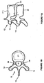
- FIG. 1A is a simplified sagittal view of a vertebrae pair 20, 21.
- FIG. 1B is a simplified, sectional coronal view of the vertebrae 21 of the vertebrae pair shown in FIG. 1A .
- Each vertebra 20, 21 includes lamina 12, transverse processes 14, a spinous process 16, central canal 10, and pedicles 24.
- a disc 22 comprised of an annulus and disc nucleus (not shown) is located between the vertebrae pair 20, 21. Due to disc degeneration, expulsion, annulus tears, or other conditions, the spinal cord that passes through the central canal 10 may become compressed causing patient discomfort. It may be desirable to modify or fix the spatial relationship between the vertebrae pair 20, 21.
- FIGS. 2A to 8F present various apparatus and methods for accessing the vertebrae pair 20, 21 to perform a surgical procedure.
- FIGS. 2A to 7D present apparatus for forming such a channel according to various example.
- a normal channel is first formed in the inferior vertebrae 20's pedicle.
- a second, offset channel is formed in the inferior vertebrae 20 based on the formed normal channel.
- the second, offset channel may enable access the disc space 22 or superior vertebrae 21.
- FIG. 2A is a simplified coronal view
- FIG. 2B is a simplified sagittal view
- FIG. 2C is a simplified posterior view
- FIG. 2D is an isometric view of the vertebrae pair 20, 21 including a guide pin or wire 30 and support sleeve 32 according to various examples.
- the guide pin 30 is inserted at a posterior, lateral angle from the coronal view and normal to the vertebrae 20 from the sagittal view.
- the guide pin extends into the vertebrae 20 pedicle 24 while not violating the pedicle wall.
- a support sleeve 32 may be inserted over the guide pin 30.
- the support sleeve 32 may be a thin walled cannula in an example of the present invention.
- FIG. 3A is a simplified isometric view of the vertebrae pair 20, 21 shown in FIG. 2D further including an obturator 36 and cannula 34 inserted over the guide pin 30 and support sleeve 32.
- the obturator 36 may be advanced toward a pedicle 24 to create a tissue pathway to the pedicle 24.
- FIG. 3B is a simplified isometric view of the vertebrae pair 20, 21 where the obturator 36 and guide sleeve 32 have been removed leaving the guide pin 30 inserted into the pedicle with the cannula 34 over the guide pin 30.
- FIG. 3C is a simplified isometric view of the vertebrae pair 20, 21 shown in FIG.
- the reamer 38 may be operatively advanced into the pedicle 24 to form a bore in the pedicle 24.
- the reamer 38 may have about a 5mm diameter and about an 8mm depth stop.
- the reamer 38 may be used to form an approximately 10mm deep, 5mm in diameter bore (39 shown in FIG. 4A ) in the pedicle 24, the bore 39 axis being approximately normal to the coronal plane of vertebrae 20.
- the cannula 34 may have a diameter of about 8.5mm.
- FIG. 4A is a simplified isometric view of the vertebrae pair 20, 21 where the cannulated reamer 38 and the cannula 34 have been removed leaving the guide pin 30 inserted in the bored pedicle according to various examples.
- FIG. 4B is a simplified isometric view of the vertebrae pair 20, 21 shown in FIG. 4A further including a cannulated spot facer 42 inserted over the guide pin 30.
- the spot facer 42 may be operatively advanced into the pedicle 24 to enlarge an upper section of the bore 39 formed in the pedicle 24.
- the spot facer 42 has about a 12mm diameter with a projected wall.
- the spot facer 42 forms a larger upper bore section to be occupied by a polyaxial or monoaxial pedicle receiving section, the section moveably coupled or couplable to a pedicle screw head.
- FIG. 4C is a simplified isometric view of the vertebrae pair 20, 21 where the cannulated spot facer 42 has been removed leaving the guide pin 30 inserted in the enlarged, bored pedicle according to various examples.
- FIG. 4D is a simplified isometric view of the vertebrae pair 20, 21 shown in FIG. 4C further including a slotted cannula 46 inserted over the guide pin 30, the cannula 46 being advanced into the pedicle bore 44 in the pedicle 24 according to various examples.
- FIG. 5A is a simplified sagittal view of the vertebrae pair 20, 21 shown in FIG. 4D further including a transpedicular channel alignment tool 50 inserted over the cannula according to various examples.
- the alignment tool 50 is aligned along the caudal-cephalad (sagittal plane).
- the tool 50 includes a normal port 54 and an offset port 52.
- the normal port is sized to receive the guide pin 30 or slotted cannula 46.
- FIG. 5B is a simplified sagittal view of the vertebrae pair 20, 21 where the guide pin 30 has been removed leaving the slotted cannula 46 inserted in pedicle bore 44 and transpedicular channel alignment tool 50 inserted over the cannula 46 according to various embodiments.
- the alignment tool's 50 normal port 54 is sized to receive the slotted cannula 46.
- the offset port 52 is oriented an angle to the normal port 54 about 20 degrees.
- FIG. 5C is a simplified sagittal view of the vertebrae pair 20, 21 shown in FIG. 5B further including an offset guide pin 56 with offset support sleeve 58 inserted through the transpedicular channel alignment tool's 50 offset guide port 52.
- the offset guide pin 56 is advanced at the offset angle from normal to the vertebrae pair 20, 21 into disc space. In an embodiment one or more X-rays may be taken and reviewed to determine whether the offset guide pin 56 is proceeding along a desired pathway in the pedicle 24 prior to advancement into the disc space 22.
- FIG. 5D is a simplified sagittal view of the vertebrae pair 20, 21 shown in FIG. 5C where the cannula 46 in the transpedicular channel alignment tool's normal guide port 54 has been removed leaving the guide pin and support sleeve inserted through the transpedicular channel alignment tool's 50 offset guide port 52 and the offset guide pin 56 advanced at the offset angle according to various embodiments.
- FIG. 6A is a simplified sagittal view of the vertebrae pair 20, 21 shown in FIG. 5D where the offset support sleeve 58 in the transpedicular channel alignment tool's 50 offset guide port 52 and the alignment tool 50 have been removed leaving the offset guide pin 56 inserted through a transpedicular channel to the disc space 22 according to various embodiments.
- the guide pin 56 tip 57 is projecting into the disc space 22.
- the transpedicular channel may be enlarged to enable different procedures to be performed in the disc space 22.
- the transpedicular channel is not adjacent or near any nerve pathways in an embodiment, reducing the risk of nerve related injuries due a procedure being performed in the disc space 22.
- FIG. 6B is a simplified sagittal view of the vertebrae pair 20, 21 shown in FIG. 6A further including a cannulated reamer 62 within a cannula 64 inserted over the offset guide pin 56.
- the reamer 62 may be operatively advanced into disc space via the transpedicular channel to enlarge the channel 66.
- the reamer 62 may be about a 5.5mm reamer to form a 5.5mm diameter channel 66 from the pedicle 24 of the inferior vertebra 20 to the disc space 22.
- FIG. 6C is a simplified sagittal view of the vertebrae pair 20, 21 shown in FIG. 6B where the cannulated reamer 62 and the cannula 64 have been removed leaving the guide pin 56 inserted through the enlarged transpedicular channel 66 to the disc space 22.
- FIG. 6D is a simplified sagittal view of the vertebrae pair shown in FIG. 6C further including a slotted cannula 68 and obturator 67 inserted over the offset guide pin 56.
- a tapered obturator 67 within a slotted, thin walled cannula 68 are inserted over the offset guide pin 56 into the disc space 22 via the transpedicular channel.
- the slotted cannula 68 has about a 5.5mm diameter to be accommodated by the channel 66 formed by the reamer 62.
- FIG. 6E is a simplified sagittal view of the vertebrae pair 20,21 shown in FIG.
- FIG. 6F is a simplified sagittal view of the vertebrae pair shown in FIG. 6B where bone granules 63 (allograft material) packed with a powered material 65 have been inserted into the disc space 22 via the cannula 68 according to various examples.
- FIGs. 6G and 6I depict the force vectors 61 as applied to the compacted granular-powered material 63,65 within a cannula 68 and disc space 22.
- the bone granules 63 may be packed with a powered material 65 to facilitate their passage into the disc space 22 via the cannula 68.
- the powered material 65 helps prevent the larger particles 63 from binding together and becoming wedged within a cannula 68 as passed there-through.
- the force vectors 61 may split at the cannula distal end as the powered material 65 and granules 63 become disassociated as the cannula 68 walls prevent earlier such disassociation.
- the powered material may be calcium sulfate, Plaster of Paris (calcium sulfate hemi-hydrate), finely pulverized cortical bone with decalcification, or similar fine material safe for insertion into the disc space 22 and possible absorption.
- the granules 63 may be a granular cortical or structural allograft material.
- the granules 63 may have a generally spherical geometry and maximum cross sectional area smaller than the cross section area of a delivery cannula 68.
- a binding agent may be employed to bind the powered material 65 and granules 65 including evaporated or saturated sugar or starch solution.
- the granular composite (65 and 63 and binding agent) may be fashioned into cylindrical pellets using a thermal and pressure modulated curing process. The resultant pellets may then be sterilely packaged.
- the cylindrical pellets may be packaged within a thin walled polymer material, e.g . "straws". Such packages (pellets with straws) may be inserted into a delivery cannula 68 or alternatively placed in automated delivery devices or systems. Such cylindrical pellets may be driven via linear forces 61 through the length of the cannula 68, without pellet dissociation or granular element binding. As noted once the composite (63, 65) exits the supportive cannula 68 walls additional forces (e.g. impact loading upon vertebra 20, 21 and disc annulus 22 may dissociate the granules 63.
- additional forces e.g. impact loading upon vertebra 20, 21 and disc annulus 22 may dissociate the granules 63.
- Such dissociation may form an expanding sphere of composite material, the sphere capable of effecting bone displacement or fracture site reduction and having load bearing capacity proportional to the material 63 density.
- the powered material 61-granules 65 composition may be used in cannulated procedures for intervertebral disc arthrodesis, vertebroplasty applications for vertebral compression fractures, periarticular depression fracture reductions and bone grafting, bone cyst therapies, etc.
- the alignment tool 50 may create an offset angle of about 20 degrees of normal that may be used to form a transpedicular pathway or channel to a disc space via an inferior vertebra 20. In another embodiment it may be desirable to access the lower endplate of the superior vertebra 21 in addition to the disc space 22.
- FIG. 7A is a simplified isometric view of the vertebrae pair 20, 21 shown in FIG. 4D further including an offset guide pin 56 with support sleeve 58 and second transpedicular channel alignment tool 90. In this embodiment the second alignment tool 90 creates an offset angle of about 35 degrees relative to the normal port 92.
- FIG. 7B is a simplified sagittal view of the vertebrae pair 20, 21 shown in FIG. 7A showing that the second offset angle from normal is greater than the offset angle show in FIGS. 5A to 5D according to various embodiments.
- FIG. 7C is a simplified sagittal view of the vertebrae pair 20, 21 shown in FIG. 7B where the cannula 46 in the second transpedicular channel alignment tool's 90 normal guide port 92 has been removed leaving the offset guide pin 56 and support sleeve 58 inserted through the transpedicular channel alignment tool's offset guide port 94. The offset guide pin 56 tip 57 has been inserted into the disc space 22.
- FIG. 7D is a simplified sagittal view of the vertebrae pair 20, 21 shown in FIG.
- FIG. 7E is a simplified sagittal view of the vertebrae pair 20, 21 having a cannulated compression-distraction screw 70 advanced over the offset guide pin or wire 56 through the disc space into the superior vertebra via a second transpedicular channel according to various embodiments.
- the compression-distraction screw 70 has distal thread 72, proximal thread 74, non-threaded central section 76, and locking ports 78.
- the distal thread 72 can be independently rotated via a head within the central section 76.
- the distal threaded portion 72 may have a sleeve within the central section 76 so the portion 72 may extend away or toward the portion 74.
- FIG. 7F is a simplified sagittal view of the vertebrae pair 20, 21 having a fusion construct 80 advanced through the inferior vertebra 20 and disc space 22 into the superior vertebra 23 via the second transpedicular channel according to various embodiments.
- the construct 80 is a bone dowel having a proximal 84 and distal end 82.
- the bone dowel's 80 distal end 82 may be embedded into the superior vertebra 21 endplate 23 and its proximal end 84 in the inferior vertebra.
- a portion of the disc 22 may be removed and replaced with implants, bone growth materials, or allograft material prior to the fusion construct 80 insertion/implantation.
- the transpedicular channel into the superior vertebra 21 may also be used to perform kyphoplasty and other vertebra height restoration and modification procedures.
- FIG. 8A is a simplified isometric view of the vertebrae pair shown in FIG. 6D including a reverse pedicle alignment tool 80 inserted over the offset cannula 68 according to various embodiments.
- the reverse pedicle alignment tool 80 includes an offset guide port 82 and a normal guide port 84.
- the offset guide port 82 is sized to fit the offset cannula 68.
- FIG. 8B is a simplified isometric view of the vertebrae pair shown in FIG. 8A including the guide pin 30 inserted in the reverse alignment tool's 80 normal guide port 84. In an embodiment the guide pin 30 passes through the cannula 68 slot 69.
- FIG. 8C is a simplified isometric view of the vertebrae pair 20, 21 shown in FIG. 8B where the offset cannula 68 has been removed and the guide pin 30 has been advanced into the pedicle normal channel 45 according to various embodiments.
- FIG. 8D is a simplified isometric view
- FIG. 8E is a simplified sagittal view
- FIG. 8F is a simplified coronal view of the vertebrae pair 20, 21 shown in FIG. 8C where the reverse pedicle alignment tool 80 has been removed leaving the guide pin 30 in the channel 45 according to various embodiments.
- the guide pin 30 may then be used to access the normal pedicle channel 45 to perform one or more procedures via the normal pedicle channel 45, e.g., insertion of a pedicle screw as part fixation instrumentation.
- FIGS. 9A to 9F are diagrams of another transpedicular channel alignment and access tool system 200 according to claim 1.
- the system 200 may include a length or extension adjustable, slotted 216, cannula 210, a cannula offset tool 220, a handle 230, and an extension or length adjustment knob 240 for the cannula 210.
- the handle 230 may transversely (relative to cannula 10) engage the offset tool 220 via a bore 228 and handle extension 232.
- the offset tool 220 may include a first cannula channel 223 for cannula 210, a second channel 222 for a cannula or guide wire, a guide wire release slot 224, and a flange 228 for engaging one or more tabs 242 of the knob 240.
- the handle 230 may include a larger, distal section 234.
- the channel 224 and cannula 210 slot 216 may be conFIG.d so a guide wire or other tool inserted into the channel 224 may pass through the cannula 210 via the slot 216.
- the system 200 may include a set pin or screw 229 in the offset tool 220 to fixably position the cannula 210 extension. As shown in FIG.
- the system 200 may also include a set pin or screw 227 in the offset tool 220 to releasably engage the handle 230 so the handle extension 232 may be removed from the tool 220 channel 228.
- FIG. 9F includes a partial cross sectional view of the offset tool 220 showing a riser 244 that may be coupled to the knob 240 to enable translation of the cannula 210 slot 216.
- FIGS. 10A to 10F are diagrams of the transpedicular channel alignment and access tool system 200 employed in a vertebra 20 according to various embodiments.
- the cannula 210 may be inserted normally to the spinal vertebra 20 pedicle.
- a guide wire 56 and cannula 58 may be placed with the slot 222 of the tool 200.
- the guide wire 56 and cannula 58 may be inserted into the spinal vertebra 20, disc space 22, or adjacent spinal vertebra 21 as a function of the cannula 210 slot 216 translation via the knob 40.
- the cannula 210 may have a guide wire 32 inserted therein to securely engage the cannula 210 in the spinal vertebra 20.
- the guide wire 32 may be partially removed to enable guide wire 56 or cannula 58 to pass through the cannula 210 slot 216 and into one of the spinal vertebra 20, disc space 22, and adjacent spinal vertebra 21.
- the knob 240 may be rotate to linearly translate the cannula 210.
- the cannula 210 translation may change the offset angle between the channel 222 and cannula 210.
- the offset between channel 222 and cannula 210 may enable a guide wire 58 or cannula 56 to engage the vertebra 20 when knob 240 is rotated to a first point.
- the offset between channel 222 and cannula 210 may enable a guide wire 58 or cannula 56 to engage the disc space 22 when knob 240 is rotated to a second point.
- the offset between channel 222 and cannula 210 may enable a guide wire 58 or cannula 56 to engage the adjacent vertebra 21 when knob 240 is rotated to a third point.
- the inferior vertebrae 20 may be the sacrum and the superior vertebrae 21 the adjacent vertebrae, L5 in humans.
Landscapes
- Health & Medical Sciences (AREA)
- Surgery (AREA)
- Life Sciences & Earth Sciences (AREA)
- Orthopedic Medicine & Surgery (AREA)
- Biomedical Technology (AREA)
- Nuclear Medicine, Radiotherapy & Molecular Imaging (AREA)
- Oral & Maxillofacial Surgery (AREA)
- Engineering & Computer Science (AREA)
- Dentistry (AREA)
- Heart & Thoracic Surgery (AREA)
- Medical Informatics (AREA)
- Molecular Biology (AREA)
- Animal Behavior & Ethology (AREA)
- General Health & Medical Sciences (AREA)
- Public Health (AREA)
- Veterinary Medicine (AREA)
- Surgical Instruments (AREA)
Description
- 001 The invention relates generally to orthopedic boney fusion, discectomy, and stabilization systems, and more particularly, to percutaneous fusion, discectomy, and stabilization systems and methods.
- 002 Examples of devices for percutaneous fusion of vertebrae can be seen in document
DE 297 03 947 , whilst an example of a stabilization system for use in surgery is described inUS 5,324,295 . It is desirable to provide a percutaneous fusion, discectomy, and stabilization system that limits or prevent the risks of nerve injury or epineural fibrosis. The present invention provides such a system. - 003 The present invention includes apparatus for accessing the disc space between an inferior and superior vertebra via a transpedicular approach in the inferior vertebra including creating a channel normal to the pedicle and using an offset guide to create a second transpedicular channel at an angle to the first, normal pedicle channel where the second transpedicular channel passes into the disc space.
- 004 The features, objects, and advantages of the present invention will become more apparent from the detailed description set forth below when taken in conjunction with the drawings in which like reference characters identify correspondingly throughout and wherein:
- 005 FIG. IA is a simplified sagittal view of a vertebrae pair;
- 006 FIG. IB is a simplified, sectional coronal view a vertebrae;
- 007
FIG. 2A is a simplified coronal view of the vertebrae pair including a guide pin and support sleeve, the guide pin being inserted into a pedicle according to various examples; - 008
FIG. 2B is a simplified sagittal view of the vertebrae pair including a guide pin and support sleeve, the guide pin being inserted into a pedicle as shown inFIG. 2A ; - 009
FIG. 2C is a simplified posterior view of the vertebrae pair including a guide pin and support sleeve, the guide pin being inserted into a pedicle as shown inFIG. 2A ; - 010
FIG. 2D is a simplified isometric view of the vertebrae pair including a guide pin and support sleeve, the guide pin being inserted into a pedicle as shown inFIG. 2A ; - 011
FIG. 3A is a simplified isometric view of the vertebrae pair shown inFIG. 2D further including an obturator and cannula inserted over the guide pin and support sleeve, the obturator being advanced toward a pedicle to create a tissue pathway to the pedicle according to various examples; - 012
FIG. 3B is a simplified isometric view of the vertebrae pair where the obturator and guide sleeve have been removed leaving the guide pin inserted into the pedicle with the cannula over the guide pin according to various examples; - 013
FIG. 3C is a simplified isometric view of the vertebrae pair shown inFIG. 3B further including a cannulated reamer inserted over the guide pin and within the cannula, the reamer being operatively advanced into the pedicle to form a bore in the pedicle according to various examples; - 014
FIG. 4A is a simplified isometric view of the vertebrae pair where the cannulated reamer and the cannula have been removed leaving the guide pin inserted in the bored pedicle according to various examples; - 015
FIG. 4B is a simplified isometric view of the vertebrae pair shown inFIG. 4A further including a cannulated spot facer inserted over the guide pin, the spot facer being operatively advanced into the pedicle to enlarge the bore formed in the pedicle according to various examples; - 016
FIG. 4C is a simplified isometric view of the vertebrae pair where the cannulated spot facer has been removed leaving the guide pin inserted in the enlarged, bored pedicle according to various examples; - 017
FIG. 4D is a simplified isometric view of the vertebrae pair shown inFIG. 4C further including a slotted cannula inserted over the guide pin, the cannula being advanced into the pedicle bore in the pedicle according to various examples; - 018
FIG. 5A is a simplified sagittal view of the vertebrae pair shown inFIG. 4D further including a transpedicular channel alignment tool inserted over the cannula according to various embodiments; - 019
FIG. 5B is a simplified sagittal view of the vertebrae pair where the guide pin has been removed leaving the cannula inserted in pedicle bore and transpedicular channel alignment tool inserted over the cannula according to various embodiments; - 020
FIG. 5C is a simplified-sagittal view of the-vertebrae pair shown inFIG. 5B further including a guide pin with support sleeve, the guide pin and support sleeve being inserted through the transpedicular channel alignment tool's offset guide port and the guide pin advanced at an angle offset from normal to the vertebrae pair into disc space according to various embodiments; - 021
FIG. 5D is a simplified sagittal view of the vertebrae pair shown inFIG. 5C where the cannula in the transpedicular channel alignment tool's normal guide port has been removed leaving the guide pin and support sleeve inserted through the transpedicular channel alignment tool's offset guide port and the guide pin advanced at the offset angle according to various embodiments; - 022
FIG. 6A is a simplified sagittal view of the vertebrae pair shown inFIG. 5D where the support sleeve in the transpedicular channel alignment tool's offset guide port and the alignment tool have been removed leaving the guide pin inserted through a transpedicular channel to the disc space according to various examples; - 023
FIG. 6B is a simplified sagittal view of the vertebrae pair shown inFIG. 6A further including a cannulated reamer within a cannula inserted over the offset guide pin, the reamer being operatively advanced into disc space via the transpedicular channel to enlarge the channel according to various examples; - 024
FIG. 6C is a simplified sagittal view of the vertebrae pair shown inFIG. 6B where the cannulated reamer and the cannula have been removed leaving the guide pin inserted through the enlarged transpedicular channel to the disc space according to various examples; - 025
FIG. 6D fs a simplified sagittal view of the vertebrae pair shown inFIG. 6C further including a cannula inserted over the offset guide pin, the cannula being advanced into disc space via the transpedicular channel according to various examples; - 026
FIG. 6E is a simplified sagittal view of the vertebrae pair shown inFIG. 6B where the guide pin has been removed leaving the offset cannula in enlarged transpedicular channel to the disc space according to various examples; - 027
FIG. 6F is a simplified sagittal view of the vertebrae pair shown inFIG. 6B where bone granules have been inserted into the disc space via the cannula according to various examples; - 028
FIGS. 6G and 6I depict the force vectors as applied to a compacted granular-powered material within a cannula and a disc space according to various examples. - 029
FIG. 7A is a simplified isometric view of the vertebrae pair shown inFIG. 4D further including a guide pin with support sleeve and second transpedicular channel alignment tool, the guide pin and support sleeve being inserted through the second transpedicular channel alignment tool's offset guide port and the guide pin advanced at a second offset angle from normal to the vertebrae pair into disc space according to various embodiments; - 030
FIG. 7B is a simplified sagittal view of the vertebrae pair shown inFIG. 7A showing that the second offset angle from normal is greater than the offset angle show inFIGS. 5A to 5D according to various embodiments; - 031
FIG. 7C is a simplified sagittal view of the vertebrae pair shown inFIG. 7B where the cannula in the second transpedicular channel alignment tool's normal guide port has been removed leaving the guide pin and support sleeve inserted through the transpedicular channel alignment tool's offset guide port and the guide pin advanced at the second offset angle according to various embodiments; - 032
FIG. 7D is a simplified sagittal view of the vertebrae pair shown inFIG. 7C where the support sleeve in the second transpedicular channel alignment tool's offset guide port and the second alignment tool have been removed leaving the guide pin inserted through a transpedicular channel to the disc space according to various embodiments; - 033
FIG. 7E is a simplified sagittal view of the vertebrae pair having a cannulated compression-distraction screw advanced over the offset guide pin or wire through the disc space into the superior vertebra via a second transpedicular channel according to various embodiments; - 034
FIG. 7F is a simplified sagittal view of the vertebrae pair having a fusion construct advanced through the inferior vertebra and disc space into the superior vertebra via the second transpedicular channel according to various embodiments; - 035
FIG. 8A is a simplified isometric view of the vertebrae pair shown inFIG. 6D including a reverse pedicle alignment tool inserted over the offset cannula according to various embodiments; - 036
FIG. 8B is a simplified isometric view of the vertebrae pair shown inFIG. 8A including the guide pin inserted in the reverse alignment tool's normal port and through the cannula' slot according to various embodiments; - 037
FIG. 8C is a simplified isometric view of the vertebrae pair shown inFIG. 8B where the cannula has been removed and the guide pin has been advanced into the pedicle normal channel according to various embodiments; - 038
FIG. 8D is a simplified isometric view of the vertebrae pair shown inFIG. 8C where the reverse pedicle alignment tool has been removed according to various embodiments; - 039
FIG. 8E is a simplified sagittal view of the vertebrae pair shown inFIG. 8D where the guide pin is inserted into the normal pedicle channel according to various embodiments; - 040
FIG. 8F is a simplified coronal view of the vertebrae pair shown inFIG. 8E where the guide pin is inserted into the normal pedicle channel according to various embodiments. - 041
FIGS. 9A to 9F are diagrams of a transpedicular channel alignment and access tool according to various embodiments. - 042
FIGS. 10A to 10F are diagrams of the transpedicular channel alignment and access tool employed in a vertebral pedicle according to various embodiments. - 043 Throughout this description, embodiments and variations are described for the purpose of illustrating uses and implementations of the invention. The illustrative description should be understood as presenting examples of the invention, rather than as limiting the scope of the invention.
- 044
FIG. 1A is a simplified sagittal view of avertebrae pair FIG. 1B is a simplified, sectional coronal view of thevertebrae 21 of the vertebrae pair shown inFIG. 1A . Eachvertebra lamina 12,transverse processes 14, aspinous process 16,central canal 10, andpedicles 24. Adisc 22 comprised of an annulus and disc nucleus (not shown) is located between thevertebrae pair central canal 10 may become compressed causing patient discomfort. It may be desirable to modify or fix the spatial relationship between thevertebrae pair FIGS. 2A to 8F present various apparatus and methods for accessing thevertebrae pair - 045 In an example access to the
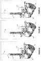
disc space 22 orsuperior vertebra 21 is achieved via a channel formed in inferior vertebra's 20pedicle 24.FIGS. 2A to 7D present apparatus for forming such a channel according to various example. In this example a normal channel is first formed in theinferior vertebrae 20's pedicle. Then a second, offset channel is formed in theinferior vertebrae 20 based on the formed normal channel. The second, offset channel may enable access thedisc space 22 orsuperior vertebrae 21. - 046
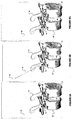
FIG. 2A is a simplified coronal view,FIG. 2B is a simplified sagittal view,FIG. 2C is a simplified posterior view, andFIG. 2D is an isometric view of thevertebrae pair wire 30 andsupport sleeve 32 according to various examples. In this example, theguide pin 30 is inserted at a posterior, lateral angle from the coronal view and normal to thevertebrae 20 from the sagittal view. The guide pin extends into thevertebrae 20pedicle 24 while not violating the pedicle wall. In addition in an example asupport sleeve 32 may be inserted over theguide pin 30. Thesupport sleeve 32 may be a thin walled cannula in an example of the present invention. - 047
FIG. 3A is a simplified isometric view of thevertebrae pair FIG. 2D further including anobturator 36 andcannula 34 inserted over theguide pin 30 andsupport sleeve 32. In an theobturator 36 may be advanced toward apedicle 24 to create a tissue pathway to thepedicle 24.FIG. 3B is a simplified isometric view of thevertebrae pair obturator 36 and guidesleeve 32 have been removed leaving theguide pin 30 inserted into the pedicle with thecannula 34 over theguide pin 30.FIG. 3C is a simplified isometric view of thevertebrae pair FIG. 3B further including a cannulatedreamer 38 inserted over theguide pin 30 and within thecannula 34. In an example, thereamer 38 may be operatively advanced into thepedicle 24 to form a bore in thepedicle 24. In an example thereamer 38 may have about a 5mm diameter and about an 8mm depth stop. In this example, thereamer 38 may be used to form an approximately 10mm deep, 5mm in diameter bore (39 shown inFIG. 4A ) in thepedicle 24, the bore 39 axis being approximately normal to the coronal plane ofvertebrae 20. In this example thecannula 34 may have a diameter of about 8.5mm. - 048
FIG. 4A is a simplified isometric view of thevertebrae pair reamer 38 and thecannula 34 have been removed leaving theguide pin 30 inserted in the bored pedicle according to various examples.FIG. 4B is a simplified isometric view of thevertebrae pair FIG. 4A further including a cannulated spot facer 42 inserted over theguide pin 30. In an example, the spot facer 42 may be operatively advanced into thepedicle 24 to enlarge an upper section of the bore 39 formed in thepedicle 24. In an example the spot facer 42 has about a 12mm diameter with a projected wall. In an example the spot facer 42 forms a larger upper bore section to be occupied by a polyaxial or monoaxial pedicle receiving section, the section moveably coupled or couplable to a pedicle screw head. - 049
FIG. 4C is a simplified isometric view of thevertebrae pair guide pin 30 inserted in the enlarged, bored pedicle according to various examples.FIG. 4D is a simplified isometric view of thevertebrae pair FIG. 4C further including a slottedcannula 46 inserted over theguide pin 30, thecannula 46 being advanced into the pedicle bore 44 in thepedicle 24 according to various examples.FIG. 5A is a simplified sagittal view of thevertebrae pair FIG. 4D further including a transpedicularchannel alignment tool 50 inserted over the cannula according to various examples. In an example thealignment tool 50 is aligned along the caudal-cephalad (sagittal plane). Thetool 50 includes anormal port 54 and an offsetport 52. The normal port is sized to receive theguide pin 30 or slottedcannula 46. - 050
FIG. 5B is a simplified sagittal view of thevertebrae pair guide pin 30 has been removed leaving the slottedcannula 46 inserted in pedicle bore 44 and transpedicularchannel alignment tool 50 inserted over thecannula 46 according to various embodiments. In this embodiment the alignment tool's 50normal port 54 is sized to receive the slottedcannula 46. In an embodiment the offsetport 52 is oriented an angle to thenormal port 54 about 20 degrees.FIG. 5C is a simplified sagittal view of thevertebrae pair FIG. 5B further including an offsetguide pin 56 with offsetsupport sleeve 58 inserted through the transpedicular channel alignment tool's 50 offsetguide port 52. In an embodiment the offsetguide pin 56 is advanced at the offset angle from normal to thevertebrae pair guide pin 56 is proceeding along a desired pathway in thepedicle 24 prior to advancement into thedisc space 22. - 051
FIG. 5D is a simplified sagittal view of thevertebrae pair FIG. 5C where thecannula 46 in the transpedicular channel alignment tool'snormal guide port 54 has been removed leaving the guide pin and support sleeve inserted through the transpedicular channel alignment tool's 50 offsetguide port 52 and the offsetguide pin 56 advanced at the offset angle according to various embodiments.FIG. 6A is a simplified sagittal view of thevertebrae pair FIG. 5D where the offsetsupport sleeve 58 in the transpedicular channel alignment tool's 50 offsetguide port 52 and thealignment tool 50 have been removed leaving the offsetguide pin 56 inserted through a transpedicular channel to thedisc space 22 according to various embodiments. As shown, theguide pin 56tip 57 is projecting into thedisc space 22. In an embodiment the transpedicular channel may be enlarged to enable different procedures to be performed in thedisc space 22. The transpedicular channel is not adjacent or near any nerve pathways in an embodiment, reducing the risk of nerve related injuries due a procedure being performed in thedisc space 22. - 052
FIG. 6B is a simplified sagittal view of thevertebrae pair FIG. 6A further including a cannulated reamer 62 within acannula 64 inserted over the offsetguide pin 56. In an example the reamer 62 may be operatively advanced into disc space via the transpedicular channel to enlarge thechannel 66. In an example the reamer 62 may be about a 5.5mm reamer to form a 5.5mm diameter channel 66 from thepedicle 24 of theinferior vertebra 20 to thedisc space 22.FIG. 6C is a simplified sagittal view of thevertebrae pair FIG. 6B where the cannulated reamer 62 and thecannula 64 have been removed leaving theguide pin 56 inserted through theenlarged transpedicular channel 66 to thedisc space 22. - 053
FIG. 6D is a simplified sagittal view of the vertebrae pair shown inFIG. 6C further including a slottedcannula 68 and obturator 67 inserted over the offsetguide pin 56. In an example a tapered obturator 67 within a slotted, thinwalled cannula 68 are inserted over the offsetguide pin 56 into thedisc space 22 via the transpedicular channel. In an example the slottedcannula 68 has about a 5.5mm diameter to be accommodated by thechannel 66 formed by the reamer 62.FIG. 6E is a simplified sagittal view of thevertebrae pair FIG. 6D where theguide pin 56 and obturator 67 have been removed leaving the slotted, offsetcannula 68 in theenlarged transpedicular channel 66 to thedisc space 22 according to various examples. Various tools and instruments may be employed via thecannula 68 to perform procedures within thedisc space 22 including discectomy, annulus closure or repair, fusion implantation including implants, bone growth materials, and allograft material. For example,FIG. 6F is a simplified sagittal view of the vertebrae pair shown inFIG. 6B where bone granules 63 (allograft material) packed with apowered material 65 have been inserted into thedisc space 22 via thecannula 68 according to various examples. - 054
FIGs. 6G and 6I depict theforce vectors 61 as applied to the compacted granular-poweredmaterial cannula 68 anddisc space 22. Thebone granules 63 may be packed with apowered material 65 to facilitate their passage into thedisc space 22 via thecannula 68. In particular thepowered material 65 helps prevent thelarger particles 63 from binding together and becoming wedged within acannula 68 as passed there-through. As shown inFIG. 6G theforce vectors 61 may split at the cannula distal end as thepowered material 65 andgranules 63 become disassociated as thecannula 68 walls prevent earlier such disassociation. - 055 In an example the powered material may be calcium sulfate, Plaster of Paris (calcium sulfate hemi-hydrate), finely pulverized cortical bone with decalcification, or similar fine material safe for insertion into the
disc space 22 and possible absorption. In an example thegranules 63 may be a granular cortical or structural allograft material. Thegranules 63 may have a generally spherical geometry and maximum cross sectional area smaller than the cross section area of adelivery cannula 68. In an example a binding agent may be employed to bind thepowered material 65 andgranules 65 including evaporated or saturated sugar or starch solution. The granular composite (65 and 63 and binding agent) may be fashioned into cylindrical pellets using a thermal and pressure modulated curing process. The resultant pellets may then be sterilely packaged. - 056 In an example the cylindrical pellets may be packaged within a thin walled polymer material, e.g. "straws". Such packages (pellets with straws) may be inserted into a
delivery cannula 68 or alternatively placed in automated delivery devices or systems. Such cylindrical pellets may be driven vialinear forces 61 through the length of thecannula 68, without pellet dissociation or granular element binding. As noted once the composite (63, 65) exits thesupportive cannula 68 walls additional forces (e.g. impact loading uponvertebra disc annulus 22 may dissociate thegranules 63. Such dissociation may form an expanding sphere of composite material, the sphere capable of effecting bone displacement or fracture site reduction and having load bearing capacity proportional to the material 63 density. The powered material 61-granules 65 composition may be used in cannulated procedures for intervertebral disc arthrodesis, vertebroplasty applications for vertebral compression fractures, periarticular depression fracture reductions and bone grafting, bone cyst therapies, etc. - 057 Referring to
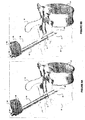
FIG. 5C thealignment tool 50 may create an offset angle of about 20 degrees of normal that may be used to form a transpedicular pathway or channel to a disc space via aninferior vertebra 20. In another embodiment it may be desirable to access the lower endplate of thesuperior vertebra 21 in addition to thedisc space 22.FIG. 7A is a simplified isometric view of thevertebrae pair FIG. 4D further including an offsetguide pin 56 withsupport sleeve 58 and second transpedicularchannel alignment tool 90. In this embodiment thesecond alignment tool 90 creates an offset angle of about 35 degrees relative to thenormal port 92. In this embodiment the offsetguide pin 56 andsupport sleeve 58 are inserted through the second transpedicular channel alignment tool's 90 offsetguide port 94. The greater offset angle provided by thesecond alignment tool 90 may enable the guide pin to be advanced through thedisc space 22 and into thelower endplate 23 of the superior vertebra 21 (seeFIG. 7D ) according to various embodiments.FIG. 7B is a simplified sagittal view of thevertebrae pair FIG. 7A showing that the second offset angle from normal is greater than the offset angle show inFIGS. 5A to 5D according to various embodiments. - 058
FIG. 7C is a simplified sagittal view of thevertebrae pair FIG. 7B where thecannula 46 in the second transpedicular channel alignment tool's 90normal guide port 92 has been removed leaving the offsetguide pin 56 andsupport sleeve 58 inserted through the transpedicular channel alignment tool's offsetguide port 94. The offsetguide pin 56tip 57 has been inserted into thedisc space 22.FIG. 7D is a simplified sagittal view of thevertebrae pair FIG. 7C where the offsetsupport sleeve 58 in the second transpedicular channel alignment tool's offsetguide port 94 and thesecond alignment tool 90 have been removed leaving theguide pin 56 inserted through a transpedicular channel to thedisc space 22 according to various embodiments. As described above in the formation of thetranspedicular channel 66, a cannulated reamer 62 within a sleeve may be provided to create an enlarged pathway through thedisc space 22 and into theendplate 23. Then a thin walled, slottedcannula 68 and obturator 67 pair may inserted over theguide pin 56 and theguide pin 56 and obturator 67 removed leaving the slottedcannula 68 extending theendplate 23. - 059 Via the second transpedicular channel procedures may be performed with the disc space and into the
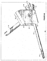
superior vertebra 21. For example,FIG. 7E is a simplified sagittal view of thevertebrae pair distraction screw 70 advanced over the offset guide pin orwire 56 through the disc space into the superior vertebra via a second transpedicular channel according to various embodiments. The compression-distraction screw 70 has distal thread 72, proximal thread 74, non-threaded central section 76, and lockingports 78. In an embodiment, the distal thread 72 can be independently rotated via a head within the central section 76. In addition, in an embodiment the distal threaded portion 72 may have a sleeve within the central section 76 so the portion 72 may extend away or toward the portion 74. - 060 In another embodiment other instrumentation may inserted into the
superior vertebra 21 via the transpedicular channel.FIG. 7F is a simplified sagittal view of thevertebrae pair fusion construct 80 advanced through theinferior vertebra 20 anddisc space 22 into thesuperior vertebra 23 via the second transpedicular channel according to various embodiments. In this embodiment theconstruct 80 is a bone dowel having a proximal 84 anddistal end 82. The bone dowel's 80distal end 82 may be embedded into thesuperior vertebra 21endplate 23 and itsproximal end 84 in the inferior vertebra. In an embodiment a portion of thedisc 22 may be removed and replaced with implants, bone growth materials, or allograft material prior to the fusion construct 80 insertion/implantation. The transpedicular channel into thesuperior vertebra 21 may also be used to perform kyphoplasty and other vertebra height restoration and modification procedures. - 061 After performing one ore more procedures via the transpedicular channel, it may be desirable to access the
normal pedicle channel 44 to perform one or more procedures via thenormal pedicle channel 44, e.g., insertion of a pedicle screw as part fixation instrumentation.FIG. 8A is a simplified isometric view of the vertebrae pair shown inFIG. 6D including a reversepedicle alignment tool 80 inserted over the offsetcannula 68 according to various embodiments. The reversepedicle alignment tool 80 includes an offsetguide port 82 and anormal guide port 84. The offsetguide port 82 is sized to fit the offsetcannula 68.FIG. 8B is a simplified isometric view of the vertebrae pair shown inFIG. 8A including theguide pin 30 inserted in the reverse alignment tool's 80normal guide port 84. In an embodiment theguide pin 30 passes through thecannula 68slot 69. - 062
FIG. 8C is a simplified isometric view of thevertebrae pair FIG. 8B where the offsetcannula 68 has been removed and theguide pin 30 has been advanced into the pediclenormal channel 45 according to various embodiments.FIG. 8D is a simplified isometric view,FIG. 8E is a simplified sagittal view, andFIG. 8F is a simplified coronal view of thevertebrae pair FIG. 8C where the reversepedicle alignment tool 80 has been removed leaving theguide pin 30 in thechannel 45 according to various embodiments. Theguide pin 30 may then be used to access thenormal pedicle channel 45 to perform one or more procedures via thenormal pedicle channel 45, e.g., insertion of a pedicle screw as part fixation instrumentation. - 063
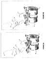
FIGS. 9A to 9F are diagrams of another transpedicular channel alignment andaccess tool system 200 according toclaim 1. As shown in these FIGs., thesystem 200 may include a length or extension adjustable, slotted 216,cannula 210, a cannula offsettool 220, ahandle 230, and an extension orlength adjustment knob 240 for thecannula 210. Thehandle 230 may transversely (relative to cannula 10) engage the offsettool 220 via abore 228 and handleextension 232. - 064 The offset
tool 220 may include afirst cannula channel 223 forcannula 210, asecond channel 222 for a cannula or guide wire, a guidewire release slot 224, and aflange 228 for engaging one ormore tabs 242 of theknob 240. As shown inFIG. 9B thehandle 230 may include a larger, distal section 234. Thechannel 224 andcannula 210slot 216 may be conFIG.d so a guide wire or other tool inserted into thechannel 224 may pass through thecannula 210 via theslot 216. Thesystem 200 may include a set pin or screw 229 in the offsettool 220 to fixably position thecannula 210 extension. As shown inFIG. 9C thesystem 200 may also include a set pin or screw 227 in the offsettool 220 to releasably engage thehandle 230 so thehandle extension 232 may be removed from thetool 220channel 228.FIG. 9F includes a partial cross sectional view of the offsettool 220 showing ariser 244 that may be coupled to theknob 240 to enable translation of thecannula 210slot 216. - 065
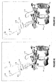
FIGS. 10A to 10F are diagrams of the transpedicular channel alignment andaccess tool system 200 employed in avertebra 20 according to various embodiments. Thecannula 210 may be inserted normally to thespinal vertebra 20 pedicle. Aguide wire 56 andcannula 58 may be placed with theslot 222 of thetool 200. Theguide wire 56 andcannula 58 may be inserted into thespinal vertebra 20,disc space 22, or adjacentspinal vertebra 21 as a function of thecannula 210slot 216 translation via the knob 40. In an embodiment thecannula 210 may have aguide wire 32 inserted therein to securely engage thecannula 210 in thespinal vertebra 20. Theguide wire 32 may be partially removed to enableguide wire 56 orcannula 58 to pass through thecannula 210slot 216 and into one of thespinal vertebra 20,disc space 22, and adjacentspinal vertebra 21. - 066 In an embodiment the
knob 240 may be rotate to linearly translate thecannula 210. Thecannula 210 translation may change the offset angle between thechannel 222 andcannula 210. The offset betweenchannel 222 andcannula 210 may enable aguide wire 58 orcannula 56 to engage thevertebra 20 whenknob 240 is rotated to a first point. The offset betweenchannel 222 andcannula 210 may enable aguide wire 58 orcannula 56 to engage thedisc space 22 whenknob 240 is rotated to a second point. The offset betweenchannel 222 andcannula 210 may enable aguide wire 58 orcannula 56 to engage theadjacent vertebra 21 whenknob 240 is rotated to a third point. - 067 While this invention has been described in terms of a best mode for achieving the objectives of the invention, it will be appreciated by those skilled in the art that variations may be accomplished in view of these teachings without deviating from scope of the present invention. For example, the
inferior vertebrae 20 may be the sacrum and thesuperior vertebrae 21 the adjacent vertebrae, L5 in humans.
Claims (6)
- A system characterised by, including:an offset guide (220), the guide including a first channel (223) with a first longitudinal axis, wherein the first channel (223) has a port located on a first outside edge of the offset guide (220) and extends to a second, opposite edge of the offset guide (220); anda second channel (222) with a second longitudinal axis, wherein the second channel (222) has a port on the first outside edge of the offset guide (220) located a fixed distance away from the port of the first channel (223) and extends to the second, opposite edge of the offset guide (220), wherein the first longitudinal axis is offset a predetermined angle from the second longitudinal axis; anda cannula (210) extending through the port of the first channel (223) on the first outside edge along the first longitudinal axis, comprising:a proximal end engaged with the offset guide (220);a distal end comprising a slot (216) that is co-planar with the first longitudinal axis, wherein the slot (216) extends a length from the distal end of the cannula (210) to a region proximal of the distal end; anda length extending between the proximal end and the distal end;wherein the first longitudinal axis intersects with the second longitudinal axis within the slot (216) and at an entry to a transpedicular channel.
- The system of claim 1, further comprising a rotatable knob (240) configured to be rotated such that the cannula (210) is linearly translated along the first longitudinal axis within the first channel (223) of the offset guide (220).
- The system of claim 1, further comprising a guide wire (56) extending through the second channel (222) along the second longitudinal axis and having a length configured to pass through the slot (216) of the cannula (210).
- The system of claim 3, wherein the guide wire (56) is constrained by a second cannula (58) engaged at a proximal end to the offset guide (220).
- The system of claim 4, wherein the second cannula (58) extends along the second longitudinal axis and terminates within an intervertebral disc space.
- The system of claim 4, wherein the second cannula (58) extends along the second longitudinal axis and terminates within an adjacent vertebra.
Applications Claiming Priority (3)
| Application Number | Priority Date | Filing Date | Title |
|---|---|---|---|
| US73927405P | 2005-11-23 | 2005-11-23 | |
| US84748006P | 2006-09-26 | 2006-09-26 | |
| PCT/US2006/045224 WO2007062132A2 (en) | 2005-11-23 | 2006-11-22 | Percutaneous transpedicular access, fusion, discectomy, and stabilization system and method |
Publications (3)
| Publication Number | Publication Date |
|---|---|
| EP1951159A2 EP1951159A2 (en) | 2008-08-06 |
| EP1951159A4 EP1951159A4 (en) | 2012-04-25 |
| EP1951159B1 true EP1951159B1 (en) | 2015-08-19 |
Family
ID=38067904
Family Applications (1)
| Application Number | Title | Priority Date | Filing Date |
|---|---|---|---|
| EP06838283.7A Active EP1951159B1 (en) | 2005-11-23 | 2006-11-22 | Percutaneous transpedicular access, fusion, discectomy, and stabilization system |
Country Status (5)
| Country | Link |
|---|---|
| US (2) | US7963970B2 (en) |
| EP (1) | EP1951159B1 (en) |
| JP (1) | JP5160438B2 (en) |
| CA (1) | CA2628962C (en) |
| WO (1) | WO2007062132A2 (en) |
Families Citing this family (69)
| Publication number | Priority date | Publication date | Assignee | Title |
|---|---|---|---|---|
| US20030055316A1 (en) * | 2001-09-19 | 2003-03-20 | Brannon James Kevin | Endoscopic bone debridement |
| US7803188B2 (en) * | 2002-08-27 | 2010-09-28 | Warsaw Orthopedic, Inc. | Systems and methods for intravertebral reduction |
| WO2006034436A2 (en) | 2004-09-21 | 2006-03-30 | Stout Medical Group, L.P. | Expandable support device and method of use |
| US7887538B2 (en) | 2005-10-15 | 2011-02-15 | Baxano, Inc. | Methods and apparatus for tissue modification |
| US9101386B2 (en) | 2004-10-15 | 2015-08-11 | Amendia, Inc. | Devices and methods for treating tissue |
| US7857813B2 (en) | 2006-08-29 | 2010-12-28 | Baxano, Inc. | Tissue access guidewire system and method |
| US9247952B2 (en) | 2004-10-15 | 2016-02-02 | Amendia, Inc. | Devices and methods for tissue access |
| US8048080B2 (en) | 2004-10-15 | 2011-11-01 | Baxano, Inc. | Flexible tissue rasp |
| US20110190772A1 (en) | 2004-10-15 | 2011-08-04 | Vahid Saadat | Powered tissue modification devices and methods |
| US8221397B2 (en) | 2004-10-15 | 2012-07-17 | Baxano, Inc. | Devices and methods for tissue modification |
| US8430881B2 (en) | 2004-10-15 | 2013-04-30 | Baxano, Inc. | Mechanical tissue modification devices and methods |
| US8062300B2 (en) | 2006-05-04 | 2011-11-22 | Baxano, Inc. | Tissue removal with at least partially flexible devices |
| US7578819B2 (en) | 2005-05-16 | 2009-08-25 | Baxano, Inc. | Spinal access and neural localization |
| US8257356B2 (en) | 2004-10-15 | 2012-09-04 | Baxano, Inc. | Guidewire exchange systems to treat spinal stenosis |
| US20100331883A1 (en) | 2004-10-15 | 2010-12-30 | Schmitz Gregory P | Access and tissue modification systems and methods |
| US20110004207A1 (en) | 2004-10-15 | 2011-01-06 | Baxano, Inc. | Flexible Neural Localization Devices and Methods |
| US7938830B2 (en) | 2004-10-15 | 2011-05-10 | Baxano, Inc. | Powered tissue modification devices and methods |
| US7918849B2 (en) | 2004-10-15 | 2011-04-05 | Baxano, Inc. | Devices and methods for tissue access |
| US8617163B2 (en) | 2004-10-15 | 2013-12-31 | Baxano Surgical, Inc. | Methods, systems and devices for carpal tunnel release |
| CA2614898C (en) | 2005-04-27 | 2014-04-22 | Trinity Orthopedics, Llc | Mono-planar pedilcle screw method, system, and kit |
| US8366712B2 (en) | 2005-10-15 | 2013-02-05 | Baxano, Inc. | Multiple pathways for spinal nerve root decompression from a single access point |
| US8062298B2 (en) | 2005-10-15 | 2011-11-22 | Baxano, Inc. | Flexible tissue removal devices and methods |
| US8092456B2 (en) | 2005-10-15 | 2012-01-10 | Baxano, Inc. | Multiple pathways for spinal nerve root decompression from a single access point |
| US7963970B2 (en) | 2005-11-23 | 2011-06-21 | Trinity Orthopedics | Percutaneous transpedicular access, fusion, discectomy, and stabilization system and method |
| EP1983938A4 (en) * | 2006-02-02 | 2012-07-25 | Trinity Orthopedics | Percutaneous facet joint fusion system and method |
| JP5542273B2 (en) | 2006-05-01 | 2014-07-09 | スタウト メディカル グループ,エル.ピー. | Expandable support device and method of use |
| EP2194861A1 (en) | 2007-09-06 | 2010-06-16 | Baxano, Inc. | Method, system and apparatus for neural localization |
| EP2923664B1 (en) * | 2007-10-17 | 2019-01-02 | ARO Medical ApS | Systems and apparatuses for torsional stabilisation |
| US8192436B2 (en) | 2007-12-07 | 2012-06-05 | Baxano, Inc. | Tissue modification devices |
| US20090222011A1 (en) * | 2008-02-28 | 2009-09-03 | Warsaw Orthopedic, Inc. | Targeting surgical instrument for use in spinal disc replacement and methods for use in spinal disc replacement |
| WO2009111480A2 (en) * | 2008-03-03 | 2009-09-11 | Trinity Orthopedics, Llc | Spool intervertebral distraction device and method |
| US20090312764A1 (en) * | 2008-06-11 | 2009-12-17 | Marino James F | Intraosseous transpedicular methods and devices |
| US9314253B2 (en) | 2008-07-01 | 2016-04-19 | Amendia, Inc. | Tissue modification devices and methods |
| US8398641B2 (en) | 2008-07-01 | 2013-03-19 | Baxano, Inc. | Tissue modification devices and methods |
| US8409206B2 (en) | 2008-07-01 | 2013-04-02 | Baxano, Inc. | Tissue modification devices and methods |
| EP2328489B1 (en) | 2008-07-14 | 2019-10-09 | Amendia, Inc. | Tissue modification devices |
| US20100211176A1 (en) | 2008-11-12 | 2010-08-19 | Stout Medical Group, L.P. | Fixation device and method |
| US20100204795A1 (en) | 2008-11-12 | 2010-08-12 | Stout Medical Group, L.P. | Fixation device and method |
| US8864773B2 (en) * | 2009-01-14 | 2014-10-21 | Globus Medical, Inc. | Devices and methods for treating vertebral fractures |
| US8439925B2 (en) * | 2009-05-11 | 2013-05-14 | Trinity Orthopedics, Llc | Transiliac-transsacral method of performing lumbar spinal interventions |
| KR20120047231A (en) * | 2009-06-17 | 2012-05-11 | 트리니티 올쏘피딕스, 엘엘씨 | Expanding intervertebral device and methods of use |
| US8394102B2 (en) | 2009-06-25 | 2013-03-12 | Baxano, Inc. | Surgical tools for treatment of spinal stenosis |
| US20110112586A1 (en) * | 2009-11-11 | 2011-05-12 | Jeffrey Allen Guyer | Methods and devices for portal fixation to the spine |
| US9333090B2 (en) | 2010-01-13 | 2016-05-10 | Jcbd, Llc | Systems for and methods of fusing a sacroiliac joint |
| US9381045B2 (en) | 2010-01-13 | 2016-07-05 | Jcbd, Llc | Sacroiliac joint implant and sacroiliac joint instrument for fusing a sacroiliac joint |
| US9421109B2 (en) | 2010-01-13 | 2016-08-23 | Jcbd, Llc | Systems and methods of fusing a sacroiliac joint |
| EP2523633B1 (en) * | 2010-01-13 | 2016-12-21 | Jcbd, Llc | Sacroiliac joint fixation fusion system |
| WO2014015309A1 (en) | 2012-07-20 | 2014-01-23 | Jcbd, Llc | Orthopedic anchoring system and methods |
| WO2012027490A2 (en) | 2010-08-24 | 2012-03-01 | Stout Medical Group, L.P. | Support device and method for use |
| US9149286B1 (en) * | 2010-11-12 | 2015-10-06 | Flexmedex, LLC | Guidance tool and method for use |
| EP2685921B1 (en) * | 2011-03-18 | 2019-03-13 | Raed M. Ali, M.D., Inc. | Transpedicular access to intervertebral spaces and related spinal fusion systems and methods |
| US9265620B2 (en) | 2011-03-18 | 2016-02-23 | Raed M. Ali, M.D., Inc. | Devices and methods for transpedicular stabilization of the spine |
| EP2720628B1 (en) | 2011-06-17 | 2021-08-11 | Jcbd, Llc | Sacroiliac joint implant system |
| CN103930058A (en) | 2011-08-23 | 2014-07-16 | 弗雷科斯米德克斯有限公司 | Tissue removal device and method |
| EP3011918B1 (en) | 2011-12-03 | 2018-07-25 | DePuy Synthes Products, Inc. | Safe cutting heads and systems for fast removal of a target tissue |
| US10687962B2 (en) | 2013-03-14 | 2020-06-23 | Raed M. Ali, M.D., Inc. | Interbody fusion devices, systems and methods |
| KR20160010862A (en) | 2013-03-14 | 2016-01-28 | 라에드 엠. 알리, 엠.디., 인크. | Lateral interbody fusion devices, systems and methods |
| US9826986B2 (en) | 2013-07-30 | 2017-11-28 | Jcbd, Llc | Systems for and methods of preparing a sacroiliac joint for fusion |
| US10245087B2 (en) | 2013-03-15 | 2019-04-02 | Jcbd, Llc | Systems and methods for fusing a sacroiliac joint and anchoring an orthopedic appliance |
| US9717539B2 (en) | 2013-07-30 | 2017-08-01 | Jcbd, Llc | Implants, systems, and methods for fusing a sacroiliac joint |
| EP3021768B1 (en) | 2013-07-19 | 2020-08-19 | DePuy Synthes Products, Inc. | An anti-clogging device for a vacuum-assisted, tissue removal system |
| WO2015017593A1 (en) | 2013-07-30 | 2015-02-05 | Jcbd, Llc | Systems for and methods of fusing a sacroiliac joint |
| US9980715B2 (en) | 2014-02-05 | 2018-05-29 | Trinity Orthopedics, Llc | Anchor devices and methods of use |
| US9801546B2 (en) | 2014-05-27 | 2017-10-31 | Jcbd, Llc | Systems for and methods of diagnosing and treating a sacroiliac joint disorder |
| US9962171B2 (en) * | 2015-06-09 | 2018-05-08 | Warsaw Orthopedic, Inc. | Surgical instrument and method |
| US20170209188A1 (en) * | 2016-01-26 | 2017-07-27 | Gerald Schell | Rodless bivertebral transpedicular fixation with interbody fusion |
| US10966773B2 (en) | 2017-07-31 | 2021-04-06 | DePuy Synthes Products, Inc. | Correction guide for femoral neck |
| US10603055B2 (en) | 2017-09-15 | 2020-03-31 | Jcbd, Llc | Systems for and methods of preparing and fusing a sacroiliac joint |
| US11690974B2 (en) | 2019-04-25 | 2023-07-04 | Warsaw Orthopedic, Inc. | Methods and devices for delivering therapeutic materials to the intervertebral disc |
Family Cites Families (31)
| Publication number | Priority date | Publication date | Assignee | Title |
|---|---|---|---|---|
| GB8501907D0 (en) * | 1985-01-25 | 1985-02-27 | Thackray C F Ltd | Surgical instruments |
| JPH034845A (en) * | 1989-05-31 | 1991-01-10 | Olympus Optical Co Ltd | Insertion supporter |
| US5395317A (en) * | 1991-10-30 | 1995-03-07 | Smith & Nephew Dyonics, Inc. | Unilateral biportal percutaneous surgical procedure |
| US5762629A (en) * | 1991-10-30 | 1998-06-09 | Smith & Nephew, Inc. | Oval cannula assembly and method of use |
| US5242444A (en) * | 1991-11-04 | 1993-09-07 | University Of Florida | Lumbosacral fixation and fusion method and device |
| US5171279A (en) | 1992-03-17 | 1992-12-15 | Danek Medical | Method for subcutaneous suprafascial pedicular internal fixation |
| US5324295A (en) * | 1992-04-24 | 1994-06-28 | Shapiro Michael R | Drill guide for surgical pins |
| US5423826A (en) * | 1993-02-05 | 1995-06-13 | Danek Medical, Inc. | Anterior cervical plate holder/drill guide and method of use |
| US5334205A (en) * | 1993-06-30 | 1994-08-02 | The United States Of America As Represented By The Secretary Of The Air Force | Sacroiliac joint fixation guide |
| NZ272994A (en) | 1995-09-12 | 2001-06-29 | C G Surgical Ltd | Spinal prosthesis device which stabilises lamina after laminoplasty |
| DE29703947U1 (en) * | 1996-03-12 | 1997-06-05 | Plus Endoprothetik Ag | Device for percutaneous joint screwing |
| AU746955B2 (en) * | 1998-03-27 | 2002-05-09 | Cook Urological Inc. | Minimally-invasive medical retrieval device |
| JP2002537014A (en) | 1998-06-09 | 2002-11-05 | ヌバシブ, インコーポレイテッド | The iliac approach to enter the patient's intervertebral space |
| US6224603B1 (en) | 1998-06-09 | 2001-05-01 | Nuvasive, Inc. | Transiliac approach to entering a patient's intervertebral space |
| AU4246000A (en) | 1999-04-16 | 2000-11-02 | Nuvasive, Inc. | Articulation systems for positioning minimally invasive surgical tools |
| US6821276B2 (en) * | 1999-08-18 | 2004-11-23 | Intrinsic Therapeutics, Inc. | Intervertebral diagnostic and manipulation device |
| US6520967B1 (en) | 1999-10-20 | 2003-02-18 | Cauthen Research Group, Inc. | Spinal implant insertion instrument for spinal interbody prostheses |
| US6575899B1 (en) | 1999-10-20 | 2003-06-10 | Sdgi Holdings, Inc. | Methods and instruments for endoscopic interbody surgical techniques |
| US7615076B2 (en) * | 1999-10-20 | 2009-11-10 | Anulex Technologies, Inc. | Method and apparatus for the treatment of the intervertebral disc annulus |
| AU2726701A (en) | 1999-12-10 | 2001-06-18 | Nuvasive, Inc. | Facet screw and bone allograft intervertebral support and fusion system |
| US20030191474A1 (en) | 2000-02-16 | 2003-10-09 | Cragg Andrew H. | Apparatus for performing a discectomy through a trans-sacral axial bore within the vertebrae of the spine |
| US6358254B1 (en) | 2000-09-11 | 2002-03-19 | D. Greg Anderson | Method and implant for expanding a spinal canal |
| US7166107B2 (en) | 2000-09-11 | 2007-01-23 | D. Greg Anderson | Percutaneous technique and implant for expanding the spinal canal |
| US20030212400A1 (en) | 2002-03-12 | 2003-11-13 | Aesculap Ag & Co. Kg | Methods for treating spinal stenosis by pedicle distraction |
| CN100518672C (en) * | 2002-11-08 | 2009-07-29 | 维特林克股份有限公司 | Transpedicular intervertebral disk access method and device |
| US20050125066A1 (en) | 2003-12-08 | 2005-06-09 | Innovative Spinal Technologies | Nucleus replacement securing device and method |
| US20050187556A1 (en) | 2004-02-25 | 2005-08-25 | Synecor, Llc | Universal percutaneous spinal access system |
| US7600915B2 (en) | 2004-12-01 | 2009-10-13 | Trinity Orthopedics, Llc | Imager based object positioner system and method |
| CA2614898C (en) | 2005-04-27 | 2014-04-22 | Trinity Orthopedics, Llc | Mono-planar pedilcle screw method, system, and kit |
| JP2009517992A (en) | 2005-11-23 | 2009-04-30 | トリニティ・オーソペディックス・リミテッド・ライアビリティ・カンパニー | Guidance system positioner method and system |
| US7963970B2 (en) | 2005-11-23 | 2011-06-21 | Trinity Orthopedics | Percutaneous transpedicular access, fusion, discectomy, and stabilization system and method |
-
2006
- 2006-11-22 US US11/562,939 patent/US7963970B2/en not_active Expired - Fee Related
- 2006-11-22 CA CA2628962A patent/CA2628962C/en not_active Expired - Fee Related
- 2006-11-22 EP EP06838283.7A patent/EP1951159B1/en active Active
- 2006-11-22 JP JP2008542442A patent/JP5160438B2/en not_active Expired - Fee Related
- 2006-11-22 WO PCT/US2006/045224 patent/WO2007062132A2/en active Application Filing
-
2011
- 2011-06-14 US US13/160,414 patent/US8777957B2/en active Active
Also Published As
| Publication number | Publication date |
|---|---|
| WO2007062132A3 (en) | 2009-04-16 |
| CA2628962A1 (en) | 2007-05-31 |
| JP5160438B2 (en) | 2013-03-13 |
| US7963970B2 (en) | 2011-06-21 |
| EP1951159A4 (en) | 2012-04-25 |
| US20070162044A1 (en) | 2007-07-12 |
| EP1951159A2 (en) | 2008-08-06 |
| CA2628962C (en) | 2014-05-27 |
| US8777957B2 (en) | 2014-07-15 |
| JP2009519733A (en) | 2009-05-21 |
| WO2007062132A2 (en) | 2007-05-31 |
| US20110245838A1 (en) | 2011-10-06 |
Similar Documents
| Publication | Publication Date | Title |
|---|---|---|
| EP1951159B1 (en) | Percutaneous transpedicular access, fusion, discectomy, and stabilization system | |
| US20090312764A1 (en) | Intraosseous transpedicular methods and devices | |
| US8157806B2 (en) | Apparatus and methods for vertebral augmentation | |
| US8439925B2 (en) | Transiliac-transsacral method of performing lumbar spinal interventions | |
| AU2014332461B2 (en) | Spinal implant system and method | |
| JP4383014B2 (en) | Surgical fenestrated screw and method | |
| US7749228B2 (en) | Articulatable apparatus for cutting bone | |
| US9050147B2 (en) | System and methods for minimally invasive spine surgery | |
| WO2008097216A2 (en) | Percutaneous facet joint fusion system and method | |
| US20090264941A1 (en) | Guide sleeve for accessing a vertebral body and related methods of use | |
| US20110245880A1 (en) | Spinal fixator and method of use thereof | |
| EP3203941B1 (en) | Bone scaffold improvements | |
| AU2006304244A1 (en) | Apparatus and methods for vertebral augmentation | |
| US9326777B2 (en) | Decorticating surgical instruments and guidance systems with tactile feedback | |
| Nath | Posterior Thoracic Implants | |
| Nath | Posterior Thoracic Spinal Implants | |
| NZ731593B2 (en) | Bone scaffold improvements |
Legal Events
| Date | Code | Title | Description |
|---|---|---|---|
| PUAI | Public reference made under article 153(3) epc to a published international application that has entered the european phase |
Free format text: ORIGINAL CODE: 0009012 |
|
| 17P | Request for examination filed |
Effective date: 20080527 |
|
| AK | Designated contracting states |
Kind code of ref document: A2 Designated state(s): AT BE BG CH CY CZ DE DK EE ES FI FR GB GR HU IE IS IT LI LT LU LV MC NL PL PT RO SE SI SK TR |
|
| AX | Request for extension of the european patent |
Extension state: AL BA HR MK RS |
|
| R17D | Deferred search report published (corrected) |
Effective date: 20090416 |
|
| RIC1 | Information provided on ipc code assigned before grant |
Ipc: A61B 17/60 20060101ALI20090615BHEP Ipc: A61B 17/58 20060101ALI20090615BHEP Ipc: A61F 2/30 20060101ALI20090615BHEP Ipc: A61F 2/00 20060101ALI20090615BHEP Ipc: A61B 17/56 20060101AFI20090615BHEP |
|
| REG | Reference to a national code |
Ref country code: DE Ref legal event code: R079 Ref document number: 602006046383 Country of ref document: DE Free format text: PREVIOUS MAIN CLASS: A61F0002300000 Ipc: A61B0017560000 |
|
| A4 | Supplementary search report drawn up and despatched |
Effective date: 20120322 |
|
| RIC1 | Information provided on ipc code assigned before grant |
Ipc: A61B 17/58 20060101ALI20120316BHEP Ipc: A61F 2/00 20060101ALI20120316BHEP Ipc: A61F 2/30 20060101ALI20120316BHEP Ipc: A61B 17/56 20060101AFI20120316BHEP Ipc: A61B 17/60 20060101ALI20120316BHEP |
|
| DAX | Request for extension of the european patent (deleted) | ||
| GRAP | Despatch of communication of intention to grant a patent |
Free format text: ORIGINAL CODE: EPIDOSNIGR1 |
|
| INTG | Intention to grant announced |
Effective date: 20150320 |
|
| GRAP | Despatch of communication of intention to grant a patent |
Free format text: ORIGINAL CODE: EPIDOSNIGR1 |
|
| INTG | Intention to grant announced |
Effective date: 20150520 |
|
| GRAS | Grant fee paid |
Free format text: ORIGINAL CODE: EPIDOSNIGR3 |
|
| GRAA | (expected) grant |
Free format text: ORIGINAL CODE: 0009210 |
|
| AK | Designated contracting states |
Kind code of ref document: B1 Designated state(s): AT BE BG CH CY CZ DE DK EE ES FI FR GB GR HU IE IS IT LI LT LU LV MC NL PL PT RO SE SI SK TR |
|
| REG | Reference to a national code |
Ref country code: GB Ref legal event code: FG4D |
|
| REG | Reference to a national code |
Ref country code: CH Ref legal event code: EP |
|
| REG | Reference to a national code |
Ref country code: IE Ref legal event code: FG4D |
|
| REG | Reference to a national code |
Ref country code: AT Ref legal event code: REF Ref document number: 743210 Country of ref document: AT Kind code of ref document: T Effective date: 20150915 |
|
| REG | Reference to a national code |
Ref country code: DE Ref legal event code: R096 Ref document number: 602006046383 Country of ref document: DE |
|
| REG | Reference to a national code |
Ref country code: FR Ref legal event code: PLFP Year of fee payment: 10 |
|
| REG | Reference to a national code |
Ref country code: AT Ref legal event code: MK05 Ref document number: 743210 Country of ref document: AT Kind code of ref document: T Effective date: 20150819 |
|
| REG | Reference to a national code |
Ref country code: LT Ref legal event code: MG4D |
|
| REG | Reference to a national code |
Ref country code: NL Ref legal event code: MP Effective date: 20150819 |
|
| PG25 | Lapsed in a contracting state [announced via postgrant information from national office to epo] |
Ref country code: GR Free format text: LAPSE BECAUSE OF FAILURE TO SUBMIT A TRANSLATION OF THE DESCRIPTION OR TO PAY THE FEE WITHIN THE PRESCRIBED TIME-LIMIT Effective date: 20151120 Ref country code: LV Free format text: LAPSE BECAUSE OF FAILURE TO SUBMIT A TRANSLATION OF THE DESCRIPTION OR TO PAY THE FEE WITHIN THE PRESCRIBED TIME-LIMIT Effective date: 20150819 Ref country code: FI Free format text: LAPSE BECAUSE OF FAILURE TO SUBMIT A TRANSLATION OF THE DESCRIPTION OR TO PAY THE FEE WITHIN THE PRESCRIBED TIME-LIMIT Effective date: 20150819 Ref country code: LT Free format text: LAPSE BECAUSE OF FAILURE TO SUBMIT A TRANSLATION OF THE DESCRIPTION OR TO PAY THE FEE WITHIN THE PRESCRIBED TIME-LIMIT Effective date: 20150819 |
|
| PGFP | Annual fee paid to national office [announced via postgrant information from national office to epo] |
Ref country code: DE Payment date: 20151127 Year of fee payment: 10 Ref country code: IE Payment date: 20151130 Year of fee payment: 10 Ref country code: GB Payment date: 20151127 Year of fee payment: 10 |
|
| PG25 | Lapsed in a contracting state [announced via postgrant information from national office to epo] |
Ref country code: IS Free format text: LAPSE BECAUSE OF FAILURE TO SUBMIT A TRANSLATION OF THE DESCRIPTION OR TO PAY THE FEE WITHIN THE PRESCRIBED TIME-LIMIT Effective date: 20151219 Ref country code: PL Free format text: LAPSE BECAUSE OF FAILURE TO SUBMIT A TRANSLATION OF THE DESCRIPTION OR TO PAY THE FEE WITHIN THE PRESCRIBED TIME-LIMIT Effective date: 20150819 Ref country code: SE Free format text: LAPSE BECAUSE OF FAILURE TO SUBMIT A TRANSLATION OF THE DESCRIPTION OR TO PAY THE FEE WITHIN THE PRESCRIBED TIME-LIMIT Effective date: 20150819 Ref country code: ES Free format text: LAPSE BECAUSE OF FAILURE TO SUBMIT A TRANSLATION OF THE DESCRIPTION OR TO PAY THE FEE WITHIN THE PRESCRIBED TIME-LIMIT Effective date: 20150819 Ref country code: AT Free format text: LAPSE BECAUSE OF FAILURE TO SUBMIT A TRANSLATION OF THE DESCRIPTION OR TO PAY THE FEE WITHIN THE PRESCRIBED TIME-LIMIT Effective date: 20150819 |
|
| PGFP | Annual fee paid to national office [announced via postgrant information from national office to epo] |
Ref country code: FR Payment date: 20151217 Year of fee payment: 10 |
|
| PG25 | Lapsed in a contracting state [announced via postgrant information from national office to epo] |
Ref country code: NL Free format text: LAPSE BECAUSE OF FAILURE TO SUBMIT A TRANSLATION OF THE DESCRIPTION OR TO PAY THE FEE WITHIN THE PRESCRIBED TIME-LIMIT Effective date: 20150819 |
|
| PG25 | Lapsed in a contracting state [announced via postgrant information from national office to epo] |
Ref country code: DK Free format text: LAPSE BECAUSE OF FAILURE TO SUBMIT A TRANSLATION OF THE DESCRIPTION OR TO PAY THE FEE WITHIN THE PRESCRIBED TIME-LIMIT Effective date: 20150819 Ref country code: SK Free format text: LAPSE BECAUSE OF FAILURE TO SUBMIT A TRANSLATION OF THE DESCRIPTION OR TO PAY THE FEE WITHIN THE PRESCRIBED TIME-LIMIT Effective date: 20150819 Ref country code: EE Free format text: LAPSE BECAUSE OF FAILURE TO SUBMIT A TRANSLATION OF THE DESCRIPTION OR TO PAY THE FEE WITHIN THE PRESCRIBED TIME-LIMIT Effective date: 20150819 Ref country code: CZ Free format text: LAPSE BECAUSE OF FAILURE TO SUBMIT A TRANSLATION OF THE DESCRIPTION OR TO PAY THE FEE WITHIN THE PRESCRIBED TIME-LIMIT Effective date: 20150819 |
|
| REG | Reference to a national code |
Ref country code: DE Ref legal event code: R097 Ref document number: 602006046383 Country of ref document: DE |
|
| PG25 | Lapsed in a contracting state [announced via postgrant information from national office to epo] |
Ref country code: RO Free format text: LAPSE BECAUSE OF FAILURE TO SUBMIT A TRANSLATION OF THE DESCRIPTION OR TO PAY THE FEE WITHIN THE PRESCRIBED TIME-LIMIT Effective date: 20150819 |
|
| PLBE | No opposition filed within time limit |
Free format text: ORIGINAL CODE: 0009261 |
|
| STAA | Information on the status of an ep patent application or granted ep patent |
Free format text: STATUS: NO OPPOSITION FILED WITHIN TIME LIMIT |
|
| PG25 | Lapsed in a contracting state [announced via postgrant information from national office to epo] |
Ref country code: MC Free format text: LAPSE BECAUSE OF FAILURE TO SUBMIT A TRANSLATION OF THE DESCRIPTION OR TO PAY THE FEE WITHIN THE PRESCRIBED TIME-LIMIT Effective date: 20150819 Ref country code: LU Free format text: LAPSE BECAUSE OF FAILURE TO SUBMIT A TRANSLATION OF THE DESCRIPTION OR TO PAY THE FEE WITHIN THE PRESCRIBED TIME-LIMIT Effective date: 20151122 |
|
| REG | Reference to a national code |
Ref country code: CH Ref legal event code: PL |
|
| 26N | No opposition filed |
Effective date: 20160520 |
|
| PG25 | Lapsed in a contracting state [announced via postgrant information from national office to epo] |
Ref country code: LI Free format text: LAPSE BECAUSE OF NON-PAYMENT OF DUE FEES Effective date: 20151130 Ref country code: CH Free format text: LAPSE BECAUSE OF NON-PAYMENT OF DUE FEES Effective date: 20151130 |
|
| PG25 | Lapsed in a contracting state [announced via postgrant information from national office to epo] |
Ref country code: SI Free format text: LAPSE BECAUSE OF FAILURE TO SUBMIT A TRANSLATION OF THE DESCRIPTION OR TO PAY THE FEE WITHIN THE PRESCRIBED TIME-LIMIT Effective date: 20150819 |
|
| PG25 | Lapsed in a contracting state [announced via postgrant information from national office to epo] |
Ref country code: BE Free format text: LAPSE BECAUSE OF FAILURE TO SUBMIT A TRANSLATION OF THE DESCRIPTION OR TO PAY THE FEE WITHIN THE PRESCRIBED TIME-LIMIT Effective date: 20150819 |
|
| PG25 | Lapsed in a contracting state [announced via postgrant information from national office to epo] |
Ref country code: IT Free format text: LAPSE BECAUSE OF NON-PAYMENT OF DUE FEES Effective date: 20151122 |
|
| PG25 | Lapsed in a contracting state [announced via postgrant information from national office to epo] |
Ref country code: HU Free format text: LAPSE BECAUSE OF FAILURE TO SUBMIT A TRANSLATION OF THE DESCRIPTION OR TO PAY THE FEE WITHIN THE PRESCRIBED TIME-LIMIT; INVALID AB INITIO Effective date: 20061122 Ref country code: BG Free format text: LAPSE BECAUSE OF FAILURE TO SUBMIT A TRANSLATION OF THE DESCRIPTION OR TO PAY THE FEE WITHIN THE PRESCRIBED TIME-LIMIT Effective date: 20150819 |
|
| REG | Reference to a national code |
Ref country code: DE Ref legal event code: R119 Ref document number: 602006046383 Country of ref document: DE |
|
| PG25 | Lapsed in a contracting state [announced via postgrant information from national office to epo] |
Ref country code: CY Free format text: LAPSE BECAUSE OF FAILURE TO SUBMIT A TRANSLATION OF THE DESCRIPTION OR TO PAY THE FEE WITHIN THE PRESCRIBED TIME-LIMIT Effective date: 20150819 |
|
| GBPC | Gb: european patent ceased through non-payment of renewal fee |
Effective date: 20161122 |
|
| REG | Reference to a national code |
Ref country code: IE Ref legal event code: MM4A |
|
| REG | Reference to a national code |
Ref country code: FR Ref legal event code: ST Effective date: 20170731 |
|
| PG25 | Lapsed in a contracting state [announced via postgrant information from national office to epo] |
Ref country code: IT Free format text: LAPSE BECAUSE OF NON-PAYMENT OF DUE FEES Effective date: 20151122 Ref country code: TR Free format text: LAPSE BECAUSE OF FAILURE TO SUBMIT A TRANSLATION OF THE DESCRIPTION OR TO PAY THE FEE WITHIN THE PRESCRIBED TIME-LIMIT Effective date: 20150819 |
|
| PGFP | Annual fee paid to national office [announced via postgrant information from national office to epo] |
Ref country code: IT Payment date: 20151222 Year of fee payment: 10 |
|
| PGRI | Patent reinstated in contracting state [announced from national office to epo] |
Ref country code: IT Effective date: 20170710 |
|
| PG25 | Lapsed in a contracting state [announced via postgrant information from national office to epo] |
Ref country code: FR Free format text: LAPSE BECAUSE OF NON-PAYMENT OF DUE FEES Effective date: 20161130 Ref country code: IT Free format text: LAPSE BECAUSE OF NON-PAYMENT OF DUE FEES Effective date: 20161122 |
|
| PGRI | Patent reinstated in contracting state [announced from national office to epo] |
Ref country code: IT Effective date: 20170710 |
|
| PG25 | Lapsed in a contracting state [announced via postgrant information from national office to epo] |
Ref country code: DE Free format text: LAPSE BECAUSE OF NON-PAYMENT OF DUE FEES Effective date: 20170601 Ref country code: GB Free format text: LAPSE BECAUSE OF NON-PAYMENT OF DUE FEES Effective date: 20161122 Ref country code: IE Free format text: LAPSE BECAUSE OF NON-PAYMENT OF DUE FEES Effective date: 20161122 |
|
| PG25 | Lapsed in a contracting state [announced via postgrant information from national office to epo] |
Ref country code: PT Free format text: LAPSE BECAUSE OF FAILURE TO SUBMIT A TRANSLATION OF THE DESCRIPTION OR TO PAY THE FEE WITHIN THE PRESCRIBED TIME-LIMIT Effective date: 20150819 |