EP1943862B1 - Ps handover support indication - Google Patents
Ps handover support indication Download PDFInfo
- Publication number
- EP1943862B1 EP1943862B1 EP06820837.0A EP06820837A EP1943862B1 EP 1943862 B1 EP1943862 B1 EP 1943862B1 EP 06820837 A EP06820837 A EP 06820837A EP 1943862 B1 EP1943862 B1 EP 1943862B1
- Authority
- EP
- European Patent Office
- Prior art keywords
- network controller
- radio network
- radio
- radio link
- cell
- Prior art date
- Legal status (The legal status is an assumption and is not a legal conclusion. Google has not performed a legal analysis and makes no representation as to the accuracy of the status listed.)
- Active
Links
- 238000000034 method Methods 0.000 claims description 28
- 238000005516 engineering process Methods 0.000 claims description 21
- 238000012546 transfer Methods 0.000 claims description 7
- 238000010295 mobile communication Methods 0.000 claims description 4
- 238000007792 addition Methods 0.000 description 20
- 230000011664 signaling Effects 0.000 description 13
- 238000002360 preparation method Methods 0.000 description 4
- 238000012545 processing Methods 0.000 description 3
- 238000004891 communication Methods 0.000 description 2
- 101150014328 RAN2 gene Proteins 0.000 description 1
- 101150074586 RAN3 gene Proteins 0.000 description 1
- 230000001413 cellular effect Effects 0.000 description 1
- 238000011161 development Methods 0.000 description 1
- 230000018109 developmental process Effects 0.000 description 1
- 238000007726 management method Methods 0.000 description 1
- 230000007704 transition Effects 0.000 description 1
Images


Classifications
-
- H—ELECTRICITY
- H04—ELECTRIC COMMUNICATION TECHNIQUE
- H04W—WIRELESS COMMUNICATION NETWORKS
- H04W36/00—Hand-off or reselection arrangements
- H04W36/0005—Control or signalling for completing the hand-off
- H04W36/0055—Transmission or use of information for re-establishing the radio link
- H04W36/0061—Transmission or use of information for re-establishing the radio link of neighbour cell information
-
- H—ELECTRICITY
- H04—ELECTRIC COMMUNICATION TECHNIQUE
- H04W—WIRELESS COMMUNICATION NETWORKS
- H04W36/00—Hand-off or reselection arrangements
- H04W36/0005—Control or signalling for completing the hand-off
- H04W36/0055—Transmission or use of information for re-establishing the radio link
- H04W36/0066—Transmission or use of information for re-establishing the radio link of control information between different types of networks in order to establish a new radio link in the target network
-
- H—ELECTRICITY
- H04—ELECTRIC COMMUNICATION TECHNIQUE
- H04W—WIRELESS COMMUNICATION NETWORKS
- H04W36/00—Hand-off or reselection arrangements
- H04W36/0005—Control or signalling for completing the hand-off
- H04W36/0011—Control or signalling for completing the hand-off for data sessions of end-to-end connection
- H04W36/0022—Control or signalling for completing the hand-off for data sessions of end-to-end connection for transferring data sessions between adjacent core network technologies
- H04W36/00222—Control or signalling for completing the hand-off for data sessions of end-to-end connection for transferring data sessions between adjacent core network technologies between different packet switched [PS] network technologies, e.g. transferring data sessions between LTE and WLAN or LTE and 5G
-
- H—ELECTRICITY
- H04—ELECTRIC COMMUNICATION TECHNIQUE
- H04W—WIRELESS COMMUNICATION NETWORKS
- H04W36/00—Hand-off or reselection arrangements
- H04W36/10—Reselecting an access point controller
-
- H—ELECTRICITY
- H04—ELECTRIC COMMUNICATION TECHNIQUE
- H04W—WIRELESS COMMUNICATION NETWORKS
- H04W36/00—Hand-off or reselection arrangements
- H04W36/14—Reselecting a network or an air interface
-
- H—ELECTRICITY
- H04—ELECTRIC COMMUNICATION TECHNIQUE
- H04W—WIRELESS COMMUNICATION NETWORKS
- H04W92/00—Interfaces specially adapted for wireless communication networks
- H04W92/16—Interfaces between hierarchically similar devices
- H04W92/22—Interfaces between hierarchically similar devices between access point controllers
Definitions
- the present invention relates to mobile communications and, more particularly, to signaling between radio network subsystems relating to handover decisions.
- Packet Switched (PS) Handover was defined in Release 6 of the relevant 3GPP documents (23.060, 43.129, 24.008, 44.064, 48.018, 25.331, 25.413) based on a GERAN study.
- Inter-RAT Inter-Radio Access Technology
- PS Handover between UMTS and GSM signalling had been added in RRC (Uu interface) and RANAP (Iu interface.) at RAN2 #48 (R2-052315) and RAN3 #48. (R3-050924) (28 August 05 - 03 September 05).
- the SRNC doesn't know whether the target BSS supports PS Handover or not and the SRNC just has to try.
- the SRNC decides to perform PS Handover toward a GERAN cell
- SRNC just has to initiate inter- RAT PS Handover and see whether it will receive a positive reply or not. If the PS Handover attempt fails, the SRNC and SGSN processing is wasted on account of the unnecessary message transfer and unnecessary relocation preparation. This problem can be solved easily ifRNC knows the target GERAN cell capability, i.e., whether it support PS Handover or not.
- This GERAN neighbor cell capability can be configured by O&M system or by some signalling in CRNC, i.e., if the O&M system provides information on GERAN neighbor cell capability to the Controlling RNC (CRNC).
- CRNC Controlling RNC
- this O&M solution also has a limitation in case the CRNC is not also the SRNC.
- the O&M system will configure the GERAN-Neighbour cell capability only in the DRNC.
- the SRNC is the one which decides whether PS Handover will start or not. In the current 3GPP Specifications, there is no means provided for the SRNC to know whether the target GERAN cell supports PS Handover or not.
- EP 1 503 606 discloses a radio resource management method (CRRM) that is performed in a mobile radio communication network employing different radio access technologies (UTRAN, GERAN) that overlap over a geographic area subdivided into cells belonging to the domains of respective controllers (RNC, BSC) which are connected to each other in overlapping or adjacent domains and to a core network (CN) by means of relevant interfaces (Iu, Iur, A, Gb).
- the controllers calculate new traffic-related Information Elements (IEs) to be exchanged over the existing interfaces to the aim of planning handovers and/or cell reselections towards adjacent cells either of the same or different RAT.
- IEs new traffic-related Information Elements
- WO 2005/027561 discloses a packet-switched handover from a first cell to a second cell in a cellular network.
- Packet-switched services are provided for a mobile station in the first cell based on a set of information relating to provision of packet-switched services and a protocol for handling provision of packet-switched services for mobile stations, said protocol being a protocol between a cell and a respective control network element.
- the present invention provides information such as by using one bit in the GERAN Cell Capacity IE to indicate whether a neighbor GERAN cell supports PS Handover or not in RNSAP (Specified in TS25.423).
- This GERAN Cell Capacity IE or similar maybe included in the Neighbor GSM Cell Information IE and transferred to the SRNC from the DRNC (CRNC) via a RADIO LINK SETUP RESPONSE message, a RADIO LINK SETUP FAILURE message, a RADIO LINK ADDITION RESPONSE message or a RADIO LINK ADDITION FAILURE message.
- the present invention provides methods, radio network controllers and systems according to the attached claims.
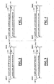
- Fig. 1 shows the operation of the present invention in an environment with both UMTS and GSM access with all cells on the UMTS side supporting both circuit switched and packet switched services handover but with only some cells on the GSM side supporting handover in packet switched domain.
- Fig. 2 shows a possible signaling procedure for a successful radio link setup using an information element modified according to the present invention.
- Fig. 3 shows a radio link setup procedure for an unsuccessful operation with the signaling information modified according to the present invention.
- Fig. 4 shows a radio link addition procedure with an information element provided according to the present invention for a successful operation.
- Fig. 5 shows a radio link addition procedure for an unsuccessful operation with information provided according to the present invention.
- Fig. 6 shows a prior art cell capability information element used to transfer the capabilities of a certain cell via the Iur interface, according to the prior art.
- Fig. 7 shows the cell capability information element modified, according to the present invention, to include information concerning the ability of a cell to handle a packet switched handover.
- Fig. 8 shows a simplified flow chart illustrating steps carried out by the signal processor of the serving SRNC of Fig. 1 , according to the present invention.
- Fig. 9 shows a simplified flow chart illustrating steps carried out by the signal processor of the controlling (drift) DRNC of Fig. 1 , according to the present invention.
- Fig. 10 shows a simplified flow chart illustrating further steps carried out by the signal processor of the SRNC of Fig. 1 after carrying out the steps of Fig. 8 , according to the present invention. According to the present invention
- Fig. 1 shows the operating environment of the present invention with the possibility of a mobile station or user equipment 1-10 operating in a radio access network according to a first radio access technology 1 and transitioning to a second radio access network according to a second radio access technology 2.
- the first radio access technology is according to the Third Generation Partnership Project (3GPP) UMTS (Universal Mobile Telecommunications System) and the second radio access technology (RAT) is according to the GSM (Global System for Mobile Communications) system also know as the second generation system.
- 3GPP Third Generation Partnership Project
- RAT Global System for Mobile Communications
- a serving radio network subsystem 1-20 which includes a serving radio network controller (SRNC) 1-22 and a number of connected cells 1-24, 1-26, 1-28, 1-30, labeled cells 1 through 4, respectively.
- the SRNC 1-22 is illustrated having a signal processor 1-22-1, an input/output port 1-22-2 and an input/output port 1-22-3 to both of which it is connected.
- the input/output port 1-22-2 is connected to a drift radio network subsystem (DRNS) 1-40 via an interface 1-42 referred to in the 3GPP specifications as the Iur interface.
- DRNS drift radio network subsystem
- Only one of the SRNS 1-20 is connected to the core network (not shown), specifically the SRNS via a so-called Iu interface.
- the exemplary DRNS 1-40 is shown having a DRNC (drift radio network controller) 1-40-2 and a plurality of cells associated therewith having reference numerals 1-40-4, 1-40-6, and 1-40-8, labeled cells 5 through 7 respectively.
- the DRNC 1-40-2 is shown having an input/output port 1-40-10 connected to the input/output port 1-22-2 of the SRNC 1-22 via the Iur interface 1-42.
- the DRNC 1-40-2 also includes a signal processor 1-40-12 connected to the input/output port 1-40-10 and to a second input/output port 1-40-14 which in turn is connected to the plurality of cells 1-40-4, 1-40-6, and 1-40-8.
- a mobile station also called a user equipment (UE) in the 3GPP specifications and designated by the reference numeral 1-10 in Fig. 1 . It is shown in radio communication with the SRNS 1-20 and specifically having a radio link with the fourth cell (cell 4) with reference numeral 1-30. It may come to pass that the UE 1-10 of Fig. 1 in moving about in the UMTS coverage area 1 may move along a path 1-50 toward the coverage area of cells 1-40-4, 1-40-6, 1-40-8 connected to the DRNC 1-40-2 of DRNS 1-40.
- UE user equipment
- the mobile station may at some future point start to move into the GSM coverage area 2 and there may be a need to utilize a base station subsystem 1-60 according to the GSM radio access technology (RAT).
- RAT GSM radio access technology
- BSS 1-60 a BSC (Base Station Controller) 1-62 having a signal processor 1-62-2 connected to an input/output port 1-62-4 which is in turn connected to a plurality of cells 1-64, 1-66, and 1-68.
- the mobile station/UE 1-10 moving into the GSM coverage area 2 may be able to be served by one of the cells 1-64, 1-66, or 1-68 and certain signaling has to be done in preparation for such a transition.
- the problem in the prior art is that the packet switched service handover from the UMTS coverage area 1 to the GSM coverage area 2 is problematic in that the SRNS 1-20/SRNC 1-22 do not know in advance whether the target BSS 1-60 supports packet switched handover or not and the SRNC 1-22 just has to make the attempt with all of the accompanying signaling required.
- the user equipment 1-10 moves along the path 1-50 of Fig.
- the SRNS 1-20 decides to set up or add a radio link or links associated with another radio network subsystem such as DRNS 1-40, it will acquire information about cells not only associated with the DRNS 1-40 but also with its neighboring cells 1-64, 1-66, and 1-68 of the BSS 1-60 within the second radio access technology (RAT) coverage area 2, in this embodiment GSM. More specifically, the SRNS 1-20 acquires information concerning whether cell 1-64 (cell 8) which adjoins cell 1-40-8 (cell 7) can support PS handover.
- RAT radio access technology
- SRNC 1-21 when SRNC 1-21 comes to determine that a handover is perhaps needed to the second RAT coverage area 2, it can refer to the information previously obtained about whether the cell 1-64 can handle PS handover or not and internally decide whether to make a handover to that particular cell 1-64 or not, depending on whether PS services are necessary or not. If the GSM cell 1-64 does not support PS services then the SRNC 1-22 may decide not to make a handover to the GSM cell 1-64.
- the capability information acquisition phase is carried out by means of signaling shown in Figs. 2 through 5 with signals also used in the prior art but modified according to the present invention to transfer the needed information to the SRNC prior to making a handover to the second radio access technology coverage area.
- the response/failure signals sent by the DRNC in response to a setup/addition request message is the signal that is used to convey the information from the DRNC to the SRNC according to the present invention.
- Figs. 2-5 reference is made to the 3GPP technical specification TS 25.423 V6.7.0 (2005-09) entitled “Group Radio Access Network; UTRAN Iur Interface RNSAP Signaling (Release 6) " for a description of the radio link setup request and the radio link addition request procedures.
- a radio link setup procedure is described in Section 8.3 entitled “Dedicated Procedures” under subsection 8.3.1 wherein the radio link setup procedure is described in detail.
- the procedure described is used for establishing the necessary resources in the DRNS for one or more radio links.
- the role an RNS can take with respect to a specific connection between UE/mobile station and the radio access network is that it supports the serving RNS/SRNC with radio resources when the connection between the radio access network and the user equipment/mobile station need to use cell(s) controlled by this RNS.
- the so called serving RNC (SRNC) is part of a radio network subsystem as well and it may be referred to as a serving RNS.
- An RNS can take the role of a serving RNS with respect to a specific connection between a user equipment and a radio access network. There is one serving RNS for each UE that has a connection to the radio access network. The serving RNS is in charge of the RRC connection between a user equipment/mobile station and the radio access network. The serving RNS terminates the Iu for this connection.
- Fig. 2 The successful operation shown in Fig. 2 is similar to that described in the above-mentioned 3GPP TS 25.423 V6.7.0 (2005-09 ) specification in subsection 8.3.1.2 except with the response message modified according to the present invention.
- a RADIO LINK SETUP REQUEST message 200 is sent to the corresponding DRNC 1-40 to request establishment of the radio link(s).
- the Radio Link Setup procedure is initiated with this RADIO LINK SETUP REQUEST message 200 sent from the SRNC 1-20 to the DRNC 1-40.
- the DRNC 1-40 Upon receiving the RADIO LINK SETUP REQUEST message, the DRNC 1-40 reserves the necessary resources and configures the new radio link(s) according to the parameters given in the message. It sends a RADIO LINK SETUP RESPONSE message 202 modified, according to the present invention to include information about the ability of one or more neighboring cells of the second RAT coverage area 2 to handle packet switched (PS) services.
- PS packet switched
- the response is the RADIO LINK SETUP FAILURE message 302 instead of a RADIO LINK SETUP RESPONSE message.
- the RADIO LINK SETUP FAILURE message 302 includes a general CAUSE IE or a Cause IE for each failed radio link indicating the reason for failure. If some radio links were established successfully, the DRNC 1-40 indicates this in the RADIO LINK SETUP FAILURE message 302 in the same way as in the RADIO LINK SETUP RESPONSE message.
- the radio link addition procedure of Fig. 4 is described in the above-mentioned 3GPP TS 25.423 specification at section 8.3.2 but is modified according to the present invention in a manner similar to that already described in connection with Figs. 2 and 3 . It is a procedure used for establishing the necessary resources in the DRNS for one or more additional radio links towards a user equipment when there is already at least one radio link established to the concerned user equipment via this DRNS.
- the successful operation shown in Fig. 4 is described in subsection 8.3.2.2 wherein in response to the illustrated RADIO LINK ADDITION REQUEST message 400 sent from the SRNC to the DRNC, the DRNS reserves the necessary resources and configures the new radio link(s) according to the parameters given in the message.
- a RADIO LINK ADDITION RESPONSE message 402 may be modified, according to the present invention, to include information about the neighboring GSM cell's ability to handle PS services.
- An unsuccessful operation is illustrated in Fig. 5 and is described in detail in subsection 8.3.2.3 of 3GPPS TS 25.423.
- the DRNC responds to the RADIO LINK ADDITION REQUEST message 500 with a RADIO LINK ADDITION FAILURE message 502 which includes a general Cause IE or a CAUSE IE for each failed radio link.
- the Cause IE indicates the reason for failure.
- the DRNC indicates this in the RADIO LINK ADDITION FAILURE message 502 in the same way as in the RADIO LINK ADDITION RESPONSE message 402.
- GERAN Cell Capability IE is used to transfer the capabilities of certain GERAN cell via the Iur interface.
- the SRNC when the SRNC decides to perform PS handover toward a GERAN cell, if the SRNC doesn't know whether the target BSS supports PS handover or not, the SRNC just has to initiate inter RAT PS handover and see whether it will receive a positive reply or not. If the PS handover attempt fails, the SRNC and SGSN processing is wasted due to unnecessary message transfer and unnecessary relocation preparation.
- This problem can be solved according to the present invention by adding information to a message sent over the Iur interface 1-42 prior to the attempt to handover. Such can be done as shown in Fig. 7 for example by adding information in the GERAN Cell Capability information element. As shown in Fig.
- the 16 bit string of the GERAN Cell Capability IE has a first bit and a second bit already defined for indicating the A/Gb mode and the Iu mode, respectively.
- one of the undefined bits such as the third bit can be defined as indicating the ability of the GERAN cell 1-60 to support a PS handover or not. For instance, if the bit indicates a "1" it would indicate that the corresponding PS handover functionality is supported in a cell while the "0" bit indication indicates that the corresponding functionality of PS handover is not supported in the cell.
- the undefined bits can be set to zero and can be ignored by the receiver.
- each of the major functional blocks 1-10, 1-20, 1-24, 1-40-2, and 1-62 includes a signal processor and at least one input/output (I/O) port. Exemplary steps which may be carried out by the signal processors of the SRNC functional block 1-22 will be described below in connection with Figs. 8 and 10 . Likewise, operation of the DRNC functional block 1-40-2 will be described in some detail in connection with Fig. 9 . Referring now to Fig. 8 , a simplified flow chart is shown describing the steps carried out in a signal processor 1-20-2 of the SRNS1-20 of Fig. 1 .
- the SRNC processor 1-22-1 makes a decision in a step 8-20 to setup/add a new radio link or links under another RNC such as the DRNC 1-40-2 of DRNS1-40 to the active set of a specific UE/MS - UTRAN connection as shown in the step 8-20.
- the signal processor 1-22-1 executes a step 8-30 shown in Fig. 8 and sends the RADIO LINK SETUP REQUEST message on the line 200 of Fig. 2 over the Iur interface 1-42 shown in Fig. 1 .
- the DRNC1-40-2 then carries out the steps to be described later in connection with Fig.
- the SRNC 1-22 receives the message on the line 202 for processing by the signal processor 1-22-1.
- the processor 1-22-1 may then execute a decision step 8-50 to determine whether or not the RL SETUP/ADDITION RESPONSE message includes neighboring GSM cell information or not. If not, a return is made in a step 8-70.
- a step 8-60 is executed to store the information contained in the GERAN Cell Capability IE regarding if PS handover is possible to the neighboring GERAN cell from added cell(s) from the received RADIO LINK SETUP/ADDITION RESPONSE/FAILURE message for future use in making handover decisions.
- a return may then be made in the step 8-70 as shown in Fig. 8 .
- a series of steps are illustrated which may be carried out by a signal processor 1-40-12 of Fig. 1 within the DRNC 1-40-2.
- a step 9-20 is carried out to receive the RADIO LINK SETUP REQUEST message 200 or the RADIO LINK ADDITION REQUEST message 400 from the SRNS1-20 over the Iur interface 1-42.
- a step 9-30 is then executed to reserve necessary resources and configure a new radio link or links according to parameters given in the radio link setup/addition request message.
- a decision step 9-40 is carried out to determine if any of the new cell(s) for the new RL(s) has any neighboring cells that are in the GSM coverage area 2. If so, a determination is made in a step 9-50 if the neighbouring cell(s) that are in the GSM coverage area 2 support packet switched services handover. If so, a step 9-60 is executed to include in the RL SETUP/ADDITION RESPONSE/FAILURE message the information that is needed by the SRNC1-22 that packet switched handover is possible in the neighboring GSM cell(s).
- a step 9-70 is then executed to send the RL SETUP/ADDITION RESPONSE/FAILURE message with the information about whether the neighboring GSM cell can handle a PS Handover or not. If step 9-40 or step 9-50 results in a negative decision, the step 9-70 is executed directly, without including any such information.
- an inter-RAT Handover such as but not limited to that described in Section 5.3 of Technical Specification 3GPP TS 43.129 V6.4.0 (2005-09) entitled "Group GERAN; Packet-Switched Handover for GERAN A/Gb Mode; Stage 2 (Release 6)" will not be performed toward a BSS which doesn't support PS Handover and need not be attempted and therefore the signaling required between the SRNC and the SGSN as well as the signaling between the SGSN and the BSS for relocation preparation need not be carried out and the invention reduces wasteful signaling that would otherwise be required according to the prior art.
- Fig. 10 shows a simplified flow chart illustrating the steps which may be carried out according to the present invention in the SRNC 1-22 of Fig. 1 after execution of the steps of Fig. 8 therein. It will be recalled that after execution of the steps of Fig. 8 the SRNC 1-22 will have the information concerning the ability of the cell of the BSC 1-62 of the BSS 1-60 to handle packet switched services or not.
- a step 10-20 is executed in which the SRNC signal processor 1-22-1 considers whether to perform a PS handover towards a GSM cell such as the cell 1-64 of Fig. 1 neighboring the cell 1-40-8 of the UMTS coverage area 1.
- the signal processor 1-22-1 checks its database to determine if the target GSM cell supports PS handover or not. If not, some other target cell is considered in a step 10-50 or some other solution than triggering the PS handover toward that GSM cell is considered. A return is then made in a step 10-60. On the other hand, if the step 10-30 determines that the GSM cell 1-64 supports PS handover, a step 10-40 is executed to trigger PS handover toward that GSM cell. A return is then made in the step 10-60.
Landscapes
- Engineering & Computer Science (AREA)
- Computer Networks & Wireless Communication (AREA)
- Signal Processing (AREA)
- Mobile Radio Communication Systems (AREA)
Description
- The present invention relates to mobile communications and, more particularly, to signaling between radio network subsystems relating to handover decisions.
- Packet Switched (PS) Handover was defined in
Release 6 of the relevant 3GPP documents (23.060, 43.129, 24.008, 44.064, 48.018, 25.331, 25.413) based on a GERAN study. To support inter-Radio Access Technology (inter-RAT) PS Handover between UMTS and GSM, signalling had been added in RRC (Uu interface) and RANAP (Iu interface.) at RAN2 #48 (R2-052315) and RAN3 #48. (R3-050924) (28 August 05 - 03 September 05). But in case of inter-RAT PS Handover from UTRAN to GERAN, the SRNC doesn't know whether the target BSS supports PS Handover or not and the SRNC just has to try. Thus, when the SRNC decides to perform PS Handover toward a GERAN cell, if the SRNC doesn't actually know whether the target BSS supports PS Handover or not, SRNC just has to initiate inter- RAT PS Handover and see whether it will receive a positive reply or not. If the PS Handover attempt fails, the SRNC and SGSN processing is wasted on account of the unnecessary message transfer and unnecessary relocation preparation. This problem can be solved easily ifRNC knows the target GERAN cell capability, i.e., whether it support PS Handover or not. This GERAN neighbor cell capability can be configured by O&M system or by some signalling in CRNC, i.e., if the O&M system provides information on GERAN neighbor cell capability to the Controlling RNC (CRNC). However this O&M solution also has a limitation in case the CRNC is not also the SRNC. Because the GERAN cell is a neighbor cell of a cell controlled by CRNC(= DRNC), the O&M system will configure the GERAN-Neighbour cell capability only in the DRNC. However, the SRNC is the one which decides whether PS Handover will start or not. In the current 3GPP Specifications, there is no means provided for the SRNC to know whether the target GERAN cell supports PS Handover or not. -
EP 1 503 606 -
WO 2005/027561 discloses a packet-switched handover from a first cell to a second cell in a cellular network. Packet-switched services are provided for a mobile station in the first cell based on a set of information relating to provision of packet-switched services and a protocol for handling provision of packet-switched services for mobile stations, said protocol being a protocol between a cell and a respective control network element. - The present invention provides information such as by using one bit in the GERAN Cell Capacity IE to indicate whether a neighbor GERAN cell supports PS Handover or not in RNSAP (Specified in TS25.423). This GERAN Cell Capacity IE or similar maybe included in the Neighbor GSM Cell Information IE and transferred to the SRNC from the DRNC (CRNC) via a RADIO LINK SETUP RESPONSE message, a RADIO LINK SETUP FAILURE message, a RADIO LINK ADDITION RESPONSE message or a RADIO LINK ADDITION FAILURE message.
- The present invention provides methods, radio network controllers and systems according to the attached claims.
-
Fig. 1 shows the operation of the present invention in an environment with both UMTS and GSM access with all cells on the UMTS side supporting both circuit switched and packet switched services handover but with only some cells on the GSM side supporting handover in packet switched domain. -
Fig. 2 shows a possible signaling procedure for a successful radio link setup using an information element modified according to the present invention. -
Fig. 3 shows a radio link setup procedure for an unsuccessful operation with the signaling information modified according to the present invention. -
Fig. 4 shows a radio link addition procedure with an information element provided according to the present invention for a successful operation. -
Fig. 5 shows a radio link addition procedure for an unsuccessful operation with information provided according to the present invention. -
Fig. 6 shows a prior art cell capability information element used to transfer the capabilities of a certain cell via the Iur interface, according to the prior art. -
Fig. 7 shows the cell capability information element modified, according to the present invention, to include information concerning the ability of a cell to handle a packet switched handover. -
Fig. 8 shows a simplified flow chart illustrating steps carried out by the signal processor of the serving SRNC ofFig. 1 , according to the present invention. -
Fig. 9 shows a simplified flow chart illustrating steps carried out by the signal processor of the controlling (drift) DRNC ofFig. 1 , according to the present invention. -
Fig. 10 shows a simplified flow chart illustrating further steps carried out by the signal processor of the SRNC ofFig. 1 after carrying out the steps ofFig. 8 , according to the present invention. According to the present invention - a method performed by a first radio controller a and a further method are provided according to
claims claims 10 and 14 and a system according to claim 17 are further provided. -
Fig. 1 shows the operating environment of the present invention with the possibility of a mobile station or user equipment 1-10 operating in a radio access network according to a firstradio access technology 1 and transitioning to a second radio access network according to a secondradio access technology 2. In the example shown inFig. 1 , the first radio access technology is according to the Third Generation Partnership Project (3GPP) UMTS (Universal Mobile Telecommunications System) and the second radio access technology (RAT) is according to the GSM (Global System for Mobile Communications) system also know as the second generation system. - In the
UMTS coverage area 1 there is shown a serving radio network subsystem (SRNS) 1-20 which includes a serving radio network controller (SRNC) 1-22 and a number of connected cells 1-24, 1-26, 1-28, 1-30, labeledcells 1 through 4, respectively. The SRNC 1-22 is illustrated having a signal processor 1-22-1, an input/output port 1-22-2 and an input/output port 1-22-3 to both of which it is connected. The input/output port 1-22-2 is connected to a drift radio network subsystem (DRNS) 1-40 via an interface 1-42 referred to in the 3GPP specifications as the Iur interface. Only one of the SRNS 1-20 is connected to the core network (not shown), specifically the SRNS via a so-called Iu interface. The exemplary DRNS 1-40 is shown having a DRNC (drift radio network controller) 1-40-2 and a plurality of cells associated therewith having reference numerals 1-40-4, 1-40-6, and 1-40-8, labeledcells 5 through 7 respectively. The DRNC 1-40-2 is shown having an input/output port 1-40-10 connected to the input/output port 1-22-2 of the SRNC 1-22 via the Iur interface 1-42. The DRNC 1-40-2 also includes a signal processor 1-40-12 connected to the input/output port 1-40-10 and to a second input/output port 1-40-14 which in turn is connected to the plurality of cells 1-40-4, 1-40-6, and 1-40-8. - Also shown in the
UMTS coverage area 1 ofFig. 1 is a mobile station, also called a user equipment (UE) in the 3GPP specifications and designated by the reference numeral 1-10 inFig. 1 . It is shown in radio communication with the SRNS 1-20 and specifically having a radio link with the fourth cell (cell 4) with reference numeral 1-30. It may come to pass that the UE 1-10 ofFig. 1 in moving about in theUMTS coverage area 1 may move along a path 1-50 toward the coverage area of cells 1-40-4, 1-40-6, 1-40-8 connected to the DRNC 1-40-2 of DRNS 1-40. Similarly, the mobile station may at some future point start to move into theGSM coverage area 2 and there may be a need to utilize a base station subsystem 1-60 according to the GSM radio access technology (RAT). This is a scenario that is contemplated by current developments in the applicable specifications. Within the BSS 1-60 is shown a BSC (Base Station Controller) 1-62 having a signal processor 1-62-2 connected to an input/output port 1-62-4 which is in turn connected to a plurality of cells 1-64, 1-66, and 1-68. The mobile station/UE 1-10 moving into theGSM coverage area 2 may be able to be served by one of the cells 1-64, 1-66, or 1-68 and certain signaling has to be done in preparation for such a transition. As explained in the Background of the Invention section above, the problem in the prior art is that the packet switched service handover from theUMTS coverage area 1 to theGSM coverage area 2 is problematic in that the SRNS 1-20/SRNC 1-22 do not know in advance whether the target BSS 1-60 supports packet switched handover or not and the SRNC 1-22 just has to make the attempt with all of the accompanying signaling required. In accordance with the present invention, as the user equipment 1-10 moves along the path 1-50 ofFig. 1 and the SRNS 1-20 decides to set up or add a radio link or links associated with another radio network subsystem such as DRNS 1-40, it will acquire information about cells not only associated with the DRNS 1-40 but also with its neighboring cells 1-64, 1-66, and 1-68 of the BSS 1-60 within the second radio access technology (RAT)coverage area 2, in this embodiment GSM. More specifically, the SRNS 1-20 acquires information concerning whether cell 1-64 (cell 8) which adjoins cell 1-40-8 (cell 7) can support PS handover. Subsequently, when SRNC 1-21 comes to determine that a handover is perhaps needed to the secondRAT coverage area 2, it can refer to the information previously obtained about whether the cell 1-64 can handle PS handover or not and internally decide whether to make a handover to that particular cell 1-64 or not, depending on whether PS services are necessary or not. If the GSM cell 1-64 does not support PS services then the SRNC 1-22 may decide not to make a handover to the GSM cell 1-64. The capability information acquisition phase, according to the present invention, is carried out by means of signaling shown inFigs. 2 through 5 with signals also used in the prior art but modified according to the present invention to transfer the needed information to the SRNC prior to making a handover to the second radio access technology coverage area. In the example shown inFigs. 2-5 , the response/failure signals sent by the DRNC in response to a setup/addition request message is the signal that is used to convey the information from the DRNC to the SRNC according to the present invention. - With regard to
Figs. 2-5 , reference is made to the 3GPP technical specification TS 25.423 V6.7.0 (2005-09) entitled "Group Radio Access Network; UTRAN Iur Interface RNSAP Signaling (Release 6)" for a description of the radio link setup request and the radio link addition request procedures. In particular, with reference toFig. 2 , a radio link setup procedure is described in Section 8.3 entitled "Dedicated Procedures" under subsection 8.3.1 wherein the radio link setup procedure is described in detail. In that specification subsection, it is set forth that the procedure described is used for establishing the necessary resources in the DRNS for one or more radio links. The DRNC shown inFig. 2 is a "drift radio network controller" which is part of a radio network subsystem such as the RNS ofFig.1 which may also be called the drift RNS. As such, the role an RNS can take with respect to a specific connection between UE/mobile station and the radio access network is that it supports the serving RNS/SRNC with radio resources when the connection between the radio access network and the user equipment/mobile station need to use cell(s) controlled by this RNS. The so called serving RNC (SRNC) is part of a radio network subsystem as well and it may be referred to as a serving RNS. An RNS can take the role of a serving RNS with respect to a specific connection between a user equipment and a radio access network. There is one serving RNS for each UE that has a connection to the radio access network. The serving RNS is in charge of the RRC connection between a user equipment/mobile station and the radio access network. The serving RNS terminates the Iu for this connection. - The successful operation shown in
Fig. 2 is similar to that described in the above-mentioned 3GPP TS 25.423 V6.7.0 (2005-09) specification in subsection 8.3.1.2 except with the response message modified according to the present invention. According to the specification, when the SRNC 1-20 makes an algorithmic decision 8-20 to add the first cell or set of cells from a DRNS to the active set of a specific UE-UTRAN connection, a RADIO LINKSETUP REQUEST message 200 is sent to the corresponding DRNC 1-40 to request establishment of the radio link(s). Thus the Radio Link Setup procedure is initiated with this RADIO LINKSETUP REQUEST message 200 sent from the SRNC 1-20 to the DRNC 1-40. Upon receiving the RADIO LINK SETUP REQUEST message, the DRNC 1-40 reserves the necessary resources and configures the new radio link(s) according to the parameters given in the message. It sends a RADIO LINKSETUP RESPONSE message 202 modified, according to the present invention to include information about the ability of one or more neighboring cells of the secondRAT coverage area 2 to handle packet switched (PS) services. The unsuccessful operation procedure is described in subsection 8.3.1.3 of TS 25.423 and is similar to the successful operation procedure. It is illustrated inFig. 3 , with the failure message modified according to the present invention. It includes the same radio linksetup request signal 300 of the procedure shown inFig. 2 but the response is the RADIO LINKSETUP FAILURE message 302 instead of a RADIO LINK SETUP RESPONSE message. The RADIO LINKSETUP FAILURE message 302 includes a general CAUSE IE or a Cause IE for each failed radio link indicating the reason for failure. If some radio links were established successfully, the DRNC 1-40 indicates this in the RADIO LINKSETUP FAILURE message 302 in the same way as in the RADIO LINK SETUP RESPONSE message. - The radio link addition procedure of
Fig. 4 is described in the above-mentioned 3GPP TS 25.423 specification at section 8.3.2 but is modified according to the present invention in a manner similar to that already described in connection withFigs. 2 and 3 . It is a procedure used for establishing the necessary resources in the DRNS for one or more additional radio links towards a user equipment when there is already at least one radio link established to the concerned user equipment via this DRNS. The successful operation shown inFig. 4 is described in subsection 8.3.2.2 wherein in response to the illustrated RADIO LINKADDITION REQUEST message 400 sent from the SRNC to the DRNC, the DRNS reserves the necessary resources and configures the new radio link(s) according to the parameters given in the message. A RADIO LINK ADDITION RESPONSE message 402 may be modified, according to the present invention, to include information about the neighboring GSM cell's ability to handle PS services. An unsuccessful operation is illustrated inFig. 5 and is described in detail in subsection 8.3.2.3 of 3GPPS TS 25.423. In that specification, it is stated that if the establishment of at least one radio link is unsuccessful the DRNC responds to the RADIO LINKADDITION REQUEST message 500 with a RADIO LINKADDITION FAILURE message 502 which includes a general Cause IE or a CAUSE IE for each failed radio link. The Cause IE indicates the reason for failure. As in the failure case described in connection withFig. 3 , if one or more radio links were established successfully the DRNC indicates this in the RADIO LINKADDITION FAILURE message 502 in the same way as in the RADIO LINK ADDITION RESPONSE message 402. - Referring now to
Fig. 6 , an information element is shown according to the prior art indicating GERAN cell capability. This is taken from the 3GPP TS 25.423 V6.7.0 (2005-09) specification entitled "Group Radio Access Network; UTRAN Iur Interface RNSAP signaling (Release 6)" at section 9.2.1.30Fa. The GERAN Cell Capability IE is used to transfer the capabilities of certain GERAN cell via the Iur interface. - As pointed out above, when the SRNC decides to perform PS handover toward a GERAN cell, if the SRNC doesn't know whether the target BSS supports PS handover or not, the SRNC just has to initiate inter RAT PS handover and see whether it will receive a positive reply or not. If the PS handover attempt fails, the SRNC and SGSN processing is wasted due to unnecessary message transfer and unnecessary relocation preparation. This problem can be solved according to the present invention by adding information to a message sent over the Iur interface 1-42 prior to the attempt to handover. Such can be done as shown in
Fig. 7 for example by adding information in the GERAN Cell Capability information element. As shown inFig. 7 , the 16 bit string of the GERAN Cell Capability IE has a first bit and a second bit already defined for indicating the A/Gb mode and the Iu mode, respectively. According to the present invention, one of the undefined bits such as the third bit can be defined as indicating the ability of the GERAN cell 1-60 to support a PS handover or not. For instance, if the bit indicates a "1" it would indicate that the corresponding PS handover functionality is supported in a cell while the "0" bit indication indicates that the corresponding functionality of PS handover is not supported in the cell. The undefined bits can be set to zero and can be ignored by the receiver. - It will be observed from
Fig. 1 that each of the major functional blocks 1-10, 1-20, 1-24, 1-40-2, and 1-62 includes a signal processor and at least one input/output (I/O) port. Exemplary steps which may be carried out by the signal processors of the SRNC functional block 1-22 will be described below in connection withFigs. 8 and10 . Likewise, operation of the DRNC functional block 1-40-2 will be described in some detail in connection withFig. 9 . Referring now toFig. 8 , a simplified flow chart is shown describing the steps carried out in a signal processor 1-20-2 of the SRNS1-20 ofFig. 1 . After entry in a step 8-10, the SRNC processor 1-22-1 makes a decision in a step 8-20 to setup/add a new radio link or links under another RNC such as the DRNC 1-40-2 of DRNS1-40 to the active set of a specific UE/MS - UTRAN connection as shown in the step 8-20. After that, the signal processor 1-22-1 executes a step 8-30 shown inFig. 8 and sends the RADIO LINK SETUP REQUEST message on theline 200 ofFig. 2 over the Iur interface 1-42 shown inFig. 1 . The DRNC1-40-2 then carries out the steps to be described later in connection withFig. 9 , culminating in the sending of the RADIO LINK SETUP RESPONSE message on theline 202 ofFig. 2 . As shown inFig. 8 step 8-40, the SRNC 1-22 receives the message on theline 202 for processing by the signal processor 1-22-1. The processor 1-22-1 may then execute a decision step 8-50 to determine whether or not the RL SETUP/ADDITION RESPONSE message includes neighboring GSM cell information or not. If not, a return is made in a step 8-70. If so, a step 8-60 is executed to store the information contained in the GERAN Cell Capability IE regarding if PS handover is possible to the neighboring GERAN cell from added cell(s) from the received RADIO LINK SETUP/ADDITION RESPONSE/FAILURE message for future use in making handover decisions. A return may then be made in the step 8-70 as shown inFig. 8 . - Referring now to
Fig. 9 , a series of steps are illustrated which may be carried out by a signal processor 1-40-12 ofFig. 1 within the DRNC 1-40-2. After entering in a step 9-10, a step 9-20 is carried out to receive the RADIO LINKSETUP REQUEST message 200 or the RADIO LINKADDITION REQUEST message 400 from the SRNS1-20 over the Iur interface 1-42. A step 9-30 is then executed to reserve necessary resources and configure a new radio link or links according to parameters given in the radio link setup/addition request message. After carrying out step 9-30, a decision step 9-40 is carried out to determine if any of the new cell(s) for the new RL(s) has any neighboring cells that are in theGSM coverage area 2. If so, a determination is made in a step 9-50 if the neighbouring cell(s) that are in theGSM coverage area 2 support packet switched services handover. If so, a step 9-60 is executed to include in the RL SETUP/ADDITION RESPONSE/FAILURE message the information that is needed by the SRNC1-22 that packet switched handover is possible in the neighboring GSM cell(s). A step 9-70 is then executed to send the RL SETUP/ADDITION RESPONSE/FAILURE message with the information about whether the neighboring GSM cell can handle a PS Handover or not. If step 9-40 or step 9-50 results in a negative decision, the step 9-70 is executed directly, without including any such information. - Once the information concerning the Cell Capability in the second-
RAT coverage area 2 is stored in the SRNC 1-22 of the SRNS 1-20 ofFig. 1 , there will be no need for the SRNC 1-22 to even attempt to make a packet switched handover to a BSS with regard to which it is already known in the SRNS1-20 that this BSS does not have the capability to handle packet switched services. Thus, an inter-RAT Handover such as but not limited to that described in Section 5.3 of Technical Specification 3GPP TS 43.129 V6.4.0 (2005-09) entitled "Group GERAN; Packet-Switched Handover for GERAN A/Gb Mode; Stage 2 (Release 6)" will not be performed toward a BSS which doesn't support PS Handover and need not be attempted and therefore the signaling required between the SRNC and the SGSN as well as the signaling between the SGSN and the BSS for relocation preparation need not be carried out and the invention reduces wasteful signaling that would otherwise be required according to the prior art. -
Fig. 10 shows a simplified flow chart illustrating the steps which may be carried out according to the present invention in the SRNC 1-22 ofFig. 1 after execution of the steps ofFig. 8 therein. It will be recalled that after execution of the steps ofFig. 8 the SRNC 1-22 will have the information concerning the ability of the cell of the BSC 1-62 of the BSS 1-60 to handle packet switched services or not. After entering in a step 10-10, a step 10-20 is executed in which the SRNC signal processor 1-22-1 considers whether to perform a PS handover towards a GSM cell such as the cell 1-64 ofFig. 1 neighboring the cell 1-40-8 of theUMTS coverage area 1. The signal processor 1-22-1 checks its database to determine if the target GSM cell supports PS handover or not. If not, some other target cell is considered in a step 10-50 or some other solution than triggering the PS handover toward that GSM cell is considered. A return is then made in a step 10-60. On the other hand, if the step 10-30 determines that the GSM cell 1-64 supports PS handover, a step 10-40 is executed to trigger PS handover toward that GSM cell. A return is then made in the step 10-60. - Although the invention has been shown and described with respect to a best mode embodiment thereof, it should be understood by those skilled in the art that the foregoing and various other changes, omissions and additions in the form and detail thereof may be made therein without departing from the scope of the invention, as defined in the attached claims.
Claims (17)
- A method performed by a first radio network controller (1-20) comprising:sending (8-30) a radio link setup request message or a radio link addition request message (200, 300, 400, 500) from the first radio network controller controlling a cell currently serving a user equipment to a second radio network controller, wherein the radio link setup request message or the radio link addition request message is configured to cause a setup of a new radio link between the user equipment and a target cell connected to the second radio network controller, wherein the first radio network controller and the second radio network controller utilize a first radio access technology, and wherein the target cell has a neighbour cell conforming to a different radio access technology than the first and second radio network controllers;receiving (8-40), at the first radio network controller, a response message from the second radio network controller, wherein the response message is one of a radio link setup response message, a radio link addition response message, a radio link setup failure message, or a radio link addition failure message, wherein the response message includes information identifying a handover capability of the neighbour cell, and wherein the information identifying the handover capability of the neighbour cell indicates if the neighbour cell supports packet-switched handovers;storing (8-60) the information identifying the handover capability of the neighbour cell at the first radio network controller;triggering (10-40) a packet switched handover to the neighbour cell if the neighbour cell supports packet-switched handovers; andconsidering (10-50) an alternative cell if the neighbour cell does not support packet-switched handovers.
- The method of claim 1, further comprising deciding (8-20) to setup the new radio link between the user equipment and the target cell.
- The method of claim 1, further comprising (8-50) determining if the information identifying the handover capability of the neighbour cell is included in the response message.
- The method of claim 1, wherein the first and second radio network controllers conform to Universal Mobile Telecommunications System (UMTS), and wherein the neighbour cell conforms to Global System for Mobile communications (GSM).
- A method performed by a second radio network controller comprising:receiving (9-20), at the second radio network controller, a radio link setup request message or a radio link addition request message (200, 300, 400, 500) from a first radio network controller controlling a cell currently serving a user equipment, wherein the radio link setup request message or the radio link addition request message is configured to cause a setup of a new radio link between the user equipment and a target cell connected to the second radio network controller, wherein the first radio network controller and the second radio network controller utilize a first radio access technology, and wherein the target cell has a neighbour cell conforming to a different radio access technology than the first and second radio network controllers;determining (9-40) a handover capability of the neighbour cell;sending (9-70) to the first radio network controller a response message from the second radio network controller, wherein the response message is one of a radio link setup response message, a radio link addition response message, a radio link setup failure message, or a radio link addition failure message, wherein the response message includes information identifying the handover capability of the neighbour cell, and wherein the information identifying the handover capability of the neighbour cell indicates if the neighbour cell supports packet-switched handovers.
- The method of claim 5, further comprising reserving resources (9-30) and configuring the new radio link according to the radio link setup request message or the radio link addition request message.
- The method of claim 5, wherein the response message includes a packet switched handover indication bit of a bit string, wherein the bit string comprises a GERAN cell capability information element used to transfer information between the first and second radio network controllers via an Iur interface.
- A method comprising:sending (8-30) a radio link setup request message or a radio link addition request message (200, 300, 400, 500) from a first radio network controller controlling a cell currently serving a user equipment to a second radio network controller, wherein the radio link setup request message or the radio link addition request message is configured to cause a setup of a new radio link between the user equipment and a target cell connected to the second radio network controller, wherein the first radio network controller and the second radio network controller utilize a first radio access technology, and wherein the target cell has a neighbour cell conforming to a different radio access technology than the first and second radio network controllers;receiving (9-20) the radio link setup request message or the radio link addition request message at the second radio network controller;determining (9-40), at the second radio network, a handover capability of the neighbour cell; andsending (9-70) to the first radio network controller a response message from the second radio network controller, wherein the response message is one of a radio link setup response message, a radio link addition response message, a radio link setup failure message, or a radio link addition failure message, wherein the response message includes information identifying the handover capability of the neighbour cell, and wherein the information identifying the handover capability of the neighbour cell indicates if the neighbour cell supports packet-switched handovers;triggering (10-40) a packet switched handover to the neighbour cell if the neighbour cell supports packet-switched handovers; andconsidering (10-50) an alternative cell if the neighbour cell does not support packet-switched handovers.
- A method according to any one of claims 5 to 8, wherein:the first radio network controller is a serving radio network controller;the second radio network controller is a drift radio network controller; andthe neighbour cell is a GERAN cell, the method further comprising:generating (9-60) the response message at the drift radio network controller, wherein the response message includes a data structure comprising a GERAN cell capability information element, wherein the GERAN cell capability information element includes a bit indicating the handover capability of the neighbour GERAN cell, and wherein the GERAN cell capability information element indicates if the neighbour GERAN cell supports packet-switched handovers; andtransmitting (9-70) the response message over an Iur interface between the drift radio network controller and the serving radio network controller.
- A radio network controller comprising:an input/output port (1-22-2) configured to:send a radio link setup request message or a radio link addition request message (200, 300, 400, 500) from the radio network controller (1-22) to a second radio network controller (1-40-2), wherein the radio network controller controls a cell currently serving a user equipment, wherein the radio link setup request message or the radio link addition request message is configured to cause a setup of a new radio link between the user equipment (1-10)and a target cell (1-40-8) connected to the second radio network controller, wherein the first radio network controller and the second radio network controller utilize a first radio access technology, and wherein the target cell has a neighbour cell (1-64) conforming to a different radio access technology than the radio network controller and the second radio network controller; andreceive a response message from the second radio network controller, wherein the response message is one of a radio link setup response message, a radio link addition response message, a radio link setup failure message, or a radio link addition failure message, wherein the response message includes information identifying a handover capability of the neighbour cell, and wherein the information identifying the handover capability of the neighbour cell indicates if the neighbour cell supports packet-switched handovers;a storage element configured to store the handover capability of the neighbour cell; anda processor (1-22-1) configured to: trigger a packet switched handover to the neighbour cell if the neighbour cell supports packet-switched handovers; and consider an alternative cell if the neighbour cell does not support packet-switched handovers.
- The radio network controller of claim 10, further comprising a processor to decide to setup the new radio link between the user equipment and the target cell.
- The radio network controller of claim 11, wherein the processor is further configured to determine if the information identifying the handover capability of the neighbour cell is included in the response message.
- The radio network controller of claim 10, wherein the radio network controller and the second radio network controller conform to Universal Mobile Telecommunications System (UMTS), and wherein the neighbour cell conforms to Global System for Mobile communications (GSM).
- A radio network controller comprising:an input/output port (1-40-10) configured to:receive a radio link setup request message or a radio link addition request message (200, 300, 400, 500) from a second radio network controller (1-22) controlling a cell currently serving a user equipment (1-10),wherein the radio link setup request message or the radio link addition request message is configured to cause a setup of a new radio link between the user equipment and a target cell (1-40-8) connected to the radio network controller, wherein the first radio network controller and the second radio network controller utilize a first radio access technology, and wherein the target cell has a neighbour cell (1-64) conforming to a different radio access technology than the radio network controller and the second radio network controller;a processor (1-40-12) configured to determine a handover capability of the neighbour cell; andwherein the input/output port is further configured to send to the second radio network controller a response message, wherein the response message is one of a radio link setup response message, a radio link addition response message, a radio link setup failure message, or a radio link addition failure message, wherein the response message includes information identifying the handover capability of the neighbour cell, and wherein the information identifying the handover capability of the neighbour cell indicates if the neighbour cell supports packet-switched handovers.
- The radio network controller of claim 14, wherein the response message includes a packet switched handover indication bit of a bit string, wherein the bit string comprises a GERAN cell capability information element used to transfer information via an Iur interface between the first and second radio network controllers.
- The radio network controller of claim 14, wherein the processor is further configured to reserve resources and configure the new radio link according to the radio link setup request message or the radio link addition request message.
- A system comprising a first radio network controller (1-22) and a second radio network controller (1-40-2), wherein:the first radio network controller (1-22) comprises:a first input/output port (1-22-2) configured to:send a radio link setup request message or a radio link addition request message (200, 300, 400, 500) from the first radio network controller controlling a cell currently serving a user equipment to a second radio network controller, wherein the radio link setup request message or the radio link addition request message is configured to cause a setup of a new radio link between the user equipment and a target cell connected to the second radio network controller, wherein the first radio network controller and the second radio network controller utilize a first radio access technology, and wherein the target cell has a neighbour cell conforming to a different radio access technology than the first and second radio network controllers; andreceive a response message from the second radio network controller, wherein the response message is one of a radio link setup response message, a radio link addition response message, a radio link setup failure message, or a radio link addition failure message, wherein the response message includes information identifying a handover capability of the neighbour cell, and wherein the information identifying the handover capability of the neighbour cell indicates if the neighbour cell supports packet-switched handovers; anda storage element configured to store the handover capability of the neighbour cell;a processor (1-22-1) configured to trigger a packet switched handover to the neighbour cell if the neighbour cell supports packet-switched handovers; and consider an alternative cell if the neighbour cell does not support packet-switched handovers; andthe second radio network controller (1-40-2) comprises:a second input/output port (1-40-10) configured to receive the radio link setup request message or the radio link addition request message from the first radio network controller;a processor (1-40-12) configured to determine the handover capability of the neighbour cell; andwherein the second input/output port is further configured to send to the first radio network controller the response message.
Applications Claiming Priority (2)
| Application Number | Priority Date | Filing Date | Title |
|---|---|---|---|
| US73268105P | 2005-11-01 | 2005-11-01 | |
| PCT/IB2006/003072 WO2007052130A2 (en) | 2005-11-01 | 2006-11-01 | Ps handover support indication |
Publications (3)
| Publication Number | Publication Date |
|---|---|
| EP1943862A2 EP1943862A2 (en) | 2008-07-16 |
| EP1943862A4 EP1943862A4 (en) | 2010-01-13 |
| EP1943862B1 true EP1943862B1 (en) | 2013-06-12 |
Family
ID=38006246
Family Applications (1)
| Application Number | Title | Priority Date | Filing Date |
|---|---|---|---|
| EP06820837.0A Active EP1943862B1 (en) | 2005-11-01 | 2006-11-01 | Ps handover support indication |
Country Status (6)
| Country | Link |
|---|---|
| US (1) | US7733816B2 (en) |
| EP (1) | EP1943862B1 (en) |
| JP (1) | JP4943446B2 (en) |
| KR (1) | KR101069307B1 (en) |
| CN (1) | CN101366308B (en) |
| WO (1) | WO2007052130A2 (en) |
Families Citing this family (17)
| Publication number | Priority date | Publication date | Assignee | Title |
|---|---|---|---|---|
| KR101199380B1 (en) * | 2006-01-06 | 2012-11-09 | 엘지전자 주식회사 | Method of executing handover between heteronetworks and supporting thereof |
| WO2007144029A1 (en) * | 2006-06-16 | 2007-12-21 | Telefonaktiebolaget Lm Ericsson (Publ) | Cell selection/reselection mechanism for a mobile communication system |
| US8279765B2 (en) | 2006-11-13 | 2012-10-02 | Motorola Solutions, Inc. | Method and apparatus for interworking in an inter-technology network |
| WO2010078678A1 (en) * | 2008-12-29 | 2010-07-15 | 中兴通讯股份有限公司 | Method, system and drnc for transmitting cell ability across iur interface |
| JP5616954B2 (en) | 2009-03-16 | 2014-10-29 | マイクロソフト コーポレーション | Transition of packet-switched emergency calls between first and second types of radio access networks |
| US20100268981A1 (en) * | 2009-04-20 | 2010-10-21 | Futurewei Technologies, Inc. | System and Method for Tunneling System Error Handling Between Communications Systems |
| GB2469875B (en) * | 2009-05-01 | 2011-07-06 | Samsung Electronics Co Ltd | Method and apparatus for processing control messages in a wireless communications system |
| CA2760868C (en) * | 2009-05-04 | 2016-09-20 | Research In Motion Limited | Methods and apparatus to combine neighbor cell information obtained from multiple signaling sources |
| US8213396B1 (en) * | 2009-07-15 | 2012-07-03 | Sprint Spectrum L.P. | Methods and systems for disabling paging to a wireless communication device |
| CN102771063B (en) * | 2009-09-29 | 2016-01-06 | 韩国电子通信研究院 | The method of repeated link is set in a wireless communication system |
| CN102036213A (en) * | 2009-09-30 | 2011-04-27 | 中兴通讯股份有限公司 | Method, device and system for maintaining information in adjacent region |
| CN102056113A (en) * | 2009-11-04 | 2011-05-11 | 中兴通讯股份有限公司 | Method and base station for processing emergency service switching |
| CN102104987B (en) * | 2009-12-21 | 2014-03-12 | 华为技术有限公司 | Interface data processing method and equipment |
| CN102469471B (en) * | 2010-11-05 | 2015-06-03 | 中兴通讯股份有限公司 | Method and system for calculating total receiving power of high speed physical downlink shared channel (HS-PDSCH) |
| CN102469622B (en) | 2010-11-16 | 2014-12-03 | 中兴通讯股份有限公司 | Method and device for processing incoming message of multimode controller and multimode controller |
| US20170181069A1 (en) * | 2015-12-17 | 2017-06-22 | Qualcomm Incorporated | Methods and apparatus for selecting a cell having a particular type of service |
| CN109309915B (en) * | 2017-07-27 | 2020-06-16 | 维沃移动通信有限公司 | Capability indication method, mobile terminal and network side equipment |
Family Cites Families (13)
| Publication number | Priority date | Publication date | Assignee | Title |
|---|---|---|---|---|
| JP2000209633A (en) * | 1999-01-14 | 2000-07-28 | Toshiba Corp | Mobile radio communication system and mobile radio terminal |
| US7072656B2 (en) * | 1999-03-16 | 2006-07-04 | Telefonaktiebolaget Lm Ericsson (Publ) | Handover in a shared radio access network environment using subscriber-dependent neighbor cell lists |
| KR100392643B1 (en) * | 2000-12-07 | 2003-07-23 | 에스케이 텔레콤주식회사 | A method of supporting a hand-off decision for mobility service of dual mode terminal |
| US7184710B2 (en) * | 2001-02-13 | 2007-02-27 | Telefonaktiebolaget Lm Ericsson (Publ) | Transmission of filtering/filtered information over the lur interface |
| US7181218B2 (en) * | 2001-04-10 | 2007-02-20 | Telefonaktiebolaget Lm Ericsson (Publ) | Commanding handover between differing radio access technologies |
| EP1657862B1 (en) * | 2002-11-16 | 2007-08-15 | Siemens S.p.A. | Centralized dynamical resource reservation method based on the exchange of service specific capacity settings in a multi-RAT network |
| US7289518B2 (en) * | 2002-12-18 | 2007-10-30 | Intel Corporation | Method and apparatus for reducing power consumption in a wireless network station |
| US7593718B2 (en) * | 2002-12-31 | 2009-09-22 | Motorola, Inc. | WLAN communication system and method with mobile base station |
| DE60319975T2 (en) * | 2003-07-31 | 2009-05-07 | Nokia Siemens Networks Gmbh & Co.Kg | A method of managing common radio resources in a cellular telephone network |
| FI116442B (en) | 2003-09-15 | 2005-11-15 | Nokia Corp | Packet switched handover |
| US7056648B2 (en) * | 2003-09-17 | 2006-06-06 | International Business Machines Corporation | Method for isotropic etching of copper |
| WO2005083912A1 (en) * | 2004-03-02 | 2005-09-09 | Samsung Electronics Co., Ltd. | Method for handover between different type mmmb systems |
| GB0413484D0 (en) * | 2004-06-16 | 2004-07-21 | Nokia Corp | Inter-mode/inter-rat handover |
-
2006
- 2006-11-01 US US11/592,332 patent/US7733816B2/en active Active
- 2006-11-01 CN CN2006800409271A patent/CN101366308B/en active Active
- 2006-11-01 EP EP06820837.0A patent/EP1943862B1/en active Active
- 2006-11-01 JP JP2008538444A patent/JP4943446B2/en active Active
- 2006-11-01 WO PCT/IB2006/003072 patent/WO2007052130A2/en active Application Filing
- 2006-11-01 KR KR1020087013334A patent/KR101069307B1/en active IP Right Grant
Also Published As
| Publication number | Publication date |
|---|---|
| WO2007052130A2 (en) | 2007-05-10 |
| KR20080092339A (en) | 2008-10-15 |
| US7733816B2 (en) | 2010-06-08 |
| US20070099664A1 (en) | 2007-05-03 |
| JP4943446B2 (en) | 2012-05-30 |
| EP1943862A2 (en) | 2008-07-16 |
| JP2009514477A (en) | 2009-04-02 |
| WO2007052130A3 (en) | 2007-07-19 |
| CN101366308A (en) | 2009-02-11 |
| EP1943862A4 (en) | 2010-01-13 |
| CN101366308B (en) | 2012-10-31 |
| KR101069307B1 (en) | 2011-10-05 |
Similar Documents
| Publication | Publication Date | Title |
|---|---|---|
| EP1943862B1 (en) | Ps handover support indication | |
| EP1797737B1 (en) | Transfer of a user equipment in a communication system | |
| EP1972163B1 (en) | A node and a method relating to handover within mobile communication | |
| KR101355735B1 (en) | System and method for selection of security algorithms | |
| EP2618609B1 (en) | Multi-carrier switching method and device | |
| EP2255573B1 (en) | Inter-network handover system and method | |
| EP1448010B1 (en) | A method of performing a handover or reselection procedure | |
| US8724592B2 (en) | Control unit and method for controlling the load in a mobile telecommunications network | |
| US9445310B2 (en) | Mobile communication system, network device, and mobile communication method | |
| EP1892993A2 (en) | Mobile communication system, core network node selection method and base station and mobile station used therefor | |
| EP2050294B1 (en) | Call continuity | |
| CN101112113A (en) | Transfer of a user equipment between cells in a communications system | |
| WO2008039124A1 (en) | A method, a serving cell controller and a system for detecting support for packet-switched handover | |
| CN105264955A (en) | Communication device and handover control method in radio communication system | |
| EP1971164A1 (en) | Handover method for a mobile communication device and controller for handover of a mobile communication device | |
| EP2538722A1 (en) | Mobile communication system, network device, and mobile communication method | |
| WO2009067881A1 (en) | Method, measurement method, system and device for management of mobility |
Legal Events
| Date | Code | Title | Description |
|---|---|---|---|
| PUAI | Public reference made under article 153(3) epc to a published international application that has entered the european phase |
Free format text: ORIGINAL CODE: 0009012 |
|
| 17P | Request for examination filed |
Effective date: 20080410 |
|
| AK | Designated contracting states |
Kind code of ref document: A2 Designated state(s): AT BE BG CH CY CZ DE DK EE ES FI FR GB GR HU IE IS IT LI LT LU LV MC NL PL PT RO SE SI SK TR |
|
| RAP1 | Party data changed (applicant data changed or rights of an application transferred) |
Owner name: SPYDER NAVIGATIONS L.L.C. |
|
| A4 | Supplementary search report drawn up and despatched |
Effective date: 20091215 |
|
| 17Q | First examination report despatched |
Effective date: 20100305 |
|
| RAP1 | Party data changed (applicant data changed or rights of an application transferred) |
Owner name: INTELLECTUAL VENTURES I LLC |
|
| RAP1 | Party data changed (applicant data changed or rights of an application transferred) |
Owner name: INTELLECTUAL VENTURES I LLC |
|
| DAX | Request for extension of the european patent (deleted) | ||
| REG | Reference to a national code |
Ref country code: DE Ref legal event code: R079 Ref document number: 602006036803 Country of ref document: DE Free format text: PREVIOUS MAIN CLASS: H04Q0007380000 Ipc: H04W0036000000 |
|
| RIC1 | Information provided on ipc code assigned before grant |
Ipc: H04W 36/00 20090101AFI20120926BHEP |
|
| GRAP | Despatch of communication of intention to grant a patent |
Free format text: ORIGINAL CODE: EPIDOSNIGR1 |
|
| GRAS | Grant fee paid |
Free format text: ORIGINAL CODE: EPIDOSNIGR3 |
|
| GRAA | (expected) grant |
Free format text: ORIGINAL CODE: 0009210 |
|
| AK | Designated contracting states |
Kind code of ref document: B1 Designated state(s): AT BE BG CH CY CZ DE DK EE ES FI FR GB GR HU IE IS IT LI LT LU LV MC NL PL PT RO SE SI SK TR |
|
| REG | Reference to a national code |
Ref country code: GB Ref legal event code: FG4D |
|
| REG | Reference to a national code |
Ref country code: CH Ref legal event code: EP |
|
| REG | Reference to a national code |
Ref country code: AT Ref legal event code: REF Ref document number: 617085 Country of ref document: AT Kind code of ref document: T Effective date: 20130615 |
|
| REG | Reference to a national code |
Ref country code: IE Ref legal event code: FG4D |
|
| REG | Reference to a national code |
Ref country code: DE Ref legal event code: R096 Ref document number: 602006036803 Country of ref document: DE Effective date: 20130808 |
|
| PG25 | Lapsed in a contracting state [announced via postgrant information from national office to epo] |
Ref country code: FI Free format text: LAPSE BECAUSE OF FAILURE TO SUBMIT A TRANSLATION OF THE DESCRIPTION OR TO PAY THE FEE WITHIN THE PRESCRIBED TIME-LIMIT Effective date: 20130612 Ref country code: SE Free format text: LAPSE BECAUSE OF FAILURE TO SUBMIT A TRANSLATION OF THE DESCRIPTION OR TO PAY THE FEE WITHIN THE PRESCRIBED TIME-LIMIT Effective date: 20130612 Ref country code: ES Free format text: LAPSE BECAUSE OF FAILURE TO SUBMIT A TRANSLATION OF THE DESCRIPTION OR TO PAY THE FEE WITHIN THE PRESCRIBED TIME-LIMIT Effective date: 20130923 Ref country code: GR Free format text: LAPSE BECAUSE OF FAILURE TO SUBMIT A TRANSLATION OF THE DESCRIPTION OR TO PAY THE FEE WITHIN THE PRESCRIBED TIME-LIMIT Effective date: 20130913 Ref country code: SI Free format text: LAPSE BECAUSE OF FAILURE TO SUBMIT A TRANSLATION OF THE DESCRIPTION OR TO PAY THE FEE WITHIN THE PRESCRIBED TIME-LIMIT Effective date: 20130612 Ref country code: LT Free format text: LAPSE BECAUSE OF FAILURE TO SUBMIT A TRANSLATION OF THE DESCRIPTION OR TO PAY THE FEE WITHIN THE PRESCRIBED TIME-LIMIT Effective date: 20130612 |
|
| REG | Reference to a national code |
Ref country code: AT Ref legal event code: MK05 Ref document number: 617085 Country of ref document: AT Kind code of ref document: T Effective date: 20130612 |
|
| REG | Reference to a national code |
Ref country code: NL Ref legal event code: VDEP Effective date: 20130612 |
|
| REG | Reference to a national code |
Ref country code: LT Ref legal event code: MG4D |
|
| PG25 | Lapsed in a contracting state [announced via postgrant information from national office to epo] |
Ref country code: BG Free format text: LAPSE BECAUSE OF FAILURE TO SUBMIT A TRANSLATION OF THE DESCRIPTION OR TO PAY THE FEE WITHIN THE PRESCRIBED TIME-LIMIT Effective date: 20130912 |
|
| PG25 | Lapsed in a contracting state [announced via postgrant information from national office to epo] |
Ref country code: LV Free format text: LAPSE BECAUSE OF FAILURE TO SUBMIT A TRANSLATION OF THE DESCRIPTION OR TO PAY THE FEE WITHIN THE PRESCRIBED TIME-LIMIT Effective date: 20130612 |
|
| PG25 | Lapsed in a contracting state [announced via postgrant information from national office to epo] |
Ref country code: EE Free format text: LAPSE BECAUSE OF FAILURE TO SUBMIT A TRANSLATION OF THE DESCRIPTION OR TO PAY THE FEE WITHIN THE PRESCRIBED TIME-LIMIT Effective date: 20130612 Ref country code: SK Free format text: LAPSE BECAUSE OF FAILURE TO SUBMIT A TRANSLATION OF THE DESCRIPTION OR TO PAY THE FEE WITHIN THE PRESCRIBED TIME-LIMIT Effective date: 20130612 Ref country code: CZ Free format text: LAPSE BECAUSE OF FAILURE TO SUBMIT A TRANSLATION OF THE DESCRIPTION OR TO PAY THE FEE WITHIN THE PRESCRIBED TIME-LIMIT Effective date: 20130612 Ref country code: IS Free format text: LAPSE BECAUSE OF FAILURE TO SUBMIT A TRANSLATION OF THE DESCRIPTION OR TO PAY THE FEE WITHIN THE PRESCRIBED TIME-LIMIT Effective date: 20131012 Ref country code: AT Free format text: LAPSE BECAUSE OF FAILURE TO SUBMIT A TRANSLATION OF THE DESCRIPTION OR TO PAY THE FEE WITHIN THE PRESCRIBED TIME-LIMIT Effective date: 20130612 Ref country code: PT Free format text: LAPSE BECAUSE OF FAILURE TO SUBMIT A TRANSLATION OF THE DESCRIPTION OR TO PAY THE FEE WITHIN THE PRESCRIBED TIME-LIMIT Effective date: 20131014 Ref country code: BE Free format text: LAPSE BECAUSE OF FAILURE TO SUBMIT A TRANSLATION OF THE DESCRIPTION OR TO PAY THE FEE WITHIN THE PRESCRIBED TIME-LIMIT Effective date: 20130612 |
|
| PG25 | Lapsed in a contracting state [announced via postgrant information from national office to epo] |
Ref country code: RO Free format text: LAPSE BECAUSE OF FAILURE TO SUBMIT A TRANSLATION OF THE DESCRIPTION OR TO PAY THE FEE WITHIN THE PRESCRIBED TIME-LIMIT Effective date: 20130612 Ref country code: PL Free format text: LAPSE BECAUSE OF FAILURE TO SUBMIT A TRANSLATION OF THE DESCRIPTION OR TO PAY THE FEE WITHIN THE PRESCRIBED TIME-LIMIT Effective date: 20130612 Ref country code: NL Free format text: LAPSE BECAUSE OF FAILURE TO SUBMIT A TRANSLATION OF THE DESCRIPTION OR TO PAY THE FEE WITHIN THE PRESCRIBED TIME-LIMIT Effective date: 20130612 |
|
| PLBE | No opposition filed within time limit |
Free format text: ORIGINAL CODE: 0009261 |
|
| STAA | Information on the status of an ep patent application or granted ep patent |
Free format text: STATUS: NO OPPOSITION FILED WITHIN TIME LIMIT |
|
| PG25 | Lapsed in a contracting state [announced via postgrant information from national office to epo] |
Ref country code: DK Free format text: LAPSE BECAUSE OF FAILURE TO SUBMIT A TRANSLATION OF THE DESCRIPTION OR TO PAY THE FEE WITHIN THE PRESCRIBED TIME-LIMIT Effective date: 20130612 |
|
| 26N | No opposition filed |
Effective date: 20140313 |
|
| PG25 | Lapsed in a contracting state [announced via postgrant information from national office to epo] |
Ref country code: IT Free format text: LAPSE BECAUSE OF FAILURE TO SUBMIT A TRANSLATION OF THE DESCRIPTION OR TO PAY THE FEE WITHIN THE PRESCRIBED TIME-LIMIT Effective date: 20130612 |
|
| REG | Reference to a national code |
Ref country code: DE Ref legal event code: R097 Ref document number: 602006036803 Country of ref document: DE Effective date: 20140313 |
|
| REG | Reference to a national code |
Ref country code: CH Ref legal event code: PL |
|
| PG25 | Lapsed in a contracting state [announced via postgrant information from national office to epo] |
Ref country code: CH Free format text: LAPSE BECAUSE OF NON-PAYMENT OF DUE FEES Effective date: 20131130 Ref country code: MC Free format text: LAPSE BECAUSE OF FAILURE TO SUBMIT A TRANSLATION OF THE DESCRIPTION OR TO PAY THE FEE WITHIN THE PRESCRIBED TIME-LIMIT Effective date: 20130612 Ref country code: LI Free format text: LAPSE BECAUSE OF NON-PAYMENT OF DUE FEES Effective date: 20131130 |
|
| REG | Reference to a national code |
Ref country code: IE Ref legal event code: MM4A |
|
| PG25 | Lapsed in a contracting state [announced via postgrant information from national office to epo] |
Ref country code: IE Free format text: LAPSE BECAUSE OF NON-PAYMENT OF DUE FEES Effective date: 20131101 |
|
| PG25 | Lapsed in a contracting state [announced via postgrant information from national office to epo] |
Ref country code: TR Free format text: LAPSE BECAUSE OF FAILURE TO SUBMIT A TRANSLATION OF THE DESCRIPTION OR TO PAY THE FEE WITHIN THE PRESCRIBED TIME-LIMIT Effective date: 20130612 Ref country code: CY Free format text: LAPSE BECAUSE OF FAILURE TO SUBMIT A TRANSLATION OF THE DESCRIPTION OR TO PAY THE FEE WITHIN THE PRESCRIBED TIME-LIMIT Effective date: 20130612 |
|
| PG25 | Lapsed in a contracting state [announced via postgrant information from national office to epo] |
Ref country code: LU Free format text: LAPSE BECAUSE OF NON-PAYMENT OF DUE FEES Effective date: 20131101 Ref country code: HU Free format text: LAPSE BECAUSE OF FAILURE TO SUBMIT A TRANSLATION OF THE DESCRIPTION OR TO PAY THE FEE WITHIN THE PRESCRIBED TIME-LIMIT; INVALID AB INITIO Effective date: 20061101 |
|
| REG | Reference to a national code |
Ref country code: FR Ref legal event code: PLFP Year of fee payment: 10 |
|
| REG | Reference to a national code |
Ref country code: FR Ref legal event code: PLFP Year of fee payment: 11 |
|
| REG | Reference to a national code |
Ref country code: FR Ref legal event code: PLFP Year of fee payment: 12 |
|
| REG | Reference to a national code |
Ref country code: FR Ref legal event code: PLFP Year of fee payment: 13 |
|
| P01 | Opt-out of the competence of the unified patent court (upc) registered |
Effective date: 20230527 |
|
| PGFP | Annual fee paid to national office [announced via postgrant information from national office to epo] |
Ref country code: GB Payment date: 20231013 Year of fee payment: 18 |
|
| PGFP | Annual fee paid to national office [announced via postgrant information from national office to epo] |
Ref country code: FR Payment date: 20231010 Year of fee payment: 18 Ref country code: DE Payment date: 20231010 Year of fee payment: 18 |