EP1943826B1 - Dynamic call characteristic control on a per call basis - Google Patents
Dynamic call characteristic control on a per call basis Download PDFInfo
- Publication number
- EP1943826B1 EP1943826B1 EP06737395.1A EP06737395A EP1943826B1 EP 1943826 B1 EP1943826 B1 EP 1943826B1 EP 06737395 A EP06737395 A EP 06737395A EP 1943826 B1 EP1943826 B1 EP 1943826B1
- Authority
- EP
- European Patent Office
- Prior art keywords
- network
- communication
- call
- characteristic
- gateway
- Prior art date
- Legal status (The legal status is an assumption and is not a legal conclusion. Google has not performed a legal analysis and makes no representation as to the accuracy of the status listed.)
- Active
Links
- 238000004891 communication Methods 0.000 claims description 37
- 238000000034 method Methods 0.000 claims description 22
- 230000001419 dependent effect Effects 0.000 claims 1
- 230000000694 effects Effects 0.000 claims 1
- 239000003795 chemical substances by application Substances 0.000 description 14
- 230000008859 change Effects 0.000 description 9
- 230000015654 memory Effects 0.000 description 6
- 230000003247 decreasing effect Effects 0.000 description 5
- 230000007704 transition Effects 0.000 description 5
- 238000010586 diagram Methods 0.000 description 3
- 239000000523 sample Substances 0.000 description 3
- 230000001934 delay Effects 0.000 description 2
- 230000000977 initiatory effect Effects 0.000 description 2
- 230000002093 peripheral effect Effects 0.000 description 2
- 230000003321 amplification Effects 0.000 description 1
- 230000001413 cellular effect Effects 0.000 description 1
- 238000005516 engineering process Methods 0.000 description 1
- 230000010365 information processing Effects 0.000 description 1
- 230000003993 interaction Effects 0.000 description 1
- 239000004973 liquid crystal related substance Substances 0.000 description 1
- 230000007246 mechanism Effects 0.000 description 1
- 238000003199 nucleic acid amplification method Methods 0.000 description 1
- 230000003287 optical effect Effects 0.000 description 1
- 230000002085 persistent effect Effects 0.000 description 1
- 230000008569 process Effects 0.000 description 1
- 230000000007 visual effect Effects 0.000 description 1
Images


Classifications
-
- H—ELECTRICITY
- H04—ELECTRIC COMMUNICATION TECHNIQUE
- H04M—TELEPHONIC COMMUNICATION
- H04M7/00—Arrangements for interconnection between switching centres
- H04M7/12—Arrangements for interconnection between switching centres for working between exchanges having different types of switching equipment, e.g. power-driven and step by step or decimal and non-decimal
- H04M7/1205—Arrangements for interconnection between switching centres for working between exchanges having different types of switching equipment, e.g. power-driven and step by step or decimal and non-decimal where the types of switching equipement comprises PSTN/ISDN equipment and switching equipment of networks other than PSTN/ISDN, e.g. Internet Protocol networks
- H04M7/125—Details of gateway equipment
-
- H—ELECTRICITY
- H04—ELECTRIC COMMUNICATION TECHNIQUE
- H04M—TELEPHONIC COMMUNICATION
- H04M3/00—Automatic or semi-automatic exchanges
- H04M3/42—Systems providing special services or facilities to subscribers
- H04M3/42136—Administration or customisation of services
-
- H—ELECTRICITY
- H04—ELECTRIC COMMUNICATION TECHNIQUE
- H04M—TELEPHONIC COMMUNICATION
- H04M7/00—Arrangements for interconnection between switching centres
- H04M7/12—Arrangements for interconnection between switching centres for working between exchanges having different types of switching equipment, e.g. power-driven and step by step or decimal and non-decimal
- H04M7/1205—Arrangements for interconnection between switching centres for working between exchanges having different types of switching equipment, e.g. power-driven and step by step or decimal and non-decimal where the types of switching equipement comprises PSTN/ISDN equipment and switching equipment of networks other than PSTN/ISDN, e.g. Internet Protocol networks
- H04M7/1275—Methods and means to improve the telephone service quality, e.g. reservation, prioritisation or admission control
-
- H—ELECTRICITY
- H04—ELECTRIC COMMUNICATION TECHNIQUE
- H04Q—SELECTING
- H04Q2213/00—Indexing scheme relating to selecting arrangements in general and for multiplex systems
- H04Q2213/13034—A/D conversion, code compression/expansion
-
- H—ELECTRICITY
- H04—ELECTRIC COMMUNICATION TECHNIQUE
- H04Q—SELECTING
- H04Q2213/00—Indexing scheme relating to selecting arrangements in general and for multiplex systems
- H04Q2213/1319—Amplifier, attenuation circuit, echo suppressor
-
- H—ELECTRICITY
- H04—ELECTRIC COMMUNICATION TECHNIQUE
- H04Q—SELECTING
- H04Q2213/00—Indexing scheme relating to selecting arrangements in general and for multiplex systems
- H04Q2213/13191—Repeater
-
- H—ELECTRICITY
- H04—ELECTRIC COMMUNICATION TECHNIQUE
- H04Q—SELECTING
- H04Q2213/00—Indexing scheme relating to selecting arrangements in general and for multiplex systems
- H04Q2213/13196—Connection circuit/link/trunk/junction, bridge, router, gateway
-
- H—ELECTRICITY
- H04—ELECTRIC COMMUNICATION TECHNIQUE
- H04Q—SELECTING
- H04Q2213/00—Indexing scheme relating to selecting arrangements in general and for multiplex systems
- H04Q2213/13306—Ferro-electric elements
-
- H—ELECTRICITY
- H04—ELECTRIC COMMUNICATION TECHNIQUE
- H04Q—SELECTING
- H04Q2213/00—Indexing scheme relating to selecting arrangements in general and for multiplex systems
- H04Q2213/13389—LAN, internet
Definitions
- the present invention generally relates to telecommunications and more specifically to dynamic adjustment of call characteristics at a gateway on per call basis.
- VOIP Voice over internet protocol
- PSTN public switch telephone network
- VOIP Voice over IP
- calls may still be connected between PSTN telephones and VOIP telephones.
- the calls go through a PSTN network and VOIP network.
- call quality may be poor because of the differences in the networks.
- the PSTN side and/or VOIP side may suffer from poor volume level and/or echo.
- Gateways may be calibrated in an attempt to minimize poor call quality.
- the gain may be calibrated for calls made through the gateway. This calibration is a global adjustment for all calls made through the gateway or calls from an end point.
- Some telephones may have a volume adjustment local to the handset that may used to adjust the volume on the phone. This solution, however, does not remedy the poor call quality for the call (e.g., as perceived by other participants).
- US 2002/0101830-A1 discloses adjustment of call characteristics based on indications received by an echo canceller of a gateway.
- GB-2-399-960-A and WO 2004/006462-A1 describe similar systems.
- US 2005/0152524-A1 describes a method for automatically adjusting the volume of individual conference call participants.
- an information storage medium as set out in claim 15.
- a gateway that allows a call between a first device and a second device.
- the call may be routed through a first network and a second network.
- the first network may be PSTN network and the second network may be a VOIP network.
- An indication may be received at the gateway that indicates a call characteristic should be adjusted for the call. For example, the indication may indicate the volume or echo should be adjusted.
- the gateway may then adjust the volume during the call or eliminating
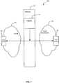
- Fig. 1 depicts a system 100 for providing dynamic adjustment of call characteristics according to one embodiment of the present invention.
- system 100 includes a gateway 102, PSTN device 104, VOIP device 106, a VOIP network 108, and a PSTN 110.
- the steps include: allowing a communication between a first device and a second device at the gateway, the communication being routed through a first network and second network, the first network being different from the second network; receiving an indication at an adjuster of the gateway that a characteristic should be adjusted for the communication; and adjusting the characteristic at the gateway during the communication based on the indication, the adjustment being effected at the first device and the second device during the communication.
- Fig. 1 depicts a system 100 for providing dynamic adjustment of call characteristics according to one embodiment of the present invention.
- system 100 includes a gateway 102, PSTN device 104, VOIP device 106, a VOIP network 108, and a PSTN 110.
- Gateway 102 is configured to connect devices in a communication.
- the communication may be any exchange of data between devices.
- the communication may be any network to network transition, any media exchange, a telephone call, a download of data, web conference, or any communication session, etc.
- a communication will be referred to as a call between devices.
- Network 110 may be a public switched network (referred to as "PSTN 110 hereinafter) that includes a collection of interconnected voice-oriented public telephone networks.
- PSTN 110 may also be referred to as a plain old telephone service (POTS) network.
- POTS plain old telephone service
- Circuit-switching telephone networks may be connected to provide PSTN 110.
- Network 108 may be a VOIP network (referred to as VOIP network 108 hereinafter) that includes any packet based switching network(s).
- VOIP network 108 delivers voice communications using internet protocol (IP) technology.
- IP internet protocol
- voice information is in a digital form and sent using packets. This is in contrast to data that is sent using a traditional circuit switched-protocol used in PSTN 110.
- VOIP network 108 may use various protocols, such as H.323, session initiation protocol (SIP), etc.
- call characteristics may be dynamically adjusted for a call routed through any networks.
- call characteristics may be adjusted for any network transition between disparate networks.
- network transitions may be SIP to VOIP, H323 or VOIP, or SIP to PoC (push to Talk), internet to IMS (IP Multimedia subsystem), or any exchange of other media than voice (e.g. video, music, web conference, etc.).
- network 108 and network 110 may be the same network (e.g., same protocol) but there may be a transition from one network to another network.
- PSTN device 104 includes any device that communicates using PSTN 110.
- PSTN device 104 may be an end user's telephone used to make a telephone call.
- PSTN device 104 may be any other device used to route the call, such as any switches, or any other devices in a PSTN network.
- VOIP device 106 includes any device capable communicating with VOIP network 108.
- VOIP device 106 may be an end user device used to initiate a call, such as a computer, cellular phone, instant messenger client, VOIP telephone, softphone, voice chat client, etc.
- VOIP device 106 may be a server, an agent for an end user device, such as a VOIP agent that communicates with gateway 102 while routing the call, etc.
- VOIP device 106 may be a SIP agent for an end user device (e.g., telephone).
- gateway 102 may be used to connect calls between any devices.
- PSTN device 104 and VOIP device 106 may be any devices that are compatible with the networks routing the call.
- Adjustor 112 is configured to dynamically adjust a call characteristic during a call between PSTN device 104 and VOIP device 106.
- a call may be any communication between PSTN device 104 and VOIP device 106.
- the call may be a voice call, a data call, a streaming media communication, any download of information, etc.
- an indication is received at adjustor 112.
- the indication may be received from PSTN device 104, VOIP device 106, a module in gateway 102, a remote agent different from PSTN device 104 and VOIP device 106, or any other device. Different scenarios of receiving the indication will be described below.
- Adjustor 112 uses the indication to adjust a characteristic during the call.
- the characteristic may be any characteristic of a call, such as gain, impedance, volume, echo, etc. This adjustment is made for the call and affects the PSTN device 104 and VOIP device 106 during the call. Thus, adjustments may be dynamically made on a call by call basis.
- characteristics, such as gain, for gateway 102 are calibrated for all calls being connected through gateway 102 or for an endpoint (e.g., a telephone, or any end device). This is a global adjustment that is supposed to maximize call quality. However, due to certain factors, the globally adjusted gain may not be satisfactory for all calls. For example, factors that contribute to characteristics that affect calls may vary for each call. The type of connection (e.g., speed of the connection), impedance mismatches, the type of PSTN device or VOIP device, the distance, etc. may affect the call characteristics of a call. For example, when transitions between networks occur, the calls may be affected. Thus, call characteristics may be poor for specific calls.
- embodiments of the present invention provide dynamic adjustments while a call is being made. This is more advantageous than globally adjusting characteristics for all calls (i.e., calibrating the gateway). Also, it is typically not possible for devices 104 and 106 to make the adjustments themselves without gateway 102.
- a call may result in poor volume or echo on one or both sides of gateway 102.
- Latencies that are introduced into the call by PSTN 110 or VOIP network 108 may affect call characteristics.
- the latency may be delays that are introduced by a network.
- the latencies may be because of packet latencies or bandwidth dips in the VOIP network side. These latencies may result in poor volume.
- impedance mismatches between PSTN 110 and VOIP network 108 may result in poor call characteristics.
- impedance mismatches may result in echo (i.e., the echoing of words).
- gain may be adjusted at gateway 102 to adjust the call characteristics while the call is taking place.
- Gain may be the amplification factor, which is the extent to which an analog amplifier boosts the strength of a signal. By increasing the gain of a signal of the call, the volume may be adjusted. Also, by adjusting the gateway impedance, impedance mismatches on different sides of gateway 102 (e.g., the VOIP side and PSTN side) can be eliminated thereby removing echo in a call.
- embodiments of the present invention allow adjustor 112 to adjust the call characteristics on a call by call basis.
- the call characteristics may be adjusted for that call dynamically.
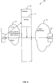
- Fig. 2 shows a first embodiment of system 100 according to embodiments of the present invention.
- a call is connected between PSTN device 104 and VOIP device 106. While on the call, PSTN device 104 and/or VOIP device 106 may determine that call characteristics are poor. For example, the volume may be too low or too high, or an echo may be occurring.
- VOIP device 106 is provided with a controller that can send an indication to adjustor 112 to change certain call characteristics.
- the indication may be sent to increase or decrease the volume on the call.
- the indication may indicate that an echo is occurring.
- the indication may be sent by VOIP device 106 using a web service call, a proprietary call, or any other methods of communicating with adjustor 112.
- proprietary or web service calls may configured such that VOIP device 106 knows where to send the indication and network 108 knows how to send it to adjustor 112.
- the message sent may be a session initiation protocol message, such as a SIMPLE message, a MSRP message or via SIP NOTIFY events.
- the SIP message may be sent to an address for gateway 102. Other methods of communicating the indication to gateway 102 may also be appreciated.
- VOIP device 106 may include a user interface that is used to send an indication to adjustor 112.
- the user interface may include a feature that allows the user to change a call characteristic, such as increasing/decreasing volume, decreasing echo, etc.
- an indication can be sent. For example, if a user of PSTN device 104 would like call characteristics to be changed, the user may tell the user of VOIP device 106 that the call characteristics need to be changed. The user of PSTN device 104 may request that volume increased or decreased or say that an echo is being heard. Also, the exchange between users may take place via exchanges of data in other channels. For example, a user may send an instant message to the other user saying the volume is too low. The notification may also be automated as discussed after via systems that detect the problems on the other side and communicate it to gateway 102 or the other device or user. A user of VOIP device 106 may use the interface to cause VOIP device 106 to send an indication for a change in call characteristics.
- Adjustor 112 is configured to adjust the call characteristics when the indication is received.
- the indication may indicate how much a call characteristic should be changed. For example, the indication may indicate that the volume should be increased or decreased a certain amount, etc. Also, the indication may indicate that a certain amount of echo is being heard.
- Adjustor 112 is then configured to adjust the call characteristics during the call. Then, once the call characteristics are changed, the changes are effected on the call for PSTN device 104 and VOIP device 106. In one embodiment, gain may be adjusted for the call. By adjusting the gain, the volume may be increased or decreased. The above process may be performed iteratively until the call characteristics are satisfactory.
- VOIP device 106 may send indications to adjustor 112 to adjust the gain and/or impedance of gateway 102 to eliminate echo. Feedback may continue to determine if the echo being detected is getting worse or better.
- the impedance between PSTN device 104 and VOIP device 106 may be changed to remove the differences between impedances of both devices. By changing the impedances to remove the differences, the echo may be removed. Changing impedance is one way of changing the gain for a particular call. It will be recognized that other methods of removing or canceling echo may be provided (e.g. introducing artificial delays, etc.).
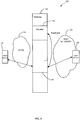
- Fig. 3 shows a second embodiment of system 100 according to embodiments of the present invention.
- a module 302 in gateway 102 is configured to detect call characteristics of a call between PSTN device 104 and VOIP device 106.
- module 302 may be able to check the volume on the call.
- module 302 automatically measures a gain that is being generated on the call. For example, the gain generated by a digital or analog PSTN signal may be measured.
- module 302 may listen to the call to determine if volume needs to be adjusted. Also, module 302 may listen for an echo.
- module 302 sends an indication to adjustor 112. For example, module 302 may send an indication that indicates that the gain is too low or too high (any channel may be used to send the indication). Adjustor 112 then adjusts the gain for the call thereby adjusting the volume or canceling the echo.
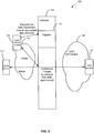
- Fig. 4 depicts a third embodiment of system 100 according to embodiments of the present invention.
- PSTN device 104 may be used to adjust call characteristics.
- PSTN device 104 may use a separate channel to communicate the indication to change a call characteristic to adjustor 112.
- PSTN device 104 may be aware of gateway 102 and use session information to request a change in call characteristics.
- PSTN device 104 may also include a data channel, such as an Internet connection.
- a PSTN telephone can be on the call and then open up a data channel to adjustor 112. This may be achieved by posting via a web service or by a web page.
- the call may be identified using the VOIP phone number for VOIP device 106, IP address for VOIP device 106, or any other identifying information.
- all incoming calls for the telephone number used by the PSTN device 104 may be listed on the web page. The user may select the call corresponding to the incoming call and choose to send an indication to gateway 102. The indication is then sent to adjuster 112.
- the web page may include an ability to adjust the volume or cancel the echo for all calls that are currently active for PSTN device 104.
- the indication is then sent to adjustor 112.
- Adjustor 112 can then change the call characteristics for the call.
- Fig. 5 depicts a fourth embodiment of system 100 according to embodiments of the present invention.
- An agent 502 is able to check call characteristics on a call between PSTN device 104 and VOIP device 106. Agent 502 then sends an indication to adjustor 112 that is used to change the call characteristics.
- Agent 502 may be a probe that is added to PSTN 110.
- the probe may be an additional telephone that is conferenced into the call (e.g., by using a conference bridge). For example, when a call is made using PSTN device 104, agent 502 is conferenced into the call.
- the probe checks the call characteristics to determine if they are sufficient. For example, the volume or echo may be checked by checking the gain on the call.
- Agent 502 then sends an indication to adjustor 112.
- the indication may be sent to gateway 102.
- agent 502 is configured to communicate with adjustor 112 through a data channel.
- Adjustor 112 may then adjust the call characteristics, such as by adjusting the gain.
- agent 502 may drop out of the call. Also, if agent 502 determines that the call characteristics do not need any changes, agent 502 may just drop of out of the call without performing any actions.
- inventions provide dynamic adjustment of call characteristics on a per call basis.
- the call characteristics that can be changed are characteristics that cannot be changed using solely VOIP device 106 and/or PSTN device 102.
- the gain is changed by gateway 102 in order to adjust volume or cancel echo for a call.
- the gain on a call cannot be changed by VOIP device 106 and/or PSTN 102 without using gateway 102.
- gateway 102 is used to dynamically adjust the call characteristics during a call. This provides specific tuning for a call rather than a global adjustment across all calls.
- Fig. 6 is a simplified block diagram of data processing system 600 that may be used to perform processing according to an embodiment of the present invention.
- data processing system 600 includes at least one processor 602, which communicates with a number of peripheral devices via a bus subsystem 604.
- peripheral devices may include a storage subsystem 606, comprising a memory subsystem 608 and a file storage subsystem 610, user interface input devices 612, user interface output devices 614, and a network interface subsystem 616.
- the input and output devices allow user interaction with data processing system 602.
- Network interface subsystem 616 provides an interface to other computer systems, networks, and storage resources.
- the networks may include the Internet, a local area network (LAN), a wide area network (WAN), a wireless network, an intranet, a private network, a public network, a switched network, or any other suitable communication network.
- Network interface subsystem 616 serves as an interface for receiving data from other sources and for transmitting data to other sources from data processing system 600.
- Embodiments of network interface subsystem 616 include an Ethernet card, a modem (telephone, satellite, cable, ISDN, etc.), (asynchronous) digital subscriber line (DSL) units, and the like.
- User interface input devices 612 may include a keyboard, pointing devices such as a mouse, trackball, touchpad, or graphics tablet, a scanner, a barcode scanner, a touchscreen incorporated into the display, audio input devices such as voice recognition systems, microphones, and other types of input devices.
- pointing devices such as a mouse, trackball, touchpad, or graphics tablet
- audio input devices such as voice recognition systems, microphones, and other types of input devices.
- use of the term "input device” is intended to include all possible types of devices and ways to input information to data processing system 600.
- User interface output devices 614 may include a display subsystem, a printer, a fax machine, or non-visual displays such as audio output devices.
- the display subsystem may be a cathode ray tube (CRT), a flat-panel device such as a liquid crystal display (LCD), or a projection device.
- CTR cathode ray tube
- LCD liquid crystal display
- output device is intended to include all possible types of devices and ways to output information from data processing system 600.
- Storage subsystem 606 may be configured to store the basic programming and data constructs that provide the functionality of the present invention. For example, according to an embodiment of the present invention, software modules implementing the functionality of the present invention may be stored in storage subsystem 606. These software modules may be executed by processor(s) 602. Storage subsystem 606 may also provide a repository for storing data used in accordance with the present invention. Storage subsystem 606 may comprise memory subsystem 608 and file/disk storage subsystem 610.
- Memory subsystem 608 may include a number of memories including a main random access memory (RAM) 618 for storage of instructions and data during program execution and a read only memory (ROM) 620 in which fixed instructions are stored.
- File storage subsystem 610 provides persistent (non-volatile) storage for program and data files, and may include a hard disk drive, a floppy disk drive along with associated removable media, a Compact Disk Read Only Memory (CD-ROM) drive, an optical drive, removable media cartridges, and other like storage media.
- CD-ROM Compact Disk Read Only Memory
- Bus subsystem 604 provides a mechanism for letting the various components and subsystems of data processing system 602 communicate with each other as intended. Although bus subsystem 604 is shown schematically as a single bus, alternative embodiments of the bus subsystem may utilize multiple busses.
- Data processing system 600 can be of varying types including a personal computer, a portable computer, a workstation, a network computer, a mainframe, a kiosk, or any other data processing system. Due to the ever-changing nature of computers and networks, the description of data processing system 600 depicted in Fig. 6 is intended only as a specific example for purposes of illustrating the preferred embodiment of the computer system. Many other configurations having more or fewer components than the system depicted in Fig. 6 are possible.
- the present invention can be implemented in the form of control logic in software or hardware or a combination of both.
- the control logic may be stored in an information storage medium as a plurality of instructions adapted to direct an information processing device to perform a set of steps disclosed in embodiments of the present invention. Based on the disclosure and teachings provided herein, a person of ordinary skill in the art will appreciate other ways and/or methods to implement the present invention.
Description
- The present invention generally relates to telecommunications and more specifically to dynamic adjustment of call characteristics at a gateway on per call basis.
- Voice over internet protocol (VOIP) solutions are being used by many users who make telephone calls. VOIP provides an inexpensive and flexible telephony system that may be used in lieu of or in conjunction with a public switch telephone network (PSTN).
- Although VOIP is used, calls may still be connected between PSTN telephones and VOIP telephones. Thus, the calls go through a PSTN network and VOIP network. When these calls occur, call quality may be poor because of the differences in the networks. For example, the PSTN side and/or VOIP side may suffer from poor volume level and/or echo.
- Gateways may be calibrated in an attempt to minimize poor call quality. For example, the gain may be calibrated for calls made through the gateway. This calibration is a global adjustment for all calls made through the gateway or calls from an end point.
- Some telephones may have a volume adjustment local to the handset that may used to adjust the volume on the phone. This solution, however, does not remedy the poor call quality for the call (e.g., as perceived by other participants).
-
US 2002/0101830-A1 discloses adjustment of call characteristics based on indications received by an echo canceller of a gateway.GB-2-399-960-A WO 2004/006462-A1 describe similar systems.US 2005/0152524-A1 describes a method for automatically adjusting the volume of individual conference call participants. - According to a first aspect of the invention, there is provided a method as set out in claim 1.
- According to a second aspect of the invention, there is provided a system as set out in claim 11.
- According to a third aspect of the invention, there is provided an information storage medium as set out in claim 15.
- In one embodiment, techniques for dynamically adjusting volume or eliminating echo during a call are provided. A gateway is provided that allows a call between a first device and a second device. The call may be routed through a first network and a second network. The first network may be PSTN network and the second network may be a VOIP network. An indication may be received at the gateway that indicates a call characteristic should be adjusted for the call. For example, the indication may indicate the volume or echo should be adjusted. The gateway may then adjust the volume during the call or eliminating
- A further understanding of the nature and the advantages of the inventions disclosed herein may be realized by reference of the remaining portions of the specification and the attached drawings.
-
-
Fig. 1 depicts a system for providing dynamic adjustment of call characteristics according to one embodiment of the present invention. -
Fig. 2 depicts a first embodiment of the system according to embodiments of the present invention. -
Fig. 3 depicts a second embodiment of the system according to embodiments of the present invention. -
Fig. 4 depicts a third embodiment of the system according to embodiments of the present invention. -
Fig. 5 depicts a fourth embodiment of the system according to embodiments of the present invention. -
Fig. 6 is a simplified block diagram of a data processing system that may be used to perform processing according to an embodiment of the present invention. -
Fig. 1 depicts asystem 100 for providing dynamic adjustment of call characteristics according to one embodiment of the present invention. As shown,system 100 includes agateway 102,PSTN device 104,VOIP device 106, aVOIP network 108, and aPSTN 110. is provided. The steps include: allowing a communication between a first device and a second device at the gateway, the communication being routed through a first network and second network, the first network being different from the second network; receiving an indication at an adjuster of the gateway that a characteristic should be adjusted for the communication; and adjusting the characteristic at the gateway during the communication based on the indication, the adjustment being effected at the first device and the second device during the communication. - A further understanding of the nature and the advantages of the inventions disclosed herein may be realized by reference of the remaining portions of the specification and the attached drawings.
-
-
Fig. 1 depicts a system for providing dynamic adjustment of call characteristics according to one embodiment of the present invention. -
Fig. 2 depicts a first embodiment of the system according to embodiments of the present invention. -
Fig. 3 depicts a second embodiment of the system according to embodiments of the present invention. -
Fig. 4 depicts a third embodiment of the system according to embodiments of the present invention. -
Fig. 5 depicts a fourth embodiment of the system according to embodiments of the present invention. -
Fig. 6 is a simplified block diagram of a data processing system that may be used to perform processing according to an embodiment of the present invention. -
Fig. 1 depicts asystem 100 for providing dynamic adjustment of call characteristics according to one embodiment of the present invention. As shown,system 100 includes agateway 102,PSTN device 104,VOIP device 106, aVOIP network 108, and aPSTN 110. - Gateway 102 is configured to connect devices in a communication. The communication may be any exchange of data between devices. For example, the communication may be any network to network transition, any media exchange, a telephone call, a download of data, web conference, or any communication session, etc. For discussion purposes, a communication will be referred to as a call between devices.
- Network 110 may be a public switched network (referred to as "PSTN 110 hereinafter) that includes a collection of interconnected voice-oriented public telephone networks. PSTN 110 may also be referred to as a plain old telephone service (POTS) network. Circuit-switching telephone networks may be connected to provide PSTN 110.
-
Network 108 may be a VOIP network (referred to asVOIP network 108 hereinafter) that includes any packet based switching network(s). VOIPnetwork 108 delivers voice communications using internet protocol (IP) technology. Generally, voice information is in a digital form and sent using packets. This is in contrast to data that is sent using a traditional circuit switched-protocol used in PSTN 110. VOIPnetwork 108 may use various protocols, such as H.323, session initiation protocol (SIP), etc. - Although calls are described as being routed through
VOIP network 108 and PSTN 110, call characteristics may be dynamically adjusted for a call routed through any networks. In one embodiment, call characteristics may be adjusted for any network transition between disparate networks. For example, network transitions may be SIP to VOIP, H323 or VOIP, or SIP to PoC (push to Talk), internet to IMS (IP Multimedia subsystem), or any exchange of other media than voice (e.g. video, music, web conference, etc.). Also,network 108 andnetwork 110 may be the same network (e.g., same protocol) but there may be a transition from one network to another network. -
PSTN device 104 includes any device that communicates usingPSTN 110. For example,PSTN device 104 may be an end user's telephone used to make a telephone call. Also,PSTN device 104 may be any other device used to route the call, such as any switches, or any other devices in a PSTN network. -
VOIP device 106 includes any device capable communicating withVOIP network 108. For example,VOIP device 106 may be an end user device used to initiate a call, such as a computer, cellular phone, instant messenger client, VOIP telephone, softphone, voice chat client, etc. Also,VOIP device 106 may be a server, an agent for an end user device, such as a VOIP agent that communicates withgateway 102 while routing the call, etc. In one embodiment,VOIP device 106 may be a SIP agent for an end user device (e.g., telephone). - Although the call is shown as being connected between a
PSTN device 104 and aVOIP device 106, it will be understood thatgateway 102 may be used to connect calls between any devices. For example,PSTN device 104 andVOIP device 106 may be any devices that are compatible with the networks routing the call. -
Adjustor 112 is configured to dynamically adjust a call characteristic during a call betweenPSTN device 104 andVOIP device 106. A call may be any communication betweenPSTN device 104 andVOIP device 106. For example, the call may be a voice call, a data call, a streaming media communication, any download of information, etc. - In one embodiment, an indication is received at
adjustor 112. The indication may be received fromPSTN device 104,VOIP device 106, a module ingateway 102, a remote agent different fromPSTN device 104 andVOIP device 106, or any other device. Different scenarios of receiving the indication will be described below. -
Adjustor 112 uses the indication to adjust a characteristic during the call. The characteristic may be any characteristic of a call, such as gain, impedance, volume, echo, etc. This adjustment is made for the call and affects thePSTN device 104 andVOIP device 106 during the call. Thus, adjustments may be dynamically made on a call by call basis. - In one embodiment, characteristics, such as gain, for
gateway 102 are calibrated for all calls being connected throughgateway 102 or for an endpoint (e.g., a telephone, or any end device). This is a global adjustment that is supposed to maximize call quality. However, due to certain factors, the globally adjusted gain may not be satisfactory for all calls. For example, factors that contribute to characteristics that affect calls may vary for each call. The type of connection (e.g., speed of the connection), impedance mismatches, the type of PSTN device or VOIP device, the distance, etc. may affect the call characteristics of a call. For example, when transitions between networks occur, the calls may be affected. Thus, call characteristics may be poor for specific calls. Accordingly, embodiments of the present invention provide dynamic adjustments while a call is being made. This is more advantageous than globally adjusting characteristics for all calls (i.e., calibrating the gateway). Also, it is typically not possible fordevices gateway 102. - Also, if a global change is made, a call that is experiencing poor call characteristics may not be affected by the global change. Thus, users on existing calls would have to disconnect their call and initiate a new call. Further, the global changes may not be acceptable for all calls being made.
- As described above, factors that are introduced on a call by call basis may be result in poor call characteristics. For example, a call may result in poor volume or echo on one or both sides of
gateway 102. Latencies that are introduced into the call byPSTN 110 orVOIP network 108 may affect call characteristics. The latency may be delays that are introduced by a network. For example, the latencies may be because of packet latencies or bandwidth dips in the VOIP network side. These latencies may result in poor volume. - Also, impedance mismatches between
PSTN 110 andVOIP network 108 may result in poor call characteristics. For example, impedance mismatches may result in echo (i.e., the echoing of words). - In one embodiment, gain may be adjusted at
gateway 102 to adjust the call characteristics while the call is taking place. Gain may be the amplification factor, which is the extent to which an analog amplifier boosts the strength of a signal. By increasing the gain of a signal of the call, the volume may be adjusted. Also, by adjusting the gateway impedance, impedance mismatches on different sides of gateway 102 (e.g., the VOIP side and PSTN side) can be eliminated thereby removing echo in a call. - In order to address the above problems, embodiments of the present invention allow
adjustor 112 to adjust the call characteristics on a call by call basis. Thus, during a call, the call characteristics may be adjusted for that call dynamically. - The following figures depict various embodiments of systems for dynamically adjusting call characteristics. Although these embodiments are discussed, it will be recognized that other systems and methods may be used.
-
Fig. 2 shows a first embodiment ofsystem 100 according to embodiments of the present invention. A call is connected betweenPSTN device 104 andVOIP device 106. While on the call,PSTN device 104 and/orVOIP device 106 may determine that call characteristics are poor. For example, the volume may be too low or too high, or an echo may be occurring. -
VOIP device 106 is provided with a controller that can send an indication toadjustor 112 to change certain call characteristics. For example, the indication may be sent to increase or decrease the volume on the call. Also, the indication may indicate that an echo is occurring. - The indication may be sent by
VOIP device 106 using a web service call, a proprietary call, or any other methods of communicating withadjustor 112. For example, proprietary or web service calls may configured such thatVOIP device 106 knows where to send the indication andnetwork 108 knows how to send it toadjustor 112. Also, the message sent may be a session initiation protocol message, such as a SIMPLE message, a MSRP message or via SIP NOTIFY events. The SIP message may be sent to an address forgateway 102. Other methods of communicating the indication togateway 102 may also be appreciated. - In one embodiment,
VOIP device 106 may include a user interface that is used to send an indication toadjustor 112. The user interface may include a feature that allows the user to change a call characteristic, such as increasing/decreasing volume, decreasing echo, etc. - In one embodiment, if a user decides that call characteristics are poor, then an indication can be sent. For example, if a user of
PSTN device 104 would like call characteristics to be changed, the user may tell the user ofVOIP device 106 that the call characteristics need to be changed. The user ofPSTN device 104 may request that volume increased or decreased or say that an echo is being heard. Also, the exchange between users may take place via exchanges of data in other channels. For example, a user may send an instant message to the other user saying the volume is too low. The notification may also be automated as discussed after via systems that detect the problems on the other side and communicate it togateway 102 or the other device or user. A user ofVOIP device 106 may use the interface to causeVOIP device 106 to send an indication for a change in call characteristics. -
Adjustor 112 is configured to adjust the call characteristics when the indication is received. The indication may indicate how much a call characteristic should be changed. For example, the indication may indicate that the volume should be increased or decreased a certain amount, etc. Also, the indication may indicate that a certain amount of echo is being heard. -
Adjustor 112 is then configured to adjust the call characteristics during the call. Then, once the call characteristics are changed, the changes are effected on the call forPSTN device 104 andVOIP device 106. In one embodiment, gain may be adjusted for the call. By adjusting the gain, the volume may be increased or decreased. The above process may be performed iteratively until the call characteristics are satisfactory. - If echo is being eliminated, then feedback may be provided by
PSTN device 102 as echo is adjusted.VOIP device 106 may send indications toadjustor 112 to adjust the gain and/or impedance ofgateway 102 to eliminate echo. Feedback may continue to determine if the echo being detected is getting worse or better. In one embodiment, the impedance betweenPSTN device 104 andVOIP device 106 may be changed to remove the differences between impedances of both devices. By changing the impedances to remove the differences, the echo may be removed. Changing impedance is one way of changing the gain for a particular call. It will be recognized that other methods of removing or canceling echo may be provided (e.g. introducing artificial delays, etc.). -
Fig. 3 shows a second embodiment ofsystem 100 according to embodiments of the present invention. As shown, amodule 302 ingateway 102 is configured to detect call characteristics of a call betweenPSTN device 104 andVOIP device 106. For example,module 302 may be able to check the volume on the call. In one embodiment,module 302 automatically measures a gain that is being generated on the call. For example, the gain generated by a digital or analog PSTN signal may be measured. In another embodiment,module 302 may listen to the call to determine if volume needs to be adjusted. Also,module 302 may listen for an echo. - If call characteristics need to be changed,
module 302 sends an indication toadjustor 112. For example,module 302 may send an indication that indicates that the gain is too low or too high (any channel may be used to send the indication).Adjustor 112 then adjusts the gain for the call thereby adjusting the volume or canceling the echo. -
Fig. 4 depicts a third embodiment ofsystem 100 according to embodiments of the present invention. As shown,PSTN device 104 may be used to adjust call characteristics. For example,PSTN device 104 may use a separate channel to communicate the indication to change a call characteristic toadjustor 112. -
PSTN device 104 may be aware ofgateway 102 and use session information to request a change in call characteristics. For example,PSTN device 104 may also include a data channel, such as an Internet connection. A PSTN telephone can be on the call and then open up a data channel toadjustor 112. This may be achieved by posting via a web service or by a web page. For example, the call may be identified using the VOIP phone number forVOIP device 106, IP address forVOIP device 106, or any other identifying information. In one example, all incoming calls for the telephone number used by thePSTN device 104 may be listed on the web page. The user may select the call corresponding to the incoming call and choose to send an indication togateway 102. The indication is then sent toadjuster 112. - The web page may include an ability to adjust the volume or cancel the echo for all calls that are currently active for
PSTN device 104. The indication is then sent toadjustor 112.Adjustor 112 can then change the call characteristics for the call. -
Fig. 5 depicts a fourth embodiment ofsystem 100 according to embodiments of the present invention. Anagent 502 is able to check call characteristics on a call betweenPSTN device 104 andVOIP device 106.Agent 502 then sends an indication toadjustor 112 that is used to change the call characteristics. -
Agent 502 may be a probe that is added toPSTN 110. The probe may be an additional telephone that is conferenced into the call (e.g., by using a conference bridge). For example, when a call is made usingPSTN device 104,agent 502 is conferenced into the call. The probe checks the call characteristics to determine if they are sufficient. For example, the volume or echo may be checked by checking the gain on the call. -
Agent 502 then sends an indication toadjustor 112. The indication may be sent togateway 102. For example,agent 502 is configured to communicate withadjustor 112 through a data channel.Adjustor 112 may then adjust the call characteristics, such as by adjusting the gain. - Once
agent 502 has checked the call characteristics and sent an indication toadjustor 112,agent 502 may drop out of the call. Also, ifagent 502 determines that the call characteristics do not need any changes,agent 502 may just drop of out of the call without performing any actions. - Accordingly, embodiments provide dynamic adjustment of call characteristics on a per call basis. The call characteristics that can be changed are characteristics that cannot be changed using solely
VOIP device 106 and/orPSTN device 102. For example, the gain is changed bygateway 102 in order to adjust volume or cancel echo for a call. The gain on a call cannot be changed byVOIP device 106 and/orPSTN 102 without usinggateway 102. Thus,gateway 102 is used to dynamically adjust the call characteristics during a call. This provides specific tuning for a call rather than a global adjustment across all calls. - Accordingly, quality and customer satisfaction is provided. Users can adjust the call themselves when poor call quality is noticed. Because of the differences in various networks connecting calls, it may be likely that poor call quality may occur. Thus, if poor volume or significant echo occurs on one side of
gateway 102, it can be adjusted using the techniques provided above during the call. Thus, users do not have to hang up and attempt a call again. The adjustment may also be provided automatically or based on user feedback. -
Fig. 6 is a simplified block diagram ofdata processing system 600 that may be used to perform processing according to an embodiment of the present invention. As shown inFig. 6 ,data processing system 600 includes at least oneprocessor 602, which communicates with a number of peripheral devices via abus subsystem 604. These peripheral devices may include astorage subsystem 606, comprising amemory subsystem 608 and afile storage subsystem 610, userinterface input devices 612, userinterface output devices 614, and anetwork interface subsystem 616. The input and output devices allow user interaction withdata processing system 602. -
Network interface subsystem 616 provides an interface to other computer systems, networks, and storage resources. The networks may include the Internet, a local area network (LAN), a wide area network (WAN), a wireless network, an intranet, a private network, a public network, a switched network, or any other suitable communication network.Network interface subsystem 616 serves as an interface for receiving data from other sources and for transmitting data to other sources fromdata processing system 600. Embodiments ofnetwork interface subsystem 616 include an Ethernet card, a modem (telephone, satellite, cable, ISDN, etc.), (asynchronous) digital subscriber line (DSL) units, and the like. - User
interface input devices 612 may include a keyboard, pointing devices such as a mouse, trackball, touchpad, or graphics tablet, a scanner, a barcode scanner, a touchscreen incorporated into the display, audio input devices such as voice recognition systems, microphones, and other types of input devices. In general, use of the term "input device" is intended to include all possible types of devices and ways to input information todata processing system 600. - User
interface output devices 614 may include a display subsystem, a printer, a fax machine, or non-visual displays such as audio output devices. The display subsystem may be a cathode ray tube (CRT), a flat-panel device such as a liquid crystal display (LCD), or a projection device. In general, use of the term "output device" is intended to include all possible types of devices and ways to output information fromdata processing system 600. -
Storage subsystem 606 may be configured to store the basic programming and data constructs that provide the functionality of the present invention. For example, according to an embodiment of the present invention, software modules implementing the functionality of the present invention may be stored instorage subsystem 606. These software modules may be executed by processor(s) 602.Storage subsystem 606 may also provide a repository for storing data used in accordance with the present invention.Storage subsystem 606 may comprisememory subsystem 608 and file/disk storage subsystem 610. -
Memory subsystem 608 may include a number of memories including a main random access memory (RAM) 618 for storage of instructions and data during program execution and a read only memory (ROM) 620 in which fixed instructions are stored.File storage subsystem 610 provides persistent (non-volatile) storage for program and data files, and may include a hard disk drive, a floppy disk drive along with associated removable media, a Compact Disk Read Only Memory (CD-ROM) drive, an optical drive, removable media cartridges, and other like storage media. -
Bus subsystem 604 provides a mechanism for letting the various components and subsystems ofdata processing system 602 communicate with each other as intended. Althoughbus subsystem 604 is shown schematically as a single bus, alternative embodiments of the bus subsystem may utilize multiple busses. -
Data processing system 600 can be of varying types including a personal computer, a portable computer, a workstation, a network computer, a mainframe, a kiosk, or any other data processing system. Due to the ever-changing nature of computers and networks, the description ofdata processing system 600 depicted inFig. 6 is intended only as a specific example for purposes of illustrating the preferred embodiment of the computer system. Many other configurations having more or fewer components than the system depicted inFig. 6 are possible. - The present invention can be implemented in the form of control logic in software or hardware or a combination of both. The control logic may be stored in an information storage medium as a plurality of instructions adapted to direct an information processing device to perform a set of steps disclosed in embodiments of the present invention. Based on the disclosure and teachings provided herein, a person of ordinary skill in the art will appreciate other ways and/or methods to implement the present invention.
- The above description is illustrative but not restrictive. Many variations of the invention will become apparent to those skilled in the art upon review of the disclosure. The scope of the invention should, therefore, be determined not with reference to the above description, but instead should be determined with reference to the pending claims.
Claims (15)
- A method for dynamically adjusting a characteristic for a communication using a gateway (102), the method comprising:allowing, at the gateway (102, a communication between a first end device (104) and a second end device (105), the communication being routed through a first network (110) and a second network (108), the first network (110) being a PSTN and being different from the second network (108);receiving an indication at an adjuster (112) comprised by the gateway, the indication identifying a characteristic to be adjusted for the communication, the indication originating from a third device (502) in response to the checking of at least one characteristic of the communication by the third (502) device, the third device (502) being conferenced into the communication via the first network;adjusting, by said adjuster (112), in response to receiving the indication, the characteristic at the gateway (102) during the communication in dependence on the indication, such that the effect of the adjustment is experienced at the first end device (104) and/or the second end device (105) during the communication;wherein, the third device (502) is configured to communicate with the gateway via a data channel.
- The method of claim 1, wherein the characteristic comprises a volume characteristic or echo characteristic.
- The method of claim 1, wherein the characteristic is adjusted by adjusting gain or impedance for the communication.
- The method of claim 1, wherein the first network (110) comprises a PSTN network and the second network (108) comprises a VOIP network.
- The method of claim 1, wherein the adjustment is made on a per communication basis.
- The method of claim 1, wherein adjusting the gain or impedance comprises adjusting a volume level for the communication.
- The method of claim 6, wherein adjusting the gain or impedance comprises eliminating an echo for the communication.
- The method of any preceding claim, wherein, the third device is coupled to the communication and, once the third device (502) has sent the indicator to the adjuster (112), the third device (502) is configured to drop out of the communication.
- The method of claim 1, wherein the third device (502) is coupled to the communication and configured to check the volume of the communication.
- The method according to claim 4, or claim 8 when dependent on claim 4, wherein the third device is an agent configured to communicate via the PSTN network.
- A system (100) for dynamically adjusting a characteristic for a communication, the system comprising:a first end device (104) configured to communicate using a first network (110);a second end device (105) configured to communicate using a second network (108);a gateway (102) configured to allow a communication between the first end device (104) and the second end device (105), the communication being routed through the first network (110) and the second network (108), the first network (110) being a PSTN and being different from the second network (108); anda third device (502) configured to communicate with the gateway via a data channel;the gateway (102) comprising:
an adjuster (112) configured to:receive an indication identifying a characteristic of the communication to be adjusted for the call, the indication originating from the third device (502) in response to checking, by conferencing into the call via the first network, of at least one characteristic for the communication by the third device; andadjust the characteristic during the communication in dependence on the indication, the adjustment being effected at the first end device (104) and/or the second device (105) during the communication. - The system of claim 11, wherein the characteristic comprises a volume characteristic or echo characteristic.
- The system of claim 11, wherein the characteristic is adjusted by adjusting gain or impedance for the call.
- The system of claim 11, wherein the first network (110) comprises a PSTN network and the second network (108) comprises a VOIP network.
- An information storage medium (606) comprising instructions which, when executed by a computer implementing the gateway comprised in the system of claim 11, cause the computer to perform the method of any claims 1 to 10.
Applications Claiming Priority (2)
| Application Number | Priority Date | Filing Date | Title |
|---|---|---|---|
| US11/264,787 US8077700B2 (en) | 2005-10-31 | 2005-10-31 | Dynamic call characteristic control on a per call basis |
| PCT/US2006/008219 WO2007053174A1 (en) | 2005-10-31 | 2006-03-07 | Dynamic call characteristic control on a per call basis |
Publications (2)
| Publication Number | Publication Date |
|---|---|
| EP1943826A1 EP1943826A1 (en) | 2008-07-16 |
| EP1943826B1 true EP1943826B1 (en) | 2019-05-01 |
Family
ID=36572268
Family Applications (1)
| Application Number | Title | Priority Date | Filing Date |
|---|---|---|---|
| EP06737395.1A Active EP1943826B1 (en) | 2005-10-31 | 2006-03-07 | Dynamic call characteristic control on a per call basis |
Country Status (7)
| Country | Link |
|---|---|
| US (1) | US8077700B2 (en) |
| EP (1) | EP1943826B1 (en) |
| JP (1) | JP5214456B2 (en) |
| CN (1) | CN101305591B (en) |
| AU (1) | AU2006309272B2 (en) |
| CA (1) | CA2626455C (en) |
| WO (1) | WO2007053174A1 (en) |
Families Citing this family (9)
| Publication number | Priority date | Publication date | Assignee | Title |
|---|---|---|---|---|
| CN101651659A (en) * | 2008-08-14 | 2010-02-17 | 华为技术有限公司 | Gain control processing method, system and processing equipment |
| US8355335B2 (en) * | 2008-09-09 | 2013-01-15 | Avaya Inc. | Managing the audio-signal loss plan of a telecommunications network |
| CN102118529B (en) * | 2009-12-31 | 2014-10-29 | 中兴通讯股份有限公司 | Line connection method and device |
| CN101917214A (en) * | 2010-07-09 | 2010-12-15 | 中兴通讯股份有限公司 | Method and device for controlling echo suppression in network |
| US8953468B2 (en) | 2011-05-24 | 2015-02-10 | International Business Machines Corporation | Voice over internet protocol (VoIP) session quality |
| FR2983379A1 (en) * | 2011-11-25 | 2013-05-31 | France Telecom | Method for requesting improvement of service quality of videoconference session established between fixed/mobile user terminal and e.g. web server, involves controlling sending of adaptation request to network equipment by user of terminal |
| JP5857779B2 (en) * | 2012-02-10 | 2016-02-10 | 日本電気株式会社 | Gateway device, gateway device communication control method, and communication control program |
| CN107360337A (en) * | 2017-07-06 | 2017-11-17 | 深圳震有科技股份有限公司 | A kind of full silver association Modem transmission method, storage medium and terminal |
| CN112019490B (en) * | 2019-05-31 | 2023-04-18 | 海能达通信股份有限公司 | Communication method between different networks, gateway and device with storage function |
Family Cites Families (21)
| Publication number | Priority date | Publication date | Assignee | Title |
|---|---|---|---|---|
| JPH05114854A (en) * | 1991-10-21 | 1993-05-07 | Hitachi Ltd | Exclusive logic circuit |
| JPH05236538A (en) | 1992-02-20 | 1993-09-10 | Toshiba Corp | Exchange communication system |
| JPH0758835A (en) * | 1993-08-11 | 1995-03-03 | Nippon Telegr & Teleph Corp <Ntt> | Installation management operation system |
| US6453042B1 (en) * | 1996-01-30 | 2002-09-17 | Jabra Corporation | Method and system for remote telephone calibration |
| AU2632399A (en) * | 1998-02-27 | 1999-09-15 | Ridgeway Systems And Software Limited | Audio-video packet synchronisation at network gateway |
| US7653002B2 (en) * | 1998-12-24 | 2010-01-26 | Verizon Business Global Llc | Real time monitoring of perceived quality of packet voice transmission |
| US6584190B1 (en) * | 1999-09-07 | 2003-06-24 | Nortel Networks Limited | Communications of telephony control signaling over data networks |
| US7804815B1 (en) | 1999-09-17 | 2010-09-28 | Intertex Data Ab | System and apparatus for telecommunication |
| US7164659B2 (en) * | 1999-12-09 | 2007-01-16 | Broadcom Corporation | Adaptive gain control based on echo canceller performance information |
| JP4068780B2 (en) * | 2000-02-24 | 2008-03-26 | 富士通株式会社 | COMMUNICATION STATUS NOTIFICATION DEVICE, COMMUNICATION STATUS DISPLAY DEVICE, COMMUNICATION STATUS NOTIFICATION METHOD, AND MEDIUM CONTAINING COMMUNICATION STATUS NOTIFICATION PROGRAM IN VoIP COMMUNICATION SYSTEM |
| US6501739B1 (en) * | 2000-05-25 | 2002-12-31 | Remoteability, Inc. | Participant-controlled conference calling system |
| US6785339B1 (en) * | 2000-10-31 | 2004-08-31 | Motorola, Inc. | Method and apparatus for providing speech quality based packet enhancement in packet switched networks |
| US7075921B2 (en) * | 2001-01-30 | 2006-07-11 | Estara, Inc. | Remote media control for voice over internet telephony and related applications |
| JP2003008665A (en) | 2001-06-18 | 2003-01-10 | Nec Corp | Echo cancellation device |
| US7023975B2 (en) * | 2001-08-14 | 2006-04-04 | Sharp Laboratories Of America, Inc. | Privacy mode system and method for home network telephone |
| DE50303627D1 (en) * | 2002-07-02 | 2006-07-06 | Siemens Ag | Runtime-dependent switching off of echo compensation in a packet network |
| KR100489691B1 (en) * | 2003-02-17 | 2005-05-17 | 삼성전자주식회사 | Voice over Internet Protocol system enable to control gain dynamically and method thereof |
| JP4206876B2 (en) * | 2003-09-10 | 2009-01-14 | ヤマハ株式会社 | Communication device and program for transmitting state of remote place |
| US7522719B2 (en) * | 2004-01-13 | 2009-04-21 | International Business Machines Corporation | System and method for server based conference call volume management |
| WO2005117394A1 (en) * | 2004-05-17 | 2005-12-08 | Eventide Inc. | Network-based control of audio/video stream processing |
| US7599357B1 (en) * | 2004-12-14 | 2009-10-06 | At&T Corp. | Method and apparatus for detecting and correcting electrical interference in a conference call |
-
2005
- 2005-10-31 US US11/264,787 patent/US8077700B2/en active Active
-
2006
- 2006-03-07 CN CN200680040511XA patent/CN101305591B/en active Active
- 2006-03-07 AU AU2006309272A patent/AU2006309272B2/en active Active
- 2006-03-07 WO PCT/US2006/008219 patent/WO2007053174A1/en active Application Filing
- 2006-03-07 EP EP06737395.1A patent/EP1943826B1/en active Active
- 2006-03-07 CA CA2626455A patent/CA2626455C/en active Active
- 2006-03-07 JP JP2008537681A patent/JP5214456B2/en active Active
Non-Patent Citations (1)
| Title |
|---|
| None * |
Also Published As
| Publication number | Publication date |
|---|---|
| AU2006309272A8 (en) | 2008-05-22 |
| US8077700B2 (en) | 2011-12-13 |
| EP1943826A1 (en) | 2008-07-16 |
| CA2626455C (en) | 2015-11-10 |
| US20070097876A1 (en) | 2007-05-03 |
| JP5214456B2 (en) | 2013-06-19 |
| AU2006309272A1 (en) | 2007-05-10 |
| AU2006309272B2 (en) | 2011-01-06 |
| WO2007053174A1 (en) | 2007-05-10 |
| CN101305591B (en) | 2013-03-27 |
| JP2009514339A (en) | 2009-04-02 |
| CN101305591A (en) | 2008-11-12 |
| CA2626455A1 (en) | 2007-05-10 |
Similar Documents
| Publication | Publication Date | Title |
|---|---|---|
| EP1943826B1 (en) | Dynamic call characteristic control on a per call basis | |
| US8605682B2 (en) | Systems and methods for handoff of a mobile telephone call in a VOIP environment | |
| EP2452487B1 (en) | Controlling multi-party communications | |
| US8462931B2 (en) | Monitoring signal path quality in a conference call | |
| US9088589B2 (en) | Bidirectional user notification system for media quality control | |
| US9826098B2 (en) | Systems and methods of conducting conference calls | |
| US20040062271A1 (en) | Method and system for providing control and monitoring functionality for a telecommunication switching domain | |
| US20160099979A1 (en) | Method and apparatus for rapid setup of a telephony communication using multiple communication channels | |
| US9451507B2 (en) | Systems and methods for handoff of a mobile telephone call in a VOIP environment | |
| US7848229B2 (en) | System and method for virtual channel selection in IP telephony systems | |
| US20080267092A1 (en) | Method and Apparatus for Maintaining Continuous Connections for Audio/Visual Communications | |
| US8553570B1 (en) | Systems and methods of routing IP telephony data packet communications | |
| US20140269677A1 (en) | Systems and methods for transitioning a telephony communication between connection paths to preserve communication quality | |
| WO2014151217A1 (en) | Systems and methods for transitioning a telephony communication between connection paths to preserve communication quality | |
| US9906567B2 (en) | Systems and methods of routing IP telephony data packet communications | |
| KR100378657B1 (en) | A Method of Internet Phone Telecommunication by Voice-file Sending and Receiving | |
| CA2858858C (en) | Systems and methods for handoff of a voip call | |
| CN110519123B (en) | Method and system for detecting use state of DSP | |
| US20140086074A1 (en) | Systems and methods of routing ip telephony data packet communications | |
| US20140086142A1 (en) | Systems and methods of routing ip telephony data packet communications |
Legal Events
| Date | Code | Title | Description |
|---|---|---|---|
| PUAI | Public reference made under article 153(3) epc to a published international application that has entered the european phase |
Free format text: ORIGINAL CODE: 0009012 |
|
| 17P | Request for examination filed |
Effective date: 20080331 |
|
| AK | Designated contracting states |
Kind code of ref document: A1 Designated state(s): DE FR GB NL |
|
| RAP1 | Party data changed (applicant data changed or rights of an application transferred) |
Owner name: ORACLE INTERNATIONAL CORPORATION |
|
| RBV | Designated contracting states (corrected) |
Designated state(s): DE FR GB NL |
|
| REG | Reference to a national code |
Ref country code: HK Ref legal event code: DE Ref document number: 1119885 Country of ref document: HK |
|
| 17Q | First examination report despatched |
Effective date: 20100209 |
|
| DAX | Request for extension of the european patent (deleted) | ||
| REG | Reference to a national code |
Ref country code: DE Ref legal event code: R079 Ref document number: 602006057870 Country of ref document: DE Free format text: PREVIOUS MAIN CLASS: H04M0007000000 Ipc: H04M0007120000 |
|
| GRAP | Despatch of communication of intention to grant a patent |
Free format text: ORIGINAL CODE: EPIDOSNIGR1 |
|
| RIC1 | Information provided on ipc code assigned before grant |
Ipc: H04M 3/56 20060101ALN20181109BHEP Ipc: H04M 7/12 20060101AFI20181109BHEP Ipc: H04L 12/66 20060101ALI20181109BHEP Ipc: G10L 21/00 20130101ALI20181109BHEP |
|
| INTG | Intention to grant announced |
Effective date: 20181129 |
|
| GRAS | Grant fee paid |
Free format text: ORIGINAL CODE: EPIDOSNIGR3 |
|
| GRAA | (expected) grant |
Free format text: ORIGINAL CODE: 0009210 |
|
| AK | Designated contracting states |
Kind code of ref document: B1 Designated state(s): DE FR GB NL |
|
| REG | Reference to a national code |
Ref country code: GB Ref legal event code: FG4D |
|
| REG | Reference to a national code |
Ref country code: DE Ref legal event code: R096 Ref document number: 602006057870 Country of ref document: DE |
|
| REG | Reference to a national code |
Ref country code: NL Ref legal event code: MP Effective date: 20190501 |
|
| PG25 | Lapsed in a contracting state [announced via postgrant information from national office to epo] |
Ref country code: NL Free format text: LAPSE BECAUSE OF FAILURE TO SUBMIT A TRANSLATION OF THE DESCRIPTION OR TO PAY THE FEE WITHIN THE PRESCRIBED TIME-LIMIT Effective date: 20190501 |
|
| REG | Reference to a national code |
Ref country code: DE Ref legal event code: R097 Ref document number: 602006057870 Country of ref document: DE |
|
| PLBE | No opposition filed within time limit |
Free format text: ORIGINAL CODE: 0009261 |
|
| STAA | Information on the status of an ep patent application or granted ep patent |
Free format text: STATUS: NO OPPOSITION FILED WITHIN TIME LIMIT |
|
| 26N | No opposition filed |
Effective date: 20200204 |
|
| PG25 | Lapsed in a contracting state [announced via postgrant information from national office to epo] |
Ref country code: FR Free format text: LAPSE BECAUSE OF NON-PAYMENT OF DUE FEES Effective date: 20200331 |
|
| REG | Reference to a national code |
Ref country code: HK Ref legal event code: WD Ref document number: 1119885 Country of ref document: HK |
|
| P01 | Opt-out of the competence of the unified patent court (upc) registered |
Effective date: 20230523 |
|
| PGFP | Annual fee paid to national office [announced via postgrant information from national office to epo] |
Ref country code: DE Payment date: 20240130 Year of fee payment: 19 Ref country code: GB Payment date: 20240201 Year of fee payment: 19 |