EP1943494B1 - Monitoring particles in a fluid stream - Google Patents
Monitoring particles in a fluid stream Download PDFInfo
- Publication number
- EP1943494B1 EP1943494B1 EP06808381.5A EP06808381A EP1943494B1 EP 1943494 B1 EP1943494 B1 EP 1943494B1 EP 06808381 A EP06808381 A EP 06808381A EP 1943494 B1 EP1943494 B1 EP 1943494B1
- Authority
- EP
- European Patent Office
- Prior art keywords
- target surface
- detector element
- acoustic
- dependence
- signal
- Prior art date
- Legal status (The legal status is an assumption and is not a legal conclusion. Google has not performed a legal analysis and makes no representation as to the accuracy of the status listed.)
- Active
Links
- 239000002245 particle Substances 0.000 title claims description 78
- 239000012530 fluid Substances 0.000 title claims description 74
- 238000012544 monitoring process Methods 0.000 title claims description 20
- 230000007797 corrosion Effects 0.000 claims description 63
- 238000005260 corrosion Methods 0.000 claims description 63
- 230000003628 erosive effect Effects 0.000 claims description 41
- 238000000034 method Methods 0.000 claims description 36
- 230000005534 acoustic noise Effects 0.000 claims description 18
- 238000005259 measurement Methods 0.000 claims description 12
- 230000003116 impacting effect Effects 0.000 claims description 6
- 238000009530 blood pressure measurement Methods 0.000 claims description 5
- 238000009529 body temperature measurement Methods 0.000 claims description 4
- 230000001419 dependent effect Effects 0.000 claims description 3
- 239000000523 sample Substances 0.000 description 83
- 239000007787 solid Substances 0.000 description 26
- 239000007789 gas Substances 0.000 description 21
- 239000007788 liquid Substances 0.000 description 20
- 230000008569 process Effects 0.000 description 16
- 230000000694 effects Effects 0.000 description 11
- 239000000463 material Substances 0.000 description 11
- 239000013618 particulate matter Substances 0.000 description 10
- 239000004576 sand Substances 0.000 description 9
- 238000001228 spectrum Methods 0.000 description 8
- 230000008859 change Effects 0.000 description 7
- 229910052751 metal Inorganic materials 0.000 description 6
- 239000002184 metal Substances 0.000 description 6
- 238000004519 manufacturing process Methods 0.000 description 5
- 230000002596 correlated effect Effects 0.000 description 4
- 230000000875 corresponding effect Effects 0.000 description 4
- 230000004044 response Effects 0.000 description 4
- 238000011144 upstream manufacturing Methods 0.000 description 4
- 238000001514 detection method Methods 0.000 description 3
- 230000001186 cumulative effect Effects 0.000 description 2
- BASFCYQUMIYNBI-UHFFFAOYSA-N platinum Chemical compound [Pt] BASFCYQUMIYNBI-UHFFFAOYSA-N 0.000 description 2
- 239000000126 substance Substances 0.000 description 2
- XLYOFNOQVPJJNP-UHFFFAOYSA-N water Substances O XLYOFNOQVPJJNP-UHFFFAOYSA-N 0.000 description 2
- VYZAMTAEIAYCRO-UHFFFAOYSA-N Chromium Chemical compound [Cr] VYZAMTAEIAYCRO-UHFFFAOYSA-N 0.000 description 1
- 230000002547 anomalous effect Effects 0.000 description 1
- 230000003466 anti-cipated effect Effects 0.000 description 1
- 239000002518 antifoaming agent Substances 0.000 description 1
- 230000005540 biological transmission Effects 0.000 description 1
- 230000015572 biosynthetic process Effects 0.000 description 1
- 230000015556 catabolic process Effects 0.000 description 1
- 229910052804 chromium Inorganic materials 0.000 description 1
- 239000011651 chromium Substances 0.000 description 1
- 150000001875 compounds Chemical class 0.000 description 1
- 238000012937 correction Methods 0.000 description 1
- 238000009795 derivation Methods 0.000 description 1
- 230000004069 differentiation Effects 0.000 description 1
- 238000001914 filtration Methods 0.000 description 1
- 239000006260 foam Substances 0.000 description 1
- PCHJSUWPFVWCPO-UHFFFAOYSA-N gold Chemical compound [Au] PCHJSUWPFVWCPO-UHFFFAOYSA-N 0.000 description 1
- 229910052737 gold Inorganic materials 0.000 description 1
- 239000010931 gold Substances 0.000 description 1
- 238000011065 in-situ storage Methods 0.000 description 1
- 238000002955 isolation Methods 0.000 description 1
- 239000000203 mixture Substances 0.000 description 1
- 238000012986 modification Methods 0.000 description 1
- 230000004048 modification Effects 0.000 description 1
- IJGRMHOSHXDMSA-UHFFFAOYSA-N nitrogen Substances N#N IJGRMHOSHXDMSA-UHFFFAOYSA-N 0.000 description 1
- 229910052757 nitrogen Inorganic materials 0.000 description 1
- QJGQUHMNIGDVPM-UHFFFAOYSA-N nitrogen group Chemical group [N] QJGQUHMNIGDVPM-UHFFFAOYSA-N 0.000 description 1
- 230000009972 noncorrosive effect Effects 0.000 description 1
- 238000005192 partition Methods 0.000 description 1
- 229910052697 platinum Inorganic materials 0.000 description 1
- 230000001681 protective effect Effects 0.000 description 1
- 239000002470 thermal conductor Substances 0.000 description 1
- 238000012546 transfer Methods 0.000 description 1
- 230000001052 transient effect Effects 0.000 description 1
Images


Classifications
-
- G—PHYSICS
- G01—MEASURING; TESTING
- G01N—INVESTIGATING OR ANALYSING MATERIALS BY DETERMINING THEIR CHEMICAL OR PHYSICAL PROPERTIES
- G01N15/00—Investigating characteristics of particles; Investigating permeability, pore-volume, or surface-area of porous materials
- G01N15/06—Investigating concentration of particle suspensions
- G01N15/0606—Investigating concentration of particle suspensions by collecting particles on a support
-
- G—PHYSICS
- G01—MEASURING; TESTING
- G01F—MEASURING VOLUME, VOLUME FLOW, MASS FLOW OR LIQUID LEVEL; METERING BY VOLUME
- G01F1/00—Measuring the volume flow or mass flow of fluid or fluent solid material wherein the fluid passes through a meter in a continuous flow
- G01F1/05—Measuring the volume flow or mass flow of fluid or fluent solid material wherein the fluid passes through a meter in a continuous flow by using mechanical effects
- G01F1/20—Measuring the volume flow or mass flow of fluid or fluent solid material wherein the fluid passes through a meter in a continuous flow by using mechanical effects by detection of dynamic effects of the flow
- G01F1/206—Measuring pressure, force or momentum of a fluid flow which is forced to change its direction
-
- G—PHYSICS
- G01—MEASURING; TESTING
- G01F—MEASURING VOLUME, VOLUME FLOW, MASS FLOW OR LIQUID LEVEL; METERING BY VOLUME
- G01F1/00—Measuring the volume flow or mass flow of fluid or fluent solid material wherein the fluid passes through a meter in a continuous flow
- G01F1/74—Devices for measuring flow of a fluid or flow of a fluent solid material in suspension in another fluid
-
- G—PHYSICS
- G01—MEASURING; TESTING
- G01N—INVESTIGATING OR ANALYSING MATERIALS BY DETERMINING THEIR CHEMICAL OR PHYSICAL PROPERTIES
- G01N2291/00—Indexing codes associated with group G01N29/00
- G01N2291/02—Indexing codes associated with the analysed material
- G01N2291/028—Material parameters
- G01N2291/02827—Elastic parameters, strength or force
-
- G—PHYSICS
- G01—MEASURING; TESTING
- G01N—INVESTIGATING OR ANALYSING MATERIALS BY DETERMINING THEIR CHEMICAL OR PHYSICAL PROPERTIES
- G01N2291/00—Indexing codes associated with group G01N29/00
- G01N2291/02—Indexing codes associated with the analysed material
- G01N2291/028—Material parameters
- G01N2291/02836—Flow rate, liquid level
-
- G—PHYSICS
- G01—MEASURING; TESTING
- G01N—INVESTIGATING OR ANALYSING MATERIALS BY DETERMINING THEIR CHEMICAL OR PHYSICAL PROPERTIES
- G01N2291/00—Indexing codes associated with group G01N29/00
- G01N2291/02—Indexing codes associated with the analysed material
- G01N2291/028—Material parameters
- G01N2291/02872—Pressure
Definitions
- the present invention relates to an apparatus for monitoring particles in a fluid stream, and to a method of monitoring particles in a fluid stream.
- the present invention relates to monitoring sand in oil and gas production flow streams.
- the corrosion of such a conduit surface is measured, for example, by an electrical resistance probe.
- a probe has a sample element that is exposed to the fluid flow such that particles entrained in the fluid flow may impact the sample element. When a particle impacts the sample element in this way, it may corrode the sample element and therefore change the thickness and hence the electrical resistance of the sample element.
- An electrical resistance probe therefore measures changes in the electrical resistance of its sample element in order to determine the corrosion rate.
- a prior art electrical resistance probe is described, for example, in US Patent No. 6,693,445 (Sutton ).
- a probe is disclosed which is suitable for use with an apparatus for monitoring the corrosion of a material by accurately measuring changes in the resistance of an exposed sample element in relation to a protected reference element.
- the two elements are electrically connected in series via a bridge.
- the elements are formed from the same piece of material divided by an elongate slot and are proximate to one another so that the temperature difference between them is minimal. This prevents false indications of corrosion by ensuring that the temperature coefficient of the resistivities is the same in both elements.
- the reference element is covered with a corrosion-resistant layer. This layer is preferably as thin as possible and also a good thermal conductor to further ensure equal temperature of the reference and exposed elements.
- FIG. 6 Another prior art electrical resistance detector is described in US Patent No. 6,946,855 (Hemblade ), in which an apparatus is disclosed for monitoring the effect on a material of exposure to a fluid, and thereby monitoring the effect on a section of pipe for carrying the fluid.
- the apparatus includes a sensor element exposed to the fluid and formed as a ring of the material coaxially mounted within, but electrically insulated from, the section of pipe. Changes in the electrical resistance of the sensor element are monitored.
- the apparatus also includes a reference element electrically insulated from the pipe, electrically connected in series to the sensor element and protected from exposure to the fluid.
- the elements may both be made from the same material as the pipe and, as they are contained within it, experience the same temperature and pressure variations as the pipe. In this manner a change in the resistance of the sensor element caused by corrosion/erosion by the fluid accurately indicates the degree of corrosion/erosion of the pipe carrying the fluid.
- particulate matter has often been estimated based on the measured corrosion rate.
- some particle impacts may not cause corrosion due to insufficient energy and/or a combination of mechanical properties of both particle and surface, potentially transferring all impulse momentum into the elastic region of the material, hence resulting in no permanent deformation or damage of the impacted surface.
- particulate matter of low mass but high hardness and sharp edges can cause high corrosion rates.
- Methods to overcome this have been to use softer element materials but such materials are not representative of the pipe, and therefore cannot be used to measure the extent of actual pipe corrosion.
- a range of particle size, shape and mechanical properties will potentially give different corrosion rates.
- the particle velocity will affect the corrosion rate, which is another reason that the particle mass is not easy to determine from the corrosion rate alone.
- the particle velocity is generally determined from another source, and is not representative of the particle velocity at the sensor itself, which introduces further errors. All these factors undermine the possibility of corrosion measurements alone to determine particle mass flowing through a system.
- a separate acoustic sensor which measures the acoustic noise on the external surface of the conduit.
- Such an acoustic sensor is often used in addition to an electrical resistance type probe described above.
- An acoustic sensor is therefore positioned to detect these emissions on the external surface of a pipe.
- the acoustic emission amplitude and frequency response will depend on a number of variables such as where the sensor is situated (e.g.
- the external acoustic sensor is calibrated in situ by injecting sand to characterise the location.
- the particle velocity is again required, since the acoustic energy will depend on both the mass of the particle and the velocity of the particle at the impacted surface.
- the particle velocity is generally determined from another source, and is not representative of the particle velocity at the sensor itself, which introduces further errors.
- an improved invasive acoustic sensor apparatus detects particulate matter in a flow by impingement thereon.
- the apparatus includes an axially extending probe body having an active length positionable in a flow and a distributed piezoelectric transducer disposed therein.
- the transducer is acoustically coupled to an interior surface of the body, along substantially the entire active length thereof, and may be a piezoelectric film, piezoelectric tube, or a plurality of electrically parallel connected piezoelectric tube elements.
- the apparatus further includes an acoustic isolation layer disposed between the probe body and positioning structure to reduce transmission of process wall vibration to the transducer.
- one or more passive acoustic sensors are placed are fitted externally on a fluid carrying pipe, for example the gas outlet of an oil/water/gas separator tank, preferably near a pipe bend.
- the output signal from the sensor is compared with a threshold to detect foam or liquidentrainment in the gas outlet.
- the threshold is based on an adaptively adjusted reference level (or curve) for the signal from the detector which includes estimates of the average background noise level.
- a warning alarm may be provided so that dosing of antifoam chemicals may be increased.
- the method may also be used for sand and pig detection or detection of hydrate particles in wet gas.
- EP 0483578 describes a procedure for detecting particles in a fluid stream, comprising utilizing one or more probes provided with at least one measuring element or erosion element.
- the probe is placed in a fluid stream, and the particle content is quantitatively determined by measuring changes of electrical resistance as a function of erosion of the measuring element by contact with particles moving in the stream.
- the probe may be equipped with a measuring head having a V-like shape directed upstream, and the two planar surfaces defined by the V-like shape may each be equipped with one or more measuring elements.
- the present invention aims to address these and other such problems with the art by providing a more accurate and versatile apparatus for monitoring particles in a fluid stream flowing through a conduit.
- an apparatus for monitoring particles in a fluid stream comprising a housing and a detector element with the housing.
- the detector element is acoustically decoupled from the housing.
- the detector element comprises a target surface, a sample acoustic sensor and a corrosion sensor.
- the sample acoustic sensor is acoustically coupled to the target surface.
- the sample acoustic sensor is arranged to provide a first signal which varies in dependence upon acoustic noise generated by impacts of particles and fluid on the target surface.
- the corrosion sensor is arranged to provide a second signal which varies in dependence upon an electrical resistance of the detector element, the electrical resistance of the detector element being related to the corrosion and/or erosion of the target surface.
- Such an apparatus is able to monitor the quantity of particulate matter in a fluid stream as well as the corrosive effects of that particulate matter, such as the erosion rate and the amount of erosion. Furthermore, because the apparatus monitors corrosion and acoustic noise on the same target surface, this enables more accurate differentiation between liquid and solid impact events since the events may be analysed in terms of both their acoustic and corrosive signatures.
- the detector element is pressure-balanced. More preferably, fluid may flow around substantially the whole detector element thereby pressure balancing the detector element.
- the detector element comprises a sample portion that is corrodible and/or erodible by particles impacting on the target surface, the second signal varying in dependence upon an electrical resistance of the sample portion. More preferably, the detector element further comprises a reference portion that is not corrodible and/or erodible by particles impacting on the target surface, and the second signal varies in dependence upon a ratio of the electrical resistance of the sample portion to an electrical resistance of the reference portion.
- the apparatus further comprises temperature measurement means arranged to provide a signal which varies in dependence upon. More preferably again, the temperature measurement means is arranged to provide a signal which varies in dependence upon a temperature of the reference portion.
- the detector element further comprises a reference acoustic sensor that is acoustically decoupled from the housing and the target surface, the reference acoustic sensor being arranged to provide a signal which varies in dependence upon acoustic noise detected by the reference acoustic sensor.
- the apparatus further comprises pressure measurement means arranged to provide a signal which varies in dependence upon a pressure of the fluid stream.
- the apparatus further comprises flow force measurement means arranged to provide a signal which varies in dependence upon a flow force of the fluid stream on the target surface.
- the pressure measurement means and the flow force measurement means together comprise a differential pressure transducer. More preferably, at least one of the pressure measurement means and the flow force measurement means comprises a piezoelectric element.
- the target surface comprises a plurality of target surface sections, the corrosion sensor being arranged to provide a plurality of corrosive signals, each corrosive signal varying in dependence upon corrosion and/or erosion of a respective target surface section.
- the target surface is substantially planar. More preferably, the target surface is mounted at an angle to a predominant flow direction.
- the target surface lies within a surface of a cylinder.
- a choke valve condition monitor for monitoring the condition of a choke valve in a pipe.
- the monitor comprises a first apparatus (as described above) mounted downstream of the choke valve such that the first and second signals of the first apparatus are condition signals which vary in dependence upon a flow regime at an outlet from the choke valve.
- the target surface of the first apparatus lies at an internal surface of the pipe.
- the monitor further comprises a second apparatus (as described above) mounted downstream of the first apparatus such that the first and second signals of the second apparatus are reference signals relating to acoustic and corrosive and/or erosive signatures of particles in the fluid stream.
- the monitor additionally comprises an output arranged to provide an output signal which varies in dependence upon the condition signals and the reference signals in order to provide an indication of choke valve condition.
- the method comprises providing a first apparatus (as described above) mounted downstream of the choke valve such that the first and second signals of the first apparatus are condition signals which vary in dependence upon a flow regime at an outlet from the choke valve.
- the target surface of the first apparatus lies at an internal surface of the pipe.
- the method further comprises providing a second apparatus (as described above) mounted downstream of the first apparatus such that the first and second signals of the second apparatus are reference signals relating to acoustic and corrosive and/or erosive signatures of particles in the fluid stream.
- the method additionally comprises comparing the condition signals and the reference signals in order to provide an indication of choke valve condition.
- a method of monitoring particles in a fluid stream comprising: providing an apparatus having a housing and a detector element within the housing, the detector element being acoustically decoupled from the body portion, and the detector element having a target surface; measuring acoustic noise generated by impacts of particles and fluid on the target surface; and measuring corrosion and/or erosion of the target surface by measuring an electrical resistance of the detector element, the electrical resistance of the detector element being related to the corrosion and/or erosion of the target surface.
- the method further comprises measuring a flow force of the fluid stream on the target surface. In another preferred embodiment, the method further comprises measuring a pressure of the fluid stream. In yet another preferred embodiment, the method further comprises measuring a temperature of the fluid stream.
- the method further comprises correlating the measured acoustic noise and the measured corrosion and/or erosion. More preferably, the measured pressure, temperature, and/or flow force may also be correlated with the measured acoustic noise and the measured corrosion and/or erosion.
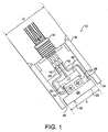
- Figure 1 shows a section through an apparatus according to one embodiment of the present invention.
- the apparatus is a probe 10 for monitoring particles in a fluid stream flowing through a conduit.
- the probe 10 is intended to be flush mounted on an external bend of a pipe 12, as shown in Figure 2 .
- the probe 10 comprises a probe housing 16 within which there is a differential pressure transducer 17 and a detector element 18.
- An electrical connector 19 located at the back of the probe 10 provides an output from the probe 10.
- the detector element 18 comprises a target portion 20 and an acoustic sensing portion 22.
- the detector element 18 is made of the same material as the inside surface of the pipe 12 so that it will corrode in the same way as the pipe 12.
- the target portion 20, the acoustic sensing portion 22, and the transducer 17 are each individually electrically connected to the electrical connector 19 at the rear of the probe 10.
- the electrical connector 19 provides the pressure containment of the probe 10 and is a feedthrough assembly rated for temperature and pressure and chemical compatibility.
- the target portion 20 is located at a front end 24 of the probe 10. Viewed from the front end 24, the probe 10 is circular in cross-section having a diameter D.
- the target portion has a target surface 26 and a back surface 28.
- the target surface 26 is substantially coplanar with the front end 24 of the probe 10, and is circular having a diameter d.
- D is approximately 50 mm and d is approximately 35-40 mm.
- the target portion 20 comprises a sample portion (not shown) that is exposed to corrosive effects of a fluid flow across the target surface 26 of the target portion 20.
- the target portion 20 further comprises a reference portion (not shown) that is protected from the corrosive effects of a fluid flow across the target surface 26 of the target portion 20.
- the target portion 20 has a corrosion sensor (not shown) that is arranged to provide a signal which varies in dependence upon an amount of corrosion of the target portion 20.
- the corrosion sensor is an electrical resistance sensor.
- the sensor is arranged to detect changes in an electrical resistance of the sample portion which result from loss of material of the sample portion due to corrosion. Errors due to temperature and pressure inhomogeneities may be compensated for by additionally detecting changes in an electrical resistance of the reference portion (as the sample portion and the reference portion are subject to the same temperature and pressure effects).
- the sensor is arranged to provide a compensated electrical resistance signal which varies in dependence upon a ratio of the electrical resistance of the sample portion to the electrical resistance of the reference portion.
- the sensor is further arranged to provide a signal which varies in dependence upon a temperature of the reference portion, which is the same as the process temperature T. In particular, the temperature T may be determined from the electrical resistance of the reference portion.
- Such an electrical resistance sensor is described in US Patent No. 6,693,445 (Sutton ), in which the sample portion and the reference portion are electrically connected in series via a bridge and are connected to a current generator which drives current through the series circuit.
- the electronic circuitry further comprises voltage monitoring means arranged to monitor the voltage developed across each of the sample portion and reference portion.
- the sample portion and reference portion of the sensor are situated proximate to each other to help ensure that the temperature difference between the sample portion and the reference portion is minimal and the reference portion has good thermal contact with the environment, such as the fluid in the pipe 12.
- the reference portion may be protected from corrosion by means of a thin protective covering, such as a non-corrosive metallic cover layer made of gold, platinum, chromium, or any other relatively inert metal or other metal which does not corrode to any significant degree when exposed to the fluid in question.
- the electrical resistance sensor may be configured to monitor process temperature T.
- a calibration resistor may be included in the electronic circuitry in series with the sample portion and the reference portion. Such a calibration resistor provides for monitoring the temperature of the target portion 20, and hence the process temperature T of the fluid, without the need for a special temperature sensor.
- the detector element 18 is acoustically decoupled from the pipe 12 and the probe housing 16.
- the acoustic decoupling is accomplished by means of a "pressure-balanced floating arrangement".
- the detector element 18 and the transducer 17 are supported within a sensor housing (not shown).
- the sensor housing is constrained within the probe housing 16 by means of an acoustic decoupling compound (not shown) between the internal wall of the probe housing 16 and an external surface of the sensor housing.
- Further acoustic decoupling is provided by means of a gap 46 between the detector element 18 and the probe housing 16.
- a first connector 40 extends between the electrical connector 19 and the target portion 20.
- a second connector 42 extends between the electrical connector 19 and the acoustic sensing portion 22.
- a third connector 44 extends between the electrical connector 19 and the transducer 17.
- the connectors 40, 42 and 44 are flexible so as to provide sufficient acoustic decoupling from the feed-through connector 19. The "pressure-balanced floating arrangement" therefore provides enough support to prevent vibrations of the detector element 18 and transducer 17, but does not acoustically couple the detector element 18 and transducer 17 to the probe housing 16.
- the acoustic sensing portion 22 is affixed to the back surface 28 of the target portion 20. In a preferred embodiment, the acoustic sensing portion 22 is integrally formed with the target portion 20.
- the acoustic sensing portion 22 comprises a sample acoustic sensor 30 and a reference acoustic sensor 32.
- the two acoustic sensors 30 and 32 are thermally and mechanically balanced within the detector element 18.
- the sample acoustic sensor 30 is acoustically coupled to the detector element 18, whereas the reference acoustic sensor 32 is acoustically decoupled from the detector element 18.
- the acoustic sensors 30 and 32 may be mounted within two distinct chambers.
- the sample acoustic sensor 30 is mounted within oil, whereas a sensitized part of the reference acoustic sensor chamber is nitrogen filled.
- the transducer 17 has a front diaphragm 34 and a back diaphragm 36, and is located behind the acoustic sensing portion 22.
- the front diaphragm 34 is in contact with a back surface 38 of the acoustic sensing portion 22 of the detector element 18.
- the back surface 38 of the acoustic sensing portion 22 is in direct contact with and energised against the front diaphragm 34, but is not sealed.
- the transducer 17 comprises at least one piezoelectric element (not shown).
- fluid and entrained particles travel along the pipe 12 and may impact on the target surface 26 of the target portion 20 of the probe 10.
- an apparatus is a flush probe 10 mounted on an external bend of a pipe 12.
- the probe 10 is mounted at an angle to a predominant flow direction. The mounting angle is dictated by the pipework geometry and anticipated flow regime.
- the probe 10 is positioned flush to the pipe wall to give actual wall thickness loss measurement of the pipe 12.
- non-flush probes may also be provided according alternative embodiments of the present invention (not shown). For example, if it is difficult to mount a probe at a bend (e.g.
- an intrusive probe with an angled head may be used instead.
- Such a probe would protrude within the pipe 12 such that the front face of the detector element would be at an angle of approximately 45° to the predominant flow direction to thereby emulate the conduit surface at the bend (where the corrosion is generally greatest).
- use of a flush probe 10 with a flat target surface 26 is preferred in order to prevent any unnecessary disturbances of the flow regime.
- the fluid and entrained particles are at a process pressure p and process temperature T.
- p may be as high as about 1 ⁇ 10 8 Pa (15,000 psi) and T may be as high as about 180 °C.
- T may be as high as about 180 °C.
- the process temperature T can be measured by sensing the change in electrical resistance of the reference portion of the target portion 20.
- the gap 46 between the detector element 18 and the probe housing 16 allows the fluid flowing within the pipe 12 to enter the space between the probe housing 16 and the combined transducer 17 and detector element 18 arrangement. Nonetheless, the fluid flow rate through this space is negligible compared to the fluid flow rate through the pipe 12, but allows for near instantaneous transfer of heat and pressure.
- the back diaphragm 36 of the transducer 17 is subject only to.the process pressure p and can therefore be used to measure the process pressure.
- the back surface 28 of the target portion 20 is subject to the same process pressure as the target surface 26, and so on, such that the arrangement can be described as "pressure-balanced".
- the pressure-balanced arrangement enables the probe 10 to withstand high temperatures and pressures.
- the pressure-balanced arrangement minimises strain based deflections and thermal gradients of the detector element 18 and thereby reduces potential errors in the acoustic signal and the electrical resistance signal which may otherwise result from strain related distortions of the acoustic sensing portion 22 and the target portion 20.
- the target surface 26 of the target portion 20 is subject to the process pressure p and flow force of the system.
- the front diaphragm 34 of the transducer 17 is coupled to the detector element 18 such that the front diaphragm is subject to the process pressure and flow force of the system.
- the differential pressure between the front diaphragm 34 and the back diaphragm 36 may be used to measure the flow force.
- the detector element 18 Due to the acoustic decoupling of the detector element 18 and the transducer 17 from the housing 16 and the pipe 12, the detector element 18 is not sensitised to detect an unpredictable acoustic noise field related to acoustic signals generated in the vicinity of the associated pipe work and probe housing 16 due to a complex set of fluid flow regimes, particle trajectories and impact responses.
- the acoustic noise detected by the acoustic sensing portion 22 is isolated to the detector element 18 of known characteristics, such that the full spectrum of detected acoustic noise is limited to that which has been transferred from the flowing fluid onto the detector element 18.
- the reference acoustic sensor 32 Since the reference acoustic sensor 32 is located within the acoustic sensing portion 22 of the detector element 18, this sensor 32 is also acoustically decoupled from the housing 16 and the pipe 12. Furthermore, the two acoustic sensors 30 and 32 are identically mounted within the acoustic sensing portion 22 except that the reference acoustic sensor 32 is acoustically decoupled from the detector element 18 (in contrast to the sample acoustic sensor 30 which is acoustically coupled to the detector element 18). Thus, the reference acoustic sensor 32 experiences near identical process temperature and pressure effects which may then be used to compensate for any process induced offset and transient errors of the sample acoustic sensor 30.
- a temperature and pressure compensated acoustic signal may be derived based on the acoustic noise sensed by the two acoustic sensors 30 and 32, and this compensated acoustic signal is related only to the acoustic noise produced on the detector element 18 by the fluid flow and entrained particles impinging on the target surface 26 of the target portion 20 of the detector element 18.
- the compensated acoustic signal is related to a number of key influencing factors such as the acoustic characteristics of target portion 20 (which are known), and the acoustic characteristics of the flow transferring acoustic energy onto the target surface 26.
- the detector element 18 of the probe 10 can be characterised and calibrated for a given set of temperatures and pressures with a range of velocities or flow forces, for various fluid (oil/gas/water) ratios and for various solids entrained in the flow (mass, size and density), and so on.
- the compensated acoustic signal may be analysed in both the time domain and the frequency domain.
- the energy of the compensated acoustic signal is proportional to the mass density events on the target surface 26, and the power is proportional to the rate of change of that energy with respect to time, which is a function of the velocity of the mass densities of the fluid and particles.
- the spectrum of the compensated acoustic signal depends on the types of gas or liquid or solid acting on the target surface 26.
- Flowing gas produces a low amplitude, continuous signal within a frequency range associated with gases.
- Liquids produce a higher amplitude signal than gases (due to their higher density), and the signal is discontinuous and at a higher frequency than a gas signal.
- Solids produce an even higher amplitude signal (dependant on mass and velocity, etc.), but a solid signal is of shorter duration than a liquid signal, and is at a higher frequency again than the liquid signal.
- the analysis of the fluids/solids spectrum is advanced.
- the impact duration time will vary (e.g. dependent on relative hardness of surfaces and impact strength), and the energy converted into acoustic energy will also vary according to the particle mass, velocity and coefficient of restitution of the event.
- These events can be counted and logged according to amplitude and rise time of the compensated acoustic signal, and particle energy may consequently be determined.
- liquids do not generally cause erosion damage (unless, in the limiting velocity, they cause a breakdown of the corrosion durable oxide layer which leads to erosion/corrosion phenomena), whereas solids can be highly erosive compared to liquids.
- the probe 10 simultaneously measures the corrosive and acoustic effects of the events on the same detector element 18.
- the corrosion events in terms of the compensated electrical resistance signal
- the acoustic events in terms of the compensated acoustic signal
- an acoustic event having an uncertain liquid/solid acoustic signature is likely to have been caused by a solid if there is a corresponding corrosive event, but is likely to have been caused by liquid if there is no corresponding corrosive event.
- an apparatus can offer a qualitative indication of fine solids due to their corrosive effect in the absence of an acoustic signal.
- an apparatus offers significant advantages over acoustic detectors and/or electrical resistance probes of the prior art.
- the next step is to qualitatively detect the changes in the flow force acting on the pressure-balanced detector element in order to derive a mean velocity of the fluid stream.
- the differential pressure between the front diaphragm 34 and the back diaphragm 36 of the transducer 17 may be used to measure the flow force on the target surface 26.
- p the effective mass density
- v the fluid velocity
- ⁇ is the angle of incidence of the flow to the target surface 26 of the detector element 18.
- the effective mass density ⁇ is influenced by the compressible fluid density, a function of fluid pressure and temperature, and the volumetric ratio of entrained liquids (oil, condensate, droplets) and solids (particulates).
- R A ⁇ v 2 ⁇ sin ⁇ a ⁇ gas + b ⁇ liquids + c ⁇ solids
- a, b and c are the effective partial volumes of gas, liquids and solids in the fluid stream, liquids and solids are deemed as incompressible
- ⁇ gas is a function of the measured process pressure p and temperature T
- pV nR 0 T.
- the measured flow force R is then converted into mean fluid velocity v .
- the known surface area of the target surface 26 of the detector element 18 can then be used to extrapolate the particle density across the cross section of the pipe 12.
- the derivation of the quantity of particles flowing through the pipe section can be calculated, if it can be assumed the particle density flowing through the pipe 12 is constant. Clearly this assumption cannot be made without an analysis of the flow regime around the probe 10 and the associated pipe work. However this can be overcome by computational fluid modelling to determine the particle trajectory in the vicinity of the probe 10 and a representative model con provide an indication of the particle distribution density.
- an apparatus may be used to determine both the amount of particulate matter in a fluid stream and the corrosive effect of that particulate matter.
- FIG. 3 and 4 An apparatus according to a second embodiment of the present invention is shown schematically in Figures 3 and 4 .
- the apparatus 60 is substantially formed as an open cylinder/ring and is intended to monitor particle impacts, and corrosion and/or erosion events, along a straight section of pipe.
- the apparatus 60 comprises a body portion (not shown) and a detector element 61 having a target surface 62.
- the target surface 62 is substantially flush with an internal surface 64 of a straight section of a pipe 66.
- the target surface 62 is formed as an internal surface of a cylinder/ring.
- the detector element 61 is acoustically decoupled from the body portion and from the pipe 66 by means of an appropriately selected acoustic decoupling material.
- the detector element 61 comprises an acoustic sensor (not shown) that is acoustically coupled to the target surface 62.
- the acoustic sensor is arranged to provide an acoustic signal which varies in dependence upon acoustic noise generated by impacts of particles and fluid on the cylindrical target surface 61.
- the detector element 61 further comprises a corrosion sensor arranged to provide a corrosion signal which varies in dependence upon corrosion and/or erosion of the target surface.
- the corrosion sensor is an electrical resistance sensor.
- Figure 4 shows a section through the arrangement of Figure 3 along line AA'.
- the detector element 61 and the target surface 62 comprise a plurality of sectors 68 for the purpose of monitoring corrosion and/or erosion.
- Figure 4 depicts six sectors 68 that each extend along the full longitudinal length L of the cylindrical target surface 62.
- the sectors 68 each extend along a respective circumferential portion of the target surface 62.
- the sectors 68 each extend along a respective 60 degree portion of the cylindrical target surface 62.
- the boundaries between the sectors 68 define pick-off points 70 where the detector portion is connected to the electronic circuitry to measure electrical resistance. In this way, it is possible to monitor the electrical resistance in each sector 68, and hence the corrosion and/or erosion in each sector 68.
- this may be indicative of an anomalous flow regime in that section of pipe, e.g. due to a partial blockage upstream.
- the sectors 68 are acoustically coupled, so only one acoustic sensor is required, but this single acoustic sensor cannot differentiate between particle impacts occurring in different sectors 68.
- Figure 5 shows an arrangement including both the flush probe 10 of Figure 1 and the cylindrical apparatus 60 of Figure 3 to monitor particles in a fluid stream within a single section of pipe 80.
- Choke valves are used to choke back the flow in oil and gas production flow streams. Choke valves in wellheads tend to fail due to erosion, corrosion, cavitation and vibration caused by sand particles.
- the choke valve stem i.e. the shaft that is adjusted up and down to change the extent of choking back the flow
- the choke valve stem can get damaged by the sand at high flow rates.
- the flow jets become unstable and create "preferential flow” (i.e. a highly concentrated high velocity jet with entrained particles) at the outlet from the valve. This preferential flow results in very high localised erosion and corrosion/erosion rates at the outlet of the valve which indicate that the choke valve is failing.
- the preferential flow would generate an amplified acoustic signal at the cylindrical apparatus 60 due to the much higher velocity, increased angle of impingement and increased number of particles hitting the target surface 62.
- an amplified acoustic signal on the target surface 62 could be due to more sand or to preferential flow. Therefore, the probe 10 downstream of the apparatus 60 is used to determine the present corrosion and acoustic signatures of the flow, which can then be correlated with the corrosion and acoustic signals from the apparatus 60.
- such an arrangement can be used as a choke valve condition monitor.
- such an arrangement would inform the operator of the historical performance of the choke (i.e. this amount of sand at this velocity with this erosion characteristic created this life expectancy of the choke).
Description
- The present invention relates to an apparatus for monitoring particles in a fluid stream, and to a method of monitoring particles in a fluid stream. In particular, the present invention relates to monitoring sand in oil and gas production flow streams.
- It is desirable to be able to monitor particles in a fluid flowing through a conduit. It is particularly desirable to be able to monitor formation sand that is entrained in oil and gas production flow streams. In such systems, the particles may influence erosion, erosion/corrosion and/or corrosion of the conduit surface, potentially leading to breaches of the conduit by the fluid. Therefore, it is important to be able to measure the metal loss of the conduit surface, especially at conduit bends where the metal loss rate is greatest. Nonetheless, it is also important to monitor metal loss on straight sections of a conduit. (It should be noted that, in the art, "corrosion" is a broad term encompassing all types of surface metal loss, including erosion and erosion/corrosion.)
- Conventionally, the corrosion of such a conduit surface is measured, for example, by an electrical resistance probe. Such a probe has a sample element that is exposed to the fluid flow such that particles entrained in the fluid flow may impact the sample element. When a particle impacts the sample element in this way, it may corrode the sample element and therefore change the thickness and hence the electrical resistance of the sample element. An electrical resistance probe therefore measures changes in the electrical resistance of its sample element in order to determine the corrosion rate.
- A prior art electrical resistance probe is described, for example, in
US Patent No. 6,693,445 (Sutton ). In this patent, a probe is disclosed which is suitable for use with an apparatus for monitoring the corrosion of a material by accurately measuring changes in the resistance of an exposed sample element in relation to a protected reference element. The two elements are electrically connected in series via a bridge. The elements are formed from the same piece of material divided by an elongate slot and are proximate to one another so that the temperature difference between them is minimal. This prevents false indications of corrosion by ensuring that the temperature coefficient of the resistivities is the same in both elements. The reference element is covered with a corrosion-resistant layer. This layer is preferably as thin as possible and also a good thermal conductor to further ensure equal temperature of the reference and exposed elements. - Another prior art electrical resistance detector is described in
US Patent No. 6,946,855 (Hemblade ), in which an apparatus is disclosed for monitoring the effect on a material of exposure to a fluid, and thereby monitoring the effect on a section of pipe for carrying the fluid. The apparatus includes a sensor element exposed to the fluid and formed as a ring of the material coaxially mounted within, but electrically insulated from, the section of pipe. Changes in the electrical resistance of the sensor element are monitored. Preferably, the apparatus also includes a reference element electrically insulated from the pipe, electrically connected in series to the sensor element and protected from exposure to the fluid. The elements may both be made from the same material as the pipe and, as they are contained within it, experience the same temperature and pressure variations as the pipe. In this manner a change in the resistance of the sensor element caused by corrosion/erosion by the fluid accurately indicates the degree of corrosion/erosion of the pipe carrying the fluid. - In addition to corrosion, excessive numbers of particles entrained in a fluid may cause blockage of the fluid flow through the conduit. Therefore, it is also important to measure the amount of particulate matter entrained in a given fluid stream and correlate this quantity to corrosion.
- In the past, the amount of particulate matter has often been estimated based on the measured corrosion rate. However, some particle impacts may not cause corrosion due to insufficient energy and/or a combination of mechanical properties of both particle and surface, potentially transferring all impulse momentum into the elastic region of the material, hence resulting in no permanent deformation or damage of the impacted surface. Or conversely, particulate matter of low mass but high hardness and sharp edges can cause high corrosion rates. Methods to overcome this have been to use softer element materials but such materials are not representative of the pipe, and therefore cannot be used to measure the extent of actual pipe corrosion. A range of particle size, shape and mechanical properties will potentially give different corrosion rates. In addition the particle velocity will affect the corrosion rate, which is another reason that the particle mass is not easy to determine from the corrosion rate alone. Furthermore, the particle velocity is generally determined from another source, and is not representative of the particle velocity at the sensor itself, which introduces further errors. All these factors undermine the possibility of corrosion measurements alone to determine particle mass flowing through a system.
- For this reason, the amount of particulate matter entrained in a fluid stream has previously been calculated using a separate acoustic sensor which measures the acoustic noise on the external surface of the conduit. Such an acoustic sensor is often used in addition to an electrical resistance type probe described above. According to the acoustic sensor technique, as a given particle impacts a surface it will give up some of its kinetic energy in the form of impact energy and will produce a surface acoustic emission. An acoustic sensor is therefore positioned to detect these emissions on the external surface of a pipe. The acoustic emission amplitude and frequency response will depend on a number of variables such as where the sensor is situated (e.g. a bend), the flow regime, gas/oil ratios, trajectory of the entrained particles, number of rebounds, and the extent of internal surface area subjected to impact. However, the acoustic noise measured by such a detector will also be contaminated by flow noise and noises from outside the conduit. Methods are employed to separate flow noise and particle impact noise by the means of measuring the frequency response distribution using selective analogue and digital filtering, but these methods are not perfect. In particular, there can be a close overlap of the acoustic signatures of liquids and solids in some situations. Furthermore, very small particles (i.e. "fines" having a dimension less than 25 microns) will go undetected by such a probe because they tend not to create acoustic signals of sufficient amplitude to be detected. In an attempt to overcome some of these problems, the external acoustic sensor is calibrated in situ by injecting sand to characterise the location. However this is costly and impractical, especially in sub-sea locations and potentially introduces unwanted damage during the calibration process. In order to quantify the amount of sand, the particle velocity is again required, since the acoustic energy will depend on both the mass of the particle and the velocity of the particle at the impacted surface. As described above, the particle velocity is generally determined from another source, and is not representative of the particle velocity at the sensor itself, which introduces further errors.
- In
US 5681986 , an improved invasive acoustic sensor apparatus detects particulate matter in a flow by impingement thereon. The apparatus includes an axially extending probe body having an active length positionable in a flow and a distributed piezoelectric transducer disposed therein. The transducer is acoustically coupled to an interior surface of the body, along substantially the entire active length thereof, and may be a piezoelectric film, piezoelectric tube, or a plurality of electrically parallel connected piezoelectric tube elements. The apparatus further includes an acoustic isolation layer disposed between the probe body and positioning structure to reduce transmission of process wall vibration to the transducer. - In
GB 2408100 -
EP 0483578 describes a procedure for detecting particles in a fluid stream, comprising utilizing one or more probes provided with at least one measuring element or erosion element. The probe is placed in a fluid stream, and the particle content is quantitatively determined by measuring changes of electrical resistance as a function of erosion of the measuring element by contact with particles moving in the stream. The probe may be equipped with a measuring head having a V-like shape directed upstream, and the two planar surfaces defined by the V-like shape may each be equipped with one or more measuring elements. - The present invention aims to address these and other such problems with the art by providing a more accurate and versatile apparatus for monitoring particles in a fluid stream flowing through a conduit.
- According to a first aspect of the present invention, there is provided an apparatus for monitoring particles in a fluid stream. The apparatus comprises a housing and a detector element with the housing. The detector element is acoustically decoupled from the housing. The detector element comprises a target surface, a sample acoustic sensor and a corrosion sensor. The sample acoustic sensor is acoustically coupled to the target surface. The sample acoustic sensor is arranged to provide a first signal which varies in dependence upon acoustic noise generated by impacts of particles and fluid on the target surface. The corrosion sensor is arranged to provide a second signal which varies in dependence upon an electrical resistance of the detector element, the electrical resistance of the detector element being related to the corrosion and/or erosion of the target surface.
- Such an apparatus is able to monitor the quantity of particulate matter in a fluid stream as well as the corrosive effects of that particulate matter, such as the erosion rate and the amount of erosion. Furthermore, because the apparatus monitors corrosion and acoustic noise on the same target surface, this enables more accurate differentiation between liquid and solid impact events since the events may be analysed in terms of both their acoustic and corrosive signatures.
- Preferably, the detector element is pressure-balanced. More preferably, fluid may flow around substantially the whole detector element thereby pressure balancing the detector element.
- Preferably, the detector element comprises a sample portion that is corrodible and/or erodible by particles impacting on the target surface, the second signal varying in dependence upon an electrical resistance of the sample portion. More preferably, the detector element further comprises a reference portion that is not corrodible and/or erodible by particles impacting on the target surface, and the second signal varies in dependence upon a ratio of the electrical resistance of the sample portion to an electrical resistance of the reference portion.
- In another preferred embodiment, the apparatus further comprises temperature measurement means arranged to provide a signal which varies in dependence upon. More preferably again, the temperature measurement means is arranged to provide a signal which varies in dependence upon a temperature of the reference portion.
- In yet another preferred embodiment, the detector element further comprises a reference acoustic sensor that is acoustically decoupled from the housing and the target surface, the reference acoustic sensor being arranged to provide a signal which varies in dependence upon acoustic noise detected by the reference acoustic sensor.
- In a further preferred embodiment, the apparatus further comprises pressure measurement means arranged to provide a signal which varies in dependence upon a pressure of the fluid stream.
- In a still further preferred embodiment, the apparatus further comprises flow force measurement means arranged to provide a signal which varies in dependence upon a flow force of the fluid stream on the target surface.
- Preferably, the pressure measurement means and the flow force measurement means together comprise a differential pressure transducer. More preferably, at least one of the pressure measurement means and the flow force measurement means comprises a piezoelectric element.
- Preferably, the target surface comprises a plurality of target surface sections, the corrosion sensor being arranged to provide a plurality of corrosive signals, each corrosive signal varying in dependence upon corrosion and/or erosion of a respective target surface section.
- In a preferred embodiment, the target surface is substantially planar. More preferably, the target surface is mounted at an angle to a predominant flow direction.
- In an alternative embodiment, the target surface lies within a surface of a cylinder.
- There is also provided a choke valve condition monitor for monitoring the condition of a choke valve in a pipe. The monitor comprises a first apparatus (as described above) mounted downstream of the choke valve such that the first and second signals of the first apparatus are condition signals which vary in dependence upon a flow regime at an outlet from the choke valve. The target surface of the first apparatus lies at an internal surface of the pipe. The monitor further comprises a second apparatus (as described above) mounted downstream of the first apparatus such that the first and second signals of the second apparatus are reference signals relating to acoustic and corrosive and/or erosive signatures of particles in the fluid stream. The monitor additionally comprises an output arranged to provide an output signal which varies in dependence upon the condition signals and the reference signals in order to provide an indication of choke valve condition.
- There is also provided a method of monitoring the condition of a choke valve in a pipe. The method comprises providing a first apparatus (as described above) mounted downstream of the choke valve such that the first and second signals of the first apparatus are condition signals which vary in dependence upon a flow regime at an outlet from the choke valve. The target surface of the first apparatus lies at an internal surface of the pipe. The method further comprises providing a second apparatus (as described above) mounted downstream of the first apparatus such that the first and second signals of the second apparatus are reference signals relating to acoustic and corrosive and/or erosive signatures of particles in the fluid stream. The method additionally comprises comparing the condition signals and the reference signals in order to provide an indication of choke valve condition.
- According to a second aspect of the present invention, there is provided a method of monitoring particles in a fluid stream, comprising: providing an apparatus having a housing and a detector element within the housing, the detector element being acoustically decoupled from the body portion, and the detector element having a target surface; measuring acoustic noise generated by impacts of particles and fluid on the target surface; and measuring corrosion and/or erosion of the target surface by measuring an electrical resistance of the detector element, the electrical resistance of the detector element being related to the corrosion and/or erosion of the target surface.
- In a preferred embodiment, the method further comprises measuring a flow force of the fluid stream on the target surface. In another preferred embodiment, the method further comprises measuring a pressure of the fluid stream. In yet another preferred embodiment, the method further comprises measuring a temperature of the fluid stream.
- Preferably, the method further comprises correlating the measured acoustic noise and the measured corrosion and/or erosion. More preferably, the measured pressure, temperature, and/or flow force may also be correlated with the measured acoustic noise and the measured corrosion and/or erosion.
- Other preferred features of the present invention are set out in the appended claims.
- Embodiments of the present invention will now be described by way of example with reference to the accompanying drawings in which:
-
Figure 1 is a section through an apparatus according to one embodiment of the present invention; -
Figure 2 shows the apparatus ofFigure 1 mounted on a bend of a pipe; -
Figure 3 is a schematic representation of an apparatus according to a second embodiment of the present invention mounted on a straight section of a pipe; -
Figure 4 is a section through the apparatus ofFigure 3 along line AA'; and -
Figure 5 shows an arrangement including the apparatus ofFigure 1 and the apparatus ofFigure 3 within a single section of pipe. -
Figure 1 shows a section through an apparatus according to one embodiment of the present invention. InFigure 1 the apparatus is aprobe 10 for monitoring particles in a fluid stream flowing through a conduit. Theprobe 10 is intended to be flush mounted on an external bend of apipe 12, as shown inFigure 2 . Thus there is anopening 14 in thepipe 12 through which theprobe 10 is inserted. - Referring to
Figure 1 , theprobe 10 comprises aprobe housing 16 within which there is adifferential pressure transducer 17 and adetector element 18. Anelectrical connector 19 located at the back of theprobe 10 provides an output from theprobe 10. Thedetector element 18 comprises atarget portion 20 and anacoustic sensing portion 22. In a preferred embodiment, thedetector element 18 is made of the same material as the inside surface of thepipe 12 so that it will corrode in the same way as thepipe 12. Thetarget portion 20, theacoustic sensing portion 22, and thetransducer 17 are each individually electrically connected to theelectrical connector 19 at the rear of theprobe 10. Theelectrical connector 19 provides the pressure containment of theprobe 10 and is a feedthrough assembly rated for temperature and pressure and chemical compatibility. - The
target portion 20 is located at afront end 24 of theprobe 10. Viewed from thefront end 24, theprobe 10 is circular in cross-section having a diameter D. The target portion has atarget surface 26 and aback surface 28. Thetarget surface 26 is substantially coplanar with thefront end 24 of theprobe 10, and is circular having a diameter d. Thus a front surface area of thetarget portion 20 is known. In a preferred embodiment, D is approximately 50 mm and d is approximately 35-40 mm. - The
target portion 20 comprises a sample portion (not shown) that is exposed to corrosive effects of a fluid flow across thetarget surface 26 of thetarget portion 20. Thetarget portion 20 further comprises a reference portion (not shown) that is protected from the corrosive effects of a fluid flow across thetarget surface 26 of thetarget portion 20. Thetarget portion 20 has a corrosion sensor (not shown) that is arranged to provide a signal which varies in dependence upon an amount of corrosion of thetarget portion 20. - In a preferred embodiment, the corrosion sensor is an electrical resistance sensor. Thus, the sensor is arranged to detect changes in an electrical resistance of the sample portion which result from loss of material of the sample portion due to corrosion. Errors due to temperature and pressure inhomogeneities may be compensated for by additionally detecting changes in an electrical resistance of the reference portion (as the sample portion and the reference portion are subject to the same temperature and pressure effects). Thus, for the purposes of temperature and pressure compensation, the sensor is arranged to provide a compensated electrical resistance signal which varies in dependence upon a ratio of the electrical resistance of the sample portion to the electrical resistance of the reference portion. In a preferred embodiment, the sensor is further arranged to provide a signal which varies in dependence upon a temperature of the reference portion, which is the same as the process temperature T. In particular, the temperature T may be determined from the electrical resistance of the reference portion.
- Such an electrical resistance sensor is described in
US Patent No. 6,693,445 (Sutton ), in which the sample portion and the reference portion are electrically connected in series via a bridge and are connected to a current generator which drives current through the series circuit. The electronic circuitry further comprises voltage monitoring means arranged to monitor the voltage developed across each of the sample portion and reference portion. The sample portion and reference portion of the sensor are situated proximate to each other to help ensure that the temperature difference between the sample portion and the reference portion is minimal and the reference portion has good thermal contact with the environment, such as the fluid in thepipe 12. The reference portion may be protected from corrosion by means of a thin protective covering, such as a non-corrosive metallic cover layer made of gold, platinum, chromium, or any other relatively inert metal or other metal which does not corrode to any significant degree when exposed to the fluid in question. The electrical resistance sensor may be configured to monitor process temperature T. A calibration resistor may be included in the electronic circuitry in series with the sample portion and the reference portion. Such a calibration resistor provides for monitoring the temperature of thetarget portion 20, and hence the process temperature T of the fluid, without the need for a special temperature sensor. - The
detector element 18 is acoustically decoupled from thepipe 12 and theprobe housing 16. In the embodiment ofFigures 1 and2 , the acoustic decoupling is accomplished by means of a "pressure-balanced floating arrangement". In this arrangement, thedetector element 18 and thetransducer 17 are supported within a sensor housing (not shown). The sensor housing is constrained within theprobe housing 16 by means of an acoustic decoupling compound (not shown) between the internal wall of theprobe housing 16 and an external surface of the sensor housing. Further acoustic decoupling is provided by means of agap 46 between thedetector element 18 and theprobe housing 16. Afirst connector 40 extends between theelectrical connector 19 and thetarget portion 20. Asecond connector 42 extends between theelectrical connector 19 and theacoustic sensing portion 22. Athird connector 44 extends between theelectrical connector 19 and thetransducer 17. Theconnectors connector 19. The "pressure-balanced floating arrangement" therefore provides enough support to prevent vibrations of thedetector element 18 andtransducer 17, but does not acoustically couple thedetector element 18 andtransducer 17 to theprobe housing 16. - The
acoustic sensing portion 22 is affixed to theback surface 28 of thetarget portion 20. In a preferred embodiment, theacoustic sensing portion 22 is integrally formed with thetarget portion 20. Theacoustic sensing portion 22 comprises a sampleacoustic sensor 30 and a referenceacoustic sensor 32. The twoacoustic sensors detector element 18. The sampleacoustic sensor 30 is acoustically coupled to thedetector element 18, whereas the referenceacoustic sensor 32 is acoustically decoupled from thedetector element 18. In particular, theacoustic sensors acoustic sensor 30 is mounted within oil, whereas a sensitized part of the reference acoustic sensor chamber is nitrogen filled. - The
transducer 17 has afront diaphragm 34 and aback diaphragm 36, and is located behind theacoustic sensing portion 22. In a preferred embodiment, thefront diaphragm 34 is in contact with aback surface 38 of theacoustic sensing portion 22 of thedetector element 18. Theback surface 38 of theacoustic sensing portion 22 is in direct contact with and energised against thefront diaphragm 34, but is not sealed. Thetransducer 17 comprises at least one piezoelectric element (not shown). - In use, fluid and entrained particles travel along the
pipe 12 and may impact on thetarget surface 26 of thetarget portion 20 of theprobe 10. - The
probe 10 should be located such that there is a high incident rate of particles impacting on thetarget surface 26. Therefore, as shown inFigure 2 , an apparatus according to a preferred embodiment of the present invention is aflush probe 10 mounted on an external bend of apipe 12. By flush mounting theprobe 10 on an external bend of thepipe 12, theprobe 10 is mounted at an angle to a predominant flow direction. The mounting angle is dictated by the pipework geometry and anticipated flow regime. Furthermore, theprobe 10 is positioned flush to the pipe wall to give actual wall thickness loss measurement of thepipe 12. However, it will be understood that non-flush probes may also be provided according alternative embodiments of the present invention (not shown). For example, if it is difficult to mount a probe at a bend (e.g. due to space constraints), then an intrusive probe with an angled head may be used instead. Such a probe would protrude within thepipe 12 such that the front face of the detector element would be at an angle of approximately 45° to the predominant flow direction to thereby emulate the conduit surface at the bend (where the corrosion is generally greatest). However, use of aflush probe 10 with aflat target surface 26 is preferred in order to prevent any unnecessary disturbances of the flow regime. - The fluid and entrained particles are at a process pressure p and process temperature T. In an oil and gas production flow stream, p may be as high as about 1×10⁸ Pa (15,000 psi) and T may be as high as about 180 °C. Thus, the
probe 10 is built to withstand temperatures and pressures of this magnitude. - As discussed above, the process temperature T can be measured by sensing the change in electrical resistance of the reference portion of the
target portion 20. - The
gap 46 between thedetector element 18 and theprobe housing 16 allows the fluid flowing within thepipe 12 to enter the space between theprobe housing 16 and the combinedtransducer 17 anddetector element 18 arrangement. Nonetheless, the fluid flow rate through this space is negligible compared to the fluid flow rate through thepipe 12, but allows for near instantaneous transfer of heat and pressure. Thus, theback diaphragm 36 of thetransducer 17 is subject only to.the process pressure p and can therefore be used to measure the process pressure. - Due to the floating arrangement of the
detector element 18, theback surface 28 of thetarget portion 20 is subject to the same process pressure as thetarget surface 26, and so on, such that the arrangement can be described as "pressure-balanced". The pressure-balanced arrangement enables theprobe 10 to withstand high temperatures and pressures. - Furthermore, the pressure-balanced arrangement minimises strain based deflections and thermal gradients of the
detector element 18 and thereby reduces potential errors in the acoustic signal and the electrical resistance signal which may otherwise result from strain related distortions of theacoustic sensing portion 22 and thetarget portion 20. - The
target surface 26 of thetarget portion 20 is subject to the process pressure p and flow force of the system. Thefront diaphragm 34 of thetransducer 17 is coupled to thedetector element 18 such that the front diaphragm is subject to the process pressure and flow force of the system. Thus, the differential pressure between thefront diaphragm 34 and theback diaphragm 36 may be used to measure the flow force. - Due to the acoustic decoupling of the
detector element 18 and thetransducer 17 from thehousing 16 and thepipe 12, thedetector element 18 is not sensitised to detect an unpredictable acoustic noise field related to acoustic signals generated in the vicinity of the associated pipe work and probehousing 16 due to a complex set of fluid flow regimes, particle trajectories and impact responses. Thus, the acoustic noise detected by theacoustic sensing portion 22 is isolated to thedetector element 18 of known characteristics, such that the full spectrum of detected acoustic noise is limited to that which has been transferred from the flowing fluid onto thedetector element 18. - Since the reference
acoustic sensor 32 is located within theacoustic sensing portion 22 of thedetector element 18, thissensor 32 is also acoustically decoupled from thehousing 16 and thepipe 12. Furthermore, the twoacoustic sensors acoustic sensing portion 22 except that the referenceacoustic sensor 32 is acoustically decoupled from the detector element 18 (in contrast to the sampleacoustic sensor 30 which is acoustically coupled to the detector element 18). Thus, the referenceacoustic sensor 32 experiences near identical process temperature and pressure effects which may then be used to compensate for any process induced offset and transient errors of the sampleacoustic sensor 30. Hence, a temperature and pressure compensated acoustic signal may be derived based on the acoustic noise sensed by the twoacoustic sensors detector element 18 by the fluid flow and entrained particles impinging on thetarget surface 26 of thetarget portion 20 of thedetector element 18. - The compensated acoustic signal is related to a number of key influencing factors such as the acoustic characteristics of target portion 20 (which are known), and the acoustic characteristics of the flow transferring acoustic energy onto the
target surface 26. Thedetector element 18 of theprobe 10 can be characterised and calibrated for a given set of temperatures and pressures with a range of velocities or flow forces, for various fluid (oil/gas/water) ratios and for various solids entrained in the flow (mass, size and density), and so on. - The compensated acoustic signal may be analysed in both the time domain and the frequency domain.
- In the time domain, the energy of the compensated acoustic signal is proportional to the mass density events on the
target surface 26, and the power is proportional to the rate of change of that energy with respect to time, which is a function of the velocity of the mass densities of the fluid and particles. - In the frequency domain, the spectrum of the compensated acoustic signal depends on the types of gas or liquid or solid acting on the
target surface 26. Flowing gas produces a low amplitude, continuous signal within a frequency range associated with gases. Liquids produce a higher amplitude signal than gases (due to their higher density), and the signal is discontinuous and at a higher frequency than a gas signal. Solids produce an even higher amplitude signal (dependant on mass and velocity, etc.), but a solid signal is of shorter duration than a liquid signal, and is at a higher frequency again than the liquid signal. - Having identified a means to partition the compensated acoustic signal in both the time and frequency domains, the analysis of the fluids/solids spectrum is advanced. When a solid impacts the
target surface 26, the impact duration time will vary (e.g. dependent on relative hardness of surfaces and impact strength), and the energy converted into acoustic energy will also vary according to the particle mass, velocity and coefficient of restitution of the event. These events can be counted and logged according to amplitude and rise time of the compensated acoustic signal, and particle energy may consequently be determined. - There can be a close overlap of the acoustic characteristics of liquids and solids, so the associated acoustic responses can easily be confused in some situations, resulting in potentially higher estimates of solids content. Furthermore, in high velocity liquid/gas mixtures, fine mists can cause spectra similar to fine solids, or, conversely, larger droplets can cause acoustic signals similar to softer solids.
- However, it is known that liquids do not generally cause erosion damage (unless, in the limiting velocity, they cause a breakdown of the corrosion durable oxide layer which leads to erosion/corrosion phenomena), whereas solids can be highly erosive compared to liquids.
- According to an embodiment of the present invention, the
probe 10 simultaneously measures the corrosive and acoustic effects of the events on thesame detector element 18. Thus, the corrosion events (in terms of the compensated electrical resistance signal) may be correlated with the acoustic events (in terms of the compensated acoustic signal) to resolve any ambiguities in the liquid/solid acoustic spectrum. For example, an acoustic event having an uncertain liquid/solid acoustic signature is likely to have been caused by a solid if there is a corresponding corrosive event, but is likely to have been caused by liquid if there is no corresponding corrosive event. - In addition, very small solid particles (i.e. "fines" having a dimension less than 25 microns) tend not to create acoustic signals of sufficient amplitude to be detected. Therefore, these fines would not be detected by an acoustic sensor alone. However, fines can still produce corrosive effects. Therefore, an apparatus according to an embodiment of the present invention can offer a qualitative indication of fine solids due to their corrosive effect in the absence of an acoustic signal.
- Hence, an apparatus according to an embodiment of the present invention offers significant advantages over acoustic detectors and/or electrical resistance probes of the prior art.
- Having identified the energy/power of the acoustic signals impacting the
target surface 26, and having characterised the gas, liquid and solids profiles by acoustic spectra and corrosion measurements, and having counted the impact events according to rise time and amplitude, the mass of a particle is still unknown without knowledge of the velocity of the fluid/particle. Therefore, the next step is to qualitatively detect the changes in the flow force acting on the pressure-balanced detector element in order to derive a mean velocity of the fluid stream. - As described above, the differential pressure between the
front diaphragm 34 and theback diaphragm 36 of thetransducer 17 may be used to measure the flow force on thetarget surface 26. The flow force R may be written as:
where p is the effective mass density, A is the area of the target surface 26 (i.e. A=π(d/2)2 ), v is the fluid velocity, and θ is the angle of incidence of the flow to thetarget surface 26 of thedetector element 18. The effective mass density ρ is influenced by the compressible fluid density, a function of fluid pressure and temperature, and the volumetric ratio of entrained liquids (oil, condensate, droplets) and solids (particulates). Then:
where a, b and c are the effective partial volumes of gas, liquids and solids in the fluid stream, liquids and solids are deemed as incompressible, and ρgas is a function of the measured process pressure p and temperature T, and pV=nR0T. - The measured flow force R is then converted into mean fluid velocity v. The mean fluid velocity v may be used with the particle energy equation (E = (1/2)mv2 ) to derive the cumulative mass rate of the particles with corrections for liquid signals using the corrosion detection signal (i.e. the compensated electrical resistance signal).
- The known surface area of the
target surface 26 of thedetector element 18 can then be used to extrapolate the particle density across the cross section of thepipe 12. The derivation of the quantity of particles flowing through the pipe section can be calculated, if it can be assumed the particle density flowing through thepipe 12 is constant. Clearly this assumption cannot be made without an analysis of the flow regime around theprobe 10 and the associated pipe work. However this can be overcome by computational fluid modelling to determine the particle trajectory in the vicinity of theprobe 10 and a representative model con provide an indication of the particle distribution density. - Having identified the flow characteristics in terms of temperature and pressure, with a qualitative indication of changes of flow velocity we are able to characterise the flow in terms of gas, non-erosive liquids and solids content. By correlating acoustic energy signals in the solids spectrum with flow velocity and assuming constant mass density it is possible to derive particle numbers in a range of particle sizes. In this way, the particle size spectrum is correlated with the corresponding particle erosiveness for a given velocity profile under the pressure and temperature conditions. Hence, we not only derive the particle mass, size and solids production rate profile of the reservoir under the changing operating conditions and the corresponding erosive damage in that actual location, but we also gain a profile of the potential cumulative amount of erosion damage elsewhere in the system exposed to similar trajectories.
- Thus, an apparatus according to an embodiment of the present invention may be used to determine both the amount of particulate matter in a fluid stream and the corrosive effect of that particulate matter.
- An apparatus according to a second embodiment of the present invention is shown schematically in
Figures 3 and 4 . In this embodiment, theapparatus 60 is substantially formed as an open cylinder/ring and is intended to monitor particle impacts, and corrosion and/or erosion events, along a straight section of pipe. - The
apparatus 60 comprises a body portion (not shown) and adetector element 61 having atarget surface 62. Thetarget surface 62 is substantially flush with aninternal surface 64 of a straight section of apipe 66. Thus, thetarget surface 62 is formed as an internal surface of a cylinder/ring. - The
detector element 61 is acoustically decoupled from the body portion and from thepipe 66 by means of an appropriately selected acoustic decoupling material. Thedetector element 61 comprises an acoustic sensor (not shown) that is acoustically coupled to thetarget surface 62. The acoustic sensor is arranged to provide an acoustic signal which varies in dependence upon acoustic noise generated by impacts of particles and fluid on thecylindrical target surface 61. Thedetector element 61 further comprises a corrosion sensor arranged to provide a corrosion signal which varies in dependence upon corrosion and/or erosion of the target surface. The corrosion sensor is an electrical resistance sensor. - It is also possible to incorporate a reference acoustic sensor and a reference corrosion sensor into the
apparatus 60 to compensate for temperature and pressure inhomogeneities (see the description above relating to the reference portion and sample portion of the embodiment ofFigures 1 and2 ). -
Figure 4 shows a section through the arrangement ofFigure 3 along line AA'. In a preferred embodiment, thedetector element 61 and thetarget surface 62 comprise a plurality ofsectors 68 for the purpose of monitoring corrosion and/or erosion.Figure 4 depicts sixsectors 68 that each extend along the full longitudinal length L of thecylindrical target surface 62. Thesectors 68 each extend along a respective circumferential portion of thetarget surface 62. InFigure 4 , thesectors 68 each extend along a respective 60 degree portion of thecylindrical target surface 62. The boundaries between thesectors 68 define pick-offpoints 70 where the detector portion is connected to the electronic circuitry to measure electrical resistance. In this way, it is possible to monitor the electrical resistance in eachsector 68, and hence the corrosion and/or erosion in eachsector 68. Thus, if there is a different amount of erosion in each sector, this may be indicative of an anomalous flow regime in that section of pipe, e.g. due to a partial blockage upstream. - A corrosion sensor having sectors as described above is disclosed in
US Patent No. 6,946,855 (Hemblade ). - The
sectors 68 are acoustically coupled, so only one acoustic sensor is required, but this single acoustic sensor cannot differentiate between particle impacts occurring indifferent sectors 68. -
Figure 5 shows an arrangement including both theflush probe 10 ofFigure 1 and thecylindrical apparatus 60 ofFigure 3 to monitor particles in a fluid stream within a single section ofpipe 80. - Let us assume that both detectors are simultaneously being used to monitor particles in the fluid stream, and that the acoustic and corrosion measurements from each of these detectors remain approximately constant and the ratio of these measurements remains approximately constant. If the measurements from the
flush probe 10 continue to remain constant while the measurements from thecylindrical apparatus 60 start to vary, this is likely to be indicative of a change of flow regime, rather than a change in the quantity/qualities of the particulate matter in the fluid stream. - One application of this arrangement would be as a choke valve condition monitor. Choke valves are used to choke back the flow in oil and gas production flow streams. Choke valves in wellheads tend to fail due to erosion, corrosion, cavitation and vibration caused by sand particles. The choke valve stem (i.e. the shaft that is adjusted up and down to change the extent of choking back the flow) can get damaged by the sand at high flow rates. When the stem gets damage, the flow jets become unstable and create "preferential flow" (i.e. a highly concentrated high velocity jet with entrained particles) at the outlet from the valve. This preferential flow results in very high localised erosion and corrosion/erosion rates at the outlet of the valve which indicate that the choke valve is failing.
- Let us assume that there is a choke valve positioned near point B in
Figure 5 , slightly upstream of thecylindrical apparatus 60, which is itself slightly upstream of a bend in thepipe 80 where theflush probe 10 is mounted. - Prior to generating a large (and damaging) erosive signal, the preferential flow would generate an amplified acoustic signal at the
cylindrical apparatus 60 due to the much higher velocity, increased angle of impingement and increased number of particles hitting thetarget surface 62. - Of course, an amplified acoustic signal on the
target surface 62 could be due to more sand or to preferential flow. Therefore, theprobe 10 downstream of theapparatus 60 is used to determine the present corrosion and acoustic signatures of the flow, which can then be correlated with the corrosion and acoustic signals from theapparatus 60. - Thus, such an arrangement can be used as a choke valve condition monitor. In addition, such an arrangement would inform the operator of the historical performance of the choke (i.e. this amount of sand at this velocity with this erosion characteristic created this life expectancy of the choke).
- Although preferred embodiments of the invention have been described, it is to be understood that these are by way of example only and that various modifications may be contemplated.
Claims (15)
- An apparatus (10) for monitoring particles in a fluid stream, comprising:a housing (16); anda detector element (18) within the housing, the detector element being acoustically decoupled from the housing, the detector element comprising:a target surface (26);a sample acoustic sensor (30) that is acoustically coupled to the target surface, the sample acoustic sensor being arranged to provide a first signal which varies in dependence upon acoustic noise generated by impacts of particles and fluid on the target surface; anda corrosion sensor arranged to provide a second signal which varies in dependence upon an electrical resistance of the detector element, the electrical resistance of the detector element being related to the corrosion and/or erosion of the target surface.
- The apparatus of claim 1 in which the detector element comprises a sample portion that is corrodible and/or erodible by particles impacting on the target surface, the second signal varying in dependence upon an electrical resistance of the sample portion.
- The apparatus of claim 2 in which the detector element further comprises a reference portion that is not corrodible and/or erodible by particles impacting on the target surface, and the second signal varies in dependence upon a ratio of the electrical resistance of the sample portion to an electrical resistance of the reference portion.
- The apparatus of any preceding claim further comprising temperature measurement means arranged to provide a signal which varies in dependence upon the temperature of the fluid stream.
- The apparatus of claim 4 when dependent on claim 3 in which the temperature measurement means is arranged to provide a signal which varies in dependence upon a temperature of the reference portion.
- The apparatus of any preceding claim in which the detector element further comprises a reference acoustic sensor (32) that is acoustically decoupled from housing and the target surface, the reference acoustic sensor being arranged to provide a signal which varies in dependence upon acoustic noise detected by the reference acoustic sensor.
- The apparatus of any preceding claim further comprising pressure measurement means arranged to provide a signal which varies in dependence upon a pressure of the fluid stream.
- The apparatus of any preceding claim further comprising flow force measurement means arranged to provide a signal which varies in dependence upon a flow force of the fluid stream on the target surface.
- The apparatus of claim 8 when dependent on claim 7 in which the pressure measurement means and the flow force measurement means together comprise a differential pressure transducer (17).
- The apparatus of any preceding claim in which the target surface comprises a plurality of target surface sections, the corrosion sensor being arranged to provide a plurality of corrosive signals, each corrosive signal varying in dependence upon corrosion and/or erosion of a respective target surface section.
- A choke valve condition monitor for monitoring the condition of a choke valve in a pipe (80), comprising:a first apparatus (60) according to any of claims 1 to 10 to be mounted downstream of the choke valve such that the first and second signals of the first apparatus are condition signals which vary in dependence upon a flow regime at an outlet from the choke valve, with the target surface (62) of the first apparatus lying at an internal surface of the pipe;a second apparatus (10) according to any of claims 1 to 10 to be mounted downstream of the first apparatus such that the first and second signals of the second apparatus are reference signals relating to acoustic and corrosive and/or erosive signatures of particles in the fluid stream, the target surface (26) of the second apparatus being substantially planar; andan output arranged to provide an output signal which varies in dependence upon the condition signals and the reference signals in order to provide an indication of choke valve condition.
- A method of monitoring particles in a fluid stream, comprising:providing an apparatus (10) having a housing (16) and a detector element (18) within the housing, the detector element being acoustically decoupled from the housing, and the detector element having a target surface (26);measuring acoustic noise generated by impacts of particles and fluid on the target surface; andmeasuring corrosion and/or erosion of the target surface by measuring an electrical resistance of the detector element, the electrical resistance of the detector element being related to the corrosion and/or erosion of the target surface.
- The method of claim 12 further comprising correlating the measured acoustic noise and the measured corrosion and/or erosion.
- A method of monitoring the condition of a choke valve in a pipe (80), comprising:providing a first apparatus (60) according to any of claims 1 to 10 mounted downstream of the choke valve such that the first and second signals of the first apparatus are condition signals which vary in dependence upon a flow regime at an outlet from the choke valve, the target surface (62) of the first apparatus lying at an internal surface of the pipe;providing a second apparatus (10) according to any of claims 1 to 10 mounted downstream of the first apparatus such that the first and second signals of the second apparatus are reference signals relating to acoustic and corrosive and/or erosive signatures of particles in the fluid stream, the target surface (26) of the second apparatus being substantially planar; andcomparing the condition signals and the reference signals in order to provide an indication of choke valve condition.
- The method of claim 14 in which the target surface of the second apparatus is mounted at an angle to a predominant flow direction within the pipe.
Applications Claiming Priority (3)
| Application Number | Priority Date | Filing Date | Title |
|---|---|---|---|
| GBGB0522312.8A GB0522312D0 (en) | 2005-11-01 | 2005-11-01 | Monitoring particles in a fluid stream |
| GB0608535A GB2431993B (en) | 2005-11-01 | 2006-04-28 | Monitoring particles in a fluid stream |
| PCT/GB2006/004073 WO2007052022A1 (en) | 2005-11-01 | 2006-11-01 | Monitoring particles in a fluid stream |
Publications (2)
| Publication Number | Publication Date |
|---|---|
| EP1943494A1 EP1943494A1 (en) | 2008-07-16 |
| EP1943494B1 true EP1943494B1 (en) | 2016-01-20 |
Family
ID=37564389
Family Applications (1)
| Application Number | Title | Priority Date | Filing Date |
|---|---|---|---|
| EP06808381.5A Active EP1943494B1 (en) | 2005-11-01 | 2006-11-01 | Monitoring particles in a fluid stream |
Country Status (2)
| Country | Link |
|---|---|
| EP (1) | EP1943494B1 (en) |
| WO (1) | WO2007052022A1 (en) |
Families Citing this family (5)
| Publication number | Priority date | Publication date | Assignee | Title |
|---|---|---|---|---|
| DE112010002213T5 (en) * | 2009-06-02 | 2012-06-28 | First Solar, Inc. | POWDER FEED RATE SENSOR |
| US8677803B2 (en) * | 2011-06-27 | 2014-03-25 | Delphi Technologies, Inc. | Particulate matter detection method for a particulate matter sensor |
| WO2021160282A1 (en) * | 2020-02-14 | 2021-08-19 | Sidel Participations | Flow switch and flow switching method |
| CN111551471B (en) * | 2020-03-31 | 2022-10-14 | 浙江鸿博环境检测有限公司 | Monitoring equipment and monitoring method for impurity particles in marine environment |
| CN114252377B (en) * | 2021-12-28 | 2024-05-03 | 聪明猪检测技术(成都)有限公司 | Method and system for detecting particle content in pipeline medium based on multiple sensors |
Family Cites Families (8)
| Publication number | Priority date | Publication date | Assignee | Title |
|---|---|---|---|---|
| US3841144A (en) * | 1972-10-12 | 1974-10-15 | Mobil Oil Corp | Sand detection probe |
| US4674337A (en) * | 1986-07-07 | 1987-06-23 | Otakar Jonas | Particle detector |
| SU1415169A1 (en) * | 1986-12-17 | 1988-08-07 | Научно-Исследовательский Институт Интроскопии | Acoustic method of checking the degree of corrosion of tube inner surface |
| NO176292C (en) | 1990-10-17 | 1995-03-08 | Norsk Hydro As | Equipment and method for determining the amount of particulate material in a liquid and / or gas stream |
| US5681986A (en) | 1996-05-07 | 1997-10-28 | Auburn International, Inc. | Acoustic sensing |
| GB2347748B (en) * | 1999-03-08 | 2003-07-16 | John Sutton | Probe device for apparatus for monitoring corrosion of a material |
| GB2349221B (en) * | 1999-04-19 | 2003-10-15 | Cormon Ltd | Electrical resistance sensor and apparatus for monitoring corrosion |
| NO323248B1 (en) | 2003-11-13 | 2007-02-12 | Roxar Flow Measurement As | System and method, and use thereof, for detecting foam in rudder flow |
-
2006
- 2006-11-01 EP EP06808381.5A patent/EP1943494B1/en active Active
- 2006-11-01 WO PCT/GB2006/004073 patent/WO2007052022A1/en active Application Filing
Also Published As
| Publication number | Publication date |
|---|---|
| WO2007052022A1 (en) | 2007-05-10 |
| EP1943494A1 (en) | 2008-07-16 |
Similar Documents
| Publication | Publication Date | Title |
|---|---|---|
| US7878047B2 (en) | Monitoring particles in a fluid stream | |
| EP1782041B1 (en) | Fouling and corrosion detector for process control industries | |
| JP4624351B2 (en) | Process diagnosis | |
| EP2444799B1 (en) | Sand detector calibration | |
| US9921092B2 (en) | Velocity based method for determining air-fuel ratio of a fluid flow | |
| US20030233860A1 (en) | Method and apparatus for validating the accuracy of a flowmeter | |
| US5756898A (en) | Passive acoustic method of measuring the effective internal diameter of a pipe containing flowing fluids | |
| US20030010126A1 (en) | Non-intrusive method and device for characterising flow pertubations of a fluid inside a pipe | |
| EP1943494B1 (en) | Monitoring particles in a fluid stream | |
| US5211677A (en) | Method and apparatus for measuring the quantity of particulate material in a fluid stream | |
| US20150177033A1 (en) | Apparatus for characterising a flow through a conduit | |
| US8601883B2 (en) | Acoustic sensor for averaging pitot tube installation | |
| EP3460451A2 (en) | Integrity monitoring spool | |
| EP2320199B1 (en) | A method of detecting slugs of one phase in a multiphase flow | |
| Salama | Performance of sand monitors | |
| US5740863A (en) | Subsea wellhead mechanical erosion detector | |
| TWI765285B (en) | System and methods for monitoring conditions of a dynamic system | |
| EP2751544B1 (en) | Apparatus for characterising a flow through a conduit | |
| Hemblade et al. | High Resolution Metal Loss in Non-Aqueous Environments | |
| SE466622B (en) | Arrangement for measuring changes in mass by detecting resonant frequency |
Legal Events
| Date | Code | Title | Description |
|---|---|---|---|
| PUAI | Public reference made under article 153(3) epc to a published international application that has entered the european phase |
Free format text: ORIGINAL CODE: 0009012 |
|
| 17P | Request for examination filed |
Effective date: 20080424 |
|
| AK | Designated contracting states |
Kind code of ref document: A1 Designated state(s): AT BE BG CH CY CZ DE DK EE ES FI FR GB GR HU IE IS IT LI LT LU LV MC NL PL PT RO SE SI SK TR |
|
| RAP1 | Party data changed (applicant data changed or rights of an application transferred) |
Owner name: TELEDYNE CORMON LIMITED |
|
| 17Q | First examination report despatched |
Effective date: 20100525 |
|
| RAP1 | Party data changed (applicant data changed or rights of an application transferred) |
Owner name: TELEDYNE LIMITED |
|
| DAX | Request for extension of the european patent (deleted) | ||
| REG | Reference to a national code |
Ref country code: DE Ref legal event code: R079 Ref document number: 602006047817 Country of ref document: DE Free format text: PREVIOUS MAIN CLASS: G01N0015060000 Ipc: G01F0001200000 |
|
| RIC1 | Information provided on ipc code assigned before grant |
Ipc: G01F 1/74 20060101ALI20150415BHEP Ipc: G01N 15/06 20060101ALI20150415BHEP Ipc: G01F 1/20 20060101AFI20150415BHEP |
|
| GRAP | Despatch of communication of intention to grant a patent |
Free format text: ORIGINAL CODE: EPIDOSNIGR1 |
|
| INTG | Intention to grant announced |
Effective date: 20150608 |
|
| GRAS | Grant fee paid |
Free format text: ORIGINAL CODE: EPIDOSNIGR3 |
|
| GRAA | (expected) grant |
Free format text: ORIGINAL CODE: 0009210 |
|
| AK | Designated contracting states |
Kind code of ref document: B1 Designated state(s): AT BE BG CH CY CZ DE DK EE ES FI FR GB GR HU IE IS IT LI LT LU LV MC NL PL PT RO SE SI SK TR |
|
| REG | Reference to a national code |
Ref country code: GB Ref legal event code: FG4D |
|
| REG | Reference to a national code |
Ref country code: CH Ref legal event code: EP |
|
| REG | Reference to a national code |
Ref country code: RO Ref legal event code: EPE |
|
| REG | Reference to a national code |
Ref country code: IE Ref legal event code: FG4D |
|
| REG | Reference to a national code |
Ref country code: AT Ref legal event code: REF Ref document number: 771942 Country of ref document: AT Kind code of ref document: T Effective date: 20160215 |
|
| REG | Reference to a national code |
Ref country code: DE Ref legal event code: R096 Ref document number: 602006047817 Country of ref document: DE |
|
| REG | Reference to a national code |
Ref country code: LT Ref legal event code: MG4D Ref country code: NL Ref legal event code: MP Effective date: 20160120 |
|
| REG | Reference to a national code |
Ref country code: AT Ref legal event code: MK05 Ref document number: 771942 Country of ref document: AT Kind code of ref document: T Effective date: 20160120 |
|
| PG25 | Lapsed in a contracting state [announced via postgrant information from national office to epo] |
Ref country code: NL Free format text: LAPSE BECAUSE OF FAILURE TO SUBMIT A TRANSLATION OF THE DESCRIPTION OR TO PAY THE FEE WITHIN THE PRESCRIBED TIME-LIMIT Effective date: 20160120 |
|
| PG25 | Lapsed in a contracting state [announced via postgrant information from national office to epo] |
Ref country code: GR Free format text: LAPSE BECAUSE OF FAILURE TO SUBMIT A TRANSLATION OF THE DESCRIPTION OR TO PAY THE FEE WITHIN THE PRESCRIBED TIME-LIMIT Effective date: 20160421 Ref country code: ES Free format text: LAPSE BECAUSE OF FAILURE TO SUBMIT A TRANSLATION OF THE DESCRIPTION OR TO PAY THE FEE WITHIN THE PRESCRIBED TIME-LIMIT Effective date: 20160120 Ref country code: FI Free format text: LAPSE BECAUSE OF FAILURE TO SUBMIT A TRANSLATION OF THE DESCRIPTION OR TO PAY THE FEE WITHIN THE PRESCRIBED TIME-LIMIT Effective date: 20160120 Ref country code: IT Free format text: LAPSE BECAUSE OF FAILURE TO SUBMIT A TRANSLATION OF THE DESCRIPTION OR TO PAY THE FEE WITHIN THE PRESCRIBED TIME-LIMIT Effective date: 20160120 |
|
| PG25 | Lapsed in a contracting state [announced via postgrant information from national office to epo] |
Ref country code: AT Free format text: LAPSE BECAUSE OF FAILURE TO SUBMIT A TRANSLATION OF THE DESCRIPTION OR TO PAY THE FEE WITHIN THE PRESCRIBED TIME-LIMIT Effective date: 20160120 Ref country code: PL Free format text: LAPSE BECAUSE OF FAILURE TO SUBMIT A TRANSLATION OF THE DESCRIPTION OR TO PAY THE FEE WITHIN THE PRESCRIBED TIME-LIMIT Effective date: 20160120 Ref country code: PT Free format text: LAPSE BECAUSE OF FAILURE TO SUBMIT A TRANSLATION OF THE DESCRIPTION OR TO PAY THE FEE WITHIN THE PRESCRIBED TIME-LIMIT Effective date: 20160520 Ref country code: LV Free format text: LAPSE BECAUSE OF FAILURE TO SUBMIT A TRANSLATION OF THE DESCRIPTION OR TO PAY THE FEE WITHIN THE PRESCRIBED TIME-LIMIT Effective date: 20160120 Ref country code: SE Free format text: LAPSE BECAUSE OF FAILURE TO SUBMIT A TRANSLATION OF THE DESCRIPTION OR TO PAY THE FEE WITHIN THE PRESCRIBED TIME-LIMIT Effective date: 20160120 Ref country code: LT Free format text: LAPSE BECAUSE OF FAILURE TO SUBMIT A TRANSLATION OF THE DESCRIPTION OR TO PAY THE FEE WITHIN THE PRESCRIBED TIME-LIMIT Effective date: 20160120 Ref country code: IS Free format text: LAPSE BECAUSE OF FAILURE TO SUBMIT A TRANSLATION OF THE DESCRIPTION OR TO PAY THE FEE WITHIN THE PRESCRIBED TIME-LIMIT Effective date: 20160520 |
|
| REG | Reference to a national code |
Ref country code: DE Ref legal event code: R097 Ref document number: 602006047817 Country of ref document: DE |
|
| PG25 | Lapsed in a contracting state [announced via postgrant information from national office to epo] |
Ref country code: DK Free format text: LAPSE BECAUSE OF FAILURE TO SUBMIT A TRANSLATION OF THE DESCRIPTION OR TO PAY THE FEE WITHIN THE PRESCRIBED TIME-LIMIT Effective date: 20160120 Ref country code: EE Free format text: LAPSE BECAUSE OF FAILURE TO SUBMIT A TRANSLATION OF THE DESCRIPTION OR TO PAY THE FEE WITHIN THE PRESCRIBED TIME-LIMIT Effective date: 20160120 |
|
| PLBE | No opposition filed within time limit |
Free format text: ORIGINAL CODE: 0009261 |
|
| STAA | Information on the status of an ep patent application or granted ep patent |
Free format text: STATUS: NO OPPOSITION FILED WITHIN TIME LIMIT |
|
| PG25 | Lapsed in a contracting state [announced via postgrant information from national office to epo] |
Ref country code: CZ Free format text: LAPSE BECAUSE OF FAILURE TO SUBMIT A TRANSLATION OF THE DESCRIPTION OR TO PAY THE FEE WITHIN THE PRESCRIBED TIME-LIMIT Effective date: 20160120 Ref country code: SK Free format text: LAPSE BECAUSE OF FAILURE TO SUBMIT A TRANSLATION OF THE DESCRIPTION OR TO PAY THE FEE WITHIN THE PRESCRIBED TIME-LIMIT Effective date: 20160120 |
|
| 26N | No opposition filed |
Effective date: 20161021 |
|
| PG25 | Lapsed in a contracting state [announced via postgrant information from national office to epo] |
Ref country code: BE Free format text: LAPSE BECAUSE OF FAILURE TO SUBMIT A TRANSLATION OF THE DESCRIPTION OR TO PAY THE FEE WITHIN THE PRESCRIBED TIME-LIMIT Effective date: 20160120 |
|
| PG25 | Lapsed in a contracting state [announced via postgrant information from national office to epo] |
Ref country code: BG Free format text: LAPSE BECAUSE OF FAILURE TO SUBMIT A TRANSLATION OF THE DESCRIPTION OR TO PAY THE FEE WITHIN THE PRESCRIBED TIME-LIMIT Effective date: 20160420 Ref country code: SI Free format text: LAPSE BECAUSE OF FAILURE TO SUBMIT A TRANSLATION OF THE DESCRIPTION OR TO PAY THE FEE WITHIN THE PRESCRIBED TIME-LIMIT Effective date: 20160120 |
|
| REG | Reference to a national code |
Ref country code: DE Ref legal event code: R119 Ref document number: 602006047817 Country of ref document: DE |
|
| REG | Reference to a national code |
Ref country code: CH Ref legal event code: PL |
|
| PG25 | Lapsed in a contracting state [announced via postgrant information from national office to epo] |
Ref country code: CH Free format text: LAPSE BECAUSE OF NON-PAYMENT OF DUE FEES Effective date: 20161130 Ref country code: LI Free format text: LAPSE BECAUSE OF NON-PAYMENT OF DUE FEES Effective date: 20161130 |
|
| REG | Reference to a national code |
Ref country code: IE Ref legal event code: MM4A |
|
| REG | Reference to a national code |
Ref country code: FR Ref legal event code: ST Effective date: 20170731 |
|
| PG25 | Lapsed in a contracting state [announced via postgrant information from national office to epo] |
Ref country code: LU Free format text: LAPSE BECAUSE OF NON-PAYMENT OF DUE FEES Effective date: 20161130 |
|
| PG25 | Lapsed in a contracting state [announced via postgrant information from national office to epo] |
Ref country code: FR Free format text: LAPSE BECAUSE OF NON-PAYMENT OF DUE FEES Effective date: 20161130 |
|
| PG25 | Lapsed in a contracting state [announced via postgrant information from national office to epo] |
Ref country code: DE Free format text: LAPSE BECAUSE OF NON-PAYMENT OF DUE FEES Effective date: 20170601 Ref country code: IE Free format text: LAPSE BECAUSE OF NON-PAYMENT OF DUE FEES Effective date: 20161101 |
|
| PG25 | Lapsed in a contracting state [announced via postgrant information from national office to epo] |
Ref country code: CY Free format text: LAPSE BECAUSE OF FAILURE TO SUBMIT A TRANSLATION OF THE DESCRIPTION OR TO PAY THE FEE WITHIN THE PRESCRIBED TIME-LIMIT Effective date: 20160120 Ref country code: HU Free format text: LAPSE BECAUSE OF FAILURE TO SUBMIT A TRANSLATION OF THE DESCRIPTION OR TO PAY THE FEE WITHIN THE PRESCRIBED TIME-LIMIT; INVALID AB INITIO Effective date: 20061101 |
|
| PG25 | Lapsed in a contracting state [announced via postgrant information from national office to epo] |
Ref country code: TR Free format text: LAPSE BECAUSE OF FAILURE TO SUBMIT A TRANSLATION OF THE DESCRIPTION OR TO PAY THE FEE WITHIN THE PRESCRIBED TIME-LIMIT Effective date: 20160120 Ref country code: MC Free format text: LAPSE BECAUSE OF FAILURE TO SUBMIT A TRANSLATION OF THE DESCRIPTION OR TO PAY THE FEE WITHIN THE PRESCRIBED TIME-LIMIT Effective date: 20160120 |
|
| REG | Reference to a national code |
Ref country code: GB Ref legal event code: 732E Free format text: REGISTERED BETWEEN 20180802 AND 20180808 |
|
| PGFP | Annual fee paid to national office [announced via postgrant information from national office to epo] |
Ref country code: RO Payment date: 20191022 Year of fee payment: 14 |
|
| PG25 | Lapsed in a contracting state [announced via postgrant information from national office to epo] |
Ref country code: RO Free format text: LAPSE BECAUSE OF NON-PAYMENT OF DUE FEES Effective date: 20201101 |
|
| PGFP | Annual fee paid to national office [announced via postgrant information from national office to epo] |
Ref country code: GB Payment date: 20231120 Year of fee payment: 18 |