EP1941985A1 - Method of supplying rubber to a rubber-consuming device and facility for supplying rubber to this rubber-consuming device - Google Patents
Method of supplying rubber to a rubber-consuming device and facility for supplying rubber to this rubber-consuming device Download PDFInfo
- Publication number
- EP1941985A1 EP1941985A1 EP20070123948 EP07123948A EP1941985A1 EP 1941985 A1 EP1941985 A1 EP 1941985A1 EP 20070123948 EP20070123948 EP 20070123948 EP 07123948 A EP07123948 A EP 07123948A EP 1941985 A1 EP1941985 A1 EP 1941985A1
- Authority
- EP
- European Patent Office
- Prior art keywords
- rubber
- consumer device
- gum
- rubber band
- installation
- Prior art date
- Legal status (The legal status is an assumption and is not a legal conclusion. Google has not performed a legal analysis and makes no representation as to the accuracy of the status listed.)
- Granted
Links
- 238000000034 method Methods 0.000 title claims abstract description 14
- 238000005520 cutting process Methods 0.000 claims abstract description 15
- 238000009434 installation Methods 0.000 claims description 35
- 238000011144 upstream manufacturing Methods 0.000 claims description 27
- 238000003860 storage Methods 0.000 claims description 21
- 230000001105 regulatory effect Effects 0.000 claims description 9
- 238000005070 sampling Methods 0.000 claims description 7
- 238000001125 extrusion Methods 0.000 claims description 2
- 238000001514 detection method Methods 0.000 description 4
- 238000006073 displacement reaction Methods 0.000 description 4
- 238000004519 manufacturing process Methods 0.000 description 4
- 238000012432 intermediate storage Methods 0.000 description 2
- 241001080024 Telles Species 0.000 description 1
- 238000011143 downstream manufacturing Methods 0.000 description 1
- 230000001788 irregular Effects 0.000 description 1
- 238000005457 optimization Methods 0.000 description 1
- 230000010355 oscillation Effects 0.000 description 1
- 239000000523 sample Substances 0.000 description 1
Images
Classifications
-
- B—PERFORMING OPERATIONS; TRANSPORTING
- B29—WORKING OF PLASTICS; WORKING OF SUBSTANCES IN A PLASTIC STATE IN GENERAL
- B29C—SHAPING OR JOINING OF PLASTICS; SHAPING OF MATERIAL IN A PLASTIC STATE, NOT OTHERWISE PROVIDED FOR; AFTER-TREATMENT OF THE SHAPED PRODUCTS, e.g. REPAIRING
- B29C48/00—Extrusion moulding, i.e. expressing the moulding material through a die or nozzle which imparts the desired form; Apparatus therefor
- B29C48/25—Component parts, details or accessories; Auxiliary operations
- B29C48/36—Means for plasticising or homogenising the moulding material or forcing it through the nozzle or die
- B29C48/395—Means for plasticising or homogenising the moulding material or forcing it through the nozzle or die using screws surrounded by a cooperating barrel, e.g. single screw extruders
-
- B—PERFORMING OPERATIONS; TRANSPORTING
- B29—WORKING OF PLASTICS; WORKING OF SUBSTANCES IN A PLASTIC STATE IN GENERAL
- B29C—SHAPING OR JOINING OF PLASTICS; SHAPING OF MATERIAL IN A PLASTIC STATE, NOT OTHERWISE PROVIDED FOR; AFTER-TREATMENT OF THE SHAPED PRODUCTS, e.g. REPAIRING
- B29C48/00—Extrusion moulding, i.e. expressing the moulding material through a die or nozzle which imparts the desired form; Apparatus therefor
- B29C48/25—Component parts, details or accessories; Auxiliary operations
- B29C48/285—Feeding the extrusion material to the extruder
- B29C48/288—Feeding the extrusion material to the extruder in solid form, e.g. powder or granules
- B29C48/2888—Feeding the extrusion material to the extruder in solid form, e.g. powder or granules in band or in strip form, e.g. rubber strips
-
- B—PERFORMING OPERATIONS; TRANSPORTING
- B29—WORKING OF PLASTICS; WORKING OF SUBSTANCES IN A PLASTIC STATE IN GENERAL
- B29C—SHAPING OR JOINING OF PLASTICS; SHAPING OF MATERIAL IN A PLASTIC STATE, NOT OTHERWISE PROVIDED FOR; AFTER-TREATMENT OF THE SHAPED PRODUCTS, e.g. REPAIRING
- B29C2793/00—Shaping techniques involving a cutting or machining operation
- B29C2793/0081—Shaping techniques involving a cutting or machining operation before shaping
-
- B—PERFORMING OPERATIONS; TRANSPORTING
- B29—WORKING OF PLASTICS; WORKING OF SUBSTANCES IN A PLASTIC STATE IN GENERAL
- B29C—SHAPING OR JOINING OF PLASTICS; SHAPING OF MATERIAL IN A PLASTIC STATE, NOT OTHERWISE PROVIDED FOR; AFTER-TREATMENT OF THE SHAPED PRODUCTS, e.g. REPAIRING
- B29C48/00—Extrusion moulding, i.e. expressing the moulding material through a die or nozzle which imparts the desired form; Apparatus therefor
- B29C48/03—Extrusion moulding, i.e. expressing the moulding material through a die or nozzle which imparts the desired form; Apparatus therefor characterised by the shape of the extruded material at extrusion
- B29C48/07—Flat, e.g. panels
-
- B—PERFORMING OPERATIONS; TRANSPORTING
- B29—WORKING OF PLASTICS; WORKING OF SUBSTANCES IN A PLASTIC STATE IN GENERAL
- B29K—INDEXING SCHEME ASSOCIATED WITH SUBCLASSES B29B, B29C OR B29D, RELATING TO MOULDING MATERIALS OR TO MATERIALS FOR MOULDS, REINFORCEMENTS, FILLERS OR PREFORMED PARTS, e.g. INSERTS
- B29K2021/00—Use of unspecified rubbers as moulding material
-
- Y—GENERAL TAGGING OF NEW TECHNOLOGICAL DEVELOPMENTS; GENERAL TAGGING OF CROSS-SECTIONAL TECHNOLOGIES SPANNING OVER SEVERAL SECTIONS OF THE IPC; TECHNICAL SUBJECTS COVERED BY FORMER USPC CROSS-REFERENCE ART COLLECTIONS [XRACs] AND DIGESTS
- Y02—TECHNOLOGIES OR APPLICATIONS FOR MITIGATION OR ADAPTATION AGAINST CLIMATE CHANGE
- Y02W—CLIMATE CHANGE MITIGATION TECHNOLOGIES RELATED TO WASTEWATER TREATMENT OR WASTE MANAGEMENT
- Y02W30/00—Technologies for solid waste management
- Y02W30/50—Reuse, recycling or recovery technologies
- Y02W30/62—Plastics recycling; Rubber recycling
-
- Y—GENERAL TAGGING OF NEW TECHNOLOGICAL DEVELOPMENTS; GENERAL TAGGING OF CROSS-SECTIONAL TECHNOLOGIES SPANNING OVER SEVERAL SECTIONS OF THE IPC; TECHNICAL SUBJECTS COVERED BY FORMER USPC CROSS-REFERENCE ART COLLECTIONS [XRACs] AND DIGESTS
- Y10—TECHNICAL SUBJECTS COVERED BY FORMER USPC
- Y10T—TECHNICAL SUBJECTS COVERED BY FORMER US CLASSIFICATION
- Y10T83/00—Cutting
- Y10T83/202—With product handling means
- Y10T83/2033—Including means to form or hold pile of product pieces
- Y10T83/2037—In stacked or packed relation
- Y10T83/2044—And means to separate product portions
Definitions
- the present invention relates to a rubber supply method of a rubber-consuming device and a rubber-feeding device of this rubber-consuming device.
- the extruder forms the first consumer device for gum.
- the extruder is fed by the rubber band.
- the width of the rubber band must be adapted to the flow rate of the extruder.
- the object of the present invention is to allow the use of extruders of various flow rates, especially small flow rates, this limiting as much as possible the operations of cutting the bands of gums for feeding.
- the subject of the invention is a method for supplying gum of at least one first gum consumer device, of the aforementioned type, characterized in that , during the continuous displacement, and before reaching the device consumer, we take continuously a part, called residue, of the rubber band.
- the rubber band feeding the first consumer device is adapted to the flow of the latter, whatever it is.
- the invention makes it possible to take, at the place where the gum is consumed, a proportion of balance, with respect to the gum band, which is higher as the consumer device has a low gum consumption capacity. or, conversely, even lower than the consumer device with a high gum consumption capacity.
- the remainder is stored in downstream storage means.
- the upstream and downstream storage means are exchanged after exhaustion of the rubber band in the upstream storage means.
- the upstream and downstream storage means are permuted so that the storage means comprising the remainder form in turn the rubber supplier device.
- the permutation operation can be performed as many times as the width of the initial band and the rate of the consumer device allow.
- the last supply band corresponding to the last balance can feed directly to the consumer device, which allows to recharge the upstream storage means in masked time, without interruption of production.
- a second gum consumer device is fed with the remainder.
- the width of the strip feeding the first consumer device is adapted to the consumption capacity of the first consumer device and the width of the remainder to the consumption capacity of the second consumer device. It is then avoided to store the remainder.
- the regulation of the cutting width by means of an appropriate means finally makes it possible to adjust the feed rate of the consumer device in real time, which can be particularly interesting when the latter has to adapt to variations related to the downstream manufacturing process.
- the invention also relates to a rubber supply facility of at least a first rubber consumer device, of the type comprising means for continuously moving a rubber band from a rubber supplier device to the first device consumer, characterized in that it comprises means for continuous sampling of a part, called residue, of the rubber band, these sampling means being arranged upstream of the first consumer device.
- the installation comprises a second consumer device for gum intended to be fed by the remainder.
- the installation comprises means for regulating the feed rate of at least the first consumer device by regulating the width of the remainder.
- Such regulating means make it possible to adapt the width of the rubber band to the flow rate of the first consumer device, which may be variable.
- the installation 10 comprises a device 12 providing gum and a device 14 consumer of this eraser.
- the device 12 providing gum comprises upstream means 16 for storing rubber, for example a pallet in which is stored a strip of rubber M.
- the rubber band M is intended to be moved from the supplier device 12 to the consumer device 14 by means which will be described later.
- the rubber band M has a width of about 200 mm and an average thickness of about 10 mm.
- the width and thickness of the rubber band could be different.
- the width of the rubber band could be greater than 200 mm and reach 800 mm.
- the rubber band M is folded longitudinally into boustrophedon in the upstream storage means 16.
- the upstream storage means 16 are carried by a base 18 forming a first support rotatably mounted about a substantially vertical geometric axis Z.
- the installation 10 comprises displacement means 20 carried by a support 22.
- the support 22 is carried by a vertical mast 23 whose axis coincides substantially with the Z axis
- the displacement means 20 comprise two superimposed drive rollers 24, rotatably mounted about respective parallel axes, on the support 22.
- the rubber band M is driven by passage between these rollers 24.
- the support 22 also carries means 26 for guiding the rubber band M through the support 22.
- the guiding means 26 comprise, for example, an upstream guide member, forming a passage 28, two guide rollers 29 rotatably mounted on the support 22 respectively upstream and downstream of the drive rollers 24, and two downstream guide members. formed by trays 30, 32.
- the consumer device 14, formed by the extruder, comprises a screw extruder V.
- the diameter of the worm V is less than 90 mm so that the extruder has a capacity of gum consumption relatively limited extruded gum flow remaining less than 3 kg / minute.
- the extruder consumes the remainder of the gum band, designated MC.
- the installation 10 comprises means 34 for the continuous removal of a part, called residue R, of the rubber band M. These means 34 are arranged upstream of the consumer device 14.
- the sampling means 34 comprise means 36 for continuously cutting a strip taken from the rubber band M.
- These cutting means 36, carried by the drive rollers 24, comprise less a rotary blade carried by one of the drive rollers 24, or two rotating blades, carried by the two drive rollers 24, forming scissors.
- the installation 10 comprises means 38 for automatically positioning transverse cutting means 34 with respect to longitudinal edges of the rubber band M.
- the transverse positioning means 38 are arranged between the support 22 and the upper end of the mast 23.
- the installation 10 comprises downstream means 40 for storing the residue R.
- These downstream means 40 comprise, for example, a pallet 42 carried by the base 18. This base 18 thus forms means 43 for permutation of the upstream storage means 12 and downstream 40.
- the installation 10 also comprises means 44 for regulating the feed rate of the consumer device 14 by regulating the width of the gum band forming the residue R.
- a compensation loop 46 of variable length can be detected using means 48 for the continuous detection of this variation, for example an oscillating probe 50 whose oscillation angle ⁇ changes with the variation of the length of the loop, or alternatively using means 48A, 48B extrema detection of the length of the loop.
- the loop 46 is shown in solid lines when it has a minimum length and dotted when it has a maximum length.
- length variation detection means 48 may be used, with or without contact with the loop.
- the installation 10 makes it possible to implement a rubber supply method of the consumer device 14, the main aspects of which relate to the invention will be specified below.
- the rubber band M is continuously moved from the supplier device 12 to the consumer device 14 by means of the displacement means 20.
- the residue R is taken by continuous cutting of the band forming the rubber band M.
- the leftover strip has a width of between one half and nine tenths of the rubber band.
- the latter is stored in the means 40.
- these upstream means 12 are exchanged with the downstream storage means 40 which take place subsequently means of upstream storage.
- the residue R is, like the initial rubber band M, continuously moved from the supplier device 12 to the consumer device 14, a new residue being taken during this movement in a manner similar to that described above.
- the scrolling speed is adjusted according to the variations of the length of the loop.
- the means 48 for continuous detection allow continuous regulation of this speed.
- the means 48A, 48B for detecting the extrema of the length of the loop allow regulation by starting or stopping the moving means 20.
- the installation 10 comprises two rubber consuming devices, namely the first device 14 as described above and a second device 14A, formed for example as the first device 14, by an extruder.
- the second consumer device 14A is supplied with the residue R. If appropriate, the supply rates of the two consumer devices 14, 14A are regulated so that they are identical, by regulating the width of the balance R at the same time. using the means 44. In the case where the first 14 and second 14A consumer devices are formed by two extruders whose extruded rubber flow rates are different, it is also possible to regulate the feed rates using the means 44.
Landscapes
- Engineering & Computer Science (AREA)
- Mechanical Engineering (AREA)
- Extrusion Moulding Of Plastics Or The Like (AREA)
- Processing And Handling Of Plastics And Other Materials For Molding In General (AREA)
- Reciprocating Pumps (AREA)
- Formation And Processing Of Food Products (AREA)
- Telephone Function (AREA)
Abstract
Description
La présente invention concerne un procédé d'alimentation en gomme d'un dispositif consommateur de gomme et une installation d'alimentation en gomme de ce dispositif consommateur de gomme.The present invention relates to a rubber supply method of a rubber-consuming device and a rubber-feeding device of this rubber-consuming device.
Elle s'applique en particulier à l'alimentation en gomme d'une extrudeuse destinée à produire un profilé de gomme pour la fabrication d'un pneumatique.It applies in particular to the gum feed of an extruder intended to produce a rubber profile for the manufacture of a tire.
On connaît déjà dans l'état de la technique un procédé d'alimentation en gomme d'au moins un premier dispositif consommateur de gomme du type dans lequel on déplace en continu une bande de gomme depuis un dispositif fournisseur de gomme vers le premier dispositif consommateur.It is already known in the state of the art a gum supply method of at least a first gum consumer device of the type in which a gum strip is continuously moved from a gum supply device to the first consumer device .
Dans l'application particulière envisagée ci-dessus, l'extrudeuse forme le premier dispositif consommateur de gomme. L'extrudeuse est alimentée par la bande de gomme. La largeur de la bande de gomme doit être adaptée au débit de l'extrudeuse.In the particular application envisaged above, the extruder forms the first consumer device for gum. The extruder is fed by the rubber band. The width of the rubber band must be adapted to the flow rate of the extruder.
On souhaite utiliser dans certaines situations des petites extrudeuses, notamment ayant un débit en gomme extrudée inférieur à 3 kilos par minutes. Un tel débit est satisfaisant compte tenu de l'avantage procuré par l'encombrement limité d'une telle extrudeuse.In some situations it is desired to use small extruders, in particular having an extruded gum flow rate of less than 3 kg per minute. Such a flow rate is satisfactory in view of the advantage afforded by the limited space requirement of such an extruder.
L'optimisation de la production de bandes de gomme conduit à fabriquer des bandes relativement larges, typiquement des bandes de 800 à 1000 mm de large. Par conséquent, à moins d'utiliser une extrudeuse surdimensionnée susceptible de consommer directement ce type de bande de gomme relativement large, on tronçonne la bande en plusieurs tronçons ayant chacun une largeur adaptée à une extrudeuse de petit débit. Ceci conduit donc à des opérations coûteuses de tronçonnage réalisées généralement dans un lieu distinct du lieu de consommation de la gomme, de stockage intermédiaire et/ou de manutention des tronçons de bande de gomme.The optimization of the production of rubber bands leads to the production of relatively wide strips, typically 800 to 1000 mm wide strips. Therefore, unless using an oversized extruder capable of directly consuming this type of relatively wide rubber band, the band is cut into several sections each having a width adapted to a small flow extruder. This therefore leads to costly cutting operations generally performed in a place separate from the place of consumption of the rubber, intermediate storage and / or handling of the rubber band sections.
Le but de la présente invention est de permettre l'utilisation d'extrudeuses de débits variés, notamment de petits débits, ceci en limitant autant que possible les opérations de tronçonnage des bandes de gommes destinées à les alimenter.The object of the present invention is to allow the use of extruders of various flow rates, especially small flow rates, this limiting as much as possible the operations of cutting the bands of gums for feeding.
A cet effet, l'invention a pour objet un procédé d'alimentation en gomme d'au moins un premier dispositif consommateur de gomme, du type précité, caractérisé en ce que, au cours du déplacement continu, et avant d'atteindre le dispositif consommateur, on prélève en continu une partie, appelée reliquat, de la bande de gomme.For this purpose, the subject of the invention is a method for supplying gum of at least one first gum consumer device, of the aforementioned type, characterized in that , during the continuous displacement, and before reaching the device consumer, we take continuously a part, called residue, of the rubber band.
En prélevant une quantité adaptée de reliquat, la bande de gomme alimentant le premier dispositif consommateur est adaptée au débit de ce dernier, quel qu'il soit. Ainsi, l'invention permet de prélever, sur le lieu même de la consommation de la gomme, une proportion de reliquat, par rapport à la bande de gomme, d'autant plus élevée que le dispositif consommateur à une capacité de consommation de gomme faible ou, inversement, d'autant plus faible que le dispositif consommateur à une capacité de consommation de gomme élevée.By taking a suitable amount of residue, the rubber band feeding the first consumer device is adapted to the flow of the latter, whatever it is. Thus, the invention makes it possible to take, at the place where the gum is consumed, a proportion of balance, with respect to the gum band, which is higher as the consumer device has a low gum consumption capacity. or, conversely, even lower than the consumer device with a high gum consumption capacity.
On peut ainsi alimenter à partir d'une bande de gomme relativement large, un dispositif consommateur de capacité de consommation indifféremment faible ou élevée, ceci en évitant, dans le cas d'une capacité de consommation faible, un tronçonnage de la bande de gomme hors du lieu de consommation de la gomme, un stockage intermédiaire des tronçons de gomme et des opérations de manutention des tronçons de la bande de gomme initiale.It is thus possible to feed from a relatively wide band of rubber, a consumer device of indifferently low or high consumption capacity, this avoiding, in the case of a low consumption capacity, a bucking of the rubber band off the place of consumption of the rubber, intermediate storage of the rubber sections and handling operations of the sections of the initial rubber band.
Selon d'autres caractéristiques optionnelles du procédé selon l'invention :
- On prélève le reliquat par découpage en continu d'une bande prélevée de la bande de gomme.
- La bande de reliquat a une largeur comprise entre la moitié et neuf dixièmes de la bande de gomme.
- Le premier dispositif consommateur est une extrudeuse.
- Le dispositif fournisseur comprend des moyens amont de stockage de la gomme depuis lesquels la bande de gomme est déplacée vers chaque dispositif consommateur.
- The remainder is removed by continuously cutting a strip taken from the rubber band.
- The remainder band has a width of between one half and nine tenths of the gum band.
- The first consumer device is an extruder.
- The supplier device comprises upstream means for storing the eraser from which the eraser strip is moved to each consumer device.
Selon une autre caractéristique optionnelle du procédé selon l'invention, on stocke le reliquat dans des moyens aval de stockage.According to another optional feature of the method according to the invention, the remainder is stored in downstream storage means.
Avantageusement, on permute les moyens amont et aval de stockage après épuisement de la bande de gomme dans les moyens amont de stockage.Advantageously, the upstream and downstream storage means are exchanged after exhaustion of the rubber band in the upstream storage means.
Ainsi, lorsque la bande de gomme alimentant le premier dispositif consommateur est entièrement consommée, les moyens amont et aval de stockage sont permutés de façon que les moyens de stockage comprenant le reliquat forment à leur tour le dispositif fournisseur de gomme. L'opération de permutation peut être réalisée autant de fois que la largeur de la bande initiale et le débit du dispositif consommateur le permettent.Thus, when the rubber band feeding the first consumer device is fully consumed, the upstream and downstream storage means are permuted so that the storage means comprising the remainder form in turn the rubber supplier device. The permutation operation can be performed as many times as the width of the initial band and the rate of the consumer device allow.
De plus, la dernière bande d'alimentation correspondant au dernier reliquat peut alimenter directement le dispositif consommateur, ce qui permet de recharger les moyens amont de stockage en temps masqué, sans interruption de la production.In addition, the last supply band corresponding to the last balance can feed directly to the consumer device, which allows to recharge the upstream storage means in masked time, without interruption of production.
Selon un mode de réalisation non revendiqué du procédé, on alimente un second dispositif consommateur de gomme avec le reliquat.According to an unclaimed embodiment of the method, a second gum consumer device is fed with the remainder.
Dans le cas où la bande de gomme présente une largeur adaptée à l'alimentation de deux dispositifs consommateurs, on adapte la largeur de la bande alimentant le premier dispositif consommateur à la capacité de consommation de ce premier dispositif consommateur et la largeur du reliquat à la capacité de consommation du second dispositif consommateur. On évite alors de stocker le reliquat.In the case where the rubber band has a width adapted to the supply of two consumer devices, the width of the strip feeding the first consumer device is adapted to the consumption capacity of the first consumer device and the width of the remainder to the consumption capacity of the second consumer device. It is then avoided to store the remainder.
La régulation de la largeur de découpe à l'aide d'un moyen approprié permet enfin d'ajuster en temps réel le débit d'alimentation du dispositif consommateur ce qui peut s'avérer particulièrement intéressant lorsque ce dernier doit s'adapter à des variations liées au processus de fabrication aval.The regulation of the cutting width by means of an appropriate means finally makes it possible to adjust the feed rate of the consumer device in real time, which can be particularly interesting when the latter has to adapt to variations related to the downstream manufacturing process.
L'invention a également pour objet une installation d'alimentation en gomme d'au moins un premier dispositif consommateur de gomme, du type comprenant des moyens de déplacement en continu d'une bande de gomme depuis un dispositif fournisseur de gomme vers le premier dispositif consommateur, caractérisée en ce qu'elle comprend des moyens de prélèvement en continu d'une partie, appelée reliquat, de la bande de gomme, ces moyens de prélèvement étant agencés en amont du premier dispositif consommateur.The invention also relates to a rubber supply facility of at least a first rubber consumer device, of the type comprising means for continuously moving a rubber band from a rubber supplier device to the first device consumer, characterized in that it comprises means for continuous sampling of a part, called residue, of the rubber band, these sampling means being arranged upstream of the first consumer device.
Une telle installation permet de prélever le reliquat de façon que la bande de gomme alimentant le premier dispositif consommateur soit adaptée à ce premier dispositif consommateur.Such an installation makes it possible to take the remainder so that the rubber band feeding the first consumer device is adapted to this first consumer device.
Selon des caractéristiques optionnelles de l'installation selon l'invention :
- Les moyens de prélèvement comprennent des moyens de découpage en continu d'une bande prélevée de la bande de gomme.
- L'installation comprend des moyens de positionnement automatique transversal des moyens de découpage par rapport à des bords longitudinaux de la bande de gomme. De tels moyens sont avantageux car ils permettent d'avoir une bande de reliquat de largeur variable et une bande alimentant le dispositif consommateur de largeur constante. Une telle installation est donc avantageuse dans le cas où la bande de gomme présente des bords longitudinaux irréguliers.
- Le premier dispositif consommateur est une extrudeuse.
- L'extrudeuse comprend une vis sans fin d'extrusion de diamètre inférieur à 90 millimètres, l'extrudeuse ayant, le cas échéant un débit de gomme extrudée inférieur à 3 kilos par minute.
- L'installation comprend des moyens amont de stockage de gomme depuis lesquels la bande de gomme est destinée à être déplacée vers chaque dispositif consommateur.
- Le dispositif fournisseur comprend des moyens aval de stockage du reliquat.
- L'installation comprend des moyens de permutation des moyens amont et aval de stockage.
- Les moyens de permutation comprennent un support mobile en rotation autour d'un axe, les moyens amont et aval de stockage étant portés par le support mobile. De tels moyens de permutation sont efficaces et simples à réaliser.
- The sampling means comprise means for continuously cutting a strip taken from the strip of rubber.
- The installation comprises transverse automatic positioning means of the cutting means with respect to the longitudinal edges of the rubber band. Such means are advantageous because they make it possible to have a band of residuals of variable width and a band feeding the consumer device of constant width. Such an installation is therefore advantageous in the case where the rubber band has irregular longitudinal edges.
- The first consumer device is an extruder.
- The extruder comprises an extruder worm with a diameter of less than 90 millimeters, the extruder having, if necessary, an extruded gum flow rate of less than 3 kg per minute.
- The installation comprises upstream gum storage means from which the gum strip is intended to be moved to each consumer device.
- The supplier device comprises downstream means for storing the remainder.
- The installation comprises means for permutation of the upstream and downstream storage means.
- The permutation means comprise a support movable in rotation about an axis, the upstream and downstream storage means being carried by the mobile support. Such permutation means are efficient and simple to perform.
Selon un mode de réalisation non revendiqué de l'installation, l'installation comprend un second dispositif consommateur de gomme destiné à être alimenté par le reliquat.According to an unclaimed embodiment of the installation, the installation comprises a second consumer device for gum intended to be fed by the remainder.
Selon une autre caractéristique optionnelle de l'installation selon l'invention, l'installation comprend des moyens de régulation du débit d'alimentation d'au moins le premier dispositif consommateur par régulation de la largeur du reliquat.According to another optional feature of the installation according to the invention, the installation comprises means for regulating the feed rate of at least the first consumer device by regulating the width of the remainder.
De tels moyens de régulation permettent d'adapter la largeur de la bande de gomme au débit du premier dispositif consommateur, qui peut être variable.Such regulating means make it possible to adapt the width of the rubber band to the flow rate of the first consumer device, which may be variable.
L'invention sera mieux comprise à la lecture de la description qui va suivre, donnée uniquement à titre d'exemple non limitatif et faite en se référant aux dessins dans lesquels :
- la
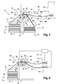
figure 1 représente une vue schématique en élévation d'une installation d'alimentation en gomme selon un mode de réalisation de l'invention ; - la
figure 2 représente une vue schématique en élévation d'une installation d'alimentation en gomme selon un mode de réalisation non revendiqué de l'installation.
- the
figure 1 is a schematic elevational view of a rubber supply installation according to one embodiment of the invention; - the
figure 2 is a diagrammatic elevational view of a rubber supply facility according to an unclaimed embodiment of the plant.
On a représenté sur la
L'installation 10 comprend un dispositif 12 fournisseur de gomme et un dispositif 14 consommateur de cette gomme.The
Dans ce qui suit, on distinguera les moyens amont et aval de l'installation 10 en se référant au sens de déplacement de la gomme, du dispositif fournisseur 12 vers le dispositif consommateur 14.In what follows, we distinguish the upstream and downstream means of the
Dans ce mode de réalisation de l'invention, le dispositif 12 fournisseur de gomme comprend des moyens amont 16 de stockage de gomme, par exemple une palette dans laquelle est stockée une bande de gomme M.In this embodiment of the invention, the
La bande de gomme M est destinée à être déplacée depuis le dispositif fournisseur 12 vers le dispositif consommateur 14 à l'aide de moyens qui seront décrits ultérieurement.The rubber band M is intended to be moved from the
Dans l'exemple décrit, la bande de gomme M a une largeur d'environ 200 mm et une épaisseur moyenne d'environ 10 mm. En variante, les largeur et épaisseur de la bande de gomme pourraient être différentes. En particulier, la largeur de la bande de gomme pourrait être supérieure à 200 mm et atteindre 800 mm. La bande de gomme M est pliée longitudinalement en boustrophédon dans les moyens amont de stockage 16.In the example described, the rubber band M has a width of about 200 mm and an average thickness of about 10 mm. Alternatively, the width and thickness of the rubber band could be different. In particular, the width of the rubber band could be greater than 200 mm and reach 800 mm. The rubber band M is folded longitudinally into boustrophedon in the upstream storage means 16.
Les moyens amont de stockage 16 sont portés par une embase 18 formant un premier support monté mobile en rotation autour d'un axe géométrique Z sensiblement vertical.The upstream storage means 16 are carried by a base 18 forming a first support rotatably mounted about a substantially vertical geometric axis Z.
Afin de déplacer la bande de gomme vers le dispositif consommateur 14, l'installation 10 comprend des moyens de déplacement 20 portés par un support 22. Le support 22 est porté par un mât 23 vertical dont l'axe coïncide sensiblement avec l'axe Z. Plus particulièrement, les moyens de déplacement 20 comprennent deux rouleaux d'entraînement 24 superposés, montés rotatifs autour d'axes respectifs parallèles, sur le support 22. La bande de gomme M est entraînée par passage entre ces rouleaux 24.In order to move the rubber band towards the
Le support 22 porte également des moyens 26 de guidage de la bande de gomme M à travers le support 22.The
Les moyens de guidage 26 comprennent, par exemple, un organe de guidage amont, formant passant 28, deux rouleaux de guidage 29 montés rotatifs sur le support 22 respectivement en amont et en aval des rouleaux d'entraînement 24, et deux organes de guidage aval, formés par des plateaux 30, 32.The guiding means 26 comprise, for example, an upstream guide member, forming a
Le dispositif consommateur 14, formé par l'extrudeuse, comprend une vis sans fin d'extrusion V. Dans l'exemple décrit, le diamètre de la vis sans fin V est inférieur à 90 mm si bien que l'extrudeuse a une capacité de consommation de gomme relativement limitée, le débit de gomme extrudée restant inférieur à 3 kg/minute. L'extrudeuse consomme le reste de la bande de gomme, désigné par la référence MC.The
Pour adapter la largeur de la bande de gomme M à la capacité relativement faible de consommation du dispositif 14, l'installation 10 comprend des moyens 34 de prélèvement continu d'une partie, appelée reliquat R, de la bande de gomme M. Ces moyens de prélèvement 34 sont agencés en amont du dispositif consommateur 14.To adapt the width of the rubber band M to the relatively low consumption capacity of the
Ainsi, dans l'exemple illustré, les moyens de prélèvement 34 comprennent des moyens 36 de découpage en continu d'une bande prélevée de la bande de gomme M. Ces moyens de découpage 36, portés par les rouleaux d'entraînement 24, comprennent au moins une lame rotative, portée par un des rouleaux d'entraînement 24, voire deux lames rotatives, portées par les deux rouleaux d'entraînement 24, formant ciseaux.Thus, in the example shown, the sampling means 34 comprise means 36 for continuously cutting a strip taken from the rubber band M. These cutting means 36, carried by the
De façon que la position transversale de la bande de gomme M par rapport à la direction longitudinale de découpage de la bande de reliquat R reste sensiblement constante, l'installation 10 comprend des moyens 38 de positionnement automatique transversal des moyens de découpage 34 par rapport à des bords longitudinaux de la bande de gomme M.So that the transverse position of the rubber band M with respect to the longitudinal direction of cutting of the residual strip R remains substantially constant, the
Ainsi, dans l'exemple illustré, les moyens de positionnement transversal 38 sont agencés entre le support 22 et l'extrémité supérieure du mât 23.Thus, in the example shown, the transverse positioning means 38 are arranged between the
Dans ce mode de réalisation de l'invention, l'installation 10 comprend des moyens aval 40 de stockage du reliquat R. Ces moyens aval 40 comprennent, par exemple, une palette 42 portée par l'embase 18. Cette embase 18 forme ainsi des moyens 43 de permutation des moyens de stockage amont 12 et aval 40.In this embodiment of the invention, the
De préférence, l'installation 10 comprend également des moyens 44 de régulation du débit d'alimentation du dispositif consommateur 14 par régulation de la largeur de la bande de gomme formant le reliquat R.Preferably, the
Entre le dispositif consommateur 14 et l'installation d'alimentation 10, il est possible de former dans la bande MC une boucle de compensation 46 de longueur variable. La variation de longueur de la boucle 46 peut-être détectée à l'aide de moyens 48 de détection continue de cette variation, par exemple un palpeur oscillant 50 dont l'angle d'oscillation θ évolue avec la variation de longueur de la boucle, ou en variante à l'aide de moyens 48A, 48B de détection d'extrema de la longueur de la boucle. Sur la
D'autres types de moyens 48 de détection de la variation de longueur peuvent être utilisés, avec ou sans contact avec la boucle.Other types of length variation detection means 48 may be used, with or without contact with the loop.
L'installation 10 permet de mettre en oeuvre un procédé d'alimentation en gomme du dispositif consommateur 14 dont on précisera ci-dessous les principaux aspects liés à l'invention.The
Pour alimenter en gomme le dispositif consommateur 14, on déplace en continu la bande de gomme M depuis le dispositif fournisseur 12 vers le dispositif consommateur 14 à l'aide des moyens de déplacement 20.To supply rubber to the
Au cours de ce déplacement continu, et avant d'atteindre le dispositif consommateur 14, on prélève en continu le reliquat R à l'aide des moyens 34.During this continuous movement, and before reaching the
Dans l'exemple décrit, le reliquat R est prélevé par découpage en continu de la bande formant la bande de gomme M. De préférence, la bande de reliquat a une largeur comprise entre la moitié et neuf dixièmes de la bande de gomme.In the example described, the residue R is taken by continuous cutting of the band forming the rubber band M. Preferably, the leftover strip has a width of between one half and nine tenths of the rubber band.
Au fur et à mesure du prélèvement du reliquat R, ce dernier est stocké dans les moyens 40. Après épuisement de la bande de gomme M dans les moyens amont 12 de stockage, on permute ces moyens amont 12 avec les moyens de stockage aval 40 qui tiennent lieu par la suite de moyens de stockage amont. Le reliquat R est, comme la bande de gomme M initiale, déplacé en continu depuis le dispositif fournisseur 12 vers le dispositif consommateur 14, un nouveau reliquat étant prélevé lors de ce déplacement de façon analogue à ce qui a été décrit précédemment.As and when the balance R is collected, the latter is stored in the
On règle la vitesse de défilement en fonction des variations de la longueur de la boucle. Les moyens 48 de détection continue permettent une régulation en continu de cette vitesse. Les moyens 48A, 48B de détection d'extrema de la longueur de la boucle permettent une régulation par mise en marche ou arrêt des moyens de déplacement 20.The scrolling speed is adjusted according to the variations of the length of the loop. The means 48 for continuous detection allow continuous regulation of this speed. The means 48A, 48B for detecting the extrema of the length of the loop allow regulation by starting or stopping the moving
Sur la
Dans ce cas, l'installation 10 comprend deux dispositifs consommateurs de gomme, à savoir le premier dispositif 14 tel que décrit précédemment et un second dispositif 14A, formé par exemple comme le premier dispositif 14, par une extrudeuse.In this case, the
On alimente le second dispositif consommateur 14A avec le reliquat R. Le cas échéant, on régule les débits d'alimentation des deux dispositifs consommateurs 14, 14A de façon à ce qu'ils soient identiques, en régulant la largeur du reliquat R à l'aide des moyens 44. Dans le cas où les premier 14 et second 14A dispositifs consommateurs sont formés par deux extrudeuses dont les débits en gomme extrudée sont différents, on peut également réguler les débits d'alimentation à l'aide des moyens 44.The
Claims (11)
Applications Claiming Priority (1)
| Application Number | Priority Date | Filing Date | Title |
|---|---|---|---|
| FR0752514A FR2910835B1 (en) | 2007-01-03 | 2007-01-03 | METHOD FOR FEEDING A GUM CONSUMER DEVICE AND PUMP SUPPLYING APPARATUS THEREOF |
Publications (2)
| Publication Number | Publication Date |
|---|---|
| EP1941985A1 true EP1941985A1 (en) | 2008-07-09 |
| EP1941985B1 EP1941985B1 (en) | 2009-07-08 |
Family
ID=38222578
Family Applications (1)
| Application Number | Title | Priority Date | Filing Date |
|---|---|---|---|
| EP20070123948 Not-in-force EP1941985B1 (en) | 2007-01-03 | 2007-12-21 | Method of supplying rubber to a rubber-consuming device and facility for supplying rubber to this rubber-consuming device |
Country Status (8)
| Country | Link |
|---|---|
| US (1) | US7708547B2 (en) |
| EP (1) | EP1941985B1 (en) |
| JP (1) | JP5196999B2 (en) |
| CN (1) | CN101224610B (en) |
| AT (1) | ATE435733T1 (en) |
| BR (1) | BRPI0800024B1 (en) |
| DE (1) | DE602007001517D1 (en) |
| FR (1) | FR2910835B1 (en) |
Cited By (1)
| Publication number | Priority date | Publication date | Assignee | Title |
|---|---|---|---|---|
| FR2957292A1 (en) * | 2010-03-15 | 2011-09-16 | Michelin Soc Tech | Continuous web for supplying transformation machine, has section adapted such that compactness of web is higher than or equal to thickness of thermoplastic film and defined as ratio between section of web and its perimeter |
Families Citing this family (4)
| Publication number | Priority date | Publication date | Assignee | Title |
|---|---|---|---|---|
| CN104647691A (en) * | 2014-12-24 | 2015-05-27 | 余姚华泰橡塑机械有限公司 | Driving feeding device of rubber injection molding machine |
| CN107351314B (en) * | 2016-05-09 | 2020-04-07 | 钜钢机械股份有限公司 | Method and apparatus for supplying rubber material to injection molding machine |
| JP6503123B1 (en) * | 2018-09-07 | 2019-04-17 | 中田エンヂニアリング株式会社 | Rubber material supply method and rubber material supply apparatus |
| CN112544495A (en) * | 2020-11-27 | 2021-03-26 | 郑州师范学院 | Birds inhabitation frame in lake wetland water area |
Citations (5)
| Publication number | Priority date | Publication date | Assignee | Title |
|---|---|---|---|---|
| GB615526A (en) * | 1940-05-11 | 1949-01-07 | Comp Generale Electricite | Improvements in or relating to extruding machines |
| US3396429A (en) * | 1966-08-01 | 1968-08-13 | Uniroyal Inc | Self-feed ram for extrusion equipment |
| US3738580A (en) * | 1972-02-24 | 1973-06-12 | Uniroyal Inc | Methods of processing uncured rubber and like raw materials, and article therefor |
| US3800894A (en) * | 1972-09-08 | 1974-04-02 | Werner & Pfleiderer | Device for gravimetrically uniformly feeding of components to a mixing device |
| JP2005022333A (en) * | 2003-07-04 | 2005-01-27 | Yokohama Rubber Co Ltd:The | Method and apparatus for feeding rubber-like elastomer |
Family Cites Families (4)
| Publication number | Priority date | Publication date | Assignee | Title |
|---|---|---|---|---|
| JPS5215634B2 (en) * | 1971-10-06 | 1977-05-02 | ||
| US5030079A (en) * | 1989-10-27 | 1991-07-09 | The Goodyear Tire & Rubber Company | Roller die extrusion and calendering apparatus |
| KR100497097B1 (en) * | 2003-04-24 | 2005-06-23 | 한국타이어 주식회사 | Extruding rubber control apparatus of radial tire |
| KR100651214B1 (en) * | 2005-11-18 | 2006-11-29 | 한국타이어 주식회사 | Extruding rubber storage and supply apparatus for tire |
-
2007
- 2007-01-03 FR FR0752514A patent/FR2910835B1/en not_active Expired - Fee Related
- 2007-12-21 AT AT07123948T patent/ATE435733T1/en not_active IP Right Cessation
- 2007-12-21 EP EP20070123948 patent/EP1941985B1/en not_active Not-in-force
- 2007-12-21 DE DE200760001517 patent/DE602007001517D1/en active Active
- 2007-12-28 JP JP2007342028A patent/JP5196999B2/en not_active Expired - Fee Related
-
2008
- 2008-01-03 BR BRPI0800024-7A patent/BRPI0800024B1/en not_active IP Right Cessation
- 2008-01-03 US US12/006,519 patent/US7708547B2/en active Active
- 2008-01-03 CN CN2008100020207A patent/CN101224610B/en not_active Expired - Fee Related
Patent Citations (5)
| Publication number | Priority date | Publication date | Assignee | Title |
|---|---|---|---|---|
| GB615526A (en) * | 1940-05-11 | 1949-01-07 | Comp Generale Electricite | Improvements in or relating to extruding machines |
| US3396429A (en) * | 1966-08-01 | 1968-08-13 | Uniroyal Inc | Self-feed ram for extrusion equipment |
| US3738580A (en) * | 1972-02-24 | 1973-06-12 | Uniroyal Inc | Methods of processing uncured rubber and like raw materials, and article therefor |
| US3800894A (en) * | 1972-09-08 | 1974-04-02 | Werner & Pfleiderer | Device for gravimetrically uniformly feeding of components to a mixing device |
| JP2005022333A (en) * | 2003-07-04 | 2005-01-27 | Yokohama Rubber Co Ltd:The | Method and apparatus for feeding rubber-like elastomer |
Cited By (1)
| Publication number | Priority date | Publication date | Assignee | Title |
|---|---|---|---|---|
| FR2957292A1 (en) * | 2010-03-15 | 2011-09-16 | Michelin Soc Tech | Continuous web for supplying transformation machine, has section adapted such that compactness of web is higher than or equal to thickness of thermoplastic film and defined as ratio between section of web and its perimeter |
Also Published As
| Publication number | Publication date |
|---|---|
| US7708547B2 (en) | 2010-05-04 |
| DE602007001517D1 (en) | 2009-08-20 |
| US20080197527A1 (en) | 2008-08-21 |
| FR2910835A1 (en) | 2008-07-04 |
| CN101224610A (en) | 2008-07-23 |
| JP2008183900A (en) | 2008-08-14 |
| JP5196999B2 (en) | 2013-05-15 |
| ATE435733T1 (en) | 2009-07-15 |
| EP1941985B1 (en) | 2009-07-08 |
| BRPI0800024A (en) | 2008-08-19 |
| CN101224610B (en) | 2013-08-28 |
| BRPI0800024B1 (en) | 2018-06-19 |
| FR2910835B1 (en) | 2010-08-13 |
Similar Documents
| Publication | Publication Date | Title |
|---|---|---|
| EP1941985B1 (en) | Method of supplying rubber to a rubber-consuming device and facility for supplying rubber to this rubber-consuming device | |
| EP0767036B1 (en) | Wire saw having a wire management system allowing for wire rollers of very large length | |
| EP0281511B1 (en) | Thread-cutting apparatus | |
| EP0101366B1 (en) | Cutting machine for pieces of web material | |
| EP3049223B1 (en) | Cutting process and cutting device by wire of a material | |
| EP1147864A2 (en) | High speed cutting device for cutting reinforcing elements for tyres | |
| EP3565777B1 (en) | Method and facility for continuously crosswinding gum strips about spools | |
| EP3429790B1 (en) | Method and device for cutting a plate or a panel of porous construction material | |
| EP1946888B1 (en) | Device for storing and dispensing continuous work belts for a robotic installation | |
| FR2648736A1 (en) | ELECTRIC DISCHARGE MACHINING MACHINE WITH ELECTRODE WIRE GUIDE ROLLER | |
| EP1036026B1 (en) | Machine for winding continuous sheet product for forming coils | |
| EP0328610B1 (en) | Process for cropping bars of hard materials and equipment for carrying out the process | |
| FR2954202A1 (en) | Process for polishing of test-tube by polishing machine with abrasive band, involves renewing part of abrasive band in contact with test-tube by part of another abrasive band so as to carry out homogeneous polishing of test-tube | |
| EP2268445A1 (en) | Position-measuring method and device adapted for the positioning of a wheel | |
| EP0263763B1 (en) | Apparatus for automatically preparing the ends of tubes made of reinforced rubber | |
| FR2604386A1 (en) | METHOD FOR AUTOMATICALLY ADVANCING A TROLLEY FROM A CUTTER TO A KNIFE, AND DEVICE FOR IMPLEMENTING SAID METHOD | |
| CN218657104U (en) | Multi-cutter-head loop line double-wheel cutting machine | |
| EP3197653B1 (en) | Cutting wire device comprising a wire detection and a wire bow measurement system and method of using the same | |
| FR3102087A1 (en) | Winding and Unwinding of a Strip of Gum and an Interlayer Carrying the Strip of Gum | |
| FR3102088A1 (en) | Winding and Unwinding of a Strip of Gum and an Interlayer Carrying the Strip of Gum | |
| FR2937576A1 (en) | Wooden revolution part i.e. fishing float, fabricating method, involves continuously adjusting distance between axes of cutting tools and axis of bar according to translation position of bar with respect to chassis | |
| EP1972562B1 (en) | Method of fixing a plastic handle to a metal package | |
| FR2571024A1 (en) | Bottle labelling machine | |
| WO2018055273A1 (en) | Process for cutting slices from an ingot made of hard material and abrasive wire | |
| FR2758755A1 (en) | Wood cutting machine tool |
Legal Events
| Date | Code | Title | Description |
|---|---|---|---|
| PUAI | Public reference made under article 153(3) epc to a published international application that has entered the european phase |
Free format text: ORIGINAL CODE: 0009012 |
|
| AK | Designated contracting states |
Kind code of ref document: A1 Designated state(s): AT BE BG CH CY CZ DE DK EE ES FI FR GB GR HU IE IS IT LI LT LU LV MC MT NL PL PT RO SE SI SK TR |
|
| AX | Request for extension of the european patent |
Extension state: AL BA HR MK RS |
|
| 17P | Request for examination filed |
Effective date: 20080609 |
|
| 17Q | First examination report despatched |
Effective date: 20080820 |
|
| GRAP | Despatch of communication of intention to grant a patent |
Free format text: ORIGINAL CODE: EPIDOSNIGR1 |
|
| AKX | Designation fees paid |
Designated state(s): AT BE BG CH CY CZ DE DK EE ES FI FR GB GR HU IE IS IT LI LT LU LV MC MT NL PL PT RO SE SI SK TR |
|
| GRAS | Grant fee paid |
Free format text: ORIGINAL CODE: EPIDOSNIGR3 |
|
| GRAA | (expected) grant |
Free format text: ORIGINAL CODE: 0009210 |
|
| AK | Designated contracting states |
Kind code of ref document: B1 Designated state(s): AT BE BG CH CY CZ DE DK EE ES FI FR GB GR HU IE IS IT LI LT LU LV MC MT NL PL PT RO SE SI SK TR |
|
| REG | Reference to a national code |
Ref country code: GB Ref legal event code: FG4D Free format text: NOT ENGLISH |
|
| REG | Reference to a national code |
Ref country code: CH Ref legal event code: EP |
|
| REG | Reference to a national code |
Ref country code: IE Ref legal event code: FG4D |
|
| REF | Corresponds to: |
Ref document number: 602007001517 Country of ref document: DE Date of ref document: 20090820 Kind code of ref document: P |
|
| PG25 | Lapsed in a contracting state [announced via postgrant information from national office to epo] |
Ref country code: SI Free format text: LAPSE BECAUSE OF FAILURE TO SUBMIT A TRANSLATION OF THE DESCRIPTION OR TO PAY THE FEE WITHIN THE PRESCRIBED TIME-LIMIT Effective date: 20090708 |
|
| NLV1 | Nl: lapsed or annulled due to failure to fulfill the requirements of art. 29p and 29m of the patents act | ||
| PG25 | Lapsed in a contracting state [announced via postgrant information from national office to epo] |
Ref country code: IS Free format text: LAPSE BECAUSE OF FAILURE TO SUBMIT A TRANSLATION OF THE DESCRIPTION OR TO PAY THE FEE WITHIN THE PRESCRIBED TIME-LIMIT Effective date: 20091108 Ref country code: FI Free format text: LAPSE BECAUSE OF FAILURE TO SUBMIT A TRANSLATION OF THE DESCRIPTION OR TO PAY THE FEE WITHIN THE PRESCRIBED TIME-LIMIT Effective date: 20090708 Ref country code: ES Free format text: LAPSE BECAUSE OF FAILURE TO SUBMIT A TRANSLATION OF THE DESCRIPTION OR TO PAY THE FEE WITHIN THE PRESCRIBED TIME-LIMIT Effective date: 20091019 Ref country code: AT Free format text: LAPSE BECAUSE OF FAILURE TO SUBMIT A TRANSLATION OF THE DESCRIPTION OR TO PAY THE FEE WITHIN THE PRESCRIBED TIME-LIMIT Effective date: 20090708 Ref country code: LT Free format text: LAPSE BECAUSE OF FAILURE TO SUBMIT A TRANSLATION OF THE DESCRIPTION OR TO PAY THE FEE WITHIN THE PRESCRIBED TIME-LIMIT Effective date: 20090708 |
|
| REG | Reference to a national code |
Ref country code: IE Ref legal event code: FD4D |
|
| PG25 | Lapsed in a contracting state [announced via postgrant information from national office to epo] |
Ref country code: PL Free format text: LAPSE BECAUSE OF FAILURE TO SUBMIT A TRANSLATION OF THE DESCRIPTION OR TO PAY THE FEE WITHIN THE PRESCRIBED TIME-LIMIT Effective date: 20090708 Ref country code: LV Free format text: LAPSE BECAUSE OF FAILURE TO SUBMIT A TRANSLATION OF THE DESCRIPTION OR TO PAY THE FEE WITHIN THE PRESCRIBED TIME-LIMIT Effective date: 20090708 Ref country code: NL Free format text: LAPSE BECAUSE OF FAILURE TO SUBMIT A TRANSLATION OF THE DESCRIPTION OR TO PAY THE FEE WITHIN THE PRESCRIBED TIME-LIMIT Effective date: 20090708 |
|
| PG25 | Lapsed in a contracting state [announced via postgrant information from national office to epo] |
Ref country code: PT Free format text: LAPSE BECAUSE OF FAILURE TO SUBMIT A TRANSLATION OF THE DESCRIPTION OR TO PAY THE FEE WITHIN THE PRESCRIBED TIME-LIMIT Effective date: 20091109 Ref country code: BG Free format text: LAPSE BECAUSE OF FAILURE TO SUBMIT A TRANSLATION OF THE DESCRIPTION OR TO PAY THE FEE WITHIN THE PRESCRIBED TIME-LIMIT Effective date: 20091008 |
|
| PG25 | Lapsed in a contracting state [announced via postgrant information from national office to epo] |
Ref country code: RO Free format text: LAPSE BECAUSE OF FAILURE TO SUBMIT A TRANSLATION OF THE DESCRIPTION OR TO PAY THE FEE WITHIN THE PRESCRIBED TIME-LIMIT Effective date: 20090708 Ref country code: CZ Free format text: LAPSE BECAUSE OF FAILURE TO SUBMIT A TRANSLATION OF THE DESCRIPTION OR TO PAY THE FEE WITHIN THE PRESCRIBED TIME-LIMIT Effective date: 20090708 Ref country code: DK Free format text: LAPSE BECAUSE OF FAILURE TO SUBMIT A TRANSLATION OF THE DESCRIPTION OR TO PAY THE FEE WITHIN THE PRESCRIBED TIME-LIMIT Effective date: 20090708 Ref country code: IE Free format text: LAPSE BECAUSE OF FAILURE TO SUBMIT A TRANSLATION OF THE DESCRIPTION OR TO PAY THE FEE WITHIN THE PRESCRIBED TIME-LIMIT Effective date: 20090708 Ref country code: EE Free format text: LAPSE BECAUSE OF FAILURE TO SUBMIT A TRANSLATION OF THE DESCRIPTION OR TO PAY THE FEE WITHIN THE PRESCRIBED TIME-LIMIT Effective date: 20090708 |
|
| PLBE | No opposition filed within time limit |
Free format text: ORIGINAL CODE: 0009261 |
|
| STAA | Information on the status of an ep patent application or granted ep patent |
Free format text: STATUS: NO OPPOSITION FILED WITHIN TIME LIMIT |
|
| PG25 | Lapsed in a contracting state [announced via postgrant information from national office to epo] |
Ref country code: SK Free format text: LAPSE BECAUSE OF FAILURE TO SUBMIT A TRANSLATION OF THE DESCRIPTION OR TO PAY THE FEE WITHIN THE PRESCRIBED TIME-LIMIT Effective date: 20090708 |
|
| 26N | No opposition filed |
Effective date: 20100409 |
|
| BERE | Be: lapsed |
Owner name: MICHELIN RECHERCHE ET TECHNIQUE S.A. Effective date: 20091231 Owner name: SOC. DE TECHNOLOGIE MICHELIN Effective date: 20091231 |
|
| PG25 | Lapsed in a contracting state [announced via postgrant information from national office to epo] |
Ref country code: MC Free format text: LAPSE BECAUSE OF NON-PAYMENT OF DUE FEES Effective date: 20100701 |
|
| PG25 | Lapsed in a contracting state [announced via postgrant information from national office to epo] |
Ref country code: GR Free format text: LAPSE BECAUSE OF FAILURE TO SUBMIT A TRANSLATION OF THE DESCRIPTION OR TO PAY THE FEE WITHIN THE PRESCRIBED TIME-LIMIT Effective date: 20091009 Ref country code: BE Free format text: LAPSE BECAUSE OF NON-PAYMENT OF DUE FEES Effective date: 20091231 |
|
| PG25 | Lapsed in a contracting state [announced via postgrant information from national office to epo] |
Ref country code: MT Free format text: LAPSE BECAUSE OF FAILURE TO SUBMIT A TRANSLATION OF THE DESCRIPTION OR TO PAY THE FEE WITHIN THE PRESCRIBED TIME-LIMIT Effective date: 20090708 Ref country code: LU Free format text: LAPSE BECAUSE OF NON-PAYMENT OF DUE FEES Effective date: 20091221 |
|
| PG25 | Lapsed in a contracting state [announced via postgrant information from national office to epo] |
Ref country code: HU Free format text: LAPSE BECAUSE OF FAILURE TO SUBMIT A TRANSLATION OF THE DESCRIPTION OR TO PAY THE FEE WITHIN THE PRESCRIBED TIME-LIMIT Effective date: 20100109 |
|
| PG25 | Lapsed in a contracting state [announced via postgrant information from national office to epo] |
Ref country code: TR Free format text: LAPSE BECAUSE OF FAILURE TO SUBMIT A TRANSLATION OF THE DESCRIPTION OR TO PAY THE FEE WITHIN THE PRESCRIBED TIME-LIMIT Effective date: 20090708 |
|
| PG25 | Lapsed in a contracting state [announced via postgrant information from national office to epo] |
Ref country code: CY Free format text: LAPSE BECAUSE OF FAILURE TO SUBMIT A TRANSLATION OF THE DESCRIPTION OR TO PAY THE FEE WITHIN THE PRESCRIBED TIME-LIMIT Effective date: 20090708 |
|
| PG25 | Lapsed in a contracting state [announced via postgrant information from national office to epo] |
Ref country code: IT Free format text: LAPSE BECAUSE OF NON-PAYMENT OF DUE FEES Effective date: 20101221 |
|
| REG | Reference to a national code |
Ref country code: CH Ref legal event code: PL |
|
| GBPC | Gb: european patent ceased through non-payment of renewal fee |
Effective date: 20111221 |
|
| PG25 | Lapsed in a contracting state [announced via postgrant information from national office to epo] |
Ref country code: SE Free format text: LAPSE BECAUSE OF FAILURE TO SUBMIT A TRANSLATION OF THE DESCRIPTION OR TO PAY THE FEE WITHIN THE PRESCRIBED TIME-LIMIT Effective date: 20090708 |
|
| PG25 | Lapsed in a contracting state [announced via postgrant information from national office to epo] |
Ref country code: CH Free format text: LAPSE BECAUSE OF NON-PAYMENT OF DUE FEES Effective date: 20111231 Ref country code: GB Free format text: LAPSE BECAUSE OF NON-PAYMENT OF DUE FEES Effective date: 20111221 Ref country code: LI Free format text: LAPSE BECAUSE OF NON-PAYMENT OF DUE FEES Effective date: 20111231 |
|
| REG | Reference to a national code |
Ref country code: FR Ref legal event code: PLFP Year of fee payment: 9 |
|
| REG | Reference to a national code |
Ref country code: FR Ref legal event code: PLFP Year of fee payment: 10 |
|
| REG | Reference to a national code |
Ref country code: FR Ref legal event code: PLFP Year of fee payment: 11 |
|
| REG | Reference to a national code |
Ref country code: DE Ref legal event code: R079 Ref document number: 602007001517 Country of ref document: DE Free format text: PREVIOUS MAIN CLASS: B29C0047100000 Ipc: B29C0048285000 |
|
| PGFP | Annual fee paid to national office [announced via postgrant information from national office to epo] |
Ref country code: DE Payment date: 20211210 Year of fee payment: 15 Ref country code: FR Payment date: 20211224 Year of fee payment: 15 |
|
| PGFP | Annual fee paid to national office [announced via postgrant information from national office to epo] |
Ref country code: IT Payment date: 20211224 Year of fee payment: 15 |
|
| REG | Reference to a national code |
Ref country code: DE Ref legal event code: R119 Ref document number: 602007001517 Country of ref document: DE |
|
| PG25 | Lapsed in a contracting state [announced via postgrant information from national office to epo] |
Ref country code: DE Free format text: LAPSE BECAUSE OF NON-PAYMENT OF DUE FEES Effective date: 20230701 |
|
| PG25 | Lapsed in a contracting state [announced via postgrant information from national office to epo] |
Ref country code: FR Free format text: LAPSE BECAUSE OF NON-PAYMENT OF DUE FEES Effective date: 20221231 |
|
| PG25 | Lapsed in a contracting state [announced via postgrant information from national office to epo] |
Ref country code: IT Free format text: LAPSE BECAUSE OF NON-PAYMENT OF DUE FEES Effective date: 20221221 |