EP1940565B1 - Hazardous waste transfer port system and storage container - Google Patents
Hazardous waste transfer port system and storage container Download PDFInfo
- Publication number
- EP1940565B1 EP1940565B1 EP06844193.0A EP06844193A EP1940565B1 EP 1940565 B1 EP1940565 B1 EP 1940565B1 EP 06844193 A EP06844193 A EP 06844193A EP 1940565 B1 EP1940565 B1 EP 1940565B1
- Authority
- EP
- European Patent Office
- Prior art keywords
- storage vessel
- port
- vessel
- ring
- cover
- Prior art date
- Legal status (The legal status is an assumption and is not a legal conclusion. Google has not performed a legal analysis and makes no representation as to the accuracy of the status listed.)
- Active
Links
- 239000002920 hazardous waste Substances 0.000 title description 3
- 238000003032 molecular docking Methods 0.000 claims description 40
- 239000002699 waste material Substances 0.000 claims description 19
- 239000000463 material Substances 0.000 claims description 11
- 238000007789 sealing Methods 0.000 claims description 3
- 210000005069 ears Anatomy 0.000 description 17
- 238000000034 method Methods 0.000 description 7
- 238000011109 contamination Methods 0.000 description 3
- 238000013459 approach Methods 0.000 description 2
- 239000013056 hazardous product Substances 0.000 description 2
- 238000009434 installation Methods 0.000 description 2
- 230000002285 radioactive effect Effects 0.000 description 2
- 230000000903 blocking effect Effects 0.000 description 1
- -1 for example Substances 0.000 description 1
- 231100001261 hazardous Toxicity 0.000 description 1
- 239000000383 hazardous chemical Substances 0.000 description 1
- 230000001681 protective effect Effects 0.000 description 1
- 239000012857 radioactive material Substances 0.000 description 1
- 231100000331 toxic Toxicity 0.000 description 1
- 230000002588 toxic effect Effects 0.000 description 1
Images


Classifications
-
- B—PERFORMING OPERATIONS; TRANSPORTING
- B65—CONVEYING; PACKING; STORING; HANDLING THIN OR FILAMENTARY MATERIAL
- B65G—TRANSPORT OR STORAGE DEVICES, e.g. CONVEYORS FOR LOADING OR TIPPING, SHOP CONVEYOR SYSTEMS OR PNEUMATIC TUBE CONVEYORS
- B65G69/00—Auxiliary measures taken, or devices used, in connection with loading or unloading
- B65G69/18—Preventing escape of dust
- B65G69/181—Preventing escape of dust by means of sealed systems
- B65G69/183—Preventing escape of dust by means of sealed systems with co-operating closure members on each of the parts of a separable transfer channel
Definitions
- the invention pertains to a system for the secure transfer of material and in particular of hazardous material from an isolated environment to a storage container external to that environment.
- material can be a hazardous radioactive or toxic material that needs to be transferred from a containment enclosure such as a closed storage basin or room to a portable storage vessel.
- a containment cell will typically have a wall or floor with a transfer port for removal of the objectionable material to the portable vessel. It is important that the transfer equipment enable secure transfer of the material so as to avoid contamination of the surrounding environment. This gives rise to a requirement for a system for the secure transfer of the material from the contaimnent area to the storage vessel.
- US5263521 discloses a system for transferring hazardous waste into a storage vessel.
- the system comprises a waste transfer flange closed by a door.
- This door comprises a bayonet connector that interlocks with a bayonet system of the cover of the storage vessel's top flange. By rotation, door and cover engage and release from flanges, such that they may be removed there from.
- the invention consists in a hazardous material transfer system according to claim 1.
- Waste transfer system 20 is for the transfer of hazardous waste from a containment cell 22 into a waste storage container.
- the waste storage container can include a storage vessel 35 which can be a drum liner that fits in a standard 208-liter (55-gallon) drum.
- Containment cell 22 has a cell floor 24 that separates it from a waste collection room 25 which will generally have a cleaner environment.
- Containment cell 22 contains waste material, for example, radioactive material that should not be exposed to the outside environment.
- Floor 24 has a circular waste transfer port 28.
- a port door assembly 30 is installed on the containment side of cell floor 24.
- Port door assembly includes a port door 40 to close the port 28.
- a funnel assembly 31 is provided for installation in the port 28 when the port door is clear of the port.
- a docking station 33 is installed on the collection room side of floor 24 for docking the storage vessel 35 in sealed engagement with respect to the cell 22 during a waste material transfer procedure.
- the door assembly 30 includes the port door 40 movable into and out of closing and sealed engagement with the port 28.
- a flanged ring or cell flange 41 is installed in the port 28 and defines a passage between the containment cell 22 and the collection room 25.
- the door 40 closely fits the interior perimeter of the passage of cell flange 41.
- a pivot block 46 is attached to the top of door 40.
- a pivot pin 47 connects the pivot block 46 to a hinge bar 44.
- the opposite end of the hinge bar 44 is connected to a gear box 43 by a driven shaft 49.
- Gear box 43 extends through the floor 24.
- Gear box 43 contains a plurality of interconnected gears 50.
- a drive shaft 52 is installed in gear box 43 on the collection room side of the floor 24.
- An electric motor 53 drives the drive shaft 52. Operation of the electric motor 53 moves the door 40 between the open and closed positions.
- the funnel assembly 31 is moveable into and out of position with respect to the port 28.
- the funnel assembly includes a pivot block 56 mounted to the floor 24. Pivot arms 57 are pivotally connected to the pivot block 56.
- a protective funnel 59 is connected to the other end of the pivot arms 57.
- a handle 62 is connected to the funnel. The funnel 59 is moved into and out of engagement with the port 28 by manipulation of the handle 62. The handle 62 is remotely manipulated.
- the purpose of the funnel 59 is to cover the sealing components of the door assembly and protect them from impact and debris during waste transfer.
- Storage vessel 35 is housed in a standard 55-gallon drum 36 that is carried on a moveable trolley or bogie 38 with a scissors lift 39 for positioning beneath the port 28.
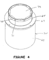
- Figure 4 shows the storage vessel 35 apart from the 55-gallon drum 36.
- the vessel 35 has a cylindrical body 64 and a narrower neck 65.
- the vessel 35 is closed by a cover 73 that engages and disengages from neck 65 by rotational movement such as with a bayonet connection or a screw connection.
- Body 64 has a diameter to fit closely within the drum 36.
- a centering guide collar 67 is located on neck 65 and carries an outwardly directed flexible centering disk. The purpose of the centering disk is to aid in centering the vessel 35 inside a 55-gallon drum.
- a collar 70 is attached to the end of the neck 65 (see Figure 6A ).
- Alignment lugs 71 radiate outward from the collar 70. The alignment lugs engage the docking station 33 as will be described.
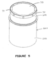
- Vessel 35 of Figure 4 installs in a standard unlined 208-liter (55-gallon) drum. Hazardous materials may require storage in a lined 208-liter (55 - gallon) drum.
- Figure 5 shows a storage vessel 35A for installation in a lined drum. The body portion 64A has a reduced diameter to accommodate the liner thickness of the lined 208 - liter (55-gallon) drum.
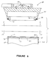
- Figure 6 shows the port door 40 aligned for docking to the cover 73 of closed storage vessel 35.
- Port door 40 has a truncated conical body 75 ending in a reduced diameter neck 76.
- the closure face of port door is shown in Figure 9 .
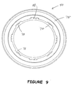
- a first connector set includes a perimeter of fastening ears 78 equally spaced about neck 76 and extending radially outward. Stop pins 83 extend inward from the ears 78 to the neck 76.
- Cover 73 has a flat base 80 that carries a second and outwardly facing connector set.
- a circumferential rim 81 extends perpendicular from the base (see Figures 6A and 10 ).
- a lip 82 is attached to the end of the rim 81. Lip 82 is parallel to and spaced from the base 80 defining an interior channel 77 and an exterior channel 74 ( Figure 8A ).
- the second connector set includes a perimeter of spaced apart notches 84 on lip 82 facing centrally inward to define a set of ears or tabs 85.
- the notches 84 are sized and spaced to correspond to the ears 78 on the closure face of the port door 40.
- the closure face of port door 40 and the interior face of vessel cover 73 interlock for mutual sealing.
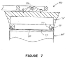
- the ears 78 pass between the outside notches 84 to a location in the channel 77. This relationship is shown in Figure 7 as well as Figure 8A .
- the ears 78 move out of alignment with the notches 84 and into intercepting alignment with the lip 82.
- the port door 40 is interlocked with the vessel cover 73.
- a seal 79 on port door 40 seals against the lip 82.
- Further rotation between the port door and the vessel cover is stopped by the stop pins 83. Such further rotation causes the vessel cover 73 to disengage from the vessel neck 65.
- Figure 8A shows a tab 85 of cover 73 located in the channel of door 40 defined by neck 76 and an ear 78. A portion of the tab 85 is shown broken away to show a stop pin 83.
- Figures 6 and 7 show the vessel cover 73 attached to vessel 35.
- Figure 8 shows the vessel cover attached to the port door and disengaged and moved away from the vessel 35.
- Figure 11 is a plan view of the inner face of the cover 73.
- Figure 12 is a view that shows the open end of the vessel 35.
- a seal 89 on collar 70 attached to vessel neck 65 seals the vessel cover 73 when attached to the vessel as shown in Figure 6 .
- cover 73 has a third connector set for connection to a fourth connector set on the open end of vessel 35.
- base 80 has a perimeter of notches 86 defining ears or tabs 87 which define the channel 74.
- vessel 35 has a fourth connector set that includes a perimeter of spaced apart ears 88 extending inward from neck 65. Ears 88 are spaced apart by notches 91 in correspondence to the spacing of the notches 86 on the inner face of the cover 73.
- Cover 73 is assembled to the vessel 35 with the ears 88 of vessel 35 passing between the notches 86. Vessel 35 is rotated relative to the cover so that the ears move into the channel 74 ( Figure 6A ). Stop members 90 limit the relative rotation between cover 73 and the open end of vessel 35.
- the first and second connector sets and the third and fourth connector sets are relatively arranged and spaced such that rotation of the vessel 35 in one direction will interlock the port door to the outside face of the cover 73 and disengage the cover 73 from the vessel 35.
- the vessel Upon engagement of the first and second connector sets the vessel is rotated to the position where the port door ears 78 are restrained in channel 77.
- a stop member 83 in the channel is positioned to stop further relative rotation of the port door and the vessel cover. Further rotation of the vessel results in the vessel cover rotation relative to the vessel to a position of release from the vessel.
- the release position can be determined by an additional stop member in the channel.
- the port door and vessel cover can be moved away from the vessel as shown in Figure 8 .
- a reverse procedure releases the port door from the vessel cover and engages the vessel cover with the vessel.
- the port door with the vessel cover attached in brought into engagement with the vessel.
- Ears 87 on the inner face of the cover 73 pass through the notches 91 between tabs 88.
- the tabs 88 are engaged in the channel 74.
- Rotation of the vessel 35 moves the tabs 88 and ears 87 into blocking relationship to connect the cover 73 to the vessel 35. Further relative rotation of the cover and the vessel is stopped by one or more stop members 90. Further rotation of the vessel 35 disengages the vessel cover from the port door by disengaging the first and second connector sets.
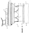
- Figure 13 shows the vessel 35 in approach to dock to the docking station 33.
- Figure 14 shows the vessel docked to the docking station 33.
- Figure 13 shows the alignment lugs 71 on the alignment collar 70 of vessel 35 positioned to be guided by docking ring ramp surfaces.
- Figure 14 shows the alignment lugs secured to docking station 33.
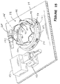
- FIG. 15 shows the docking station and a docking ring assembly 92 as viewed from underneath and apart from a storage vessel.
- the docking ring assembly 92 includes an inside docking ring 93 and a symmetrical outside docking ring 94.
- Each ring is a cylindrical segment with an inverted crown shape.
- the rings are concentric and assembled so that the outside ring 94 rotates relative to the inside ring 93.
- the rings have crown peaks separated by crown valleys or slots.
- Inside ring 93 has a circular array of crown peaks 96 spaced apart by vertical slots 97.
- the outside ring 94 has a corresponding symmetrical array of crown peaks 98 separated by vertical slots 99 that in the open position of the docking ring are aligned with the slots 97 of the inside ring.
- each crown peak 96 of the inside ring 93 has a horizontal locking slot 101 that intersects the vertical slot 97.
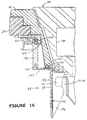
- the relationship between the inner and outer rings is shown in Figure 16 and in enlarged detail in Figure 17 .
- Port door 40 is shown closing the transfer port.
- the inner ring 93 has a horizontal rim 103 that is fastened to the lower surface of the cell flange 41 by suitable fasteners 104.
- the inner ring 93 is held stationary in surrounding relationship to the closure face of the port door 40.
- the outer ring 94 surrounds the inner ring 93 and slides concentrically relative to it.
- the outer ring 94 has an upper horizontal rim 107. Rim 107 is fastened to a connector ring 108 by fasteners 109.
- Connector ring 108 is connected to a drive ring 110 which rides on a fixed track 112 carried by a bearing assembly 114.
- Drive ring 110 is connected to a drive chain 115 by chain connectors 117 (see Figure 15 ).
- Chain 115 is trained through a gear box 120 ( Figure 15 ) connected to floor 24 and powered by docking drive motor 118. Operation of the chain 115 moves the drive ring 110 and causes the outer ring 94 to move relative to the inner ring 93.
- Motor 118 can drive chain 115 in clockwise or counterclockwise direction.
- Proximity sensors 121 are mounted about the circumference of the docking assembly 33 to sense the proximity of a vessel 35.
- a containment cell 22 holds contaminated material in need of disposition without contaminating the exterior environment. This may include for example instrumentation and products exposed to a radioactive environment.
- a storage vessel is prepared in combination with a 55-gallon storage drum 36. Other suitable containment and storage vessels could be used.
- the containment cell has a waste transfer port 28 defined in a floor 24.
- Floor 24 is located over a collection room 25.
- the port door 40 normally closes the transfer port 28 and is tightly seated therein to prevent contaminate leakage from the containment cell.
- the closure face of the port door faces the collection room.
- the drum 36 with the empty and closed vessel 35 is transported by a bogie 38 to a location beneath the transfer port 28.
- Drum lift 39 elevates the drum 36 and vessel 35 toward the docking station 33.
- the alignment lugs 71 are intercepted by the ramp surfaces between adjacent crown peaks on the docking ring assembly 92 as shown in Figure 13 .
- the drum 36 is permitted to rotate on the bogie 38.
- the lugs are guided to a docked position into slots 97, 99.
- the ears 78 on the closure face of the cover 40 have passed through notches 84 on the outer face of the vessel cover 73 in a pre-interlock position as shown in Figure 7 .
- the proximity sensors 121 have determined that the vessel is in position beneath the transfer port 28.
- the chain drive motor 118 is operated to drive the chain 115 to rotate the outer docking ring 94.
- the inner docking ring remains stationary and the alignment lugs 71 are moved into the horizontal slots 101 in the crown peaks 96 of the inner docking ring.
- This movement rotates the vessel 35 and the cover 73.
- the cover 73 rotates to a position where the ears 78 of port door 40 are in interlocked engagement with the rim 81 of cover 73.
- the same rotation is effective to disengage the cover from the vessel 35. In this position the ears 88 on the vessel are rotated to a position aligned with the notches 86 on the cover 73 whereby the cover can be moved away from the vessel 35.
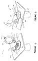
- the port door motor 53 is operated to move the port door away from the transfer port 28 to the port-door open position shown in Figure 3 .
- the outside face of the vessel cover 73 is tightly sealed against the closure face of the port door by the seal port door seal 79 so that neither is contaminated by the environment inside cell 22.
- the funnel 59 can be lowered into place in the transfer port 28.
- the funnel is manipulated through the use of remote manipulators (not shown) available in the containment cell to manipulate various items therein. The same manipulators are used to transfer material from the containment cell to the vessel.
- the funnel is removed and the port door is closed.
- the vessel cover is repositioned on the vessel while still interlocked with the port door.
- the chain drive motor is operated to move the chain 115 in a direction opposite to that of the opening procedure.
- the alignment lugs 71 are moved out of engagement with the horizontal slots 101 as the port door and the vessel cover disengage. The same rotational movement causes the vessel cover to interlock with the vessel 35. Once the cover is locked on the vessel the vessel is removed.
Description
- This application claims the benefit of United States Provisional Patent Application Serial Number
60/723,690 filed October 5, 2005 - The invention pertains to a system for the secure transfer of material and in particular of hazardous material from an isolated environment to a storage container external to that environment. Such material can be a hazardous radioactive or toxic material that needs to be transferred from a containment enclosure such as a closed storage basin or room to a portable storage vessel. A containment cell will typically have a wall or floor with a transfer port for removal of the objectionable material to the portable vessel. It is important that the transfer equipment enable secure transfer of the material so as to avoid contamination of the surrounding environment. This gives rise to a requirement for a system for the secure transfer of the material from the contaimnent area to the storage vessel.
-
US5263521 discloses a system for transferring hazardous waste into a storage vessel. The system comprises a waste transfer flange closed by a door. This door comprises a bayonet connector that interlocks with a bayonet system of the cover of the storage vessel's top flange. By rotation, door and cover engage and release from flanges, such that they may be removed there from. - The invention consists in a hazardous material transfer system according to
claim 1. -
-
Figure 1 is a side elevational view partly in section showing a waste transfer system installed relative to a collection room located beneath the floor of a containment cell, with the port door closed and a storage vessel poised to be moved into docking position; -
Figure 2 is a perspective view of a portion of the waste transfer system ofFigure 1 taken from an elevated vantage point; -
Figure 3 is a perspective view like that ofFigure 2 but showing the port door open preparatory to a waste transfer procedure; -
Figure 4 is a side view of an embodiment of a storage vessel that can be used in conjunction with a 208-liter (55-gallon) drum; -
Figure 5 is a side view of a another embodiment of a storage vessel that can be used in conjunction with a lined 208-liter (55-gallon) drum; -
Figure 6 is an enlarged sectional view of the port door in docking alignment with a storage vessel with the vessel cover attached to the storage vessel; -
Figure 6A is an enlarged view of a portion of the storage vessel and attached storage vessel cover ofFigure 6 ; -
Figure 7 is an enlarged sectional view of the port door engaged with the storage vessel cover with the cover attached to the storage vessel; -
Figure 8 is an enlarged sectional view of the port door locked to the storage vessel cover and moved away from the storage vessel; -
Figure 8A is an enlarged view of a portion of the port door and attached storage vessel cover ofFigure 8 ; -
Figure 9 is a view of the closure face of the port door ofFigure 6 taken along the line 9-9 thereof; -
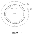
Figure 10 is a view of the outside face of the storage vessel cover shown inFigure 6 taken along the line 10-10 thereof; -
Figure 11 is a view of the inside face of the storage vessel cover shown inFigure 8 taken along the line 11-11 thereof; -
Figure 12 is a view of the open end of the storage vessel ofFigure 8 taken along the line 12-12 thereof; -
Figure 13 is a side view of a portion of the waste transfer system showing the storage vessel moved toward a docking position; -
Figure 14 is a side view like that ofFigure 13 showing the storage vessel docked; -
Figure 15 is an underside view of the docking station; -
Figure 16 is a sectional view showing the relationship between the cell flange, the port door and the docking station; and -
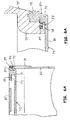
Figure 17 is an enlarged sectional view of a portion of the cell flange, port door and docking station shown inFigure 16 . - Referring to
Figures 1 through 3 , a waste transfer system is indicated generally at 20.Waste transfer system 20 is for the transfer of hazardous waste from acontainment cell 22 into a waste storage container. The waste storage container can include astorage vessel 35 which can be a drum liner that fits in a standard 208-liter (55-gallon) drum.Containment cell 22 has acell floor 24 that separates it from awaste collection room 25 which will generally have a cleaner environment.Containment cell 22 contains waste material, for example, radioactive material that should not be exposed to the outside environment. -
Floor 24 has a circularwaste transfer port 28. Aport door assembly 30 is installed on the containment side ofcell floor 24. Port door assembly includes aport door 40 to close theport 28. Afunnel assembly 31 is provided for installation in theport 28 when the port door is clear of the port. Adocking station 33 is installed on the collection room side offloor 24 for docking thestorage vessel 35 in sealed engagement with respect to thecell 22 during a waste material transfer procedure. - The
door assembly 30 includes theport door 40 movable into and out of closing and sealed engagement with theport 28. A flanged ring orcell flange 41 is installed in theport 28 and defines a passage between thecontainment cell 22 and thecollection room 25. Thedoor 40 closely fits the interior perimeter of the passage ofcell flange 41. - A
pivot block 46 is attached to the top ofdoor 40. Apivot pin 47 connects thepivot block 46 to ahinge bar 44. The opposite end of thehinge bar 44 is connected to agear box 43 by a drivenshaft 49. -
Gear box 43 extends through thefloor 24.Gear box 43 contains a plurality ofinterconnected gears 50. Adrive shaft 52 is installed ingear box 43 on the collection room side of thefloor 24. Anelectric motor 53 drives thedrive shaft 52. Operation of theelectric motor 53 moves thedoor 40 between the open and closed positions. - The
funnel assembly 31 is moveable into and out of position with respect to theport 28. When thedoor 40 is in the open and clear position ofFigure 3 , the funnel assembly is installed in the port. The funnel assembly includes apivot block 56 mounted to thefloor 24.Pivot arms 57 are pivotally connected to thepivot block 56. Aprotective funnel 59 is connected to the other end of thepivot arms 57. Ahandle 62 is connected to the funnel. Thefunnel 59 is moved into and out of engagement with theport 28 by manipulation of thehandle 62. Thehandle 62 is remotely manipulated. The purpose of thefunnel 59 is to cover the sealing components of the door assembly and protect them from impact and debris during waste transfer. -
Storage vessel 35 is housed in a standard 55-gallon drum 36 that is carried on a moveable trolley orbogie 38 with ascissors lift 39 for positioning beneath theport 28.Figure 4 shows thestorage vessel 35 apart from the 55-gallon drum 36. Thevessel 35 has acylindrical body 64 and anarrower neck 65. Thevessel 35 is closed by acover 73 that engages and disengages fromneck 65 by rotational movement such as with a bayonet connection or a screw connection.Body 64 has a diameter to fit closely within thedrum 36. A centeringguide collar 67 is located onneck 65 and carries an outwardly directed flexible centering disk. The purpose of the centering disk is to aid in centering thevessel 35 inside a 55-gallon drum. - A
collar 70 is attached to the end of the neck 65 (seeFigure 6A ). Alignment lugs 71 radiate outward from thecollar 70. The alignment lugs engage thedocking station 33 as will be described. -
Vessel 35 ofFigure 4 installs in a standard unlined 208-liter (55-gallon) drum. Hazardous materials may require storage in a lined 208-liter (55 - gallon) drum.Figure 5 shows astorage vessel 35A for installation in a lined drum. Thebody portion 64A has a reduced diameter to accommodate the liner thickness of the lined 208 - liter (55-gallon) drum. -
Figure 6 shows theport door 40 aligned for docking to thecover 73 ofclosed storage vessel 35.Port door 40 has a truncatedconical body 75 ending in areduced diameter neck 76. The closure face of port door is shown inFigure 9 . A first connector set includes a perimeter offastening ears 78 equally spaced aboutneck 76 and extending radially outward. Stop pins 83 extend inward from theears 78 to theneck 76. - The
storage vessel 35 is shown inFigure 6 with thecover 73 in place. The outer or exterior face of the cover is shown inFigure 10 .Cover 73 has aflat base 80 that carries a second and outwardly facing connector set. Acircumferential rim 81 extends perpendicular from the base (seeFigures 6A and10 ). Alip 82 is attached to the end of therim 81.Lip 82 is parallel to and spaced from the base 80 defining aninterior channel 77 and an exterior channel 74 (Figure 8A ). The second connector set includes a perimeter of spaced apartnotches 84 onlip 82 facing centrally inward to define a set of ears ortabs 85. Thenotches 84 are sized and spaced to correspond to theears 78 on the closure face of theport door 40. - The closure face of
port door 40 and the interior face ofvessel cover 73 interlock for mutual sealing. Upon movement ofport door 40 into position with respect tovessel cover 73 theears 78 pass between theoutside notches 84 to a location in thechannel 77. This relationship is shown inFigure 7 as well asFigure 8A . Upon rotation of thevessel 35 theears 78 move out of alignment with thenotches 84 and into intercepting alignment with thelip 82. In this position theport door 40 is interlocked with thevessel cover 73. Aseal 79 onport door 40 seals against thelip 82. Further rotation between the port door and the vessel cover is stopped by the stop pins 83. Such further rotation causes thevessel cover 73 to disengage from thevessel neck 65. -
Figure 8A shows atab 85 ofcover 73 located in the channel ofdoor 40 defined byneck 76 and anear 78. A portion of thetab 85 is shown broken away to show astop pin 83. -
Figures 6 and7 show thevessel cover 73 attached tovessel 35.Figure 8 shows the vessel cover attached to the port door and disengaged and moved away from thevessel 35.Figure 11 is a plan view of the inner face of thecover 73.Figure 12 is a view that shows the open end of thevessel 35. Aseal 89 oncollar 70 attached tovessel neck 65 seals thevessel cover 73 when attached to the vessel as shown inFigure 6 . - The inner face of
cover 73 has a third connector set for connection to a fourth connector set on the open end ofvessel 35. As shown inFigure 11 base 80 has a perimeter ofnotches 86 defining ears ortabs 87 which define thechannel 74. As shown inFigure 12 vessel 35 has a fourth connector set that includes a perimeter of spaced apartears 88 extending inward fromneck 65.Ears 88 are spaced apart by notches 91 in correspondence to the spacing of thenotches 86 on the inner face of thecover 73.Cover 73 is assembled to thevessel 35 with theears 88 ofvessel 35 passing between thenotches 86.Vessel 35 is rotated relative to the cover so that the ears move into the channel 74 (Figure 6A ). Stopmembers 90 limit the relative rotation betweencover 73 and the open end ofvessel 35. - The first and second connector sets and the third and fourth connector sets are relatively arranged and spaced such that rotation of the
vessel 35 in one direction will interlock the port door to the outside face of thecover 73 and disengage thecover 73 from thevessel 35. Upon engagement of the first and second connector sets the vessel is rotated to the position where theport door ears 78 are restrained inchannel 77. Astop member 83 in the channel is positioned to stop further relative rotation of the port door and the vessel cover. Further rotation of the vessel results in the vessel cover rotation relative to the vessel to a position of release from the vessel. The release position can be determined by an additional stop member in the channel. At the release position the port door and vessel cover can be moved away from the vessel as shown inFigure 8 . - A reverse procedure releases the port door from the vessel cover and engages the vessel cover with the vessel. In the procedure to close the vessel the port door with the vessel cover attached in brought into engagement with the vessel.
Ears 87 on the inner face of thecover 73 pass through the notches 91 betweentabs 88. Thetabs 88 are engaged in thechannel 74. Rotation of thevessel 35 moves thetabs 88 andears 87 into blocking relationship to connect thecover 73 to thevessel 35. Further relative rotation of the cover and the vessel is stopped by one ormore stop members 90. Further rotation of thevessel 35 disengages the vessel cover from the port door by disengaging the first and second connector sets. -
Figure 13 shows thevessel 35 in approach to dock to thedocking station 33.Figure 14 shows the vessel docked to thedocking station 33.Figure 13 shows the alignment lugs 71 on thealignment collar 70 ofvessel 35 positioned to be guided by docking ring ramp surfaces.Figure 14 shows the alignment lugs secured todocking station 33. -
Figure 15 shows the docking station and adocking ring assembly 92 as viewed from underneath and apart from a storage vessel. Thedocking ring assembly 92 includes aninside docking ring 93 and a symmetricaloutside docking ring 94. Each ring is a cylindrical segment with an inverted crown shape. The rings are concentric and assembled so that theoutside ring 94 rotates relative to theinside ring 93. The rings have crown peaks separated by crown valleys or slots. Insidering 93 has a circular array of crown peaks 96 spaced apart byvertical slots 97. Theoutside ring 94 has a corresponding symmetrical array of crown peaks 98 separated byvertical slots 99 that in the open position of the docking ring are aligned with theslots 97 of the inside ring. In addition eachcrown peak 96 of theinside ring 93 has ahorizontal locking slot 101 that intersects thevertical slot 97. - The relationship between the inner and outer rings is shown in
Figure 16 and in enlarged detail inFigure 17 .Port door 40 is shown closing the transfer port. Theinner ring 93 has ahorizontal rim 103 that is fastened to the lower surface of thecell flange 41 bysuitable fasteners 104. Theinner ring 93 is held stationary in surrounding relationship to the closure face of theport door 40. Theouter ring 94 surrounds theinner ring 93 and slides concentrically relative to it. Theouter ring 94 has an upperhorizontal rim 107.Rim 107 is fastened to aconnector ring 108 byfasteners 109.Connector ring 108 is connected to adrive ring 110 which rides on a fixedtrack 112 carried by a bearingassembly 114. -
Drive ring 110 is connected to adrive chain 115 by chain connectors 117 (seeFigure 15 ).Chain 115 is trained through a gear box 120 (Figure 15 ) connected tofloor 24 and powered by dockingdrive motor 118. Operation of thechain 115 moves thedrive ring 110 and causes theouter ring 94 to move relative to theinner ring 93.Motor 118 can drivechain 115 in clockwise or counterclockwise direction. -
Proximity sensors 121 are mounted about the circumference of thedocking assembly 33 to sense the proximity of avessel 35. - In the use of the waste transfer system, a
containment cell 22 holds contaminated material in need of disposition without contaminating the exterior environment. This may include for example instrumentation and products exposed to a radioactive environment. A storage vessel is prepared in combination with a 55-gallon storage drum 36. Other suitable containment and storage vessels could be used. - The containment cell has a
waste transfer port 28 defined in afloor 24.Floor 24 is located over acollection room 25. Theport door 40 normally closes thetransfer port 28 and is tightly seated therein to prevent contaminate leakage from the containment cell. The closure face of the port door faces the collection room. Thedrum 36 with the empty andclosed vessel 35 is transported by abogie 38 to a location beneath thetransfer port 28.Drum lift 39 elevates thedrum 36 andvessel 35 toward thedocking station 33. - As the
vessel 35 approaches the docking station the alignment lugs 71 are intercepted by the ramp surfaces between adjacent crown peaks on thedocking ring assembly 92 as shown inFigure 13 . Thedrum 36 is permitted to rotate on thebogie 38. The lugs are guided to a docked position intoslots ears 78 on the closure face of thecover 40 have passed throughnotches 84 on the outer face of thevessel cover 73 in a pre-interlock position as shown inFigure 7 . - The
proximity sensors 121 have determined that the vessel is in position beneath thetransfer port 28. Thechain drive motor 118 is operated to drive thechain 115 to rotate theouter docking ring 94. Upon rotation of theouter docking ring 94 the inner docking ring remains stationary and the alignment lugs 71 are moved into thehorizontal slots 101 in the crown peaks 96 of the inner docking ring. This movement rotates thevessel 35 and thecover 73. Thecover 73 rotates to a position where theears 78 ofport door 40 are in interlocked engagement with therim 81 ofcover 73. The same rotation is effective to disengage the cover from thevessel 35. In this position theears 88 on the vessel are rotated to a position aligned with thenotches 86 on thecover 73 whereby the cover can be moved away from thevessel 35. - Next the
port door motor 53 is operated to move the port door away from thetransfer port 28 to the port-door open position shown inFigure 3 . In this position the outside face of thevessel cover 73 is tightly sealed against the closure face of the port door by the sealport door seal 79 so that neither is contaminated by the environment insidecell 22. - With the
port door 40 open thefunnel 59 can be lowered into place in thetransfer port 28. The funnel is manipulated through the use of remote manipulators (not shown) available in the containment cell to manipulate various items therein. The same manipulators are used to transfer material from the containment cell to the vessel. - Once the material transfer is complete the funnel is removed and the port door is closed. Upon closure of the port door the vessel cover is repositioned on the vessel while still interlocked with the port door. The chain drive motor is operated to move the
chain 115 in a direction opposite to that of the opening procedure. The alignment lugs 71 are moved out of engagement with thehorizontal slots 101 as the port door and the vessel cover disengage. The same rotational movement causes the vessel cover to interlock with thevessel 35. Once the cover is locked on the vessel the vessel is removed. - During the waste transfer procedure a spread of contamination from the contamination cell is minimized. The port door closure surface and the outer face of the vessel cover are sealed from exposure to the cell environment when in the cell. During the transfer procedure the vessel is sealed to the cell floor whereby the interior of the drum is not exposed to the outside environment. The simultaneous locking and unlocking between the port door and the liner cover, and the liner cover and the vessel, minimizes the opportunity for leakage.
Claims (7)
- A material transfer system (20) comprising:a cell floor (24) for separating a containment environment from an exterior environment and having a first side for the containment environment side and a second side for the exterior environment side, said cell floor (24) having a waste transfer port (28);a port door (40) located on the first side of the cell floor (24) and movable between an open position clear of the port and a closed position in sealing relationship to the port, said port door (40) having a closure face with a first connector set;a storage vessel (35, 35A) located on the second side of the cell floor (24) and having an open end for receipt of waste material transferred through the port;a storage vessel cover (73) connectable to the open end of the storage vessel (35, 35A) to close and seal the storage vessel (35, 35A);said storage vessel cover (73) having a base (80) with an outside face that faces outward of the storage vessel (35, 35A) when the cover (73) is connected to the storage vessel (35, 35A), and an inside face;the outside face of the cover (73) having a second connector set that can interlock with the first connector set;a third connector set on the inside face of the cover (73);a fourth connector set on the storage vessel (35, 35A) that can interlock with the third connector set;a docking station (33) connected to the second side of the cell floor (24) in surrounding relationship to the port for docking the storage vessel (35, 35A), wherein the docking station (33) includes a docking ring assembly (92) comprising:an inside docking ring (93) and a concentric symmetrical outside docking ring (94); each ring comprised as a cylindrical band with an inverted crown shape, and each ring including symmetrical crown peaks extended downwardly from the band with vertical slots (97) defined between the crown peaks (96); wherein said inside ring (93) is held stationary with respect to the cell floor (24) and said outside ring (94) is rotatable with respect to the inside ring (93);a docking collar (70) on the storage vessel (35, 35A) that has a plurality of radially extending alignment lugs (71) spaced about the periphery of the storage vessel (35, 35A), said lugs (71) corresponding to the slots on the docking rings (93, 94) so as to be intercepted by the docking rings (93, 94)when the storage vessel (35, 35A) is brought into docking alignment with the docking station;wherein:said first and second connector sets are of the variety that engage and disengage upon rotation of the cover (73) relative to the closure face of the port door (40);said third and fourth connector sets are of the variety that engage and disengage upon rotation of the cover (73) relative to the storage vessel (35, 35A);said first and second connector sets and said third and forth connector sets are relatively arranged so that with the port door (40) closed, rotation of the storage vessel (35, 35A) in a first direction interlocks the first and second connector sets and releases the third and fourth connectors sets so that the port door (40) can be opened with the vessel cover (73) to open the storage vessel (35, 35A), and rotation of the storage vessel (35, 35A) in a second direction with the port door (40) closed releases the first and second connector sets and interlocks the third and fourth connector sets so that the storage vessel (35, 35A) is closed and can be moved away from the port.
- The transfer system of claim 1 including: a motor to rotate the outside ring (94) relative to the inside ring (93).
- The transfer system of claim 2 wherein: each crown peak (96) on the inside ring (93) has a horizontal slot intersecting the vertical slot (97) and positioned so that when an alignment lug (71) is positioned in a vertical slot rotation of the outside ring (94) relative to the inside ring (93) will move the alignment lug (71) into the horizontal slot to dock the storage vessel (35, 35A) to the cell floor (24).
- The transfer system of claim 3 including: a cell flange (41) installed in the port; said inner ring connected to the cell flange (41).
- The transfer system of claim 3 including: a 208-liter (55-gallon) drum (36); said storage vessel (35, 35A) located in the 208-liter (55-gallon) drum (36).
- The transfer system of claim 1 including: a funnel assembly (31) having a funnel (59) movable into and out of position with respect to the port.
- The material transfer system of claim 1, further comprising
a gear box (43) extending through the cell floor (24);
a drive shaft (52) installed in the gear box (43) and structurally communicating with the port door (40);
an electric motor (53) that drives the drive shaft (52) and operatively moves the port door (40) between the open and closed positions.
Applications Claiming Priority (2)
| Application Number | Priority Date | Filing Date | Title |
|---|---|---|---|
| US72369005P | 2005-10-05 | 2005-10-05 | |
| PCT/US2006/038667 WO2007044347A2 (en) | 2005-10-05 | 2006-10-04 | Hazardous waste transfer port system and storage container |
Publications (3)
| Publication Number | Publication Date |
|---|---|
| EP1940565A2 EP1940565A2 (en) | 2008-07-09 |
| EP1940565A4 EP1940565A4 (en) | 2012-07-04 |
| EP1940565B1 true EP1940565B1 (en) | 2016-07-20 |
Family
ID=37943325
Family Applications (1)
| Application Number | Title | Priority Date | Filing Date |
|---|---|---|---|
| EP06844193.0A Active EP1940565B1 (en) | 2005-10-05 | 2006-10-04 | Hazardous waste transfer port system and storage container |
Country Status (4)
| Country | Link |
|---|---|
| US (1) | US7690406B2 (en) |
| EP (1) | EP1940565B1 (en) |
| JP (1) | JP5150502B2 (en) |
| WO (1) | WO2007044347A2 (en) |
Families Citing this family (12)
| Publication number | Priority date | Publication date | Assignee | Title |
|---|---|---|---|---|
| US20100084045A1 (en) | 2008-10-03 | 2010-04-08 | Adams Richard H | Sterile liquid transfer port |
| CA2754574A1 (en) * | 2009-03-06 | 2010-09-10 | Disposable-Lab | Disposable isolator comprising means for filling containers |
| US8950624B2 (en) * | 2011-12-29 | 2015-02-10 | Giuseppe Sacca | Externally operated alpha port system for use with a rapid transfer port |
| ITMI20130036A1 (en) * | 2013-01-14 | 2013-04-15 | Luca Vietri | DRUM MOBILE CLEAN ROOM |
| EP2871031B1 (en) | 2013-10-18 | 2018-04-25 | Pall Life Sciences Belgium BVBA | Disposable production line for filling and finishing a product |
| FR3031226B1 (en) * | 2014-12-29 | 2017-02-10 | Agence Nat Pour La Gestion Des Dechets Radioactifs | SEALED TRANSFER SYSTEM WITH SLIDING DOORS BETWEEN AN ENCLOSURE AND A CONTAINER |
| FR3035537A1 (en) * | 2015-04-21 | 2016-10-28 | Innoveox | DEVICE FOR CONDITIONING RADIOACTIVE WASTE |
| FR3066186A1 (en) * | 2017-05-09 | 2018-11-16 | Getinge La Calhene | A HANDLING TROLLEY FOR A CONTAINER FOR CONNECTION TO AN ISOLATOR |
| GB201803800D0 (en) * | 2018-03-09 | 2018-04-25 | Castrol Ltd | Fluid container retaining system and method |
| FR3082126B1 (en) * | 2018-06-11 | 2022-10-28 | Getinge La Calhene | TRANSFER SYSTEM FOR WATERPROOF ENCLOSURE COMPRISING A WATERPROOF CONNECTION DEVICE WITH A CLOSED VOLUME |
| FR3105191B1 (en) * | 2019-12-20 | 2021-11-19 | Abc Transfer | DOOR ARRANGEMENT INCLUDING A TRANSFER CHUTE WITH TWO ROTATION AXES |
| FR3117464B1 (en) * | 2020-12-10 | 2023-04-14 | Getinge La Calhene | CONNECTION ASSEMBLY FOR WATERPROOF TRANSFER CONTAINER |
Family Cites Families (10)
| Publication number | Priority date | Publication date | Assignee | Title |
|---|---|---|---|---|
| US4141609A (en) | 1977-11-25 | 1979-02-27 | Central Research Laboratories, Inc. | System for effecting access into sealed enclosures |
| GB1603729A (en) * | 1978-05-23 | 1981-11-25 | B & R Eng Ltd | Apparatus and method for treating waste material |
| US4945955A (en) | 1988-03-23 | 1990-08-07 | Burr-Brown Corporation | Hazardous waste removal devices |
| FR2673990B1 (en) * | 1991-03-14 | 1993-07-16 | Sne Calhene | VALVE FORMING DEVICE FOR THE SEALED CONNECTION OF TWO CONTAINERS AND CONTAINER PROVIDED TO BE COUPLED TO SUCH A DEVICE. |
| US5460439A (en) | 1994-01-07 | 1995-10-24 | Delaware Capital Formation, Inc. | Sealed transfer system |
| US5595711A (en) | 1994-03-11 | 1997-01-21 | Ecomed, Inc. | Isolated biological and medical waste processor and lid liner carrying a chemically sensitive decontaminant |
| FR2720372B1 (en) * | 1994-05-31 | 1996-08-14 | Sne Calhene | Interface device for the transfer of fluid products between two containers. |
| US5523519A (en) | 1994-07-14 | 1996-06-04 | Delaware Capital Formation, Inc. | System for facilitating safe transfer of hazardous material |
| US5715646A (en) * | 1994-08-29 | 1998-02-10 | Pharmacia & Upjohn Company | Aseptic chemical transfer system |
| US6695171B2 (en) * | 2002-02-12 | 2004-02-24 | Seaquistperfect Dispensing Foreign, Inc. | Pump dispenser |
-
2006
- 2006-10-03 US US11/542,409 patent/US7690406B2/en active Active
- 2006-10-04 WO PCT/US2006/038667 patent/WO2007044347A2/en active Application Filing
- 2006-10-04 EP EP06844193.0A patent/EP1940565B1/en active Active
- 2006-10-04 JP JP2008534627A patent/JP5150502B2/en active Active
Also Published As
| Publication number | Publication date |
|---|---|
| WO2007044347A3 (en) | 2007-12-21 |
| US7690406B2 (en) | 2010-04-06 |
| EP1940565A2 (en) | 2008-07-09 |
| EP1940565A4 (en) | 2012-07-04 |
| JP2009512603A (en) | 2009-03-26 |
| US20070074784A1 (en) | 2007-04-05 |
| JP5150502B2 (en) | 2013-02-20 |
| WO2007044347A2 (en) | 2007-04-19 |
Similar Documents
| Publication | Publication Date | Title |
|---|---|---|
| EP1940565B1 (en) | Hazardous waste transfer port system and storage container | |
| KR101997867B1 (en) | Mechanism with simplified handling for controlling a device for sealingly connecting two enclosed spaces | |
| RU2404465C2 (en) | Cover for loading nuclear reactor fuel assembly into container, gripping device and method of loading | |
| US4260312A (en) | Apparatus for transferring toxic and radioactive materials | |
| US9047996B2 (en) | System and method for transferring and/or working near a radioactive payload using shield-gate apparatus | |
| US11075018B2 (en) | Transfer system for sealed enclosure comprising a device for sealed connection with a closed volume | |
| JP7043394B2 (en) | Transfer device | |
| JP2009512603A5 (en) | ||
| US8893914B2 (en) | Temporary sealed double-door junction device | |
| US8439217B2 (en) | Barrel docking and opening apparatus | |
| CN108860265B (en) | Installation comprising an insulation and a trolley for handling at least one container | |
| US20200171681A1 (en) | Access port having a cover | |
| JPH0217498A (en) | Docking apparatus for connecting transport or storage container to working chamber exposed to radioactivity | |
| RU2367040C2 (en) | Device to tightly joint detachable cameras | |
| US4676712A (en) | Positioning and locking apparatus | |
| US11901092B2 (en) | Tight device giving access to an enclosure, as well as a corresponding tight connection system between two enclosures | |
| CA1185016A (en) | Transfer and positioning apparatus for the irradiation of targets | |
| US4961442A (en) | Dynamic containment device | |
| JPS604440B2 (en) | Filter assembly for radioactive liquids | |
| US4274454A (en) | Method and apparatus for sealing containers | |
| US4975591A (en) | Docking arrangement for containers receiving radioactive materials | |
| USH10H (en) | Can-out hatch assembly with magnetic retention means | |
| KR100309396B1 (en) | irradiated specimen trasport cask used in hot-cell | |
| WO2008152415A2 (en) | Access apparatus | |
| US5007213A (en) | Lock system for passing objects from a radioactively contaminated chamber into a container |
Legal Events
| Date | Code | Title | Description |
|---|---|---|---|
| PUAI | Public reference made under article 153(3) epc to a published international application that has entered the european phase |
Free format text: ORIGINAL CODE: 0009012 |
|
| 17P | Request for examination filed |
Effective date: 20080425 |
|
| AK | Designated contracting states |
Kind code of ref document: A2 Designated state(s): AT BE BG CH CY CZ DE DK EE ES FI FR GB GR HU IE IS IT LI LT LU LV MC NL PL PT RO SE SI SK TR |
|
| AX | Request for extension of the european patent |
Extension state: AL BA HR MK RS |
|
| A4 | Supplementary search report drawn up and despatched |
Effective date: 20120604 |
|
| RIC1 | Information provided on ipc code assigned before grant |
Ipc: B09B 1/00 20060101AFI20120529BHEP |
|
| DAX | Request for extension of the european patent (deleted) | ||
| 17Q | First examination report despatched |
Effective date: 20131106 |
|
| REG | Reference to a national code |
Ref country code: DE Ref legal event code: R079 Ref document number: 602006049690 Country of ref document: DE Free format text: PREVIOUS MAIN CLASS: B09B0001000000 Ipc: B65G0069180000 |
|
| GRAP | Despatch of communication of intention to grant a patent |
Free format text: ORIGINAL CODE: EPIDOSNIGR1 |
|
| RIC1 | Information provided on ipc code assigned before grant |
Ipc: B65G 69/18 20060101AFI20150923BHEP |
|
| INTG | Intention to grant announced |
Effective date: 20151022 |
|
| INTG | Intention to grant announced |
Effective date: 20160226 |
|
| GRAS | Grant fee paid |
Free format text: ORIGINAL CODE: EPIDOSNIGR3 |
|
| GRAA | (expected) grant |
Free format text: ORIGINAL CODE: 0009210 |
|
| RAP1 | Party data changed (applicant data changed or rights of an application transferred) |
Owner name: DELAWARE CAPITAL FORMATION, INC. |
|
| AK | Designated contracting states |
Kind code of ref document: B1 Designated state(s): AT BE BG CH CY CZ DE DK EE ES FI FR GB GR HU IE IS IT LI LT LU LV MC NL PL PT RO SE SI SK TR |
|
| REG | Reference to a national code |
Ref country code: GB Ref legal event code: FG4D |
|
| REG | Reference to a national code |
Ref country code: CH Ref legal event code: EP |
|
| REG | Reference to a national code |
Ref country code: IE Ref legal event code: FG4D |
|
| REG | Reference to a national code |
Ref country code: AT Ref legal event code: REF Ref document number: 813884 Country of ref document: AT Kind code of ref document: T Effective date: 20160815 |
|
| REG | Reference to a national code |
Ref country code: DE Ref legal event code: R096 Ref document number: 602006049690 Country of ref document: DE |
|
| REG | Reference to a national code |
Ref country code: FR Ref legal event code: PLFP Year of fee payment: 11 |
|
| REG | Reference to a national code |
Ref country code: LT Ref legal event code: MG4D |
|
| REG | Reference to a national code |
Ref country code: NL Ref legal event code: MP Effective date: 20160720 |
|
| REG | Reference to a national code |
Ref country code: AT Ref legal event code: MK05 Ref document number: 813884 Country of ref document: AT Kind code of ref document: T Effective date: 20160720 |
|
| PG25 | Lapsed in a contracting state [announced via postgrant information from national office to epo] |
Ref country code: LT Free format text: LAPSE BECAUSE OF FAILURE TO SUBMIT A TRANSLATION OF THE DESCRIPTION OR TO PAY THE FEE WITHIN THE PRESCRIBED TIME-LIMIT Effective date: 20160720 Ref country code: NL Free format text: LAPSE BECAUSE OF FAILURE TO SUBMIT A TRANSLATION OF THE DESCRIPTION OR TO PAY THE FEE WITHIN THE PRESCRIBED TIME-LIMIT Effective date: 20160720 Ref country code: FI Free format text: LAPSE BECAUSE OF FAILURE TO SUBMIT A TRANSLATION OF THE DESCRIPTION OR TO PAY THE FEE WITHIN THE PRESCRIBED TIME-LIMIT Effective date: 20160720 Ref country code: IT Free format text: LAPSE BECAUSE OF FAILURE TO SUBMIT A TRANSLATION OF THE DESCRIPTION OR TO PAY THE FEE WITHIN THE PRESCRIBED TIME-LIMIT Effective date: 20160720 Ref country code: IS Free format text: LAPSE BECAUSE OF FAILURE TO SUBMIT A TRANSLATION OF THE DESCRIPTION OR TO PAY THE FEE WITHIN THE PRESCRIBED TIME-LIMIT Effective date: 20161120 |
|
| PG25 | Lapsed in a contracting state [announced via postgrant information from national office to epo] |
Ref country code: PL Free format text: LAPSE BECAUSE OF FAILURE TO SUBMIT A TRANSLATION OF THE DESCRIPTION OR TO PAY THE FEE WITHIN THE PRESCRIBED TIME-LIMIT Effective date: 20160720 Ref country code: SE Free format text: LAPSE BECAUSE OF FAILURE TO SUBMIT A TRANSLATION OF THE DESCRIPTION OR TO PAY THE FEE WITHIN THE PRESCRIBED TIME-LIMIT Effective date: 20160720 Ref country code: PT Free format text: LAPSE BECAUSE OF FAILURE TO SUBMIT A TRANSLATION OF THE DESCRIPTION OR TO PAY THE FEE WITHIN THE PRESCRIBED TIME-LIMIT Effective date: 20161121 Ref country code: LV Free format text: LAPSE BECAUSE OF FAILURE TO SUBMIT A TRANSLATION OF THE DESCRIPTION OR TO PAY THE FEE WITHIN THE PRESCRIBED TIME-LIMIT Effective date: 20160720 Ref country code: BE Free format text: LAPSE BECAUSE OF NON-PAYMENT OF DUE FEES Effective date: 20160720 Ref country code: GR Free format text: LAPSE BECAUSE OF FAILURE TO SUBMIT A TRANSLATION OF THE DESCRIPTION OR TO PAY THE FEE WITHIN THE PRESCRIBED TIME-LIMIT Effective date: 20161021 Ref country code: AT Free format text: LAPSE BECAUSE OF FAILURE TO SUBMIT A TRANSLATION OF THE DESCRIPTION OR TO PAY THE FEE WITHIN THE PRESCRIBED TIME-LIMIT Effective date: 20160720 Ref country code: ES Free format text: LAPSE BECAUSE OF FAILURE TO SUBMIT A TRANSLATION OF THE DESCRIPTION OR TO PAY THE FEE WITHIN THE PRESCRIBED TIME-LIMIT Effective date: 20160720 |
|
| REG | Reference to a national code |
Ref country code: DE Ref legal event code: R097 Ref document number: 602006049690 Country of ref document: DE |
|
| PG25 | Lapsed in a contracting state [announced via postgrant information from national office to epo] |
Ref country code: RO Free format text: LAPSE BECAUSE OF FAILURE TO SUBMIT A TRANSLATION OF THE DESCRIPTION OR TO PAY THE FEE WITHIN THE PRESCRIBED TIME-LIMIT Effective date: 20160720 Ref country code: EE Free format text: LAPSE BECAUSE OF FAILURE TO SUBMIT A TRANSLATION OF THE DESCRIPTION OR TO PAY THE FEE WITHIN THE PRESCRIBED TIME-LIMIT Effective date: 20160720 |
|
| PLBE | No opposition filed within time limit |
Free format text: ORIGINAL CODE: 0009261 |
|
| STAA | Information on the status of an ep patent application or granted ep patent |
Free format text: STATUS: NO OPPOSITION FILED WITHIN TIME LIMIT |
|
| PG25 | Lapsed in a contracting state [announced via postgrant information from national office to epo] |
Ref country code: SK Free format text: LAPSE BECAUSE OF FAILURE TO SUBMIT A TRANSLATION OF THE DESCRIPTION OR TO PAY THE FEE WITHIN THE PRESCRIBED TIME-LIMIT Effective date: 20160720 Ref country code: CZ Free format text: LAPSE BECAUSE OF FAILURE TO SUBMIT A TRANSLATION OF THE DESCRIPTION OR TO PAY THE FEE WITHIN THE PRESCRIBED TIME-LIMIT Effective date: 20160720 Ref country code: BG Free format text: LAPSE BECAUSE OF FAILURE TO SUBMIT A TRANSLATION OF THE DESCRIPTION OR TO PAY THE FEE WITHIN THE PRESCRIBED TIME-LIMIT Effective date: 20161020 Ref country code: DK Free format text: LAPSE BECAUSE OF FAILURE TO SUBMIT A TRANSLATION OF THE DESCRIPTION OR TO PAY THE FEE WITHIN THE PRESCRIBED TIME-LIMIT Effective date: 20160720 |
|
| REG | Reference to a national code |
Ref country code: CH Ref legal event code: PL |
|
| 26N | No opposition filed |
Effective date: 20170421 |
|
| REG | Reference to a national code |
Ref country code: IE Ref legal event code: MM4A |
|
| PG25 | Lapsed in a contracting state [announced via postgrant information from national office to epo] |
Ref country code: LI Free format text: LAPSE BECAUSE OF NON-PAYMENT OF DUE FEES Effective date: 20161031 Ref country code: CH Free format text: LAPSE BECAUSE OF NON-PAYMENT OF DUE FEES Effective date: 20161031 |
|
| PG25 | Lapsed in a contracting state [announced via postgrant information from national office to epo] |
Ref country code: LU Free format text: LAPSE BECAUSE OF NON-PAYMENT OF DUE FEES Effective date: 20161004 Ref country code: SI Free format text: LAPSE BECAUSE OF FAILURE TO SUBMIT A TRANSLATION OF THE DESCRIPTION OR TO PAY THE FEE WITHIN THE PRESCRIBED TIME-LIMIT Effective date: 20160720 |
|
| REG | Reference to a national code |
Ref country code: FR Ref legal event code: PLFP Year of fee payment: 12 |
|
| PG25 | Lapsed in a contracting state [announced via postgrant information from national office to epo] |
Ref country code: IE Free format text: LAPSE BECAUSE OF NON-PAYMENT OF DUE FEES Effective date: 20161004 |
|
| PG25 | Lapsed in a contracting state [announced via postgrant information from national office to epo] |
Ref country code: HU Free format text: LAPSE BECAUSE OF FAILURE TO SUBMIT A TRANSLATION OF THE DESCRIPTION OR TO PAY THE FEE WITHIN THE PRESCRIBED TIME-LIMIT; INVALID AB INITIO Effective date: 20061004 Ref country code: CY Free format text: LAPSE BECAUSE OF FAILURE TO SUBMIT A TRANSLATION OF THE DESCRIPTION OR TO PAY THE FEE WITHIN THE PRESCRIBED TIME-LIMIT Effective date: 20160720 |
|
| PG25 | Lapsed in a contracting state [announced via postgrant information from national office to epo] |
Ref country code: MC Free format text: LAPSE BECAUSE OF FAILURE TO SUBMIT A TRANSLATION OF THE DESCRIPTION OR TO PAY THE FEE WITHIN THE PRESCRIBED TIME-LIMIT Effective date: 20160720 Ref country code: TR Free format text: LAPSE BECAUSE OF FAILURE TO SUBMIT A TRANSLATION OF THE DESCRIPTION OR TO PAY THE FEE WITHIN THE PRESCRIBED TIME-LIMIT Effective date: 20160720 |
|
| REG | Reference to a national code |
Ref country code: FR Ref legal event code: PLFP Year of fee payment: 13 |
|
| P01 | Opt-out of the competence of the unified patent court (upc) registered |
Effective date: 20230524 |
|
| PGFP | Annual fee paid to national office [announced via postgrant information from national office to epo] |
Ref country code: GB Payment date: 20231027 Year of fee payment: 18 |
|
| PGFP | Annual fee paid to national office [announced via postgrant information from national office to epo] |
Ref country code: FR Payment date: 20231025 Year of fee payment: 18 Ref country code: DE Payment date: 20231027 Year of fee payment: 18 |