EP1939994A2 - Sealing member fitting apparatus and method - Google Patents
Sealing member fitting apparatus and method Download PDFInfo
- Publication number
- EP1939994A2 EP1939994A2 EP07123628A EP07123628A EP1939994A2 EP 1939994 A2 EP1939994 A2 EP 1939994A2 EP 07123628 A EP07123628 A EP 07123628A EP 07123628 A EP07123628 A EP 07123628A EP 1939994 A2 EP1939994 A2 EP 1939994A2
- Authority
- EP
- European Patent Office
- Prior art keywords
- electrical wire
- sealing member
- covering end
- end part
- holding
- Prior art date
- Legal status (The legal status is an assumption and is not a legal conclusion. Google has not performed a legal analysis and makes no representation as to the accuracy of the status listed.)
- Withdrawn
Links
Images


Classifications
-
- H—ELECTRICITY
- H01—ELECTRIC ELEMENTS
- H01R—ELECTRICALLY-CONDUCTIVE CONNECTIONS; STRUCTURAL ASSOCIATIONS OF A PLURALITY OF MUTUALLY-INSULATED ELECTRICAL CONNECTING ELEMENTS; COUPLING DEVICES; CURRENT COLLECTORS
- H01R43/00—Apparatus or processes specially adapted for manufacturing, assembling, maintaining, or repairing of line connectors or current collectors or for joining electric conductors
- H01R43/005—Apparatus or processes specially adapted for manufacturing, assembling, maintaining, or repairing of line connectors or current collectors or for joining electric conductors for making dustproof, splashproof, drip-proof, waterproof, or flameproof connection, coupling, or casing
-
- H—ELECTRICITY
- H02—GENERATION; CONVERSION OR DISTRIBUTION OF ELECTRIC POWER
- H02G—INSTALLATION OF ELECTRIC CABLES OR LINES, OR OF COMBINED OPTICAL AND ELECTRIC CABLES OR LINES
- H02G15/00—Cable fittings
- H02G15/013—Sealing means for cable inlets
-
- Y—GENERAL TAGGING OF NEW TECHNOLOGICAL DEVELOPMENTS; GENERAL TAGGING OF CROSS-SECTIONAL TECHNOLOGIES SPANNING OVER SEVERAL SECTIONS OF THE IPC; TECHNICAL SUBJECTS COVERED BY FORMER USPC CROSS-REFERENCE ART COLLECTIONS [XRACs] AND DIGESTS
- Y10—TECHNICAL SUBJECTS COVERED BY FORMER USPC
- Y10T—TECHNICAL SUBJECTS COVERED BY FORMER US CLASSIFICATION
- Y10T29/00—Metal working
- Y10T29/49—Method of mechanical manufacture
- Y10T29/49002—Electrical device making
- Y10T29/49117—Conductor or circuit manufacturing
- Y10T29/49174—Assembling terminal to elongated conductor
- Y10T29/49176—Assembling terminal to elongated conductor with molding of electrically insulating material
-
- Y—GENERAL TAGGING OF NEW TECHNOLOGICAL DEVELOPMENTS; GENERAL TAGGING OF CROSS-SECTIONAL TECHNOLOGIES SPANNING OVER SEVERAL SECTIONS OF THE IPC; TECHNICAL SUBJECTS COVERED BY FORMER USPC CROSS-REFERENCE ART COLLECTIONS [XRACs] AND DIGESTS
- Y10—TECHNICAL SUBJECTS COVERED BY FORMER USPC
- Y10T—TECHNICAL SUBJECTS COVERED BY FORMER US CLASSIFICATION
- Y10T29/00—Metal working
- Y10T29/49—Method of mechanical manufacture
- Y10T29/49002—Electrical device making
- Y10T29/49117—Conductor or circuit manufacturing
- Y10T29/49194—Assembling elongated conductors, e.g., splicing, etc.
-
- Y—GENERAL TAGGING OF NEW TECHNOLOGICAL DEVELOPMENTS; GENERAL TAGGING OF CROSS-SECTIONAL TECHNOLOGIES SPANNING OVER SEVERAL SECTIONS OF THE IPC; TECHNICAL SUBJECTS COVERED BY FORMER USPC CROSS-REFERENCE ART COLLECTIONS [XRACs] AND DIGESTS
- Y10—TECHNICAL SUBJECTS COVERED BY FORMER USPC
- Y10T—TECHNICAL SUBJECTS COVERED BY FORMER US CLASSIFICATION
- Y10T29/00—Metal working
- Y10T29/53—Means to assemble or disassemble
- Y10T29/5313—Means to assemble electrical device
- Y10T29/532—Conductor
- Y10T29/53209—Terminal or connector
- Y10T29/53213—Assembled to wire-type conductor
- Y10T29/53217—Means to simultaneously assemble multiple, independent conductors to terminal
-
- Y—GENERAL TAGGING OF NEW TECHNOLOGICAL DEVELOPMENTS; GENERAL TAGGING OF CROSS-SECTIONAL TECHNOLOGIES SPANNING OVER SEVERAL SECTIONS OF THE IPC; TECHNICAL SUBJECTS COVERED BY FORMER USPC CROSS-REFERENCE ART COLLECTIONS [XRACs] AND DIGESTS
- Y10—TECHNICAL SUBJECTS COVERED BY FORMER USPC
- Y10T—TECHNICAL SUBJECTS COVERED BY FORMER US CLASSIFICATION
- Y10T29/00—Metal working
- Y10T29/53—Means to assemble or disassemble
- Y10T29/5313—Means to assemble electrical device
- Y10T29/532—Conductor
- Y10T29/53209—Terminal or connector
- Y10T29/53213—Assembled to wire-type conductor
- Y10T29/53222—Means comprising hand-manipulatable implement
- Y10T29/5323—Fastening by elastic joining
-
- Y—GENERAL TAGGING OF NEW TECHNOLOGICAL DEVELOPMENTS; GENERAL TAGGING OF CROSS-SECTIONAL TECHNOLOGIES SPANNING OVER SEVERAL SECTIONS OF THE IPC; TECHNICAL SUBJECTS COVERED BY FORMER USPC CROSS-REFERENCE ART COLLECTIONS [XRACs] AND DIGESTS
- Y10—TECHNICAL SUBJECTS COVERED BY FORMER USPC
- Y10T—TECHNICAL SUBJECTS COVERED BY FORMER US CLASSIFICATION
- Y10T29/00—Metal working
- Y10T29/53—Means to assemble or disassemble
- Y10T29/5313—Means to assemble electrical device
- Y10T29/532—Conductor
- Y10T29/53243—Multiple, independent conductors
-
- Y—GENERAL TAGGING OF NEW TECHNOLOGICAL DEVELOPMENTS; GENERAL TAGGING OF CROSS-SECTIONAL TECHNOLOGIES SPANNING OVER SEVERAL SECTIONS OF THE IPC; TECHNICAL SUBJECTS COVERED BY FORMER USPC CROSS-REFERENCE ART COLLECTIONS [XRACs] AND DIGESTS
- Y10—TECHNICAL SUBJECTS COVERED BY FORMER USPC
- Y10T—TECHNICAL SUBJECTS COVERED BY FORMER US CLASSIFICATION
- Y10T29/00—Metal working
- Y10T29/53—Means to assemble or disassemble
- Y10T29/5313—Means to assemble electrical device
- Y10T29/53261—Means to align and advance work part
Definitions
- the present invention relates to a sealing member fitting apparatus and method which automatically fits a hollow sealing member on one end portion of an electrical wire.
- a prior art sealing member fitting apparatus which automatically fits a hollow sealing member on one end portion of an electrical wire is disclosed in JP2004-42234A .
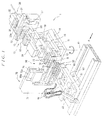
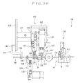
- the apparatus a front view of which is shown in FIG. 30 , is a rubber plug fitting apparatus.
- the rubber plug fitting apparatus 100 comprises a rubber plug transfer mechanism 110 and an electrical wire insertion device 120.
- the rubber plug transfer mechanism 110 comprises a rubber plug holding part 111 which holds a rubber plug S that is fed through a tube by compressed air or the like, and a middle pin 113 for transferring the rubber plug S held in the rubber plug holding part 111 to a fitting pin 112 which is arranged to transport the transferred rubber plug S.
- the rubber plug S held in the rubber plug holding part 111 is held by the middle pin 113 being passed through the rubber plug S, and the rubber plug S is fitted over and transferred to the fitting pin 112 in a transfer position A.
- the rubber plug S is then transported to a fitting position B by a rotary pin holder 114 rotating the fitting pin 112 through 180°.
- the electrical wire insertion device 120 comprises a rubber plug holder 121, an electrical wire guide 122, an anti-buckling guide 123, and an electrical wire clamp 124.
- the rubber plug holder 121 is used to hold the rubber plug S that is transported to the fitting position B by the fitting pin 112 and to fit this rubber plug on an electrical wire W.
- the rubber plug holder 121 comprises a chuck cylinder 126 and a pair of gripping arms 127 (left and right gripping arms) to be opened and closed by the chuck cylinder 126.
- Semicircular grooves 128 that have the same shape as the rubber plug S are respectively formed at the tip end portions of the individual gripping arms 127. When the two gripping arms 127 are closed, the semicircular grooves 128 form a circular hole that accommodates and holds the rubber plug S that is fitted over the fitting pin 112.
- the chuck cylinder 126 is fastened to a movable base stand 132 that can move in the horizontal direction (left-right direction in FIG. 30 ) along a guide rail 131 fastened to a base stand 130.
- the electrical wire guide 122 is installed facing the gripping arms 127 of the rubber plug holder 121, and is used to position and hold the tip end part T of the electrical wire W by causing this tip end part T to coincide with the axial core of the fitting pin 112.
- the electrical wire guide 122 comprises a chuck cylinder 134 and a pair of gripping arms 135 (left and right gripping arms) to be opened and closed by the chuck cylinder 134.
- Semicircular grooves 136 having a radius which is such that the total of the respective radii is slightly larger than the external diameter of the electrical wire W are respectively formed at the tip end portions of the individual gripping arms 135. Moreover, when the two gripping arms 135 are closed, the semicircular grooves 136 of the two gripping arms 135 form a circular hole that holds the tip end part T of the electrical wire W by allowing this tip end part T to be fitted with play inside the hole.
- the chuck cylinder 134 is fastened to the movable base stand 132.
- the anti-buckling guide 123 is used to hold the electrical wire W between the electrical wire guide 122 and the electrical wire clamp 124 that is installed away from the electrical wire guide 122 and to prevent the electrical wire W from drooping and buckling.
- the anti-buckling guide 123 comprises a chuck cylinder 138 and a pair of gripping arms 139 (left and right gripping arms) to be opened and closed by the chuck cylinder 138.
- Semicircular grooves 140 having a radius which is such that the total of the respective radii is slightly larger than the external diameter of the electrical wire W are respectively formed at the tip end portions of the individual gripping arms 139.
- the semicircular grooves 140 of the two gripping arms 139 form a circular hole that holds the electrical wire W by allowing this electrical wire to be fitted with play inside the hole.
- the chuck cylinder 138 is fastened to the base stand 130, so that there is no movement of this cylinder in the horizontal direction.
- the electrical wire clamp 124 comprises a pair of gripping arms 143 (left and right gripping arms) pivoted about a supporting shaft 142 that is fastened to the base stand 130.
- Semicircular grooves (not shown in the figure) having a radius which is such that the total of the respective radii is the same as the external diameter of the electrical wire W are respectively formed at the tip end portions of the individual gripping arms 143 in a manner facing each other. Furthermore, when the two gripping arms 143 are closed, the semicircular grooves of the two gripping arms 143 form a circular hole that grips the electrical wire W.
- the two gripping arms 143 are opened and closed by an air cylinder (not shown in the figure) that is fastened to the base stand 130.
- the electrical wire W is held by the electrical wire guide 122, anti-buckling guide 123, and electrical wire clamp 124, and the electrical wire W and the fitting pin 112 are disposed in a straight line.
- an electrical wire insertion hole (not shown in the figure) that allows the insertion of the tip end part T of the electrical wire W is formed at the tip end portion of the fitting pin 112, and the electrical wire W and fitting pin 112 are disposed such that this electrical wire insertion hole and the tip end part T of the electrical wire W face each other.
- the movable base stand 132 is then moved toward the base stand 130 so that the rubber plug holder 121 is caused to move, together with the fitting pin 112, in the direction approaching the electrical wire W, thus inserting the tip end part T of the electrical wire W into the electrical wire insertion hole in the fitting pin 112 to a specified length.
- the fitting pin 112 is caused to move in the direction away from the electrical wire W without moving the rubber plug holder 121. If this is done, because the rubber plug S is held by the rubber plug holder 121, the fitting pin 112 is removed from the rubber plug S, so that the rubber plug S is fitted on the electrical wire W at a specified location.
- the rubber plug fitting apparatus 100 shown in FIG. 30 by using a construction in which the rubber plug S is fitted over the fitting pin 112 having an electrical wire insertion hole formed therein, and the tip end part T of the electrical wire W being then inserted into the electrical wire insertion hole in the fitting pin 112, the insertion resistance during the insertion of the electrical wire W into the rubber plug S can be reduced so that the buckling of the electrical wire W can be prevented.
- the rubber plug fitting apparatus 100 shown in FIG. 30 when the electrical wire W is to be held by the electrical wire guide 122 and anti-buckling guide 123, it is necessary to manually perform the setting of the electrical wire W on the semicircular grooves 136 of the gripping arms 135 of the electrical wire guide 122 and the setting of the electrical wire W on the semicircular grooves 140 of the gripping arms 139 of the anti-buckling guide 123. Accordingly, the rubber plug fitting apparatus 100 has a problem in that it is difficult to increase the operation efficiency.
- the present invention was devised to solve the problem of the prior art described above. It is an object of the present invention to provide a sealing member fitting apparatus and method which can automatically perform the setting of an electrical wire in an electrical wire covering end part guide device that performs the positioning of the central axis of the covering end part of the electrical wire with the central axis of a sealing member.
- the sealing member fitting apparatus of claim 1 provides a sealing member fitting apparatus comprising:
- the sealing member fitting apparatus of claim 2 is the sealing member fitting apparatus according to claim 1, wherein the electrical wire insertion guide device has an electrical wire covering end part holding unit for holding the covering end part of the electrical wire when the electrical wire is clamped by the electrical wire clamping device, and an electrical wire intermediate part holding unit for holding the electrical wire between its lead-out part and its covering end part when the electrical wire is clamped by the electrical wire clamping device.
- the electrical wire insertion guide device has a construction in which the holding of the electrical wire that is clamped by the electrical wire clamping device is performed at the lead-out part of this electrical wire that is led out from the electrical wire clamping device.
- the setting of the electrical wires in the electrical wire insertion guide device can be performed automatically. This is particularly effective when electrical wires having a small external diameter are set in the electrical wire insertion guide device.
- the sealing member fitting apparatus is constructed such that the electrical wire insertion guide device has an electrical wire covering end part holding unit which holds the covering end part of the electrical wire clamped by the electrical wire clamping device, and an electrical wire intermediate part holding unit which holds the electrical wire clamped by the electrical wire clamping device between the lead-out part and the covering end part.
- the electrical wire intermediate part holding unit holds the area between the lead-out part and the covering end part of the electrical wire that is clamped by the electrical wire clamping device, so that buckling of the electrical wire can be prevented. This is particularly effective when an electrical wire having a small external diameter is set in the electrical wire insertion guide device.
- the method of fitting a sealing member as claimed in claim 3 provides a method of fitting a sealing member comprising the steps of:
- the method of claim 4 is the method according to claim 3, providing the electrical wire insertion guide device with an electrical wire covering end part holding unit which holds the covering end part of the electrical wire when the electrical wire is clamped by the electrical wire clamping device, and an electrical wire intermediate part holding unit which holds the electrical wire between its lead-out part and its covering end part when the electrical wire is clamped by the electrical wire clamping device;
- the side away from the viewer in FIG. 1 is defined as the rear side, and the side toward the viewer is defined as the front side.
- the side on which a first member approaches an electrical wire insertion guide device or sealing member holding device is defined as the front side, and the side opposite of that is defined as the rear side.
- FIGS. 4 , 6 , and 8 for the convenience of description, illustration of an intermediate part upper holding piece and covering end part upper holding piece is omitted.
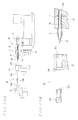
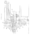
- the sealing member fitting apparatus 1 shown in FIG. 1 is used in an automated terminal treatment apparatus that is employed for the same purpose as the automated electrical wire terminal treatment apparatus shown in FIG. 30 , and comprises a sealing member transfer device 10, a sealing member holding device 30, an electrical wire supporting member 40, an electrical wire supporting member setting jig 50, an electrical wire clamping device 60, and an electrical wire insertion guide device 70.
- the sealing member holding device 30 is disposed to the rear side of the sealing member transfer device 10, and comprises a sealing member holding part 31 which holds a plurality of sealing members S that are sent from a sealing member supply source (not shown in the figures), and a seal pressing member 32 which presses the plurality of held sealing members S forward from the rear during the transfer of the sealing members S (see FIG. 11B ).
- a plurality of through-holes 31a (see FIGS. 9A and 9B ) that pass through in the forward-rearward direction and that can respectively hold the plurality of sealing members S are formed in the sealing member holding part 31.
- a tapered surface 31b for facilitating the insertion of a sealing member S is formed at the rear end edge of each of the through-holes 31a.
- a plurality of pressing parts 32a that respectively press the plurality of sealing members S are provided on the seal pressing member 32.
- a receiving hole 32b that can receive a cylindrical body 17 and a guide member 20 is formed in each of the pressing parts 32a from the front toward the rear.
- the seal pressing member 32 is made movable in the forward-rearward direction by a pressing member cylinder 33.
- one end portion thereof is supported in a pivotable manner on an electrical wire transport conveyer 41 that is installed to the front side of the sealing member transfer device 10, and the other end portion is designed to support a plurality of electrical wires W.
- the electrical wire transport conveyer 41 is designed to move in the left-right direction indicated by arrow A in FIG. 1 and to successively transport the electrical wires W.
- the electrical wire supporting member setting jig 50 is installed on the electrical wire transport conveyer 41, and is provided, on the upper surface thereof, with a supporting part 51 that supports the electrical wire supporting member 40 in an initial state with the sealing member transfer device 10 being located in a sealing member fitting position.
- the electrical wire clamping device 60 is installed on the rear end portion of the electrical wire supporting member setting jig 50.
- the electrical wire clamping device 60 comprises a clamping part 62 that clamps a plurality of electrical wires W in the vicinity of the covering end parts thereof at a specified pitch.
- An electrical wire introduction part 61 is provided to the front side of the clamping part 62 and has a plurality of electrical wire introduction grooves 61 a.
- a pair of these devices may be installed on a base plate part 11 that is supported in a manner capable of pivoting in the arrow directions in FIG. 1 , and are designed such that each of these sealing member transfer devices 10 can switch between a sealing member receiving position which faces the sealing member holding device 30 and the sealing member fitting position which faces the electrical wire clamping device 60.
- the base plate part 11 pivots such that when one of the sealing member transfer devices 10 is located in the sealing member receiving position facing the sealing member holding device 30, the other sealing member transfer device 10 is always located in the sealing member fitting position facing the electrical wire clamping device 60.
- Each sealing member transfer device 10 comprises a first member 13 that can advance and retract, a plurality of cylindrical bodies 17 that advance and retract by being installed inside the first member 13 and that protrude from the first member 13 in the advanced position but are accommodated inside the first member 13 in the retracted position, and a plurality of guide members 20 that advance and retract by being respectively disposed inside the cylindrical bodies 17 and that protrude from the cylindrical bodies 17 in the advanced position but are accommodated in the cylindrical bodies 17 in the retracted position.
- the first member 13 has a plurality of through-holes 13a (see FIGS. 9A and 9B ) that pass through in the forward-rearward direction and that can respectively receive the plurality of cylindrical bodies 17. Sealing member receiving recessed parts 13b are formed at the front ends of the respective through-holes 13a and can respectively receive sealing members S.
- the first member 13 is attached to a first member supporting plate 12, and the first member supporting plate 12 is made movable in the forward-rearward direction by a first member cylinder 14.
- each of the cylindrical bodies 17 is a cylindrical body having a through-hole 17a (see FIGS. 9A and 9B ) that passes through in the forward-rearward direction and can receive a guide member 20.
- the rear end portions of these cylindrical bodies 17 are fastened to a cylindrical body supporting member 15.
- the respective cylindrical bodies 17 are passed through the through-holes 13a in the first member 13.
- the cylindrical body supporting member 15 is made movable in the forward-rearward direction by a cylindrical body cylinder 16.
- each of the guide members 20 is constructed from a rod-form body whose front end is formed as a tapered circular conic-shaped guide part, and the rear end portion is fastened to a guide member supporting member 18.
- the respective guide members 20 are passed through the through-holes 17a in the respective cylindrical bodies 17.
- the guide member supporting member 18 is made movable in the forward-rearward direction by a guide member cylinder 19.
- the guide members 20 and cylindrical bodies 17 enter the hollow parts Sa of the sealing members S that are held in the sealing member holding part 31, and receive and hold the sealing members on the outer circumferential surfaces of the cylindrical bodies 17. Then, while the position of this sealing member transfer device 10 is subsequently switched to the sealing member fitting position, the first member 13 and guide members 20 retract (see FIG. 14B ), and in this sealing member fitting position, the first member 13 advances again accompanied by the sealing members S, thus receiving the covering end parts of positioned electrical wires W inside the cylindrical bodies 17 (see FIG. 24 ). Afterward, the sealing members S on the cylindrical bodies 17 are transferred onto the covering end parts of the electrical wires W by causing only the cylindrical bodies 17 to retract into the first member 13 (see FIG. 26 ).
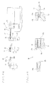
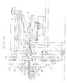
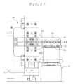
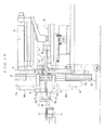
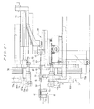
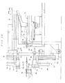
- the electrical wire insertion guide device 70 is installed to the rear side of the electrical wire clamping device 60, and comprises an advancing and retracting base part 71 that can move in the forward-rearward direction, a pair of ascending and descending base parts 72a and 72b attached to the advancing and retracting base part 71 in a manner capable of moving up and down, an electrical wire intermediate part holding unit 73 attached to the ascending and descending base parts 72a and 72b, and an electrical wire covering end part holding unit 74 similarly attached to the ascending and descending base parts 72a and 72b as shown in FIGS. 2 to 6 .
- the advancing and retracting base part 71 is formed substantially in the shape of the letter "C" as viewed from the forward-rearward direction, and is installed with the open side thereof facing toward the electrical wires W that are clamped by the electrical wire clamping device 60. Furthermore, as is shown in FIG. 3 , the advancing and retracting base part 71 is installed so as to be movable in the forward-rearward direction with respect to a base B by means of an advancing and retracting cylinder 75 which is fastened to a base stand D that is installed in an upright attitude on the base B. Moreover, a push-in piece 82 for pushing in two pushing pins 83 (described later) is installed on the side surface of the base stand D.
- the respective ascending and descending base parts 72a and 72b are installed so as to be movable in the vertical direction with respect to the advancing and retracting base part 71 by means of ascending and descending cylinders 76 that are respectively fastened to the end portions of the advancing and retracting base part 71 formed substantially in the shape of the letter "C.”
- electrical wire holding unit attachment plates 80a and 80b each having advancing and retracting rod insertion holes 79 that extend in the forward-rearward direction formed in two locations thereof, are respectively fastened to the ascending and descending base parts 72a and 72b.
- the electrical wire intermediate part holding unit 73 comprises an intermediate part upper holding piece 73a and an intermediate part lower holding piece 73b. Furthermore, the intermediate part upper holding piece 73a and intermediate part lower holding piece 73b are capable of opening and closing in the vertical direction by forming a pair.
- a plurality of electrical wire receiving grooves 77b that extend in the forward-rearward direction are formed in the upper surface of the intermediate part lower holding piece 73b from the central portion to one end portion thereof.
- the electrical wire receiving grooves 77b are formed at the same pitch as the electrical wires W that are clamped in the electrical wire clamping device 60.
- a plurality of electrical wire retaining parts 78 that face the respective electrical wire receiving grooves 77b in the intermediate part lower holding piece 73b are formed on the undersurface of the intermediate part upper holding piece 73a from the central portion to one end portion thereof Furthermore, circular arc-form recessed parts 77a that are cut out in a circular arc shape as seen from the forward-rearward direction are formed in the lower end portions of the respective electrical wire retaining parts 78.
- a plurality of holding holes 91a that can hold the electrical wires W in a slidable manner are demarcated by the respective recessed parts 77a in the intermediate part upper holding piece 73a and the respective electrical wire receiving grooves 77b in the intermediate part lower holding piece 73b.
- the respective holding holes 91a are designed such that the central axes of the held electrical wires W can be respectively positioned substantially coaxially with the central axes of the cylindrical bodies 17 of the sealing member transfer device 10 that is located in the sealing member fitting position. Furthermore, the electrical wire intermediate part holding unit 73 is placed in a closed state as a result of the undersurface of the intermediate part upper holding piece 73a and the upper surface of the intermediate part lower holding piece 73b contacting each other when the intermediate part upper holding piece 73a and intermediate part lower holding piece 73b are closed.
- each of two advancing and retracting rods 81 that extend in the forward-rearward direction is fastened to each of the rear surfaces of the intermediate part upper holding piece 73a and intermediate part lower holding piece 73b.
- the respective advancing and retracting rods 81 of the intermediate part lower holding piece 73b are passed through the respective advancing and retracting rod insertion holes 79 in the lower-side electrical wire holding unit attachment plate 80b in a slidable manner.
- the intermediate part lower holding piece 73b is attached to the lower-side ascending and descending base part 72b. Furthermore, as is shown in FIG.
- the intermediate part lower holding piece 73b and electrical wire holding unit attachment plate 80b are linked by a tension spring 85 held in tension.
- a pushing plate 84 is attached to the other end portions of the two advancing and retracting rods 81 that are passed through the advancing and retracting rod insertion holes 79.
- a pushing pin 83 that extends in the forward-rearward direction is disposed at one end portion of this pushing plate 84. Then, the intermediate part lower holding piece 73b is moved forward with respect to the ascending and descending base part 72b as a result of the pushing pin 83 of the pushing plate 84 being pushed in toward the front as shown in FIGS. 5 and 6 . Then, when this pushing of the pushing pin 83 is released, the intermediate part lower holding piece 73b is moved toward the ascending and descending base part 72b by tension of the tension spring 85.
- the respective advancing and retracting rods 81 of the intermediate part upper holding piece 73a are passed through the respective advancing and retracting rod insertion holes 79 in the upper-side electrical wire holding unit attachment plate 80a in a slidable manner.
- the intermediate part upper holding piece 73a is attached to the upper-side ascending and descending base part 72a.
- the intermediate part upper holding piece 73a and electrical wire holding unit attachment plate 80a are linked by a tension spring (not shown in the figures) that is held in tension.
- a pushing plate 84 is attached to the other end portions of the two advancing and retracting rods 81 that are passed through the advancing and retracting rod insertion holes 79. Furthermore, a pushing pin 83 that extends in the forward-rearward direction is disposed at one end portion of this pushing plate 84. Then, the intermediate part upper holding piece 73a is moved forward with respect to the ascending and descending base part 72a as a result of the pushing pin 83 of the pushing plate 84 being pushed in toward the front. Moreover, when this pushing of the pushing pin 83 is released, the intermediate part upper holding piece 73a is moved toward the ascending and descending base part 72a by tension of the tension spring 85.
- the electrical wire intermediate part holding unit 73 retracts so that the push-in piece 82 on the base stand D is disposed in a position where the end surfaces of the two pushing pins 83 contact this push-in piece 82.
- the push-in piece 82 pushes the two pushing pins 83 forward, and this causes the two ascending and descending base parts 72a and 72b installed on the advancing and retracting base part 71 to be retracted in a state in which the retraction of the electrical wire intermediate part holding unit 73 is stopped.
- the two holding pieces 73a and 73b are moved forward with respect to the two ascending and descending base parts 72a and 72b.
- the pushing of the two pushing pins 83 by means of the push-in piece 82 is released, so that the two holding pieces 73a and 73b that have been moved forward with respect to the two ascending and descending base parts 72a and 72b are moved toward the two ascending and descending base parts 72a and 72b by the tension of the tension springs 85. Consequently, the intermediate part upper holding piece 73a and intermediate part lower holding piece 73b are moved simultaneously in the forward-rearward direction, with the respective recessed parts 77a of the intermediate part upper holding piece 73a and the respective electrical wire receiving grooves 77b of the intermediate part lower holding piece 73b being caused to face each other.
- the electrical wire covering end part holding unit 74 has a covering end part upper holding piece 87a and a covering end part lower holding piece 87b. Furthermore, the covering end part upper holding piece 87a and covering end part lower holding piece 87b are capable of opening and closing in the vertical direction by forming a pair.
- the covering end part lower holding piece 87b comprises a fastening part 88 that extends in the left-right direction and a holding part 90 that is connected to the fastening part 88 via a linking part 89 that extends upward at an inclination.
- each electrical wire receiving groove 92b is the same as the shape of each electrical wire receiving groove 77b of the intermediate part lower holding piece 73b.
- a plurality of cylindrical body receiving grooves 94b that extend in the forward-rearward direction are formed in the upper surface of the holding part 90 of the covering end part lower holding piece 87b to the rear side of the respective electrical wire receiving grooves 92b.
- a planar cutout surface 99 is formed on the upper surface of the holding part 90 of the covering end part lower holding piece 87b to the front side of the electrical wire receiving grooves 92b as shown in FIG. 4 .
- the covering end part upper holding piece 87a comprises a fastening part 88 that extends in the left-right direction and a holding part 90 that is connected to the fastening part 88 via a linking part 89 that extends downward at an inclination.
- the holding part 90 of the covering end part upper holding piece 87a comprises a first holding part 96 that is formed on the rear side and a second holding part 97 that is formed on the front side.
- a plurality of electrical wire retaining parts (not shown in the figures) that face the electrical wire receiving grooves 92b of the covering end part lower holding piece 87b are formed on the undersurface of the first holding part 96.
- the electrical wire retaining parts of the first holding part 96 have the same shape as the electrical wire retaining parts 78 of the intermediate part upper holding piece 73a.
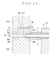
- circular arc-form recessed parts 92a (see FIG. 21 ) that are cut out in a circular arc shape as seen from the forward-rearward direction are formed in the lower end portions of the respective electrical wire retaining parts of the first holding part 96.
- the shape of the recessed parts 92a is the same as the shape of the recessed parts 77a of the electrical wire retaining parts 78 of the intermediate part upper holding piece 73a.
- the covering end part upper holding piece 87a and covering end part lower holding piece 87b are closed, the lower end portions of the respective electrical wire retaining parts of the first holding part 96 are inserted into the respective electrical wire receiving grooves 92b of the covering end part lower holding piece 87b, and the respective recessed parts 92a of the electrical wire retaining parts to be above the electrical wires W are received in the respective electrical wire receiving grooves 92b of the covering end part lower holding piece 87b.
- a plurality of holding holes 91b that can hold the electrical wires W in a slidable manner are demarcated by the respective recessed parts 92a in the first holding part 96 and the respective electrical wire receiving grooves 92b in the covering end part lower holding piece 87b.
- the respective holding holes 91b are designed such that the central axes of the held electrical wires W can be respectively positioned substantially coaxially with the central axes of the cylindrical bodies 17 of the sealing member transfer device 10 that is located in the sealing member fitting position. Furthermore, the electrical wire covering end part holding unit 74 is placed in a closed state as a result of the undersurface of the holding part 90 of the covering end part upper holding piece 87a and the upper surface of the holding part 90 of the covering end part lower holding piece 87b contacting each other when the covering end part upper holding piece 87a and covering end part lower holding piece 87b are closed.
- a plurality of cylindrical body receiving grooves 94a that face the cylindrical body receiving grooves 94b of the covering end part lower holding piece 87b are formed in the undersurface of the first holding part 96 to the rear side of the recessed parts 92a of the respective electrical wire retaining parts. Furthermore, when the undersurface of the holding part 90 of the covering end part upper holding piece 87a and the upper surface of the holding part 90 of the covering end part lower holding piece 87b contact each other as a result of the covering end part upper holding piece 87a and covering end part lower holding piece 87b being closed, a plurality of cylindrical body receiving holes 91d (see FIG.
- the respective cylindrical body receiving holes 91d are formed such that the central axes of these cylindrical body receiving holes 91d are substantially coaxial with the central axes of the cylindrical bodies 17 of the sealing member transfer device 10 that is located in the sealing member fitting position.
- the undersurface thereof is formed substantially in a planar shape.
- the undersurface of the second holding part 97 is formed so as to face the cutout surface 99 of the covering end part lower holding piece 87b.
- a plurality of circular arc-form recessed parts 99a (see FIG. 21 ) that are cut out in a circular arc shape as seen from the forward-rearward direction are formed in the undersurface of the second holding part 97.
- the shape of the recessed parts 99a is the same as the shape of the recessed parts 77a of the electrical wire retaining parts 78 of the intermediate part upper holding piece 73a.
- a plurality of holding holes 91c that can hold the electrical wires W in a slidable manner are demarcated by the respective recessed parts 99a in the second holding part 97 and the respective electrical wire receiving grooves 99b in the cutout surface 99.
- the respective holding holes 91c are designed such that the central axes of the held electrical wires W can be respectively positioned substantially coaxially with the central axes of the cylindrical bodies 17 of the sealing member transfer device 10 that is located in the sealing member fitting position.
- the fastening part 88 of the covering end part lower holding piece 87b is fastened to the electrical wire holding unit attachment plate 80b below the two advancing and retracting rod insertion holes 79.
- the covering end part lower holding piece 87b is attached to the lower-side ascending and descending base part 72b.
- the electrical wire insertion guide device 70 that is in the initial state, because the intermediate part lower holding piece 73b is driven in the direction of the electrical wire holding unit attachment plate 80b by the tension spring 85, the covering end part lower holding piece 87b and intermediate part lower holding piece 73b are placed in a contacted state.
- the respective electrical wire receiving grooves 77b in the intermediate part lower holding piece 73b and the respective electrical wire receiving grooves 92b and 99b in the covering end part lower holding piece 87b form a series of connected grooves.
- the fastening part 88 of the covering end part upper holding piece 87a is fastened to the electrical wire holding unit attachment plate 80a above the two advancing and retracting rod insertion holes 79.
- the covering end part upper holding piece 87a is attached to the upper-side ascending and descending base part 72a.
- the electrical wire insertion guide device 70 that is in the initial state, because the intermediate part upper holding piece 73a is driven in the direction of the electrical wire holding unit attachment plate 80a by the tension spring, the covering end part upper holding piece 87a and intermediate part upper holding piece 73a are placed in a contacted state.
- the respective recessed parts 77a in the intermediate part upper holding piece 73a and the respective recessed parts 92a and 99a in the covering end part upper holding piece 87a form a series of connected recessed parts.
- the covering end part upper holding piece 87a and intermediate part upper holding piece 73a are simultaneously raised or lowered as a result of the ascending and descending base part 72a being raised or lowered by the upper-side ascending and descending cylinder 76.
- the covering end part lower holding piece 87b and intermediate part lower holding piece 73b are allowed to be simultaneously raised or lowered as a result of the ascending and descending base part 72b being raised or lowered by the lower-side ascending and descending cylinder 76.
- the electrical wire intermediate part holding unit 73 and electrical wire covering end part holding unit 74 are placed in an open state as a result of the covering end part upper holding piece 87a and intermediate part upper holding piece 73a being raised and the covering end part lower holding piece 87b and intermediate part lower holding piece 73b being lowered. Moreover, the electrical wire intermediate part holding unit 73 and electrical wire covering end part holding unit 74 are placed in a closed state as a result of the covering end part upper holding piece 87a and intermediate part upper holding piece 73a being lowered and the covering end part lower holding piece 87b and intermediate part lower holding piece 73b being raised.
- the electrical wire intermediate part holding unit 73 and electrical wire covering end part holding unit 74 are simultaneously advanced or retracted as a result of the advancing and retracting base part 71 being advanced or retracted by the advancing and retracting cylinder 75.
- the electrical wire intermediate part holding unit 73 is moved toward the front with respect to the electrical wire covering end part holding unit 74 that is fastened to the ascending and descending base parts 72a and 72b as a result of the pushing pins 83 of the pushing plates 84 being pushed forward by the push-in piece 82.
- the electrical wire intermediate part holding unit 73 and electrical wire covering end part holding unit 74 are in an open state as shown in FIG. 7 . Furthermore, when the electrical wire insertion guide device 70 is in the initial state, the advancing and retracting base part 71 is located in the advanced position, and the electrical wire intermediate part holding unit 73 and electrical wire covering end part holding unit 74 are disposed as an integral unit in the electrical wire holding position to the rear side of the electrical wire clamping device 60 as shown in FIG. 8 .
- the covering end part lower holding piece 87b and intermediate part lower holding piece 73b are disposed underneath the electrical wires W that are led out from the electrical wire clamping device 60, and the respective electrical wire receiving grooves 77b in the intermediate part lower holding piece 73b are disposed underneath the lead-out parts of the respective electrical wires from the electrical wire clamping part 62.
- the covering end part upper holding piece 87a and intermediate part upper holding piece 73a are disposed above the electrical wires W that are led out from the electrical wire clamping device 60, and the respective recessed parts 77a in the intermediate part upper holding piece 73a are disposed above the lead-out parts of the respective electrical wires from the clamping part 62.
- the covering end part lower holding piece 87b and intermediate part lower holding piece 73b contact each other, and are placed in an integrated state
- the covering end part upper holding piece 87a and intermediate part upper holding piece 73a contact each other, and are placed in an integrated state.
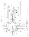
- FIGS. 9A and 9B in the initial state in which one of the sealing member transfer devices 10 is located in the sealing member receiving position which faces the sealing member holding device 30, a plurality of sealing members S that are sent from a sealing member supply source (not shown in the figures) are respectively held inside the through-holes 31a in the sealing member holding part 31. Furthermore, in this initial state, the first member 13 and cylindrical bodies 17 are located in the retracted positions, and the guide members 20 are located in the advanced position. Moreover, the seal pressing member 32 is in the retracted position.
- the first member 13 advances as shown in FIGS. 10A and 10B .
- the front end surface of the first member 13 contacts the front end surface of the sealing member holding part 31.
- the seal pressing member 32 advances as shown in FIGS. 11A and 11B .
- the front end surfaces of the respective pressing parts 32a press the rear end surfaces of the respective sealing members S, so that the front portions of the sealing members S enter the sealing member receiving recessed parts 13b of the first member 13.
- the respective guide members 20 and respective cylindrical bodies 17 advance as shown in FIGS. 12A and 12B .
- the respective guide members 20 and respective cylindrical bodies 17 enter the hollow parts Sa of the respective sealing members S that are held in the sealing member holding part 31, and receive and hold the sealing members S on the outer circumferential surfaces of the cylindrical bodies 17.
- the front ends of the respective guide members 20 are formed as tapered circular conic-shaped guide parts, these guide parts press-open the hollow parts Sa of the respective sealing members S while the respective guide members 20 and respective cylindrical bodies 17 enter the hollow parts Sa of the respective sealing members S, making this entry to be performed smoothly.
- the rear end surfaces of the respective sealing members S are pressed by the respective pressing parts 32a of the seal pressing member 32, there is no flying out of the sealing members S from the sealing member holding part 31.
- the first member 13 retracts as shown in FIGS. 13A and 13B .
- the guide members 20 also retract as shown in FIGS. 14A and 14B while the position of this sealing member transfer device 10 is switched to the sealing member fitting position.
- the sealing members S are still held on the outer circumferential surfaces of the cylindrical bodies 17.
- the base plate part 11 pivots 180° clockwise or counterclockwise in the direction indicated by the arrow in FIG. 1 .
- the electrical wire supporting member 40 is supported by the supporting part 51 of the electrical wire supporting member setting jig 50, and the respective electrical wires W are disposed in a state in which the vicinity of the covering end parts thereof are clamped by the electrical wire clamping device 60 as shown in FIG. 15 .
- the respective electrical wires W are clamped by the electrical wire clamping device 60 in a state in which the tip end parts are caused to protrude rearward from the clamping part 62.
- the electrical wire insertion guide device 70 is disposed in the electrical wire holding position in the initial state.
- the respective electrical wire receiving grooves 77b in the intermediate part lower holding piece 73b are disposed underneath the lead-out parts of the respective electrical wires W from the clamping part 62, and the respective recessed parts 77a of the intermediate part upper holding piece 73a are disposed above the lead-out parts of the respective electrical wires W from the electrical wire clamping part 62.
- the covering end part upper holding piece 87a and intermediate part upper holding piece 73a descend, and the covering end part lower holding piece 87b and intermediate part lower holding piece 73b ascend.
- the electrical wire intermediate part holding unit 73 and electrical wire covering end part holding unit 74 are closed.
- the intermediate part upper holding piece 73a and intermediate part lower holding piece 73b are positioned immediately behind the rear end surface of the clamping part 62 of the electrical wire clamping device 60. Consequently, of the electrical wires W that are clamped in the electrical wire clamping device 60, the parts that are led out from the clamping part 62 are held by the electrical wire intermediate part holding unit 73 and electrical wire covering end part holding unit 74.
- the pitch of the covering end parts of the respective electrical wires W that are led out from the clamping part 62 of the electrical wire clamping device 60 is irregular because the electrical wires hang down toward the bottom or the like. This becomes particularly prominent in cases where the external diameter of the electrical wires W is small.
- the pitch of the lead-out parts (from the clamping part 62) of the respective electrical wires W that are held in the electrical wire clamping device 60 is the same as the specified pitch at which the clamping part 62 holds the respective electrical wires W.
- the respective electrical wires W can be automatically held in a reliable manner even in cases where the external diameter of the electrical wires W is small.
- the respective holding holes 91a in the electrical wire intermediate part holding unit 73 and the respective holding holes 91b and 91c in the electrical wire covering end part holding unit 74 are placed in a state in which these holes form a series of connected holes, thus holding the respective electrical wires W in a slidable manner.
- the electrical wire intermediate part holding unit 73 and electrical wire covering end part holding unit 74 perform the positioning of the respective held electrical wires W such that the central axes of these electrical wires W are substantially coaxial with the central axes of the cylindrical bodies 17 of the sealing member transfer device 10 that is located in the sealing member fitting position.
- the advancing and retracting base part 71 retracts as shown in FIG. 18 .
- the end surfaces of the two pushing pins 83 of the electrical wire intermediate part holding unit 73 contact the push-in piece 82.
- the electrical wire intermediate part holding unit 73 and electrical wire covering end part holding unit 74 hold the respective electrical wires W in a slidable manner, the positions where the respective electrical wires W are held by the electrical wire intermediate part holding unit 73 and electrical wire covering end part holding unit 74 move toward the covering end parts of the electrical wires W.
- the electrical wire intermediate part holding unit 73 and electrical wire covering end part holding unit 74 are moved to the area between the electrical wire clamping device 60 and the sealing member fitting position, and therefore hold the portions of the respective electrical wires W between the lead-out parts from the clamping part 62 and the covering end parts. Furthermore, in the present embodiment, the electrical wire intermediate part holding unit 73 and electrical wire covering end part holding unit 74 are moved to substantially the central portion between the electrical wire clamping device 60 and the sealing member fitting position, and therefore hold substantially the central portions of the respective electrical wires W between the lead-out parts from the clamping part 62 and the covering end parts.
- the advancing and retracting base part 71 retracts further as shown in FIG. 19 .
- This causes the two pushing pins 83 to be pushed forward by the push-in piece 82, so that only the electrical wire covering end part holding unit 74 retracts in a state in which the retraction of the electrical wire intermediate part holding unit 73 is stopped.
- the electrical wire covering end part holding unit 74 is moved to the sealing member fitting position, and holds the covering end parts of the respective electrical wires W.
- the electrical wire intermediate part holding unit 73 and electrical wire covering end part holding unit 74 hold the respective electrical wires W in a state in which each of these electrical wires is made into a substantially straight line, and perform the positioning of the respective held electrical wires W such that the central axes of these electrical wires W are substantially coaxial with the central axes of the cylindrical bodies 17 of the sealing member transfer device 10 that is located in the sealing member fitting position. Consequently, the electrical wire covering end part holding unit 74 can accurately perform the positioning of the covering end parts of the electrical wires W with respect to the cylindrical bodies 17 holding the sealing members S.
- the first member 13 advances again accompanied by the sealing members S and cylindrical bodies 17.
- the tip end portions of the respective cylindrical bodies 17 are inserted into the respective cylindrical body receiving holes 91d in the electrical wire covering end part holding unit 74.
- the first member 13 advances further accompanied by the sealing members S and cylindrical bodies 17 as shown in FIG. 22 . Consequently, the tip end portions of the cylindrical bodies 17 push the electrical wire covering end part holding unit 74 forward. In this case, the position where each of the electrical wires W is held by the electrical wire covering end part holding unit 74 is moved to the area between the part led out from the clamping part 62 and the covering end part, so that the covering end parts of the respective electrical wires W are received inside the cylindrical bodies 17.
- the first member 13 advances further accompanied by the sealing members S and cylindrical bodies 17 as shown in FIG. 23 .
- the tip end portions of the cylindrical bodies 17 push the electrical wire covering end part holding unit 74 and electrical wire intermediate part holding unit 73 forward. Consequently, the positions where each of the electrical wires W is held by the electrical wire covering end part holding unit 74 and electrical wire intermediate part holding unit 73 are moved further toward the part led out from the clamping part 62.
- the covering end parts of the respective electrical wires W are inserted into the cylindrical bodies 17 to a position that allows the fitting of the sealing members S that are held on the outer circumferential surfaces of the cylindrical bodies 17.
- the electrical wire intermediate part holding unit 73 and electrical wire covering end part holding unit 74 are opened as shown in FIG. 27 . This releases the holding of the respective electrical wires W performed by the electrical wire intermediate part holding unit 73 and electrical wire covering end part holding unit 74.
- contacts are subsequently connected by crimping to the covering end parts of the respective electrical wires W that have been removed.
- this sealing member transfer device 10 is returned to the initial state shown in FIGS. 9A and 9B .
- the electrical wires W can be set automatically in the electrical wire insertion guide device 70.
- the electrical wire intermediate part holding unit 73 holds the respective electrical wires W between the lead-out parts from the clamping part 62 and the covering end parts (substantially the central parts in the present embodiment) when the sealing members S are fitted on the electrical wires W, it is possible to prevent buckling of the electrical wires W. This is particularly effective when electrical wires W having a small external diameter are set in the electrical wire insertion guide device 70.
- sealing member S on the covering end part of a single electrical wire W, instead of fitting sealing members on the covering end parts of a plurality of electrical wires W.
- the sealing member transfer devices 10 are constructed so as to switch between the sealing member receiving position which faces the sealing member holding device 30 and the sealing member fitting position which faces the electrical wire clamping device 60. It is not absolutely necessary to install these devices on the base plate part 11 that is supported in a pivotable manner in the arrow direction in FIG. 1 .
- sealing member transfer devices 10 it is not necessary to install the sealing member transfer devices 10 in a pair as a single sealing member transfer device 10 may be installed instead.
Abstract
Description
- The present invention relates to a sealing member fitting apparatus and method which automatically fits a hollow sealing member on one end portion of an electrical wire.
- A prior art sealing member fitting apparatus which automatically fits a hollow sealing member on one end portion of an electrical wire is disclosed in
JP2004-42234A FIG. 30 , is a rubber plug fitting apparatus. - The rubber
plug fitting apparatus 100 comprises a rubberplug transfer mechanism 110 and an electricalwire insertion device 120. - The rubber
plug transfer mechanism 110 comprises a rubberplug holding part 111 which holds a rubber plug S that is fed through a tube by compressed air or the like, and amiddle pin 113 for transferring the rubber plug S held in the rubberplug holding part 111 to afitting pin 112 which is arranged to transport the transferred rubber plug S. - In the rubber
plug transfer mechanism 110, the rubber plug S held in the rubberplug holding part 111 is held by themiddle pin 113 being passed through the rubber plug S, and the rubber plug S is fitted over and transferred to thefitting pin 112 in a transfer position A. The rubber plug S is then transported to a fitting position B by arotary pin holder 114 rotating thefitting pin 112 through 180°. - The electrical
wire insertion device 120 comprises arubber plug holder 121, anelectrical wire guide 122, ananti-buckling guide 123, and anelectrical wire clamp 124. - The
rubber plug holder 121 is used to hold the rubber plug S that is transported to the fitting position B by thefitting pin 112 and to fit this rubber plug on an electrical wire W. Therubber plug holder 121 comprises achuck cylinder 126 and a pair of gripping arms 127 (left and right gripping arms) to be opened and closed by thechuck cylinder 126. -
Semicircular grooves 128 that have the same shape as the rubber plug S are respectively formed at the tip end portions of the individual grippingarms 127. When the two grippingarms 127 are closed, thesemicircular grooves 128 form a circular hole that accommodates and holds the rubber plug S that is fitted over thefitting pin 112. - The
chuck cylinder 126 is fastened to amovable base stand 132 that can move in the horizontal direction (left-right direction inFIG. 30 ) along aguide rail 131 fastened to abase stand 130. - The
electrical wire guide 122 is installed facing the grippingarms 127 of therubber plug holder 121, and is used to position and hold the tip end part T of the electrical wire W by causing this tip end part T to coincide with the axial core of thefitting pin 112. Theelectrical wire guide 122 comprises achuck cylinder 134 and a pair of gripping arms 135 (left and right gripping arms) to be opened and closed by thechuck cylinder 134. -
Semicircular grooves 136 having a radius which is such that the total of the respective radii is slightly larger than the external diameter of the electrical wire W are respectively formed at the tip end portions of the individual grippingarms 135. Moreover, when the two grippingarms 135 are closed, thesemicircular grooves 136 of the two grippingarms 135 form a circular hole that holds the tip end part T of the electrical wire W by allowing this tip end part T to be fitted with play inside the hole. Thechuck cylinder 134 is fastened to themovable base stand 132. - The
anti-buckling guide 123 is used to hold the electrical wire W between theelectrical wire guide 122 and theelectrical wire clamp 124 that is installed away from theelectrical wire guide 122 and to prevent the electrical wire W from drooping and buckling. Theanti-buckling guide 123 comprises achuck cylinder 138 and a pair of gripping arms 139 (left and right gripping arms) to be opened and closed by thechuck cylinder 138. -
Semicircular grooves 140 having a radius which is such that the total of the respective radii is slightly larger than the external diameter of the electrical wire W are respectively formed at the tip end portions of the individual grippingarms 139. In addition, when the two grippingarms 139 are closed, thesemicircular grooves 140 of the two grippingarms 139 form a circular hole that holds the electrical wire W by allowing this electrical wire to be fitted with play inside the hole. - The
chuck cylinder 138 is fastened to thebase stand 130, so that there is no movement of this cylinder in the horizontal direction. - The
electrical wire clamp 124 comprises a pair of gripping arms 143 (left and right gripping arms) pivoted about a supportingshaft 142 that is fastened to thebase stand 130. - Semicircular grooves (not shown in the figure) having a radius which is such that the total of the respective radii is the same as the external diameter of the electrical wire W are respectively formed at the tip end portions of the individual gripping
arms 143 in a manner facing each other. Furthermore, when the two grippingarms 143 are closed, the semicircular grooves of the two grippingarms 143 form a circular hole that grips the electrical wire W. The two grippingarms 143 are opened and closed by an air cylinder (not shown in the figure) that is fastened to thebase stand 130. - When a rubber plug S is to be fitted on an electrical wire W by the rubber
plug fitting apparatus 100, the rubber plug S that is fitted over thefitting pin 112 and transported to the fitting position B is first held by therubber plug holder 121. - Furthermore, the electrical wire W is held by the
electrical wire guide 122,anti-buckling guide 123, andelectrical wire clamp 124, and the electrical wire W and thefitting pin 112 are disposed in a straight line. Here, an electrical wire insertion hole (not shown in the figure) that allows the insertion of the tip end part T of the electrical wire W is formed at the tip end portion of thefitting pin 112, and the electrical wire W and fittingpin 112 are disposed such that this electrical wire insertion hole and the tip end part T of the electrical wire W face each other. - The
movable base stand 132 is then moved toward thebase stand 130 so that therubber plug holder 121 is caused to move, together with thefitting pin 112, in the direction approaching the electrical wire W, thus inserting the tip end part T of the electrical wire W into the electrical wire insertion hole in thefitting pin 112 to a specified length. - Moreover, only the
fitting pin 112 is caused to move in the direction away from the electrical wire W without moving therubber plug holder 121. If this is done, because the rubber plug S is held by therubber plug holder 121, thefitting pin 112 is removed from the rubber plug S, so that the rubber plug S is fitted on the electrical wire W at a specified location. - Thus, with respect to the rubber
plug fitting apparatus 100 shown inFIG. 30 , by using a construction in which the rubber plug S is fitted over thefitting pin 112 having an electrical wire insertion hole formed therein, and the tip end part T of the electrical wire W being then inserted into the electrical wire insertion hole in thefitting pin 112, the insertion resistance during the insertion of the electrical wire W into the rubber plug S can be reduced so that the buckling of the electrical wire W can be prevented. - However, in the rubber
plug fitting apparatus 100 shown inFIG. 30 , when the electrical wire W is to be held by theelectrical wire guide 122 andanti-buckling guide 123, it is necessary to manually perform the setting of the electrical wire W on thesemicircular grooves 136 of the grippingarms 135 of theelectrical wire guide 122 and the setting of the electrical wire W on thesemicircular grooves 140 of the grippingarms 139 of theanti-buckling guide 123. Accordingly, the rubberplug fitting apparatus 100 has a problem in that it is difficult to increase the operation efficiency. - The present invention was devised to solve the problem of the prior art described above. It is an object of the present invention to provide a sealing member fitting apparatus and method which can automatically perform the setting of an electrical wire in an electrical wire covering end part guide device that performs the positioning of the central axis of the covering end part of the electrical wire with the central axis of a sealing member.
- The sealing member fitting apparatus of
claim 1 provides a sealing member fitting apparatus comprising: - a sealing member holding device for holding a hollow sealing member;
- an electrical wire clamping device for clamping an electrical wire;
- a sealing member transfer device for switching between a sealing member receiving position that faces the sealing member holding device and a sealing member fitting position that faces the electrical wire clamping device so that said sealing member transfer device in the sealing member receiving position is arranged to receive and hold the sealing member that is held by the sealing member holding device, and said sealing member transfer device in the sealing member fitting position is arranged to fit said sealing member on a covering end part of the electrical wire when the electrical wire is clamped by the electrical wire clamping device; and
- an electrical wire insertion guide device for holding in a slidable manner said electrical wire when the electrical wire is clamped by the electrical wire clamping device, and which is arranged to position the central axis of the covering end part of said electrical wire substantially coaxially with the central axis of the sealing member when the sealing member is held by the sealing member transfer device located in the sealing member fitting position, wherein
- the electrical wire insertion guide device is arranged to hold a part of the electrical wire which leads out from the electrical wire clamping device, and is arranged to move to its sealing member fitting position to hold the covering end part of the electrical wire.
- Furthermore, the sealing member fitting apparatus of
claim 2 is the sealing member fitting apparatus according toclaim 1, wherein the electrical wire insertion guide device has an electrical wire covering end part holding unit for holding the covering end part of the electrical wire when the electrical wire is clamped by the electrical wire clamping device, and an electrical wire intermediate part holding unit for holding the electrical wire between its lead-out part and its covering end part when the electrical wire is clamped by the electrical wire clamping device. - In the sealing member fitting apparatus of
claim 1, the electrical wire insertion guide device has a construction in which the holding of the electrical wire that is clamped by the electrical wire clamping device is performed at the lead-out part of this electrical wire that is led out from the electrical wire clamping device. - Thus, by holding individual electrical wires at the lead-out parts of these electrical wires from the clamping device where the pitch is established, it is possible to securely perform the holding of the respective electrical wires by means of the electrical wire insertion guide device. Accordingly, the setting of the electrical wires in the electrical wire insertion guide device can be performed automatically. This is particularly effective when electrical wires having a small external diameter are set in the electrical wire insertion guide device.
- Moreover, in the sealing member fitting apparatus of
claim 2, the sealing member fitting apparatus according toclaim 1 is constructed such that the electrical wire insertion guide device has an electrical wire covering end part holding unit which holds the covering end part of the electrical wire clamped by the electrical wire clamping device, and an electrical wire intermediate part holding unit which holds the electrical wire clamped by the electrical wire clamping device between the lead-out part and the covering end part. - Accordingly, when a sealing member is fitted on an electrical wire, the electrical wire intermediate part holding unit holds the area between the lead-out part and the covering end part of the electrical wire that is clamped by the electrical wire clamping device, so that buckling of the electrical wire can be prevented. This is particularly effective when an electrical wire having a small external diameter is set in the electrical wire insertion guide device.
- The method of fitting a sealing member as claimed in
claim 3, provides a method of fitting a sealing member comprising the steps of: - holding a hollow sealing member with a sealing member holding device;
- clamping an electrical wire with an electrical wire clamping device;
- transferring the sealing member from the sealing member holding device to a sealing member transfer device in a sealing member receiving position facing the sealing member holding device;
- switching said sealing member transfer device from the sealing member receiving position to a sealing member fitting position facing the electrical wire clamping device;
- holding in a slidable manner in an electrical wire insertion guide device a part of the electrical wire which leads out from the electrical wire clamping device;
- moving the electrical wire insertion guide device to its sealing member fitting position to hold a covering end part of the electrical wire and to position the central axis of the covering end part so as to be substantially coaxial with the central axis of the sealing member; and
- fitting the sealing member on the covering end part of the electrical wire.
- Furthermore, the method of
claim 4 is the method according toclaim 3, providing the electrical wire insertion guide device with an electrical wire covering end part holding unit which holds the covering end part of the electrical wire when the electrical wire is clamped by the electrical wire clamping device, and an electrical wire intermediate part holding unit which holds the electrical wire between its lead-out part and its covering end part when the electrical wire is clamped by the electrical wire clamping device; - forming an integral unit from the electrical wire covering end part holding unit and the electrical wire intermediate part holding unit and holding the lead-out part of the electrical wire;
- moving the electrical wire covering end part holding unit to its sealing member fitting position to hold the covering end part of the electrical wire; and
- moving the electrical wire intermediate part holding unit to the area between the electrical wire clamping device and the sealing member fitting position to hold the electrical wire between the lead-out part and the covering end part.
- An embodiment of the invention will now be described, by way of example only, with reference to the accompanying drawings, in which:
-
FIG. 1 is a schematic perspective view of the sealing member fitting apparatus of the present invention; -
FIG. 2 is a front view of an electrical wire insertion guide device of the apparatus and the device is in an initial state; -
FIG. 3 is a side view of the electrical wire insertion guide device shown inFIG. 2 ; -
FIG. 4 is a plan view of the electrical wire insertion guide device shown inFIG. 2 ; -
FIG. 5 is a side view of the electrical wire insertion guide device at the time of the fitting of the sealing members; -
FIG. 6 is a plan view of the electrical wire insertion guide device shown inFIG. 5 ; -
FIG. 7 is a front view showing the initial state of the electrical wire insertion guide device that is located in an electrical wire holding position; -
FIG. 8 is a plan view of the electrical wire insertion guide device shown inFIG. 7 ; -
FIGS. 9A and 9B show the initial state of a sealing member transfer device of the apparatus and the device is located in the sealing member receiving position, withFIG. 9A being a schematic diagram of the sealing member fitting apparatus that is in this initial state, andFIG. 9B being a sectional view of essential parts; -
FIGS. 10A and 10B show a state in which a first member of the sealing member transfer device has advanced from the initial state shown inFIGS. 9A and 9B , withFIG. 10A being a schematic diagram of the sealing member fitting apparatus in this state, andFIG. 10B being a sectional view of essential parts; -
FIGS. 11A and 11B show a state in which a seal pressing member of the apparatus has advanced from the state shown inFIGS. 10A and 10B , withFIG. 11A being a schematic diagram of the sealing member fitting apparatus in this state, andFIG. 11B being a sectional view of essential parts; -
FIGS. 12A and 12B show a state in which guide members and cylindrical bodies of the sealing member transfer device have advanced from the state shown inFIGS. 11A and 11B , withFIG. 12A being a schematic diagram of the sealing member fitting apparatus in this state, andFIG. 12B being a sectional view of essential parts; -
FIGS. 13A and 13B show a state in which the first member has retracted from the state shown inFIGS. 12A and 12B , withFIG. 13A being a schematic diagram of the sealing member fitting apparatus in this state, andFIG. 13B being a sectional view of essential parts; -
FIGS. 14A and 14B show the initial state of the sealing member transfer device that is located in the sealing member fitting position, withFIG. 14A being a schematic diagram of the sealing member fitting apparatus in this state, andFIG. 14B being a sectional view of essential parts; -
FIG. 15 is a side view showing the sealing member fitting apparatus in which the electrical wire insertion guide device is in the initial state and located in the electrical wire holding position; -
FIG. 16 is a side view showing the sealing member fitting apparatus that is in a state in which an electrical wire covering end part holding unit and an electrical wire intermediate part holding unit of the electrical wire insertion guide device are closed from the initial state shown inFIG. 15 ; -
FIG. 17 is a front view showing the sealing member fitting apparatus that is in the state shown inFIG. 16 ; -
FIG. 18 is a side view showing the sealing member fitting apparatus that is in a state in which the electrical wire covering end part holding unit and electrical wire intermediate part holding unit have retracted from the state shown inFIG. 17 ; -
FIG. 19 is a side view showing the sealing member fitting apparatus that is in a state in which the electrical wire covering end part holding unit has retracted from the state shown inFIG. 18 , and the electrical wire insertion guide device is therefore located in the sealing member fitting position; -
FIG. 20 is a side view showing the sealing member fitting apparatus that is in a state in which the sealing member transfer device of the apparatus has advanced from the state shown inFIG. 19 ; -
FIG. 21 is a sectional view of essential parts in the state shown inFIG. 20 ; -
FIG. 22 is a side view showing the sealing member fitting apparatus that is in a state in which the sealing member transfer device has advanced from the state shown inFIG. 20 ; -
FIG. 23 is a side view showing the sealing member fitting apparatus that is in a state in which the sealing member transfer device has advanced further from the state shown inFIG. 22 ; -
FIG. 24 is a sectional view of essential parts in the state shown inFIG. 23 ; -
FIG. 25 is a side view showing the sealing member fitting apparatus that is in a state in which the cylindrical bodies of the sealing member transfer device have retracted from the state shown inFIG. 23 ; -
FIG. 26 is a sectional view of essential parts in the state shown inFIG. 25 ; -
FIG. 27 is a side view showing the sealing member fitting apparatus that is in a state in which the electrical wire covering end part holding unit and electrical wire intermediate part holding unit are opened from the state shown inFIG. 25 ; -
FIG. 28 is a side view showing the sealing member fitting apparatus that is in a state in which the first member of the sealing member transfer device has retracted from the state shown inFIG. 27 ; -
FIG. 29 is a sectional view of essential parts in the state shown inFIG. 28 ; and -
FIG. 30 is a front view of a rubber plug fitting apparatus according toJP2004-42234A - Next, an embodiment of the present invention will be described with reference to the figures. In the following description, the side away from the viewer in
FIG. 1 is defined as the rear side, and the side toward the viewer is defined as the front side. However, in the description of a sealing member transfer device of a sealing member fitting apparatus, the side on which a first member approaches an electrical wire insertion guide device or sealing member holding device is defined as the front side, and the side opposite of that is defined as the rear side. - In
FIGS. 4 ,6 , and8 , for the convenience of description, illustration of an intermediate part upper holding piece and covering end part upper holding piece is omitted. - The sealing member
fitting apparatus 1 shown inFIG. 1 is used in an automated terminal treatment apparatus that is employed for the same purpose as the automated electrical wire terminal treatment apparatus shown inFIG. 30 , and comprises a sealingmember transfer device 10, a sealingmember holding device 30, an electricalwire supporting member 40, an electrical wire supportingmember setting jig 50, an electricalwire clamping device 60, and an electrical wireinsertion guide device 70. - Here, the sealing
member holding device 30 is disposed to the rear side of the sealingmember transfer device 10, and comprises a sealingmember holding part 31 which holds a plurality of sealing members S that are sent from a sealing member supply source (not shown in the figures), and aseal pressing member 32 which presses the plurality of held sealing members S forward from the rear during the transfer of the sealing members S (seeFIG. 11B ). - A plurality of through-
holes 31a (seeFIGS. 9A and 9B ) that pass through in the forward-rearward direction and that can respectively hold the plurality of sealing members S are formed in the sealingmember holding part 31. Atapered surface 31b for facilitating the insertion of a sealing member S is formed at the rear end edge of each of the through-holes 31a. - Furthermore, a plurality of
pressing parts 32a (seeFIGS. 9A and 9B ) that respectively press the plurality of sealing members S are provided on theseal pressing member 32. A receivinghole 32b that can receive acylindrical body 17 and aguide member 20 is formed in each of thepressing parts 32a from the front toward the rear. Theseal pressing member 32 is made movable in the forward-rearward direction by a pressingmember cylinder 33. - Moreover, with regard to the electrical
wire supporting member 40, one end portion thereof is supported in a pivotable manner on an electricalwire transport conveyer 41 that is installed to the front side of the sealingmember transfer device 10, and the other end portion is designed to support a plurality of electrical wires W. The electricalwire transport conveyer 41 is designed to move in the left-right direction indicated by arrow A inFIG. 1 and to successively transport the electrical wires W. - In addition, the electrical wire supporting
member setting jig 50 is installed on the electricalwire transport conveyer 41, and is provided, on the upper surface thereof, with a supportingpart 51 that supports the electricalwire supporting member 40 in an initial state with the sealingmember transfer device 10 being located in a sealing member fitting position. - Furthermore, the electrical
wire clamping device 60 is installed on the rear end portion of the electrical wire supportingmember setting jig 50. The electricalwire clamping device 60 comprises a clampingpart 62 that clamps a plurality of electrical wires W in the vicinity of the covering end parts thereof at a specified pitch. An electricalwire introduction part 61 is provided to the front side of the clampingpart 62 and has a plurality of electricalwire introduction grooves 61 a. - Moreover, with regard to the sealing
member transfer device 10, a pair of these devices may be installed on abase plate part 11 that is supported in a manner capable of pivoting in the arrow directions inFIG. 1 , and are designed such that each of these sealingmember transfer devices 10 can switch between a sealing member receiving position which faces the sealingmember holding device 30 and the sealing member fitting position which faces the electricalwire clamping device 60. Thebase plate part 11 pivots such that when one of the sealingmember transfer devices 10 is located in the sealing member receiving position facing the sealingmember holding device 30, the other sealingmember transfer device 10 is always located in the sealing member fitting position facing the electricalwire clamping device 60. - Each sealing
member transfer device 10 comprises afirst member 13 that can advance and retract, a plurality ofcylindrical bodies 17 that advance and retract by being installed inside thefirst member 13 and that protrude from thefirst member 13 in the advanced position but are accommodated inside thefirst member 13 in the retracted position, and a plurality ofguide members 20 that advance and retract by being respectively disposed inside thecylindrical bodies 17 and that protrude from thecylindrical bodies 17 in the advanced position but are accommodated in thecylindrical bodies 17 in the retracted position. - Furthermore, the
first member 13 has a plurality of through-holes 13a (seeFIGS. 9A and 9B ) that pass through in the forward-rearward direction and that can respectively receive the plurality ofcylindrical bodies 17. Sealing member receiving recessedparts 13b are formed at the front ends of the respective through-holes 13a and can respectively receive sealing members S. Thefirst member 13 is attached to a firstmember supporting plate 12, and the firstmember supporting plate 12 is made movable in the forward-rearward direction by afirst member cylinder 14. - Moreover, each of the
cylindrical bodies 17 is a cylindrical body having a through-hole 17a (seeFIGS. 9A and 9B ) that passes through in the forward-rearward direction and can receive aguide member 20. The rear end portions of thesecylindrical bodies 17 are fastened to a cylindricalbody supporting member 15. The respectivecylindrical bodies 17 are passed through the through-holes 13a in thefirst member 13. - The cylindrical
body supporting member 15 is made movable in the forward-rearward direction by acylindrical body cylinder 16. - In addition, each of the
guide members 20 is constructed from a rod-form body whose front end is formed as a tapered circular conic-shaped guide part, and the rear end portion is fastened to a guidemember supporting member 18. Therespective guide members 20 are passed through the through-holes 17a in the respectivecylindrical bodies 17. The guidemember supporting member 18 is made movable in the forward-rearward direction by aguide member cylinder 19. - With reference to the sealing
member transfer device 10 when it is in the sealing member receiving position, and when thefirst member 13,cylindrical bodies 17, and guidemembers 20 are in the advanced positions (seeFIG. 12B ), theguide members 20 andcylindrical bodies 17 enter the hollow parts Sa of the sealing members S that are held in the sealingmember holding part 31, and receive and hold the sealing members on the outer circumferential surfaces of thecylindrical bodies 17. Then, while the position of this sealingmember transfer device 10 is subsequently switched to the sealing member fitting position, thefirst member 13 andguide members 20 retract (seeFIG. 14B ), and in this sealing member fitting position, thefirst member 13 advances again accompanied by the sealing members S, thus receiving the covering end parts of positioned electrical wires W inside the cylindrical bodies 17 (seeFIG. 24 ). Afterward, the sealing members S on thecylindrical bodies 17 are transferred onto the covering end parts of the electrical wires W by causing only thecylindrical bodies 17 to retract into the first member 13 (seeFIG. 26 ). - The electrical wire
insertion guide device 70 is installed to the rear side of the electricalwire clamping device 60, and comprises an advancing and retractingbase part 71 that can move in the forward-rearward direction, a pair of ascending and descendingbase parts base part 71 in a manner capable of moving up and down, an electrical wire intermediatepart holding unit 73 attached to the ascending and descendingbase parts part holding unit 74 similarly attached to the ascending and descendingbase parts FIGS. 2 to 6 . - As is shown in
FIGS. 2 to 7 , the advancing and retractingbase part 71 is formed substantially in the shape of the letter "C" as viewed from the forward-rearward direction, and is installed with the open side thereof facing toward the electrical wires W that are clamped by the electricalwire clamping device 60. Furthermore, as is shown inFIG. 3 , the advancing and retractingbase part 71 is installed so as to be movable in the forward-rearward direction with respect to a base B by means of an advancing and retractingcylinder 75 which is fastened to a base stand D that is installed in an upright attitude on the base B. Moreover, a push-inpiece 82 for pushing in two pushing pins 83 (described later) is installed on the side surface of the base stand D. - The respective ascending and descending
base parts base part 71 by means of ascending and descendingcylinders 76 that are respectively fastened to the end portions of the advancing and retractingbase part 71 formed substantially in the shape of the letter "C." In addition, electrical wire holdingunit attachment plates base parts - As is shown in
FIG. 2 , the electrical wire intermediatepart holding unit 73 comprises an intermediate partupper holding piece 73a and an intermediate partlower holding piece 73b. Furthermore, the intermediate partupper holding piece 73a and intermediate partlower holding piece 73b are capable of opening and closing in the vertical direction by forming a pair. - As is shown in
FIG. 4 , a plurality of electricalwire receiving grooves 77b that extend in the forward-rearward direction are formed in the upper surface of the intermediate partlower holding piece 73b from the central portion to one end portion thereof. Here, the electricalwire receiving grooves 77b are formed at the same pitch as the electrical wires W that are clamped in the electricalwire clamping device 60. - As is shown in
FIGS. 2 and4 , a plurality of electricalwire retaining parts 78 that face the respective electricalwire receiving grooves 77b in the intermediate partlower holding piece 73b are formed on the undersurface of the intermediate partupper holding piece 73a from the central portion to one end portion thereof Furthermore, circular arc-form recessedparts 77a that are cut out in a circular arc shape as seen from the forward-rearward direction are formed in the lower end portions of the respective electricalwire retaining parts 78. - Moreover, when the intermediate part
upper holding piece 73a and intermediate partlower holding piece 73b are closed, the lower end portions of the respective electricalwire retaining parts 78 of the intermediate partupper holding piece 73a are inserted into the respective electricalwire receiving grooves 77b of the intermediate partlower holding piece 73b, and the respective recessedparts 77a of the electricalwire retaining parts 78 to be above the electrical wires W are received in the respective electricalwire receiving grooves 77b of the intermediate partlower holding piece 73b. Then, when the undersurface of the intermediate partupper holding piece 73a and the upper surface of the intermediate partlower holding piece 73b contact each other as a result of the intermediate partupper holding piece 73a and intermediate partlower holding piece 73b being closed, a plurality of holdingholes 91a (seeFIG. 17 ) that can hold the electrical wires W in a slidable manner are demarcated by the respective recessedparts 77a in the intermediate partupper holding piece 73a and the respective electricalwire receiving grooves 77b in the intermediate partlower holding piece 73b. Therespective holding holes 91a are designed such that the central axes of the held electrical wires W can be respectively positioned substantially coaxially with the central axes of thecylindrical bodies 17 of the sealingmember transfer device 10 that is located in the sealing member fitting position. Furthermore, the electrical wire intermediatepart holding unit 73 is placed in a closed state as a result of the undersurface of the intermediate partupper holding piece 73a and the upper surface of the intermediate partlower holding piece 73b contacting each other when the intermediate partupper holding piece 73a and intermediate partlower holding piece 73b are closed. - As is shown in
FIGS. 3 and4 , one end portion of each of two advancing and retractingrods 81 that extend in the forward-rearward direction is fastened to each of the rear surfaces of the intermediate partupper holding piece 73a and intermediate partlower holding piece 73b. Then, the respective advancing and retractingrods 81 of the intermediate partlower holding piece 73b are passed through the respective advancing and retracting rod insertion holes 79 in the lower-side electrical wire holdingunit attachment plate 80b in a slidable manner. As a result, the intermediate partlower holding piece 73b is attached to the lower-side ascending and descendingbase part 72b. Furthermore, as is shown inFIG. 4 , the intermediate partlower holding piece 73b and electrical wire holdingunit attachment plate 80b are linked by atension spring 85 held in tension. Moreover, a pushingplate 84 is attached to the other end portions of the two advancing and retractingrods 81 that are passed through the advancing and retracting rod insertion holes 79. In addition, a pushingpin 83 that extends in the forward-rearward direction is disposed at one end portion of this pushingplate 84. Then, the intermediate partlower holding piece 73b is moved forward with respect to the ascending and descendingbase part 72b as a result of the pushingpin 83 of the pushingplate 84 being pushed in toward the front as shown inFIGS. 5 and6 . Then, when this pushing of the pushingpin 83 is released, the intermediate partlower holding piece 73b is moved toward the ascending and descendingbase part 72b by tension of thetension spring 85. - Furthermore, the respective advancing and retracting
rods 81 of the intermediate partupper holding piece 73a are passed through the respective advancing and retracting rod insertion holes 79 in the upper-side electrical wire holdingunit attachment plate 80a in a slidable manner. As a result, the intermediate partupper holding piece 73a is attached to the upper-side ascending and descendingbase part 72a. Moreover, as in the case with the intermediate partlower holding piece 73b, the intermediate partupper holding piece 73a and electrical wire holdingunit attachment plate 80a are linked by a tension spring (not shown in the figures) that is held in tension. In addition, a pushingplate 84 is attached to the other end portions of the two advancing and retractingrods 81 that are passed through the advancing and retracting rod insertion holes 79. Furthermore, a pushingpin 83 that extends in the forward-rearward direction is disposed at one end portion of this pushingplate 84. Then, the intermediate partupper holding piece 73a is moved forward with respect to the ascending and descendingbase part 72a as a result of the pushingpin 83 of the pushingplate 84 being pushed in toward the front. Moreover, when this pushing of the pushingpin 83 is released, the intermediate partupper holding piece 73a is moved toward the ascending and descendingbase part 72a by tension of thetension spring 85. - Here, when the advancing and retracting
base part 71 is retracted in a state in which the intermediate partupper holding piece 73a and intermediate partlower holding piece 73b are closed, the electrical wire intermediatepart holding unit 73 retracts so that the push-inpiece 82 on the base stand D is disposed in a position where the end surfaces of the two pushingpins 83 contact this push-inpiece 82. Then, when the advancing and retractingbase part 71 is retracted further in this state, the push-inpiece 82 pushes the two pushingpins 83 forward, and this causes the two ascending and descendingbase parts base part 71 to be retracted in a state in which the retraction of the electrical wire intermediatepart holding unit 73 is stopped. As a result, the two holdingpieces base parts base part 71 is caused to advance, the pushing of the two pushingpins 83 by means of the push-inpiece 82 is released, so that the two holdingpieces base parts base parts upper holding piece 73a and intermediate partlower holding piece 73b are moved simultaneously in the forward-rearward direction, with the respective recessedparts 77a of the intermediate partupper holding piece 73a and the respective electricalwire receiving grooves 77b of the intermediate partlower holding piece 73b being caused to face each other. - As is shown in
FIGS. 2 and3 , the electrical wire covering endpart holding unit 74 has a covering end partupper holding piece 87a and a covering end partlower holding piece 87b. Furthermore, the covering end partupper holding piece 87a and covering end partlower holding piece 87b are capable of opening and closing in the vertical direction by forming a pair. - As is shown in
FIG. 2 , the covering end partlower holding piece 87b comprises afastening part 88 that extends in the left-right direction and a holdingpart 90 that is connected to thefastening part 88 via a linkingpart 89 that extends upward at an inclination. - As is shown in
FIG. 4 , a plurality of electricalwire receiving grooves 92b that extends in the forward-rearward direction are formed in the upper surface of the holdingpart 90 of the covering end partlower holding piece 87b. Here, the shape of each electricalwire receiving groove 92b is the same as the shape of each electricalwire receiving groove 77b of the intermediate partlower holding piece 73b. Furthermore, a plurality of cylindricalbody receiving grooves 94b (seeFIG. 21 ) that extend in the forward-rearward direction are formed in the upper surface of the holdingpart 90 of the covering end partlower holding piece 87b to the rear side of the respective electricalwire receiving grooves 92b. Moreover, aplanar cutout surface 99 is formed on the upper surface of the holdingpart 90 of the covering end partlower holding piece 87b to the front side of the electricalwire receiving grooves 92b as shown inFIG. 4 . In addition, a plurality of electricalwire receiving grooves 99b, that are integral with respective electricalwire receiving grooves 92b, are formed in the upper surface of thecutout surface 99. - As is shown in
FIG. 2 , the covering end partupper holding piece 87a comprises afastening part 88 that extends in the left-right direction and a holdingpart 90 that is connected to thefastening part 88 via a linkingpart 89 that extends downward at an inclination. As is shown inFIG. 3 , the holdingpart 90 of the covering end partupper holding piece 87a comprises a first holdingpart 96 that is formed on the rear side and a second holdingpart 97 that is formed on the front side. - A plurality of electrical wire retaining parts (not shown in the figures) that face the electrical
wire receiving grooves 92b of the covering end partlower holding piece 87b are formed on the undersurface of the first holdingpart 96. The electrical wire retaining parts of the first holdingpart 96 have the same shape as the electricalwire retaining parts 78 of the intermediate partupper holding piece 73a. Furthermore, circular arc-form recessedparts 92a (seeFIG. 21 ) that are cut out in a circular arc shape as seen from the forward-rearward direction are formed in the lower end portions of the respective electrical wire retaining parts of the first holdingpart 96. The shape of the recessedparts 92a is the same as the shape of the recessedparts 77a of the electricalwire retaining parts 78 of the intermediate partupper holding piece 73a. - Moreover, when the covering end part
upper holding piece 87a and covering end partlower holding piece 87b are closed, the lower end portions of the respective electrical wire retaining parts of the first holdingpart 96 are inserted into the respective electricalwire receiving grooves 92b of the covering end partlower holding piece 87b, and the respective recessedparts 92a of the electrical wire retaining parts to be above the electrical wires W are received in the respective electricalwire receiving grooves 92b of the covering end partlower holding piece 87b. Then, when the undersurface of the holdingpart 90 of the covering end partupper holding piece 87a and the upper surface of the holdingpart 90 of the covering end partlower holding piece 87b contact each other as a result of the covering end partupper holding piece 87a and covering end partlower holding piece 87b being closed, a plurality of holdingholes 91b (seeFIG. 21 ) that can hold the electrical wires W in a slidable manner are demarcated by the respective recessedparts 92a in the first holdingpart 96 and the respective electricalwire receiving grooves 92b in the covering end partlower holding piece 87b. The respective holdingholes 91b are designed such that the central axes of the held electrical wires W can be respectively positioned substantially coaxially with the central axes of thecylindrical bodies 17 of the sealingmember transfer device 10 that is located in the sealing member fitting position. Furthermore, the electrical wire covering endpart holding unit 74 is placed in a closed state as a result of the undersurface of the holdingpart 90 of the covering end partupper holding piece 87a and the upper surface of the holdingpart 90 of the covering end partlower holding piece 87b contacting each other when the covering end partupper holding piece 87a and covering end partlower holding piece 87b are closed. - In addition, a plurality of cylindrical
body receiving grooves 94a (seeFIG. 21 ) that face the cylindricalbody receiving grooves 94b of the covering end partlower holding piece 87b are formed in the undersurface of the first holdingpart 96 to the rear side of the recessedparts 92a of the respective electrical wire retaining parts. Furthermore, when the undersurface of the holdingpart 90 of the covering end partupper holding piece 87a and the upper surface of the holdingpart 90 of the covering end partlower holding piece 87b contact each other as a result of the covering end partupper holding piece 87a and covering end partlower holding piece 87b being closed, a plurality of cylindricalbody receiving holes 91d (seeFIG. 21 ) which allow the insertion of the tip end portions of thecylindrical bodies 17 of the sealingmember transfer device 10 are demarcated by the respective cylindricalbody receiving grooves 94a in the first holdingpart 96 and the respective cylindricalbody receiving grooves 94b in the covering end partlower holding piece 87b. The respective cylindricalbody receiving holes 91d are formed such that the central axes of these cylindricalbody receiving holes 91d are substantially coaxial with the central axes of thecylindrical bodies 17 of the sealingmember transfer device 10 that is located in the sealing member fitting position. - With regard to the second holding
part 97, the undersurface thereof is formed substantially in a planar shape. The undersurface of the second holdingpart 97 is formed so as to face thecutout surface 99 of the covering end partlower holding piece 87b. A plurality of circular arc-form recessedparts 99a (seeFIG. 21 ) that are cut out in a circular arc shape as seen from the forward-rearward direction are formed in the undersurface of the second holdingpart 97. The shape of the recessedparts 99a is the same as the shape of the recessedparts 77a of the electricalwire retaining parts 78 of the intermediate partupper holding piece 73a. Furthermore, when the undersurface of the second holdingpart 97 of the covering end partupper holding piece 87a and thecutout surface 99 of the covering end partlower holding piece 87b contact each other as a result of the covering end partupper holding piece 87a and covering end partlower holding piece 87b being closed, a plurality of holdingholes 91c (seeFIG. 21 ) that can hold the electrical wires W in a slidable manner are demarcated by the respective recessedparts 99a in the second holdingpart 97 and the respective electricalwire receiving grooves 99b in thecutout surface 99. The respective holdingholes 91c are designed such that the central axes of the held electrical wires W can be respectively positioned substantially coaxially with the central axes of thecylindrical bodies 17 of the sealingmember transfer device 10 that is located in the sealing member fitting position. - As is shown in
FIG. 2 , thefastening part 88 of the covering end partlower holding piece 87b is fastened to the electrical wire holdingunit attachment plate 80b below the two advancing and retracting rod insertion holes 79. As a result, the covering end partlower holding piece 87b is attached to the lower-side ascending and descendingbase part 72b. In the electrical wireinsertion guide device 70 that is in the initial state, because the intermediate partlower holding piece 73b is driven in the direction of the electrical wire holdingunit attachment plate 80b by thetension spring 85, the covering end partlower holding piece 87b and intermediate partlower holding piece 73b are placed in a contacted state. In this case, the respective electricalwire receiving grooves 77b in the intermediate partlower holding piece 73b and the respective electricalwire receiving grooves lower holding piece 87b form a series of connected grooves. - The
fastening part 88 of the covering end partupper holding piece 87a is fastened to the electrical wire holdingunit attachment plate 80a above the two advancing and retracting rod insertion holes 79. As a result, the covering end partupper holding piece 87a is attached to the upper-side ascending and descendingbase part 72a. In the electrical wireinsertion guide device 70 that is in the initial state, because the intermediate partupper holding piece 73a is driven in the direction of the electrical wire holdingunit attachment plate 80a by the tension spring, the covering end partupper holding piece 87a and intermediate partupper holding piece 73a are placed in a contacted state. In this case, the respective recessedparts 77a in the intermediate partupper holding piece 73a and the respective recessedparts upper holding piece 87a form a series of connected recessed parts. - The covering end part
upper holding piece 87a and intermediate partupper holding piece 73a are simultaneously raised or lowered as a result of the ascending and descendingbase part 72a being raised or lowered by the upper-side ascending and descendingcylinder 76. Likewise, the covering end partlower holding piece 87b and intermediate partlower holding piece 73b are allowed to be simultaneously raised or lowered as a result of the ascending and descendingbase part 72b being raised or lowered by the lower-side ascending and descendingcylinder 76. Furthermore, the electrical wire intermediatepart holding unit 73 and electrical wire covering endpart holding unit 74 are placed in an open state as a result of the covering end partupper holding piece 87a and intermediate partupper holding piece 73a being raised and the covering end partlower holding piece 87b and intermediate partlower holding piece 73b being lowered. Moreover, the electrical wire intermediatepart holding unit 73 and electrical wire covering endpart holding unit 74 are placed in a closed state as a result of the covering end partupper holding piece 87a and intermediate partupper holding piece 73a being lowered and the covering end partlower holding piece 87b and intermediate partlower holding piece 73b being raised. - In addition, the electrical wire intermediate
part holding unit 73 and electrical wire covering endpart holding unit 74 are simultaneously advanced or retracted as a result of the advancing and retractingbase part 71 being advanced or retracted by the advancing and retractingcylinder 75. - Furthermore, the electrical wire intermediate
part holding unit 73 is moved toward the front with respect to the electrical wire covering endpart holding unit 74 that is fastened to the ascending and descendingbase parts pins 83 of the pushingplates 84 being pushed forward by the push-inpiece 82. - Moreover, in the electrical wire
insertion guide device 70 that is in the initial state, the electrical wire intermediatepart holding unit 73 and electrical wire covering endpart holding unit 74 are in an open state as shown inFIG. 7 . Furthermore, when the electrical wireinsertion guide device 70 is in the initial state, the advancing and retractingbase part 71 is located in the advanced position, and the electrical wire intermediatepart holding unit 73 and electrical wire covering endpart holding unit 74 are disposed as an integral unit in the electrical wire holding position to the rear side of the electricalwire clamping device 60 as shown inFIG. 8 . In this case, the covering end partlower holding piece 87b and intermediate partlower holding piece 73b are disposed underneath the electrical wires W that are led out from the electricalwire clamping device 60, and the respective electricalwire receiving grooves 77b in the intermediate partlower holding piece 73b are disposed underneath the lead-out parts of the respective electrical wires from the electricalwire clamping part 62. Likewise, the covering end partupper holding piece 87a and intermediate partupper holding piece 73a are disposed above the electrical wires W that are led out from the electricalwire clamping device 60, and the respective recessedparts 77a in the intermediate partupper holding piece 73a are disposed above the lead-out parts of the respective electrical wires from the clampingpart 62. Furthermore, as a result of the advancing and retractingbase part 71 being in the advanced position, the covering end partlower holding piece 87b and intermediate partlower holding piece 73b contact each other, and are placed in an integrated state, and the covering end partupper holding piece 87a and intermediate partupper holding piece 73a contact each other, and are placed in an integrated state. - Next, a method for fitting sealing member S on the covering end parts of electrical wires W will be described in detail with reference to the figures.
- First, as is shown in
FIGS. 9A and 9B , in the initial state in which one of the sealingmember transfer devices 10 is located in the sealing member receiving position which faces the sealingmember holding device 30, a plurality of sealing members S that are sent from a sealing member supply source (not shown in the figures) are respectively held inside the through-holes 31a in the sealingmember holding part 31. Furthermore, in this initial state, thefirst member 13 andcylindrical bodies 17 are located in the retracted positions, and theguide members 20 are located in the advanced position. Moreover, theseal pressing member 32 is in the retracted position. - Then, the
first member 13 advances as shown inFIGS. 10A and 10B . As a result, the front end surface of thefirst member 13 contacts the front end surface of the sealingmember holding part 31. - Next, the
seal pressing member 32 advances as shown inFIGS. 11A and 11B . As a result, the front end surfaces of the respectivepressing parts 32a press the rear end surfaces of the respective sealing members S, so that the front portions of the sealing members S enter the sealing member receiving recessedparts 13b of thefirst member 13. - Afterward, the
respective guide members 20 and respectivecylindrical bodies 17 advance as shown inFIGS. 12A and 12B . As a result, therespective guide members 20 and respectivecylindrical bodies 17 enter the hollow parts Sa of the respective sealing members S that are held in the sealingmember holding part 31, and receive and hold the sealing members S on the outer circumferential surfaces of thecylindrical bodies 17. At this point, because the front ends of therespective guide members 20 are formed as tapered circular conic-shaped guide parts, these guide parts press-open the hollow parts Sa of the respective sealing members S while therespective guide members 20 and respectivecylindrical bodies 17 enter the hollow parts Sa of the respective sealing members S, making this entry to be performed smoothly. Furthermore, because the rear end surfaces of the respective sealing members S are pressed by the respectivepressing parts 32a of theseal pressing member 32, there is no flying out of the sealing members S from the sealingmember holding part 31. - Then, the
first member 13 retracts as shown inFIGS. 13A and 13B . Furthermore, theguide members 20 also retract as shown inFIGS. 14A and 14B while the position of this sealingmember transfer device 10 is switched to the sealing member fitting position. In this case, the sealing members S are still held on the outer circumferential surfaces of thecylindrical bodies 17. When the position of each sealingmember transfer device 10 is switched to the sealing member fitting position, thebase plate part 11 pivots 180° clockwise or counterclockwise in the direction indicated by the arrow inFIG. 1 . - Meanwhile, in the initial state in which the sealing
member transfer device 10 shown inFIGS. 14A and 14B is located in the sealing member fitting position, the electricalwire supporting member 40 is supported by the supportingpart 51 of the electrical wire supportingmember setting jig 50, and the respective electrical wires W are disposed in a state in which the vicinity of the covering end parts thereof are clamped by the electricalwire clamping device 60 as shown inFIG. 15 . In this case, the respective electrical wires W are clamped by the electricalwire clamping device 60 in a state in which the tip end parts are caused to protrude rearward from the clampingpart 62. - Furthermore, as is shown in
FIGS. 8 and15 , the electrical wireinsertion guide device 70 is disposed in the electrical wire holding position in the initial state. In the electrical wireinsertion guide device 70 that is in the initial state, the respective electricalwire receiving grooves 77b in the intermediate partlower holding piece 73b are disposed underneath the lead-out parts of the respective electrical wires W from the clampingpart 62, and the respective recessedparts 77a of the intermediate partupper holding piece 73a are disposed above the lead-out parts of the respective electrical wires W from the electricalwire clamping part 62. - Next, as is shown in
FIGS. 16 and17 , the covering end partupper holding piece 87a and intermediate partupper holding piece 73a descend, and the covering end partlower holding piece 87b and intermediate partlower holding piece 73b ascend. As a result, the electrical wire intermediatepart holding unit 73 and electrical wire covering endpart holding unit 74 are closed. In this case, the intermediate partupper holding piece 73a and intermediate partlower holding piece 73b are positioned immediately behind the rear end surface of the clampingpart 62 of the electricalwire clamping device 60. Consequently, of the electrical wires W that are clamped in the electricalwire clamping device 60, the parts that are led out from the clampingpart 62 are held by the electrical wire intermediatepart holding unit 73 and electrical wire covering endpart holding unit 74. - Here, the pitch of the covering end parts of the respective electrical wires W that are led out from the clamping
part 62 of the electricalwire clamping device 60 is irregular because the electrical wires hang down toward the bottom or the like. This becomes particularly prominent in cases where the external diameter of the electrical wires W is small. - In contrast, the pitch of the lead-out parts (from the clamping part 62) of the respective electrical wires W that are held in the electrical
wire clamping device 60 is the same as the specified pitch at which the clampingpart 62 holds the respective electrical wires W. - Therefore, by holding the respective electrical wires W at the lead-out parts of the respective electrical wires W from the clamping
device 60 with the pitch thereof being established, the respective electrical wires W can be automatically held in a reliable manner even in cases where the external diameter of the electrical wires W is small. In this case, the respective holdingholes 91a in the electrical wire intermediatepart holding unit 73 and the respective holdingholes part holding unit 74 are placed in a state in which these holes form a series of connected holes, thus holding the respective electrical wires W in a slidable manner. Then, the electrical wire intermediatepart holding unit 73 and electrical wire covering endpart holding unit 74 perform the positioning of the respective held electrical wires W such that the central axes of these electrical wires W are substantially coaxial with the central axes of thecylindrical bodies 17 of the sealingmember transfer device 10 that is located in the sealing member fitting position. - Then, the advancing and retracting
base part 71 retracts as shown inFIG. 18 . As a result, the end surfaces of the two pushingpins 83 of the electrical wire intermediatepart holding unit 73 contact the push-inpiece 82. In this case, because the electrical wire intermediatepart holding unit 73 and electrical wire covering endpart holding unit 74 hold the respective electrical wires W in a slidable manner, the positions where the respective electrical wires W are held by the electrical wire intermediatepart holding unit 73 and electrical wire covering endpart holding unit 74 move toward the covering end parts of the electrical wires W. Then, the electrical wire intermediatepart holding unit 73 and electrical wire covering endpart holding unit 74 are moved to the area between the electricalwire clamping device 60 and the sealing member fitting position, and therefore hold the portions of the respective electrical wires W between the lead-out parts from the clampingpart 62 and the covering end parts. Furthermore, in the present embodiment, the electrical wire intermediatepart holding unit 73 and electrical wire covering endpart holding unit 74 are moved to substantially the central portion between the electricalwire clamping device 60 and the sealing member fitting position, and therefore hold substantially the central portions of the respective electrical wires W between the lead-out parts from the clampingpart 62 and the covering end parts. - Then, the advancing and retracting
base part 71 retracts further as shown inFIG. 19 . This causes the two pushingpins 83 to be pushed forward by the push-inpiece 82, so that only the electrical wire covering endpart holding unit 74 retracts in a state in which the retraction of the electrical wire intermediatepart holding unit 73 is stopped. In this case, the electrical wire covering endpart holding unit 74 is moved to the sealing member fitting position, and holds the covering end parts of the respective electrical wires W. As a result, the electrical wire intermediatepart holding unit 73 and electrical wire covering endpart holding unit 74 hold the respective electrical wires W in a state in which each of these electrical wires is made into a substantially straight line, and perform the positioning of the respective held electrical wires W such that the central axes of these electrical wires W are substantially coaxial with the central axes of thecylindrical bodies 17 of the sealingmember transfer device 10 that is located in the sealing member fitting position. Consequently, the electrical wire covering endpart holding unit 74 can accurately perform the positioning of the covering end parts of the electrical wires W with respect to thecylindrical bodies 17 holding the sealing members S. - Next, as is shown
FIGS. 20 and21 , thefirst member 13 advances again accompanied by the sealing members S andcylindrical bodies 17. As a result, the tip end portions of the respectivecylindrical bodies 17 are inserted into the respective cylindricalbody receiving holes 91d in the electrical wire covering endpart holding unit 74. - Moreover, the
first member 13 advances further accompanied by the sealing members S andcylindrical bodies 17 as shown inFIG. 22 . Consequently, the tip end portions of thecylindrical bodies 17 push the electrical wire covering endpart holding unit 74 forward. In this case, the position where each of the electrical wires W is held by the electrical wire covering endpart holding unit 74 is moved to the area between the part led out from the clampingpart 62 and the covering end part, so that the covering end parts of the respective electrical wires W are received inside thecylindrical bodies 17. - Furthermore, the
first member 13 advances further accompanied by the sealing members S andcylindrical bodies 17 as shown inFIG. 23 . As a result, the tip end portions of thecylindrical bodies 17 push the electrical wire covering endpart holding unit 74 and electrical wire intermediatepart holding unit 73 forward. Consequently, the positions where each of the electrical wires W is held by the electrical wire covering endpart holding unit 74 and electrical wire intermediatepart holding unit 73 are moved further toward the part led out from the clampingpart 62. Then, as is shown inFIG. 24 , the covering end parts of the respective electrical wires W are inserted into thecylindrical bodies 17 to a position that allows the fitting of the sealing members S that are held on the outer circumferential surfaces of thecylindrical bodies 17. - Subsequently, only the
cylindrical bodies 17 retract into thefirst member 13 as shown inFIGS. 25 and26 . As a result, the respective sealing members S on thecylindrical bodies 17 are transferred onto the covering end parts of the respective electrical wires W. Consequently, the sealing members S are automatically fitted on the covering end parts of the electrical wires W. - Then, the electrical wire intermediate
part holding unit 73 and electrical wire covering endpart holding unit 74 are opened as shown inFIG. 27 . This releases the holding of the respective electrical wires W performed by the electrical wire intermediatepart holding unit 73 and electrical wire covering endpart holding unit 74. - Finally, the
first member 13 retracts as shown inFIGS. 28 and29 . As a result, the respective electrical wires W whose covering end parts have the sealing members S fitted thereon are removed from the interior of thecylindrical bodies 17. - Furthermore, contacts (not shown in the figures) are subsequently connected by crimping to the covering end parts of the respective electrical wires W that have been removed.
- Then, this sealing
member transfer device 10 is returned to the initial state shown inFIGS. 9A and 9B . - Thus, with respect to the sealing member
fitting apparatus 1, by holding the lead-out parts of respective electrical wires W beyond the clampingdevice 60, the electrical wires W can be set automatically in the electrical wireinsertion guide device 70. - Moreover, since the electrical wire intermediate
part holding unit 73 holds the respective electrical wires W between the lead-out parts from the clampingpart 62 and the covering end parts (substantially the central parts in the present embodiment) when the sealing members S are fitted on the electrical wires W, it is possible to prevent buckling of the electrical wires W. This is particularly effective when electrical wires W having a small external diameter are set in the electrical wireinsertion guide device 70. - An embodiment of the present invention has been described above. However, the present invention is not limited to this embodiment, and various alterations or modifications can be made.
- For example, it would also be possible to fit a sealing member S on the covering end part of a single electrical wire W, instead of fitting sealing members on the covering end parts of a plurality of electrical wires W.
- Furthermore, it is sufficient if the sealing
member transfer devices 10 are constructed so as to switch between the sealing member receiving position which faces the sealingmember holding device 30 and the sealing member fitting position which faces the electricalwire clamping device 60. It is not absolutely necessary to install these devices on thebase plate part 11 that is supported in a pivotable manner in the arrow direction inFIG. 1 . - Moreover, it is not necessary to install the sealing
member transfer devices 10 in a pair as a single sealingmember transfer device 10 may be installed instead. - In addition, with regard to the electrical wire
insertion guide device 70, it would also be possible to use a construction in which a plurality of electrical wire intermediatepart holding units 73 are provided.
Claims (4)
- A sealing member fitting apparatus (1) comprising:a sealing member holding device (30) for holding a hollow sealing member (S);an electrical wire clamping device (60) for clamping an electrical wire (W);a sealing member transfer device (10) for switching between a sealing member receiving position that faces the sealing member holding device (30) and a sealing member fitting position that faces the electrical wire clamping device (60) so that said sealing member transfer device (10) in the sealing member receiving position is arranged to receive and hold the sealing member (S) that is held by the sealing member holding device (30), and said sealing member transfer device (10) in the sealing member fitting position is arranged to fit said sealing member (S) on a covering end part of the electrical wire (W) when the electrical wire (W) is clamped by the electrical wire clamping device (60); andan electrical wire insertion guide device (70) for holding in a slidable manner said electrical wire (W) when the electrical wire (W) is clamped by the electrical wire clamping device (60), and which is arranged to position the central axis of the covering end part of said electrical wire (W) substantially coaxially with the central axis of the sealing member (S) when the sealing member (S) is held by the sealing member transfer device (10) located in the sealing member fitting position, whereinthe electrical wire insertion guide device (70) is arranged to hold a part of the electrical wire (W) which leads out from the electrical wire clamping device (60), and is arranged to move to its sealing member fitting position to hold the covering end part of the electrical wire (W).
- The apparatus according to claim 1, wherein the electrical wire insertion guide device (70) has an electrical wire covering end part holding unit (74) for holding the covering end part of the electrical wire (W) when the electrical wire (W) is clamped by the electrical wire clamping device (60), and an electrical wire intermediate part holding unit (73) for holding the electrical wire (W) between its lead-out part and its covering end part when the electrical wire (W) is clamped by the electrical wire clamping device (60).
- A method of fitting a sealing member (S) comprising the steps of:holding a hollow sealing member (S) with a sealing member holding device (30);clamping an electrical wire (W) with an electrical wire clamping device (60);transferring the sealing member (S) from the sealing member holding device (30) to a sealing member transfer device (10) in a sealing member receiving position facing the sealing member holding device (30);switching said sealing member transfer device (10) from the sealing member receiving position to a sealing member fitting position facing the electrical wire clamping device (60);holding in a slidable manner in an electrical wire insertion guide device (70) a part of the electrical wire (W) which leads out from the electrical wire clamping device (60);moving the electrical wire insertion guide device (70) to its sealing member fitting position to hold a covering end part of the electrical wire (W) and to position the central axis of the covering end part so as to be substantially coaxial with the central axis of the sealing member (S); andfitting the sealing member (S) on the covering end part of the electrical wire (W).
- The method according to claim 3, including the steps ofproviding the electrical wire insertion guide device (70) with an electrical wire covering end part holding unit (74) which holds the covering end part of the electrical wire (W) when the electrical wire (W) is clamped by the electrical wire clamping device (60), and an electrical wire intermediate part holding unit (73) which holds the electrical wire (W) between its lead-out part and its covering end part when the electrical wire (W) is clamped by the electrical wire clamping device (60);forming an integral unit from the electrical wire covering end part holding unit (74) and the electrical wire intermediate part holding unit (73) and holding the lead-out part of the electrical wire (W);moving the electrical wire covering end part holding unit (74) to its sealing member fitting position to hold the covering end part of the electrical wire (W); andmoving the electrical wire intermediate part holding unit (73) to the area between the electrical wire clamping device (60) and the sealing member fitting position to hold the electrical wire (W) between the lead-out part and the covering end part.
Applications Claiming Priority (1)
| Application Number | Priority Date | Filing Date | Title |
|---|---|---|---|
| JP2006355072A JP2008167592A (en) | 2006-12-28 | 2006-12-28 | Seal member mounting apparatus |
Publications (2)
| Publication Number | Publication Date |
|---|---|
| EP1939994A2 true EP1939994A2 (en) | 2008-07-02 |
| EP1939994A3 EP1939994A3 (en) | 2010-11-17 |
Family
ID=39148830
Family Applications (1)
| Application Number | Title | Priority Date | Filing Date |
|---|---|---|---|
| EP07123628A Withdrawn EP1939994A3 (en) | 2006-12-28 | 2007-12-19 | Sealing member fitting apparatus and method |
Country Status (5)
| Country | Link |
|---|---|
| US (1) | US7810230B2 (en) |
| EP (1) | EP1939994A3 (en) |
| JP (1) | JP2008167592A (en) |
| CN (1) | CN101212114A (en) |
| SG (1) | SG144058A1 (en) |
Cited By (1)
| Publication number | Priority date | Publication date | Assignee | Title |
|---|---|---|---|---|
| WO2022058993A1 (en) * | 2020-09-21 | 2022-03-24 | Aptiv Technologies Limited | Automated wire kitting systems and methods |
Families Citing this family (6)
| Publication number | Priority date | Publication date | Assignee | Title |
|---|---|---|---|---|
| JP5088582B2 (en) * | 2008-12-23 | 2012-12-05 | 住友電装株式会社 | Cylindrical member insertion device |
| PL2320527T3 (en) * | 2009-11-09 | 2012-12-31 | Schaefer Werkzeug & Sonderma | Machine for mounting grommets |
| EP2372848B1 (en) | 2010-03-30 | 2012-11-14 | Komax Holding AG | Device and method for equipping cables with grommets |
| JP6061148B2 (en) * | 2013-11-28 | 2017-01-18 | 住友電装株式会社 | connector |
| JP6732846B2 (en) * | 2018-06-25 | 2020-07-29 | 矢崎総業株式会社 | Waterproof plug insertion device and method for manufacturing connector housing with waterproof plug |
| US11592121B2 (en) | 2020-04-16 | 2023-02-28 | Te Connectivity Solutions Gmbh | Method and device for positioning components on a cable |
Citations (1)
| Publication number | Priority date | Publication date | Assignee | Title |
|---|---|---|---|---|
| JP2004042234A (en) | 2002-07-15 | 2004-02-12 | Yazaki Corp | Rubber plug fitting method and rubber plug inserting machine |
Family Cites Families (13)
| Publication number | Priority date | Publication date | Assignee | Title |
|---|---|---|---|---|
| JPS59154783A (en) * | 1983-02-21 | 1984-09-03 | アンプ インコーポレーテッド | Apparatus for mounting hollow sealing plug on wire terminal |
| JPH073784Y2 (en) * | 1988-08-04 | 1995-01-30 | 日本オートマチツクマシン株式会社 | Seal insertion device for wire processing machine |
| GB8917145D0 (en) * | 1989-07-27 | 1989-09-13 | Amp Gmbh | Applying a bung seal to an electrical lead |
| JP2999512B2 (en) * | 1990-05-14 | 2000-01-17 | 日本端子株式会社 | How to insert a waterproof rubber stopper |
| CH689272A5 (en) * | 1993-05-06 | 1999-01-15 | Komax Holding Ag | Device for fitting sleeves of electric cables. |
| JPH0715821A (en) | 1993-06-23 | 1995-01-17 | Hitachi Sci Syst:Kk | Wire stripping machine |
| JP3630751B2 (en) * | 1995-02-08 | 2005-03-23 | タイコエレクトロニクスアンプ株式会社 | Wire guide device |
| JPH1056716A (en) * | 1996-08-09 | 1998-02-24 | Sumitomo Wiring Syst Ltd | Intermediate stripper unit |
| JPH11164434A (en) | 1997-11-12 | 1999-06-18 | Hitachi Sci Syst Ltd | Electric wire clamping mechanism of electric wire covering stripping device |
| JP3570667B2 (en) * | 1998-07-10 | 2004-09-29 | 矢崎総業株式会社 | Rubber stopper insertion device and rubber stopper insertion method |
| JP3573987B2 (en) * | 1998-12-18 | 2004-10-06 | 矢崎総業株式会社 | Rubber stopper insertion device |
| JP2001076557A (en) * | 1999-09-09 | 2001-03-23 | Mitsubishi Electric Engineering Co Ltd | Wire covering device |
| JP4358100B2 (en) * | 2004-12-27 | 2009-11-04 | タイコエレクトロニクスアンプ株式会社 | Seal member mounting device |
-
2006
- 2006-12-28 JP JP2006355072A patent/JP2008167592A/en active Pending
-
2007
- 2007-12-11 SG SG200718542-4A patent/SG144058A1/en unknown
- 2007-12-19 EP EP07123628A patent/EP1939994A3/en not_active Withdrawn
- 2007-12-20 US US11/961,055 patent/US7810230B2/en not_active Expired - Fee Related
- 2007-12-28 CN CN200710300491.1A patent/CN101212114A/en active Pending
Patent Citations (1)
| Publication number | Priority date | Publication date | Assignee | Title |
|---|---|---|---|---|
| JP2004042234A (en) | 2002-07-15 | 2004-02-12 | Yazaki Corp | Rubber plug fitting method and rubber plug inserting machine |
Cited By (1)
| Publication number | Priority date | Publication date | Assignee | Title |
|---|---|---|---|---|
| WO2022058993A1 (en) * | 2020-09-21 | 2022-03-24 | Aptiv Technologies Limited | Automated wire kitting systems and methods |
Also Published As
| Publication number | Publication date |
|---|---|
| JP2008167592A (en) | 2008-07-17 |
| EP1939994A3 (en) | 2010-11-17 |
| SG144058A1 (en) | 2008-07-29 |
| CN101212114A (en) | 2008-07-02 |
| US20080155816A1 (en) | 2008-07-03 |
| US7810230B2 (en) | 2010-10-12 |
Similar Documents
| Publication | Publication Date | Title |
|---|---|---|
| EP1939994A2 (en) | Sealing member fitting apparatus and method | |
| US4420674A (en) | Procedure and device for welding studs and similar parts to a work piece | |
| US7603768B2 (en) | Inspection apparatus for wire-processing machine | |
| EP0410416A2 (en) | Applying a bung seal to an electrical lead | |
| US20140238957A1 (en) | Spot welding cap changer | |
| JPH09290332A (en) | Rubber plug insertion device and the plug supplying method, and rubber plug insertion method | |
| CN112621148B (en) | Automatic assembly process for automobile parts | |
| JP2001328035A (en) | Device for clamping and inserting object to be inserted and assembly unit | |
| EP2460621A1 (en) | Jig for measuring size of work piece | |
| JPH06343240A (en) | Method and equipment for connecting lead wire of stator coil | |
| US7363703B2 (en) | Device for fitting electric wires with sleeves | |
| CN112621147B (en) | Operating rod posture adjusting unit for auto-parts automatic production line | |
| CN110788606A (en) | Sleeve quick-change mechanism | |
| US4612696A (en) | Robot apparatus for handling wire workpiece during termination | |
| US20230364724A1 (en) | Sealant Application Station And Assembly System For Connecting Components | |
| EP2030064B1 (en) | Device and method for holding a cassette for laboratory samples | |
| JP2005259509A (en) | Waterproof seal inserting apparatus | |
| JPH0355133A (en) | Apparatus for mounting hand to watch move- ment | |
| US4631817A (en) | One-piece pin insertion tool | |
| CN106624708A (en) | Processing device of pin | |
| EP3893307A1 (en) | Method and device for fitting holders with round cells | |
| CN108656439B (en) | Shearing equipment | |
| CN217755272U (en) | Feeding hand assembly of pen tube | |
| CN111015187A (en) | Combined tool and assembly method for rubber tube installation tube clamp | |
| JP2609154B2 (en) | Method and apparatus for supplying engine valve to inspection device |
Legal Events
| Date | Code | Title | Description |
|---|---|---|---|
| PUAI | Public reference made under article 153(3) epc to a published international application that has entered the european phase |
Free format text: ORIGINAL CODE: 0009012 |
|
| AK | Designated contracting states |
Kind code of ref document: A2 Designated state(s): AT BE BG CH CY CZ DE DK EE ES FI FR GB GR HU IE IS IT LI LT LU LV MC MT NL PL PT RO SE SI SK TR |
|
| AX | Request for extension of the european patent |
Extension state: AL BA HR MK RS |
|
| RAP1 | Party data changed (applicant data changed or rights of an application transferred) |
Owner name: TYCO ELECTRONICS JAPAN G.K. |
|
| PUAL | Search report despatched |
Free format text: ORIGINAL CODE: 0009013 |
|
| AK | Designated contracting states |
Kind code of ref document: A3 Designated state(s): AT BE BG CH CY CZ DE DK EE ES FI FR GB GR HU IE IS IT LI LT LU LV MC MT NL PL PT RO SE SI SK TR |
|
| AX | Request for extension of the european patent |
Extension state: AL BA HR MK RS |
|
| RIC1 | Information provided on ipc code assigned before grant |
Ipc: H02G 15/23 20060101ALN20101008BHEP Ipc: H01R 13/52 20060101ALI20101008BHEP Ipc: H01R 43/00 20060101AFI20101008BHEP |
|
| REG | Reference to a national code |
Ref country code: DE Ref legal event code: R108 |
|
| AKY | No designation fees paid | ||
| REG | Reference to a national code |
Ref country code: DE Ref legal event code: R108 Effective date: 20110714 |
|
| STAA | Information on the status of an ep patent application or granted ep patent |
Free format text: STATUS: THE APPLICATION IS DEEMED TO BE WITHDRAWN |
|
| 18D | Application deemed to be withdrawn |
Effective date: 20110518 |