EP1934518B1 - An illuminator - Google Patents
An illuminator Download PDFInfo
- Publication number
- EP1934518B1 EP1934518B1 EP06796055A EP06796055A EP1934518B1 EP 1934518 B1 EP1934518 B1 EP 1934518B1 EP 06796055 A EP06796055 A EP 06796055A EP 06796055 A EP06796055 A EP 06796055A EP 1934518 B1 EP1934518 B1 EP 1934518B1
- Authority
- EP
- European Patent Office
- Prior art keywords
- illuminator
- housing
- substrate
- housing body
- support
- Prior art date
- Legal status (The legal status is an assumption and is not a legal conclusion. Google has not performed a legal analysis and makes no representation as to the accuracy of the status listed.)
- Not-in-force
Links
Images


Classifications
-
- A—HUMAN NECESSITIES
- A47—FURNITURE; DOMESTIC ARTICLES OR APPLIANCES; COFFEE MILLS; SPICE MILLS; SUCTION CLEANERS IN GENERAL
- A47F—SPECIAL FURNITURE, FITTINGS, OR ACCESSORIES FOR SHOPS, STOREHOUSES, BARS, RESTAURANTS OR THE LIKE; PAYING COUNTERS
- A47F3/00—Show cases or show cabinets
- A47F3/001—Devices for lighting, humidifying, heating, ventilation
-
- A—HUMAN NECESSITIES
- A47—FURNITURE; DOMESTIC ARTICLES OR APPLIANCES; COFFEE MILLS; SPICE MILLS; SUCTION CLEANERS IN GENERAL
- A47B—TABLES; DESKS; OFFICE FURNITURE; CABINETS; DRAWERS; GENERAL DETAILS OF FURNITURE
- A47B97/00—Furniture or accessories for furniture, not provided for in other groups of this subclass
-
- F—MECHANICAL ENGINEERING; LIGHTING; HEATING; WEAPONS; BLASTING
- F21—LIGHTING
- F21V—FUNCTIONAL FEATURES OR DETAILS OF LIGHTING DEVICES OR SYSTEMS THEREOF; STRUCTURAL COMBINATIONS OF LIGHTING DEVICES WITH OTHER ARTICLES, NOT OTHERWISE PROVIDED FOR
- F21V14/00—Controlling the distribution of the light emitted by adjustment of elements
- F21V14/02—Controlling the distribution of the light emitted by adjustment of elements by movement of light sources
-
- F—MECHANICAL ENGINEERING; LIGHTING; HEATING; WEAPONS; BLASTING
- F21—LIGHTING
- F21V—FUNCTIONAL FEATURES OR DETAILS OF LIGHTING DEVICES OR SYSTEMS THEREOF; STRUCTURAL COMBINATIONS OF LIGHTING DEVICES WITH OTHER ARTICLES, NOT OTHERWISE PROVIDED FOR
- F21V33/00—Structural combinations of lighting devices with other articles, not otherwise provided for
- F21V33/0004—Personal or domestic articles
- F21V33/0012—Furniture
-
- F—MECHANICAL ENGINEERING; LIGHTING; HEATING; WEAPONS; BLASTING
- F21—LIGHTING
- F21K—NON-ELECTRIC LIGHT SOURCES USING LUMINESCENCE; LIGHT SOURCES USING ELECTROCHEMILUMINESCENCE; LIGHT SOURCES USING CHARGES OF COMBUSTIBLE MATERIAL; LIGHT SOURCES USING SEMICONDUCTOR DEVICES AS LIGHT-GENERATING ELEMENTS; LIGHT SOURCES NOT OTHERWISE PROVIDED FOR
- F21K9/00—Light sources using semiconductor devices as light-generating elements, e.g. using light-emitting diodes [LED] or lasers
-
- F—MECHANICAL ENGINEERING; LIGHTING; HEATING; WEAPONS; BLASTING
- F21—LIGHTING
- F21V—FUNCTIONAL FEATURES OR DETAILS OF LIGHTING DEVICES OR SYSTEMS THEREOF; STRUCTURAL COMBINATIONS OF LIGHTING DEVICES WITH OTHER ARTICLES, NOT OTHERWISE PROVIDED FOR
- F21V21/00—Supporting, suspending, or attaching arrangements for lighting devices; Hand grips
- F21V21/14—Adjustable mountings
- F21V21/30—Pivoted housings or frames
-
- F—MECHANICAL ENGINEERING; LIGHTING; HEATING; WEAPONS; BLASTING
- F21—LIGHTING
- F21V—FUNCTIONAL FEATURES OR DETAILS OF LIGHTING DEVICES OR SYSTEMS THEREOF; STRUCTURAL COMBINATIONS OF LIGHTING DEVICES WITH OTHER ARTICLES, NOT OTHERWISE PROVIDED FOR
- F21V29/00—Protecting lighting devices from thermal damage; Cooling or heating arrangements specially adapted for lighting devices or systems
- F21V29/50—Cooling arrangements
- F21V29/70—Cooling arrangements characterised by passive heat-dissipating elements, e.g. heat-sinks
- F21V29/74—Cooling arrangements characterised by passive heat-dissipating elements, e.g. heat-sinks with fins or blades
- F21V29/75—Cooling arrangements characterised by passive heat-dissipating elements, e.g. heat-sinks with fins or blades with fins or blades having different shapes, thicknesses or spacing
-
- F—MECHANICAL ENGINEERING; LIGHTING; HEATING; WEAPONS; BLASTING
- F21—LIGHTING
- F21W—INDEXING SCHEME ASSOCIATED WITH SUBCLASSES F21K, F21L, F21S and F21V, RELATING TO USES OR APPLICATIONS OF LIGHTING DEVICES OR SYSTEMS
- F21W2131/00—Use or application of lighting devices or systems not provided for in codes F21W2102/00-F21W2121/00
- F21W2131/40—Lighting for industrial, commercial, recreational or military use
- F21W2131/405—Lighting for industrial, commercial, recreational or military use for shop-windows or displays
-
- F—MECHANICAL ENGINEERING; LIGHTING; HEATING; WEAPONS; BLASTING
- F21—LIGHTING
- F21Y—INDEXING SCHEME ASSOCIATED WITH SUBCLASSES F21K, F21L, F21S and F21V, RELATING TO THE FORM OR THE KIND OF THE LIGHT SOURCES OR OF THE COLOUR OF THE LIGHT EMITTED
- F21Y2103/00—Elongate light sources, e.g. fluorescent tubes
- F21Y2103/10—Elongate light sources, e.g. fluorescent tubes comprising a linear array of point-like light-generating elements
-
- F—MECHANICAL ENGINEERING; LIGHTING; HEATING; WEAPONS; BLASTING
- F21—LIGHTING
- F21Y—INDEXING SCHEME ASSOCIATED WITH SUBCLASSES F21K, F21L, F21S and F21V, RELATING TO THE FORM OR THE KIND OF THE LIGHT SOURCES OR OF THE COLOUR OF THE LIGHT EMITTED
- F21Y2115/00—Light-generating elements of semiconductor light sources
- F21Y2115/10—Light-emitting diodes [LED]
Definitions
- the invention relates to illuminators for applications including, for example, display cases or cabinets.
- Document US 2003/0137828 which is considered to be the closest prior art, discloses an illuminator of this type in accordance with the preamble of claim 1.
- illuminators for applications such as retail display cases give rise to problems including having high power consumption, and/or unreliability due to failure of incandescent and fluorescent light sources, and/or costly maintenance, and/or difficulty of retrofitting to existing display cases or cabinets.
- the invention addresses these problems.
- Another object is to provide an illuminator which is more versatile to manufacture in the factory or to customise on site during installation.
- an illuminator assembly comprising an illuminator having a housing and at least one light emitting diode mounted on a substrate within the housing, and an illuminator support for mounting the illuminator in a goods cabinet, wherein the illuminator is of elongate shape, and wherein the illuminator support comprises at least one bracket for fitting to a planar goods cabinet shelf or shelf support, the bracket being configured to straddle the shelf or shelf support at an edge thereof and including a support means to engage the housing to support the illuminator, and wherein the housing comprises a platform for the substrate, and wherein the housing comprises at least one receiver for fasteners securing the substrate on the platform, the fastener receiver comprising a channel extending along the length of the housing.
- the housing comprises a housing body of elongate material, and end caps secured to the ends of the housing body.
- the channel comprises side ridges along its length for engagement with screw fastener threads.
- the housing comprises a base of thermally-conductive material under the substrate to provide a heat transfer path for heat from the substrate.
- the illuminator further comprises a heat transfer material between the substrate and the platform.
- the housing comprises heat transfer fins.
- the fins are substantially parallel and fit within an overall curved outer periphery configuration.
- the cross-sectional shape of the housing is substantially circular.
- the illuminator further comprises a cover over the diodes.
- the cover is of flexible material, retained in its shape by engaging the housing on opposed sides.
- the housing comprises a pair of opposed grooves to receive and retain opposed side edges of the cover.
- the grooves are configured to allow manual removal and re-insertion of the cover.
- the cover is of transparent plastics or polymer material.
- the substrate comprises modular substrate parts with end terminals for inter-connection.
- the diodes comprise diodes of different types to achieve a desired illumination effect.
- the bracket is of U-shaped configuration, having a pair of opposed flanges interconnected by a web, said flanges being configured for gripping a planar shelf or shelf support on opposed surfaces.
- the support means allows the housing to be rotated.
- the bracket support means allows the housing to be rotated through 360°.
- the support means comprises a seat for an end of the illuminator.
- the seat comprises a pair of opposed receivers
- the illuminator comprises a flange for engaging in the receivers.
- the receivers are inclined downwardly and inwardly towards each other.
- the support means comprises an annular support configured to receive an end of the housing.
- the illuminator comprises a flange on a sleeve-shaped coupler secured to a housing main body, said flange being for engagement with the support means.
- the support means engages in the groove.
- the illuminator further comprises a lock for preventing sliding movement of the bracket.
- the lock comprises a pin engaging the shelf support.
- the invention provides an illuminator comprising:
- the illuminator has a substantially circular cross-sectional shape.
- the illuminator further comprises a circular flange at each end of the illuminator, said flange being configured for engagement with a support means in a manner which allows rotation about a longitudinal axis of the illuminator.
- the invention provides a method of manufacturing any illuminator as defined above, the method comprising the steps of:
- the housing body has a channel running along the length of the platform, and the substrate is secured in place by fastening screws at appropriate locations along the channel.
- an illuminator 1 is of elongate overall configuration, generally similar to that of a conventional illuminator of the fluorescent tube type.
- the illuminator 1 comprises a housing body 2 which is a section of a length of extruded aluminium.
- a transparent polymer cover 3 is snap-fitted in place across a front opening of the housing body 2.
- a circuit board 5 is supported on the housing 2, and it is a substrate for LEDs 6 and drive circuits 7.
- the housing body 2 has a supporting platform 9 for the PCB 5.
- a channel 10 runs centrally along the length of the housing body 2, acting as a guide and receiver for screws 11 to secure the PCB 5 to the housing body 2.
- the channel 10 comprises ridges along each side, allowing secure engagement of the screw threads.
- there may be a different thermally conductive material such as thermally conductive greases or rubber. If there is a pad, it may have an adhesive.
- This arrangement presses the board 5 against the housing 2 so that there is optimum heat transfer from the underside of the board 5 into the housing 2. It also allows the illuminator to be easily assembled during manufacture, and for the PCB to be removed and replaced for any maintenance or upgrade that may be required during its lifetime. Also, there is no need for pre-drilling in the housing 2 for the screws 11 as the channel 10 provides a sufficient guide for engaging screws at any position.
- the housing 2 comprises a base 12 for physical support of the board 5, for overall strength, and for heat transfer.
- Heat transfer pads 18 and integral fins 13 complete a heat transfer path to the surrounding environment.
- the edges of the fins are rounded to avoid sharp edges.
- the housing body 2 also comprises longitudinal grooves 14 on each lateral side at the front for retaining the transparent cover 3. Because the cover is flexible, it can be easily snap-fitted into position. This allows the cover 3 to be easily fitted during manufacture and to be fitted and removed during the lifecycle of the illuminator. In another embodiment, there is less flexibility in the cover.
- the internal surfaces of the housing surrounding the PCB 5 will reflect some light from the LEDs 6, thus optimising the extent of light output and also allowing significant control over the directionality of the light according to the shape of the housing 2.
- the shape of the housing may be different from that illustrated in order to achieve a different light output pattern with a different extent of reflection from the internal surfaces.
- Fig. 4 shows an end cap 4 in more detail. It will be noted that there is a ledge 15 for additional support of the board 5, fixing screw apertures 16, and an aperture 17 for electrical cable 20 for the board.
- the illuminator may be manufactured with excellent versatility in terms of its length. One must only cut the extruded aluminium housing body 2 to the desired section length and cut the plastics cover 3 accordingly.
- the PCB 5 is in modular sections with terminals for interconnection. Indeed it is envisaged that the illuminator may even be customised on site to suit the display case into which it is being fitted.
- the illuminator 1 also comprises mounting couplers 25 secured by grub screws.
- Each coupler 25 is of tubular shape, and at its outer extremity there is a circumferential groove 26 defining an end flange 27.
- the cable 20 is trained through the coupler 25.
- each straddle bracket 30 comprises a top web 31 and two downwardly-depending flanges 32, forming together an inverted U-shaped configuration.
- the flanges 32 have corresponding vertical slots 33 to accommodate the cable 20.
- Each receiver extends at an angle between vertical and horizontal tapered downwardly towards each other.
- Each receiver 34, 35 comprises a pressed-out length of the bracket metal forming a slot to receive the end flange 27.
- the pair of receivers 35 together form a seat to receive the flange 27 of a coupler 25. Because of the angles at which the receivers 34 and 35 are inclined they form a particularly stable seat for the ends of the illuminator 1, and furthermore they allow the illuminator to be rotated for optimum direction of the light.
- the illuminator further comprises a fixture which is secured to the shelf support B by engagement of a pin in an aperture of the shelf support. This is secured in place at a location to prevent sliding of a straddle bracket 30.
- sleeve-shaped couplers 25 and the straddle brackets 30 allow the illuminator to be easily and quickly mounted in a display cabinet having conventional shelf supports or brackets B, allowing very easy retrofitting. What has been achieved is excellent illuminator support stability, versatility for rotation to a desired illumination direction, and very simple fitting/installation either retrofitted or original.
- Fig. 11 in particular shows how the top web 31 of the bracket 30 is matched in height by a fixture 40 over the shelf support B to ensure horizontal mounting of the shelf S.
- the illuminator when installed, can be rotated to any desired orientation so that it may for example illuminate items on a shelf underneath it. Alternatively, it may be upwardly directed to illuminate items above it through a glass shelf supported on the shelf support brackets.
- Another advantage of the illuminator is that the manufacturer can easily choose illumination parameters by simply choosing the desired configuration of modular boards 5. For example, there may be a specific chosen pattern of different LEDs to achieve a particular illumination effect.
- Another versatile parameter is the length of the housing body 2, and hence of the illuminator.
- the illuminator has a similar physical configuration to a conventional fluorescent illuminator, allowing the latter to be replaced with illuminators which do not give rise to hazardous waste disposal issues.
- the illuminator may be configured to fit into a support and power supply of a conventional fluorescent illuminator.
- the illuminator may be supplied as a plug-in replacement for a fluorescent tube, with the fluorescent tube electrical supply providing power to the circuit.
- the power supply may be mains or down-converted AC or DC depending upon the illumination requirements.
- This embodiment may include a safety feature for by-passing or disconnecting a ballast to ensure that high voltages are not applied.
- a pair of opposed straddle brackets 30 supports an illuminator, however with suitable configuration of the brackets and couplers (and possible size and weight of housing) a single straddle bracket may provide cantilevered support. This allows further versatility.
- the illuminator may form part of a frame of a display case, such as a mullion.
- a bracket 50 has a U-shaped shelf edge surround 51 for straddling the front edge of a shelf S and a screw 52 to secure the bracket 51 in place.
- the lower flange of the surround 51 is secured to a depending and circular illuminator support 53 through which the illuminator coupler 25 fits. Again, this allows the illuminator to be easily retro-fitted to an existing cabinet, and to be rotated to an optimum illumination position.
- an illuminator support may have a bracket similar to the bracket 50, but the support means may be similar to the arrangement in the bracket 30, with opposed cut-outs or grooves forming a seat for the ends of the illuminator.
Landscapes
- Engineering & Computer Science (AREA)
- General Engineering & Computer Science (AREA)
- Health & Medical Sciences (AREA)
- Public Health (AREA)
- Arrangement Of Elements, Cooling, Sealing, Or The Like Of Lighting Devices (AREA)
- Non-Portable Lighting Devices Or Systems Thereof (AREA)
- Replacing, Conveying, And Pick-Finding For Filamentary Materials (AREA)
- Polarising Elements (AREA)
- Vehicle Body Suspensions (AREA)
Abstract
Description
- The invention relates to illuminators for applications including, for example, display cases or cabinets. Document
US 2003/0137828 , which is considered to be the closest prior art, discloses an illuminator of this type in accordance with the preamble of claim 1. - At present, illuminators for applications such as retail display cases give rise to problems including having high power consumption, and/or unreliability due to failure of incandescent and fluorescent light sources, and/or costly maintenance, and/or difficulty of retrofitting to existing display cases or cabinets.
- The invention addresses these problems.
- Another object is to provide an illuminator which is more versatile to manufacture in the factory or to customise on site during installation.
- According to the invention, there is provided an illuminator assembly comprising an illuminator having a housing and at least one light emitting diode mounted on a substrate within the housing, and an illuminator support for mounting the illuminator in a goods cabinet,
wherein the illuminator is of elongate shape, and
wherein the illuminator support comprises at least one bracket for fitting to a planar goods cabinet shelf or shelf support, the bracket being configured to straddle the shelf or shelf support at an edge thereof and including a support means to engage the housing to support the illuminator, and
wherein the housing comprises a platform for the substrate, and
wherein the housing comprises at least one receiver for fasteners securing the substrate on the platform, the fastener receiver comprising a channel extending along the length of the housing. - In one embodiment, the housing comprises a housing body of elongate material, and end caps secured to the ends of the housing body.
- In one embodiment, the channel comprises side ridges along its length for engagement with screw fastener threads.
- In a further embodiment, the housing comprises a base of thermally-conductive material under the substrate to provide a heat transfer path for heat from the substrate.
- In one embodiment, the illuminator further comprises a heat transfer material between the substrate and the platform.
- In one embodiment, the housing comprises heat transfer fins.
- In another embodiment, the fins are substantially parallel and fit within an overall curved outer periphery configuration.
- In one embodiment, the cross-sectional shape of the housing is substantially circular.
- In one embodiment, the illuminator further comprises a cover over the diodes.
- In one embodiment, the cover is of flexible material, retained in its shape by engaging the housing on opposed sides.
- In one embodiment, the housing comprises a pair of opposed grooves to receive and retain opposed side edges of the cover.
- In one embodiment, the grooves are configured to allow manual removal and re-insertion of the cover.
- In a further embodiment, the cover is of transparent plastics or polymer material.
- In one embodiment, the substrate comprises modular substrate parts with end terminals for inter-connection.
- In one embodiment, the diodes comprise diodes of different types to achieve a desired illumination effect.
- In one embodiment, the bracket is of U-shaped configuration, having a pair of opposed flanges interconnected by a web, said flanges being configured for gripping a planar shelf or shelf support on opposed surfaces.
- In one embodiment, the support means allows the housing to be rotated.
- In one embodiment, the bracket support means allows the housing to be rotated through 360°.
- In one embodiment, the support means comprises a seat for an end of the illuminator.
- In one embodiment, the seat comprises a pair of opposed receivers, and the illuminator comprises a flange for engaging in the receivers.
- In a further embodiment, the receivers are inclined downwardly and inwardly towards each other.
- In one embodiment, the support means comprises an annular support configured to receive an end of the housing.
- In one embodiment, the illuminator comprises a flange on a sleeve-shaped coupler secured to a housing main body, said flange being for engagement with the support means.
- In one embodiment, there is a circumferential groove behind the flange, and the support means engages in the groove.
- In one embodiment, the illuminator further comprises a lock for preventing sliding movement of the bracket.
- In one embodiment, the lock comprises a pin engaging the shelf support.
- In another aspect, the invention provides an illuminator comprising:
- an elongate housing body having a support platform,
- light emitting diodes mounted on a substrate, in turn mounted on said platform,
- the housing body having a base of thermally-conductive material below the platform and extending along the length of the housing body, said base terminating in heat dissipation fins,
- said housing body having a pair of opposed grooves over the substrate, and a resilient transparent cover over the diodes and being snap-fitted in place with opposed edges engaging in said grooves, and
- an end cap secured to each end of the housing body.
- In one embodiment, the illuminator has a substantially circular cross-sectional shape.
- In one embodiment, the illuminator further comprises a circular flange at each end of the illuminator, said flange being configured for engagement with a support means in a manner which allows rotation about a longitudinal axis of the illuminator.
- In another aspect, the invention provides a method of manufacturing any illuminator as defined above, the method comprising the steps of:
- cutting a length of extruded housing body extrusion material to provide the housing body with a desired length,
- cutting a length of cover material to provide the cover with a desired length,
- providing at least two modular light emitting diode substrates, and interconnecting them on the platform of the housing body,
- snap-fitting the cover in place between the opposed grooves, and
- securing the end caps to the ends of the housing body.
- In one embodiment, the housing body has a channel running along the length of the platform, and the substrate is secured in place by fastening screws at appropriate locations along the channel.
- The invention will be more clearly understood from the following description of some embodiments thereof, given by way of example only with reference to the accompanying drawings in which:-
-
Fig. 1 is a perspective view from above of an illuminator of the invention, and -
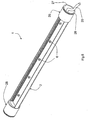
Fig. 2 is a perspective view from behind; -
Figs. 3(a) and (b) are diagrammatic cross-sectional views through the illuminator, showing the configuration of a housing body and how an LED substrate PCB is secured to it; -
Fig. 4 is a perspective view of an end cap for the housing; -
Fig. 5 is a perspective view of the illuminator during manufacture with mounting fixtures attached; -
Figs. 6, 7, and 8 are perspective, end, and side views respectively of a straddle bracket for mounting the illuminator onto conventional shelf supports; -
Figs. 9 and10 are perspective views showing the illuminator being mounted onto the shelf support; -
Fig. 11 is an end view showing an illuminator supported by the brackets; and -
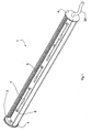
Figs. 12 and 13 are side and front views showing an alternative illuminator and bracket of the invention. - Referring to the drawings an illuminator 1 is of elongate overall configuration, generally similar to that of a conventional illuminator of the fluorescent tube type. The illuminator 1 comprises a
housing body 2 which is a section of a length of extruded aluminium. Atransparent polymer cover 3 is snap-fitted in place across a front opening of thehousing body 2. There is anend cap 4 at each end of thehousing body 2, secured in place by screws into the end faces of thehousing 2. - A
circuit board 5 is supported on thehousing 2, and it is a substrate forLEDs 6 and drive circuits 7. - As shown most clearly in
Figs. 3(a) and 3(b) thehousing body 2 has a supportingplatform 9 for thePCB 5. Achannel 10 runs centrally along the length of thehousing body 2, acting as a guide and receiver forscrews 11 to secure thePCB 5 to thehousing body 2. Thechannel 10 comprises ridges along each side, allowing secure engagement of the screw threads. There is aheat transfer pad 18 between theboard 5 and thehousing platform 9, allowing optimum thermal contact. Alternatively, there may be a different thermally conductive material such as thermally conductive greases or rubber. If there is a pad, it may have an adhesive. - This arrangement presses the
board 5 against thehousing 2 so that there is optimum heat transfer from the underside of theboard 5 into thehousing 2. It also allows the illuminator to be easily assembled during manufacture, and for the PCB to be removed and replaced for any maintenance or upgrade that may be required during its lifetime. Also, there is no need for pre-drilling in thehousing 2 for thescrews 11 as thechannel 10 provides a sufficient guide for engaging screws at any position. - The
housing 2 comprises abase 12 for physical support of theboard 5, for overall strength, and for heat transfer.Heat transfer pads 18 andintegral fins 13 complete a heat transfer path to the surrounding environment. The edges of the fins are rounded to avoid sharp edges. - The
housing body 2 also compriseslongitudinal grooves 14 on each lateral side at the front for retaining thetransparent cover 3. Because the cover is flexible, it can be easily snap-fitted into position. This allows thecover 3 to be easily fitted during manufacture and to be fitted and removed during the lifecycle of the illuminator. In another embodiment, there is less flexibility in the cover. - It will be appreciated from
Figs. 3(a) and 3(b) that the internal surfaces of the housing surrounding thePCB 5 will reflect some light from theLEDs 6, thus optimising the extent of light output and also allowing significant control over the directionality of the light according to the shape of thehousing 2. The shape of the housing may be different from that illustrated in order to achieve a different light output pattern with a different extent of reflection from the internal surfaces. -
Fig. 4 shows anend cap 4 in more detail. It will be noted that there is aledge 15 for additional support of theboard 5, fixingscrew apertures 16, and anaperture 17 forelectrical cable 20 for the board. - It will also be appreciated from the drawings that the illuminator may be manufactured with excellent versatility in terms of its length. One must only cut the extruded
aluminium housing body 2 to the desired section length and cut the plastics cover 3 accordingly. ThePCB 5 is in modular sections with terminals for interconnection. Indeed it is envisaged that the illuminator may even be customised on site to suit the display case into which it is being fitted. - Referring to
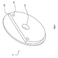
Fig. 5 the illuminator 1 also comprises mountingcouplers 25 secured by grub screws. Eachcoupler 25 is of tubular shape, and at its outer extremity there is acircumferential groove 26 defining anend flange 27. Thecable 20 is trained through thecoupler 25. - The
couplers 25, together withstraddle brackets 30, allow the illuminator to be easily and securely mounted onto conventional shelf supports or brackets B, for retrofitting or original installation. As shown inFigs. 6 to 8 inclusive eachstraddle bracket 30 comprises atop web 31 and two downwardly-dependingflanges 32, forming together an inverted U-shaped configuration. Theflanges 32 have correspondingvertical slots 33 to accommodate thecable 20. Also, there is a pair ofreceivers flange 32, together forming a seat. Each receiver extends at an angle between vertical and horizontal tapered downwardly towards each other. Eachreceiver end flange 27. - Referring to
Figs. 9 ,10 , and11 on one side of astraddle bracket 30 the pair ofreceivers 35 together form a seat to receive theflange 27 of acoupler 25. Because of the angles at which thereceivers straddle bracket 30. - It will also be appreciated that the sleeve-shaped
couplers 25 and thestraddle brackets 30 allow the illuminator to be easily and quickly mounted in a display cabinet having conventional shelf supports or brackets B, allowing very easy retrofitting. What has been achieved is excellent illuminator support stability, versatility for rotation to a desired illumination direction, and very simple fitting/installation either retrofitted or original.Fig. 11 in particular shows how thetop web 31 of thebracket 30 is matched in height by afixture 40 over the shelf support B to ensure horizontal mounting of the shelf S. - The illuminator, when installed, can be rotated to any desired orientation so that it may for example illuminate items on a shelf underneath it. Alternatively, it may be upwardly directed to illuminate items above it through a glass shelf supported on the shelf support brackets.
- Another advantage of the illuminator is that the manufacturer can easily choose illumination parameters by simply choosing the desired configuration of
modular boards 5. For example, there may be a specific chosen pattern of different LEDs to achieve a particular illumination effect. Another versatile parameter is the length of thehousing body 2, and hence of the illuminator. - It will be appreciated that the illuminator has a similar physical configuration to a conventional fluorescent illuminator, allowing the latter to be replaced with illuminators which do not give rise to hazardous waste disposal issues. Indeed, it is envisaged that, in another embodiment, the illuminator may be configured to fit into a support and power supply of a conventional fluorescent illuminator. Thus the illuminator may be supplied as a plug-in replacement for a fluorescent tube, with the fluorescent tube electrical supply providing power to the circuit. The power supply may be mains or down-converted AC or DC depending upon the illumination requirements. This embodiment may include a safety feature for by-passing or disconnecting a ballast to ensure that high voltages are not applied.
- In use; it is preferable that a pair of
opposed straddle brackets 30 supports an illuminator, however with suitable configuration of the brackets and couplers (and possible size and weight of housing) a single straddle bracket may provide cantilevered support. This allows further versatility. - It is also envisaged that the illuminator may form part of a frame of a display case, such as a mullion.
- Referring to
Figs. 12 and 13 in another embodiment abracket 50 has a U-shapedshelf edge surround 51 for straddling the front edge of a shelf S and ascrew 52 to secure thebracket 51 in place. The lower flange of thesurround 51 is secured to a depending andcircular illuminator support 53 through which theilluminator coupler 25 fits. Again, this allows the illuminator to be easily retro-fitted to an existing cabinet, and to be rotated to an optimum illumination position. - In a further embodiment, an illuminator support may have a bracket similar to the
bracket 50, but the support means may be similar to the arrangement in thebracket 30, with opposed cut-outs or grooves forming a seat for the ends of the illuminator. - The invention is not limited to the embodiments described but may be varied in construction and detail, within the scope of the appended claims.
Claims (17)
- An illuminator assembly comprising an illuminator (1) having a housing (2, 3, 25) and at least one light emitting diode (6) mounted on a substrate (5) within the housing, and an illuminator support (25, 30) for mounting the illuminator in a goods cabinet,
wherein the illuminator (1) is of elongate shape, and
wherein the illuminator support (25, 30) comprises at least one bracket (30) for fitting to a planar goods cabinet shelf or shelf support (S), the bracket being configured to straddle the shelf or shelf support at an edge thereof and including a support means (34, 35) to engage the housing to support the illuminator; and
wherein the housing comprises a platform (9) for the substrate (5), characterised in that the housing comprises at least one receiver for fasteners (11) securing the substrate on the platform (9), the fastener receiver comprising a channel extending along the length of the housing. - An illuminator assembly as claimed in claim 1, wherein the housing comprises a housing body (2) of elongate material, and end caps (4) secured to the ends of the housing body.
- An illuminator assembly as claimed in either of claims 1 or 2, wherein the channel comprises side ridges along its length for engagement with screw fastener threads.
- An illuminator assembly as claimed in any preceding claim, wherein the housing comprises a base (10) of thermally-conductive material under the substrate to provide a heat transfer path for heat from the substrate; and
wherein the illuminator further comprises a heat transfer material (18) between the substrate and the platform (9). - An illuminator assembly as claimed in any preceding claim, wherein the housing comprises heat transfer fins (13) which are substantially parallel and fit within an overall curved outer periphery configuration.
- An illuminator assembly as claimed in any preceding claim, wherein the cross-sectional shape of the housing is substantially circular.
- An illuminator assembly as claimed in any preceding claim, further comprising a cover (3) over the diodes (6); and wherein the cover (3) is of flexible material, retained in its shape by engaging the housing on opposed sides.
- An illuminator assembly as claimed in claim 7, wherein the housing comprises a pair of opposed grooves (14) to receive and retain opposed side edges of the cover; and wherein the grooves (14) are configured to allow manual removal and re-insertion of the cover.
- An illuminator assembly as claimed in either of claims 7 to 8, wherein the cover (3) is of transparent plastics or polymer material.
- An illuminator assembly as claimed in any preceding claim, wherein the substrate comprises modular substrate parts with end terminals for interconnection.
- An illuminator assembly as claimed in any preceding claim, wherein the bracket (30, 51) is of U-shaped configuration, having a pair of opposed flanges interconnected by a web, said flanges being configured for gripping a planar shelf or shelf support on opposed surfaces.
- An illuminator assembly as claimed in claim 11, wherein the support means allows the housing to be rotated.
- An illuminator assembly as claimed in claim 12, wherein the support means comprises a seat (34, 35) for an end of the illuminator; and wherein the seat comprises a pair of opposed receivers (34, 35), and the illuminator comprises a flange 27) for engaging in the receivers.
- An illuminator assembly as claimed in claim 13, wherein the receivers are inclined downwardly and inwardly towards each other.
- An illuminator assembly as claimed in claim 12, wherein the support means comprises an annular support (53) configured to receive an end of the housing.
- An illuminator assembly as claimed in any preceding claim, wherein the illuminator comprises a flange (27) on a sleeve-shaped coupler (25) secured to a housing main body (2), said flange being for engagement with the support means; and wherein there is a circumferential groove (26) behind the flange, and the support means engages in the groove.
- A method of manufacturing an illuminator as claimed in any of claims 7 to 16, the method comprising the steps of:cutting a length of extruded housing body extrusion material to provide the housing body (2) with a desired length,cutting a length of cover material to provide the cover (3) with a desired length,providing at least two modular light emitting diode substrates, and interconnecting them on the platform (9) of the housing body,snap-fitting the cover (3) in place between the opposed grooves (14),securing the end caps (4) to the ends of the housing body; andwherein the housing body has a channel running along the length of the platform (9), and the substrate is secured in place by fastening screws at appropriate locations along the channel.
Applications Claiming Priority (2)
| Application Number | Priority Date | Filing Date | Title |
|---|---|---|---|
| US72619605P | 2005-10-14 | 2005-10-14 | |
| PCT/IE2006/000113 WO2007043034A2 (en) | 2005-10-14 | 2006-10-16 | An illuminator |
Publications (2)
| Publication Number | Publication Date |
|---|---|
| EP1934518A2 EP1934518A2 (en) | 2008-06-25 |
| EP1934518B1 true EP1934518B1 (en) | 2009-09-16 |
Family
ID=37420922
Family Applications (1)
| Application Number | Title | Priority Date | Filing Date |
|---|---|---|---|
| EP06796055A Not-in-force EP1934518B1 (en) | 2005-10-14 | 2006-10-16 | An illuminator |
Country Status (5)
| Country | Link |
|---|---|
| EP (1) | EP1934518B1 (en) |
| AT (1) | ATE443234T1 (en) |
| DE (1) | DE602006009283D1 (en) |
| IE (1) | IE84817B1 (en) |
| WO (1) | WO2007043034A2 (en) |
Cited By (1)
| Publication number | Priority date | Publication date | Assignee | Title |
|---|---|---|---|---|
| WO2021154726A1 (en) * | 2020-01-27 | 2021-08-05 | Elemental LED, Inc. | Flexible cover for linear lighting channels |
Families Citing this family (14)
| Publication number | Priority date | Publication date | Assignee | Title |
|---|---|---|---|---|
| JP5124176B2 (en) | 2007-06-11 | 2013-01-23 | 三洋電機株式会社 | Showcase |
| TW200905131A (en) * | 2007-07-27 | 2009-02-01 | Ledtech Electronics Corp | Lamp assembly |
| JP5311798B2 (en) | 2007-11-01 | 2013-10-09 | 三洋電機株式会社 | Showcase |
| WO2009079209A1 (en) * | 2007-12-17 | 2009-06-25 | Illinois Tool Works Inc. | Inductively powered light assembly |
| TWM345942U (en) * | 2008-05-16 | 2008-12-01 | Ledtech Electronics Corp | Customized assembling lighting module |
| EP2151621A1 (en) * | 2008-08-05 | 2010-02-10 | Augux Co., Ltd. | Light emitting diode lighting set |
| JP5389396B2 (en) * | 2008-08-18 | 2014-01-15 | 三洋電機株式会社 | Showcase |
| NL2003481C2 (en) * | 2008-10-24 | 2010-11-23 | Ec Vastgoed B V | Improved led arrangement and lamp assemblies. |
| KR100913925B1 (en) * | 2008-10-27 | 2009-08-27 | 화우테크놀러지 주식회사 | Fluorescent lamp type led lamp with adjustable lighting direction |
| ES2361879B1 (en) * | 2008-11-20 | 2012-06-22 | Lidolight Saving Energy, S.L. | LUMINARY. |
| NL1036294C2 (en) * | 2008-12-08 | 2011-08-30 | Nicolaas Veldboer | LED LAMP WITH COOLING EQUIPMENT. |
| JP5312068B2 (en) * | 2009-01-30 | 2013-10-09 | 三洋電機株式会社 | Showcase |
| US9516954B2 (en) * | 2013-09-11 | 2016-12-13 | GE Lighting Solutions, LLC | Showcase member with direct-mounted LED light source |
| PL232922B1 (en) * | 2017-09-12 | 2019-08-30 | Zamel Spolka Z Ograniczona Odpowiedzialnoscia | Method for connecting frames of lightning fittings |
Family Cites Families (4)
| Publication number | Priority date | Publication date | Assignee | Title |
|---|---|---|---|---|
| US6283612B1 (en) * | 2000-03-13 | 2001-09-04 | Mark A. Hunter | Light emitting diode light strip |
| FR2819577B1 (en) * | 2001-01-12 | 2003-07-18 | Herger | LED ILLUMINATED SHELF |
| US7121675B2 (en) * | 2002-01-10 | 2006-10-17 | Artak Ter-Hovhannisian | Low temperature LED lighting system |
| US7513637B2 (en) * | 2004-12-23 | 2009-04-07 | Nualight Limited | Display cabinet illumination |
-
2006
- 2006-10-16 AT AT06796055T patent/ATE443234T1/en not_active IP Right Cessation
- 2006-10-16 EP EP06796055A patent/EP1934518B1/en not_active Not-in-force
- 2006-10-16 WO PCT/IE2006/000113 patent/WO2007043034A2/en active Application Filing
- 2006-10-16 IE IE20060761A patent/IE84817B1/en not_active IP Right Cessation
- 2006-10-16 DE DE602006009283T patent/DE602006009283D1/en active Active
Cited By (3)
| Publication number | Priority date | Publication date | Assignee | Title |
|---|---|---|---|---|
| WO2021154726A1 (en) * | 2020-01-27 | 2021-08-05 | Elemental LED, Inc. | Flexible cover for linear lighting channels |
| US11118752B2 (en) | 2020-01-27 | 2021-09-14 | Elemental LED, Inc. | Flexible cover for linear lighting channels |
| US11125411B1 (en) | 2020-01-27 | 2021-09-21 | Elemental LED, Inc. | Flexible cover for linear lighting channels |
Also Published As
| Publication number | Publication date |
|---|---|
| EP1934518A2 (en) | 2008-06-25 |
| WO2007043034A8 (en) | 2009-02-05 |
| WO2007043034A2 (en) | 2007-04-19 |
| IE20060761A1 (en) | 2007-06-13 |
| WO2007043034A3 (en) | 2007-06-07 |
| DE602006009283D1 (en) | 2009-10-29 |
| ATE443234T1 (en) | 2009-10-15 |
| IE84817B1 (en) | 2008-02-06 |
Similar Documents
| Publication | Publication Date | Title |
|---|---|---|
| EP1934518B1 (en) | An illuminator | |
| AU2012238294B2 (en) | Edge-lit luminaire | |
| US6299327B1 (en) | Light fixture with multi-purpose mounting arrangement | |
| EP2444716B1 (en) | Lighting apparatus | |
| US8287160B2 (en) | LED light assembly | |
| US8960962B2 (en) | Ceiling mount fixture | |
| JP2007165051A (en) | Led lighting lamp | |
| KR101731680B1 (en) | Ceiling light Mounting and Separating Device | |
| JP2011014317A (en) | Lighting body and lighting system | |
| CA3101908C (en) | Lighting system | |
| KR101859881B1 (en) | Mounting apparatus for LED lighting | |
| WO2021116068A1 (en) | Universal mount adapter for light fixtures | |
| US9121569B2 (en) | Lighting apparatus having a housing to accomodate a removable diffuser | |
| KR200483716Y1 (en) | Apparatus for mounting an led module to a lighting apparatus | |
| KR200470352Y1 (en) | LED Lighting | |
| KR102267048B1 (en) | Mounting Housing for Lighting Installation | |
| KR102257471B1 (en) | Assembly converter for flat edge lighting | |
| JP5399550B2 (en) | Display shelf lighting equipment | |
| US20200182437A1 (en) | Luminaire with Improved Assembly, Installation, and Wireless Functionality | |
| GB2574138A (en) | High bay Luminaire | |
| US10634293B1 (en) | Retrofit light fixture | |
| KR100781903B1 (en) | Lighting apparatus using led module | |
| KR200356235Y1 (en) | easily installable fluorescent lamps | |
| EP2957826B1 (en) | Lighting panel assembly | |
| KR20190004432A (en) | LED lamp with adjust installation positio |
Legal Events
| Date | Code | Title | Description |
|---|---|---|---|
| PUAI | Public reference made under article 153(3) epc to a published international application that has entered the european phase |
Free format text: ORIGINAL CODE: 0009012 |
|
| 17P | Request for examination filed |
Effective date: 20080416 |
|
| AK | Designated contracting states |
Kind code of ref document: A2 Designated state(s): AT BE BG CH CY CZ DE DK EE ES FI FR GB GR HU IE IS IT LI LT LU LV MC NL PL PT RO SE SI SK TR |
|
| GRAP | Despatch of communication of intention to grant a patent |
Free format text: ORIGINAL CODE: EPIDOSNIGR1 |
|
| DAX | Request for extension of the european patent (deleted) | ||
| RAP1 | Party data changed (applicant data changed or rights of an application transferred) |
Owner name: NUALIGHT LIMITED |
|
| GRAS | Grant fee paid |
Free format text: ORIGINAL CODE: EPIDOSNIGR3 |
|
| GRAA | (expected) grant |
Free format text: ORIGINAL CODE: 0009210 |
|
| AK | Designated contracting states |
Kind code of ref document: B1 Designated state(s): AT BE BG CH CY CZ DE DK EE ES FI FR GB GR HU IS IT LI LT LU LV MC NL PL PT RO SE SI SK TR |
|
| REG | Reference to a national code |
Ref country code: GB Ref legal event code: FG4D |
|
| REG | Reference to a national code |
Ref country code: CH Ref legal event code: EP |
|
| REF | Corresponds to: |
Ref document number: 602006009283 Country of ref document: DE Date of ref document: 20091029 Kind code of ref document: P |
|
| PG25 | Lapsed in a contracting state [announced via postgrant information from national office to epo] |
Ref country code: SE Free format text: LAPSE BECAUSE OF FAILURE TO SUBMIT A TRANSLATION OF THE DESCRIPTION OR TO PAY THE FEE WITHIN THE PRESCRIBED TIME-LIMIT Effective date: 20090916 Ref country code: FI Free format text: LAPSE BECAUSE OF FAILURE TO SUBMIT A TRANSLATION OF THE DESCRIPTION OR TO PAY THE FEE WITHIN THE PRESCRIBED TIME-LIMIT Effective date: 20090916 Ref country code: LT Free format text: LAPSE BECAUSE OF FAILURE TO SUBMIT A TRANSLATION OF THE DESCRIPTION OR TO PAY THE FEE WITHIN THE PRESCRIBED TIME-LIMIT Effective date: 20090916 |
|
| LTIE | Lt: invalidation of european patent or patent extension |
Effective date: 20090916 |
|
| PG25 | Lapsed in a contracting state [announced via postgrant information from national office to epo] |
Ref country code: LV Free format text: LAPSE BECAUSE OF FAILURE TO SUBMIT A TRANSLATION OF THE DESCRIPTION OR TO PAY THE FEE WITHIN THE PRESCRIBED TIME-LIMIT Effective date: 20090916 Ref country code: PL Free format text: LAPSE BECAUSE OF FAILURE TO SUBMIT A TRANSLATION OF THE DESCRIPTION OR TO PAY THE FEE WITHIN THE PRESCRIBED TIME-LIMIT Effective date: 20090916 Ref country code: SI Free format text: LAPSE BECAUSE OF FAILURE TO SUBMIT A TRANSLATION OF THE DESCRIPTION OR TO PAY THE FEE WITHIN THE PRESCRIBED TIME-LIMIT Effective date: 20090916 Ref country code: NL Free format text: LAPSE BECAUSE OF FAILURE TO SUBMIT A TRANSLATION OF THE DESCRIPTION OR TO PAY THE FEE WITHIN THE PRESCRIBED TIME-LIMIT Effective date: 20090916 |
|
| NLV1 | Nl: lapsed or annulled due to failure to fulfill the requirements of art. 29p and 29m of the patents act | ||
| PG25 | Lapsed in a contracting state [announced via postgrant information from national office to epo] |
Ref country code: CY Free format text: LAPSE BECAUSE OF FAILURE TO SUBMIT A TRANSLATION OF THE DESCRIPTION OR TO PAY THE FEE WITHIN THE PRESCRIBED TIME-LIMIT Effective date: 20090916 |
|
| PG25 | Lapsed in a contracting state [announced via postgrant information from national office to epo] |
Ref country code: CZ Free format text: LAPSE BECAUSE OF FAILURE TO SUBMIT A TRANSLATION OF THE DESCRIPTION OR TO PAY THE FEE WITHIN THE PRESCRIBED TIME-LIMIT Effective date: 20090916 Ref country code: RO Free format text: LAPSE BECAUSE OF FAILURE TO SUBMIT A TRANSLATION OF THE DESCRIPTION OR TO PAY THE FEE WITHIN THE PRESCRIBED TIME-LIMIT Effective date: 20090916 Ref country code: PT Free format text: LAPSE BECAUSE OF FAILURE TO SUBMIT A TRANSLATION OF THE DESCRIPTION OR TO PAY THE FEE WITHIN THE PRESCRIBED TIME-LIMIT Effective date: 20100118 Ref country code: IS Free format text: LAPSE BECAUSE OF FAILURE TO SUBMIT A TRANSLATION OF THE DESCRIPTION OR TO PAY THE FEE WITHIN THE PRESCRIBED TIME-LIMIT Effective date: 20100116 Ref country code: ES Free format text: LAPSE BECAUSE OF FAILURE TO SUBMIT A TRANSLATION OF THE DESCRIPTION OR TO PAY THE FEE WITHIN THE PRESCRIBED TIME-LIMIT Effective date: 20091227 Ref country code: EE Free format text: LAPSE BECAUSE OF FAILURE TO SUBMIT A TRANSLATION OF THE DESCRIPTION OR TO PAY THE FEE WITHIN THE PRESCRIBED TIME-LIMIT Effective date: 20090916 |
|
| PG25 | Lapsed in a contracting state [announced via postgrant information from national office to epo] |
Ref country code: MC Free format text: LAPSE BECAUSE OF NON-PAYMENT OF DUE FEES Effective date: 20091031 Ref country code: SK Free format text: LAPSE BECAUSE OF FAILURE TO SUBMIT A TRANSLATION OF THE DESCRIPTION OR TO PAY THE FEE WITHIN THE PRESCRIBED TIME-LIMIT Effective date: 20090916 |
|
| PG25 | Lapsed in a contracting state [announced via postgrant information from national office to epo] |
Ref country code: BE Free format text: LAPSE BECAUSE OF FAILURE TO SUBMIT A TRANSLATION OF THE DESCRIPTION OR TO PAY THE FEE WITHIN THE PRESCRIBED TIME-LIMIT Effective date: 20090916 Ref country code: AT Free format text: LAPSE BECAUSE OF FAILURE TO SUBMIT A TRANSLATION OF THE DESCRIPTION OR TO PAY THE FEE WITHIN THE PRESCRIBED TIME-LIMIT Effective date: 20090916 |
|
| PLBE | No opposition filed within time limit |
Free format text: ORIGINAL CODE: 0009261 |
|
| REG | Reference to a national code |
Ref country code: FR Ref legal event code: ST Effective date: 20100630 |
|
| STAA | Information on the status of an ep patent application or granted ep patent |
Free format text: STATUS: NO OPPOSITION FILED WITHIN TIME LIMIT |
|
| PG25 | Lapsed in a contracting state [announced via postgrant information from national office to epo] |
Ref country code: FR Free format text: LAPSE BECAUSE OF NON-PAYMENT OF DUE FEES Effective date: 20091116 Ref country code: DK Free format text: LAPSE BECAUSE OF FAILURE TO SUBMIT A TRANSLATION OF THE DESCRIPTION OR TO PAY THE FEE WITHIN THE PRESCRIBED TIME-LIMIT Effective date: 20090916 |
|
| 26N | No opposition filed |
Effective date: 20100617 |
|
| PG25 | Lapsed in a contracting state [announced via postgrant information from national office to epo] |
Ref country code: GR Free format text: LAPSE BECAUSE OF FAILURE TO SUBMIT A TRANSLATION OF THE DESCRIPTION OR TO PAY THE FEE WITHIN THE PRESCRIBED TIME-LIMIT Effective date: 20091217 |
|
| PG25 | Lapsed in a contracting state [announced via postgrant information from national office to epo] |
Ref country code: BG Free format text: LAPSE BECAUSE OF FAILURE TO SUBMIT A TRANSLATION OF THE DESCRIPTION OR TO PAY THE FEE WITHIN THE PRESCRIBED TIME-LIMIT Effective date: 20091031 Ref country code: IT Free format text: LAPSE BECAUSE OF FAILURE TO SUBMIT A TRANSLATION OF THE DESCRIPTION OR TO PAY THE FEE WITHIN THE PRESCRIBED TIME-LIMIT Effective date: 20090916 |
|
| PG25 | Lapsed in a contracting state [announced via postgrant information from national office to epo] |
Ref country code: LU Free format text: LAPSE BECAUSE OF NON-PAYMENT OF DUE FEES Effective date: 20091016 |
|
| REG | Reference to a national code |
Ref country code: CH Ref legal event code: PL |
|
| PG25 | Lapsed in a contracting state [announced via postgrant information from national office to epo] |
Ref country code: HU Free format text: LAPSE BECAUSE OF FAILURE TO SUBMIT A TRANSLATION OF THE DESCRIPTION OR TO PAY THE FEE WITHIN THE PRESCRIBED TIME-LIMIT Effective date: 20100317 |
|
| PG25 | Lapsed in a contracting state [announced via postgrant information from national office to epo] |
Ref country code: LI Free format text: LAPSE BECAUSE OF NON-PAYMENT OF DUE FEES Effective date: 20101031 Ref country code: CH Free format text: LAPSE BECAUSE OF NON-PAYMENT OF DUE FEES Effective date: 20101031 |
|
| PG25 | Lapsed in a contracting state [announced via postgrant information from national office to epo] |
Ref country code: TR Free format text: LAPSE BECAUSE OF FAILURE TO SUBMIT A TRANSLATION OF THE DESCRIPTION OR TO PAY THE FEE WITHIN THE PRESCRIBED TIME-LIMIT Effective date: 20090916 |
|
| PGFP | Annual fee paid to national office [announced via postgrant information from national office to epo] |
Ref country code: GB Payment date: 20120806 Year of fee payment: 7 |
|
| PGFP | Annual fee paid to national office [announced via postgrant information from national office to epo] |
Ref country code: DE Payment date: 20120913 Year of fee payment: 7 |
|
| GBPC | Gb: european patent ceased through non-payment of renewal fee |
Effective date: 20131016 |
|
| PG25 | Lapsed in a contracting state [announced via postgrant information from national office to epo] |
Ref country code: GB Free format text: LAPSE BECAUSE OF NON-PAYMENT OF DUE FEES Effective date: 20131016 |
|
| REG | Reference to a national code |
Ref country code: DE Ref legal event code: R119 Ref document number: 602006009283 Country of ref document: DE Effective date: 20140501 |
|
| PG25 | Lapsed in a contracting state [announced via postgrant information from national office to epo] |
Ref country code: DE Free format text: LAPSE BECAUSE OF NON-PAYMENT OF DUE FEES Effective date: 20140501 |