EP1933477A1 - A optical fiber access network and a communication protection method thereof - Google Patents
A optical fiber access network and a communication protection method thereof Download PDFInfo
- Publication number
- EP1933477A1 EP1933477A1 EP06775490A EP06775490A EP1933477A1 EP 1933477 A1 EP1933477 A1 EP 1933477A1 EP 06775490 A EP06775490 A EP 06775490A EP 06775490 A EP06775490 A EP 06775490A EP 1933477 A1 EP1933477 A1 EP 1933477A1
- Authority
- EP
- European Patent Office
- Prior art keywords
- optical
- optical fiber
- communication service
- user terminal
- wireless
- Prior art date
- Legal status (The legal status is an assumption and is not a legal conclusion. Google has not performed a legal analysis and makes no representation as to the accuracy of the status listed.)
- Granted
Links
- 238000004891 communication Methods 0.000 title claims abstract description 164
- 239000013307 optical fiber Substances 0.000 title claims abstract description 120
- 238000000034 method Methods 0.000 title claims abstract description 11
- 230000003287 optical effect Effects 0.000 claims abstract description 123
- 238000001514 detection method Methods 0.000 claims description 27
- 230000010354 integration Effects 0.000 claims description 10
- 238000012790 confirmation Methods 0.000 claims description 4
- 239000000835 fiber Substances 0.000 description 5
- 238000012423 maintenance Methods 0.000 description 5
- 238000012545 processing Methods 0.000 description 4
- 230000005540 biological transmission Effects 0.000 description 3
- 238000010276 construction Methods 0.000 description 2
- 230000008878 coupling Effects 0.000 description 1
- 238000010168 coupling process Methods 0.000 description 1
- 238000005859 coupling reaction Methods 0.000 description 1
- 230000007547 defect Effects 0.000 description 1
- 230000002950 deficient Effects 0.000 description 1
- 238000012986 modification Methods 0.000 description 1
- 230000004048 modification Effects 0.000 description 1
Images


Classifications
-
- H—ELECTRICITY
- H04—ELECTRIC COMMUNICATION TECHNIQUE
- H04B—TRANSMISSION
- H04B10/00—Transmission systems employing electromagnetic waves other than radio-waves, e.g. infrared, visible or ultraviolet light, or employing corpuscular radiation, e.g. quantum communication
- H04B10/25—Arrangements specific to fibre transmission
-
- H—ELECTRICITY
- H04—ELECTRIC COMMUNICATION TECHNIQUE
- H04B—TRANSMISSION
- H04B10/00—Transmission systems employing electromagnetic waves other than radio-waves, e.g. infrared, visible or ultraviolet light, or employing corpuscular radiation, e.g. quantum communication
- H04B10/03—Arrangements for fault recovery
- H04B10/032—Arrangements for fault recovery using working and protection systems
-
- H—ELECTRICITY
- H04—ELECTRIC COMMUNICATION TECHNIQUE
- H04B—TRANSMISSION
- H04B10/00—Transmission systems employing electromagnetic waves other than radio-waves, e.g. infrared, visible or ultraviolet light, or employing corpuscular radiation, e.g. quantum communication
-
- H—ELECTRICITY
- H04—ELECTRIC COMMUNICATION TECHNIQUE
- H04J—MULTIPLEX COMMUNICATION
- H04J3/00—Time-division multiplex systems
- H04J3/02—Details
- H04J3/14—Monitoring arrangements
-
- H—ELECTRICITY
- H04—ELECTRIC COMMUNICATION TECHNIQUE
- H04J—MULTIPLEX COMMUNICATION
- H04J3/00—Time-division multiplex systems
- H04J3/16—Time-division multiplex systems in which the time allocation to individual channels within a transmission cycle is variable, e.g. to accommodate varying complexity of signals, to vary number of channels transmitted
- H04J3/1694—Allocation of channels in TDM/TDMA networks, e.g. distributed multiplexers
-
- H—ELECTRICITY
- H04—ELECTRIC COMMUNICATION TECHNIQUE
- H04W—WIRELESS COMMUNICATION NETWORKS
- H04W24/00—Supervisory, monitoring or testing arrangements
- H04W24/04—Arrangements for maintaining operational condition
-
- H—ELECTRICITY
- H04—ELECTRIC COMMUNICATION TECHNIQUE
- H04W—WIRELESS COMMUNICATION NETWORKS
- H04W88/00—Devices specially adapted for wireless communication networks, e.g. terminals, base stations or access point devices
- H04W88/08—Access point devices
Definitions
- the present invention relates to an optical fiber access network and communication protection method thereof and especially relates to an optical fiber access network which can provide the function of communication protection and provide wireless communication protection when the optical fiber breaks, and a communication protection method which can protect the communication service from influence.
- the optical fiber access network is the inevitable trend of optical fiber communication.
- the optical fiber access network normally has five sorts of topological structures as follows: single star topology, multi-star topology, tree topology, bus topology and ring topology.
- the former four sorts can be called star structure.
- the star network can save more optical fibers and optical receiving and sending modules, and the branch structure of it is easy for coverage. Therefore, the star structure is normally adopted in the optical fiber access network.
- the optical fiber line For protecting the normal work of communication service, the optical fiber line needs to be protected in the optical fiber access network.
- the protection manner of the optical fiber line between the optical line terminal and the optical network unit is as follows:
- the main subject of the present invention is to provide an optical fiber access network and a communication protection method thereof aiming at the above-mentioned defect existed in the 1+1 protection manner of the optical fiber access network and the reason and current situation that the protection to the optical fiber line between the optical branching divider and the optical network unit in the star topology optical fiber access network is deficient in practical use.
- the optical fiber access network and the method assemble the wireless communication system and optical fiber communication system so as to make the communication service of the optical fiber communication system obtain powerful insurance and effectively use the communication resource.
- the present invention adopts an optical fiber access network which comprises an optical fiber communication system which at least consists of an optical line terminal 1, an optical branching divider 2, a first optical network unit 3 and an user terminal integration access device 4.
- a work optical fiber 91 and a protection optical fiber 92 for protecting the line of said work optical fiber 91 are set between the optical line terminal 1 and the optical branching divider 2.
- Said optical fiber access network also comprises a wireless base station 5 which is connected with said optical branching divider 2 through a second optical network unit 6.
- Said wireless base station 5 wirelessly communicates with a wireless user terminal device 7.
- the wireless user terminal device 7 and said first optical network unit 3 are connected with a communication service switch device 8 for switching the communication line respectively.
- the communication service switch device 8 is connected with said user terminal integration access device 4.
- Said wireless user terminal device 7 further communicates with said first optical network unit 3.
- Said optical line terminal 1 is provided with a first detection module 11 for detecting the signal in the work optical fiber 91 and the protection optical fiber 92, and a network managing system 12 for managing the integrated services of said optical line terminal 1.
- Said first detection module 11 is connected with said network management system 12.
- Said first optical network unit 3 is provided with a second detection module 31 for detecting signals and a control module 32 for sending a switching control signal to said communication service switch device 8. Wherein, said second detection module 31 can be connected with said control module 32.
- Said communication service switch device 8 can be set in said the first optical network unit 3, that is to say said communication service switch device 8 can be put into said first optical network unit 3, i.e. said communication service switch device 8 is integrated with said first optical network unit 3.
- the optical fiber access network can provide protection in wireless manner for the communication service between the optical branching divider and the optical network unit.
- the second detection module 31 detects the amplitude, power and/or energy of the signal transmitting in the optical fiber communication system.
- the second detection module 31 detects that the amplitude, power and/or energy of the signal are lower than the preset threshold and considers that the signal is lost.
- the communication service switch device 8 switches the user terminal integration access device 4 to the wireless user terminal device 7 to make the communication service of the optical fiber communication system be switched to the wireless communication system.
- optical fiber communication is better than the wireless communication system in the aspect of transmitting rate and stability and so on, it is considered that the failure of being cut in the optical fiber is eliminated when the second detection module 31 detects that the amplitude, power and/or energy of the signal from branching divider 2 are higher than the preset threshold.
- the communication service switch device 8 switches the user terminal integration access device 4 to the first optical network unit 3 make the communication service be switched back to the optical fiber communication system.
- the present invention adopts the 1+1 protection manner to protect the optical fiber line between the optical line terminal and the optical branching divider in the optical fiber access network, and adopts the wireless communication system to protect the optical fiber line between the optical branching divider and the optical network unit in the star structure optical fiber access network at the same time, which not only meets the need of user to the unusable time of the network so as to ensure the fluency of the communication service of the user in the stat structure optical network and especially the group users, but also breaks through the restriction of the resource of the pipe and optical cable and reduces the cost of investment, operation and maintenance. It can also be used to quickly cover the communication area where there is no optical cable in wireless way.
- the wireless communication system can be used as the protection system of the optical fiber communication system so as to facilitate the implementation step by step and the utilization of the device.
- the present invention sets the wireless base station near the optical branching divider so as to reduce the requirement for the coverage scope of the wireless base station.
- the present invention adopts the wireless communication system which can dynamically allocate the bandwidth to protect the fiber access network. After the failure of being cut off in the access optical fiber happens, the bandwidth of the wireless communication system can be concentrated to the optical network unit influenced to protect the bandwidth need of the user. When there isn't any failure, it can provide the wireless access service for many users so as to increase the utilization rate of the bandwidth in the communication system and enrich the service provided.
- the main idea of the present invention is to bring in the wireless communication system to protect the optical fiber line between the optical branching divider 2 and the first optical network unit 3 in the star structure optical fiber access network.
- the optical fiber access network with protection comprises the optical fiber communication system, the wireless communication system, the second optical network unit 6, and the communication service switch device 8.
- the communication service switch device 8 switches the communication service from the optical fiber communication system to the wireless communication system when there is failure of being cut off in the optical fiber between the optical branching divider 2 and the first optical network unit 3 in the optical fiber communication system. Because the optical fiber communication is better than the wireless communication system at the aspect of transmitting rate and stability, etc, the communication service switch device 8 switches the communication service from the wireless communication system back to the optical fiber communication system after the failure of being cut off in the optical fiber is cleared.
- Fig. 1 is the system structure view of the optical fiber access network in accordance with the present invention.
- the optical fiber communication system at least comprises an optical line terminal 1, an optical branching divider 2, the first optical network unit 3 and an integration access device of user terminal 4.
- the optical line terminal 1 has an interface to the switching equipment, router and the optical branching divider 2 to communicate with the optical branching divider through the work fiber 91 and the protection optical fiber 92 which protects the line of the work fiber 91, and provide necessary means to transmit various communication services.
- a first detection module 11 for detecting the signal in the work fiber 91 and protection optical fiber 92 and a network managing system 12 for managing integrated services of the optical line terminal 1 are set in the optical line terminal 1.
- the first detection module 11 is connected with the network managing system12.
- the optical branching divider 2 provides the physical connection taking optical fiber as the transmission medium for the first optical network unit 3 and optical line terminal 1, makes the signal transmitted in optical fiber conduct power reallocation after being coupled in the coupling area.
- the first optical network unit 3 is connected with the communication service switch device 8 for switching the communication line by optical fibers.
- the first optical network unit 3 at least comprises a second detection module 31 for detecting signals, an alarm module 33 for producing an alarm message of signal loss when the second detection module 31 detects no signal, a control module 32 for sending a switch control signal to the communication service switch device 8, a service interface function module 34 for sending and receiving the message of the wireless user terminal device 7 and a power supply and maintenance management function module 35 for supplying power and managing integrated services to the first optical network unit 3.
- the second detection module 31 is connected with the alarm module and the power supply and maintenance management function module, and can also be connected with the control module 32. Specifically, amplitude, power and/or energy detection devices and so on can be adopted.
- the alarm module 33 is connected with the service interface function module 34 and can be integrated with the detection module 31.
- the service interface function module 34 is also connected with the power supply and maintenance management function module 35 and the communication service switch device 8, and is connected with the optical branching divider 2 and the wireless user terminal device 7.
- the control module 32 is communicated with the service interface function module 34 and the power supply and maintenance management function module 35.
- the wireless communication system comprises a wireless base station 5 and the wireless user terminal device 7, wherein the wireless base station 5 is set near the optical branching divider 2, communicates with the optical branching divider 2 through the second optical network unit 6, and wirelessly communicates with the wireless user terminal device 7 so as to accomplishing the wireless sending and receiving and the management of the wireless resource etc, which can be a point to point system or one point to several points system, for example, a WiMax system.
- the wireless user terminal device 7 is provided with a first optical network unit 3 and the interface of the user terminal integration access device 4.
- the wireless user terminal device 7 is connected with the communication service switch device 8 for switching the communication line, and is connected with said first optical network unit 3 for receiving the alarm message coming from the first optical network unit 3 and the communication service switched so as to realize the message transmission between the wireless base station 5 and the user terminal integration access device 4.
- Communication service switch device 8 is used to switch the communication line, wherein the wireless user terminal device 7 and the first optical network unit 3 are connected with the communication service switch device 8 respectively.
- the communication service switch device 8 is connected with the user terminal integration access device 4.
- the switch of the communication service switch device 8 is controlled by the control module 32 in the first optical network unit 3, which can be set independent to the first optical network unit 3 or in the first optical network unit 3, i.e. integrated with the communication service switch device 8.
- an electric switch, an optical switch, a photoelectric switch, a micro-mechanical switch or an optical waveguide switch and so on can be adopted.
- the second detection module 31 detects the signal transmitted in the work line.
- the communication service switch device 8 switches the communication service transmitted between the optical wiring network 2 and the first optical network unit 3 to the wireless communication system, i.e. switches the communication service from the optical fiber communication system to the wireless communication system.
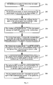
- Fig. 2 it is the specific processing flow of switching the communication service from the optical fiber communication system to the wireless communication system, and following steps are executed:
- the message of signal loss can also be directly sent to the control module 32 after the second power meter 31 detects that the downlink signal power is less than the preset threshold power.
- the control module 32 controls the switch to switch the communication service to the wireless communication system, i.e. the steps 202 ⁇ 206 can be omitted.
- the second power meter 31 in the first optical network unit 3 can detect the signal coming from the optical line terminal 1 after the failure of being cut off in the optical fiber between the optical wiring network 2 and the first optical network unit 3 is repaired.
- the communication service switch device 8 switches the communication service transmitted by the wireless communication system back to the optical fiber communication system, i.e. it switches the communication service from the wireless communication system back to the optical fiber communication system. As shown in Fig. 3 , it is the specific processing flow of switching the communication service from the wireless communication system back to the optical fiber communication system, and the following steps are executed:
- the message that the signal is received can be directly sent to the control module 32 after the second power rating meter 31 detects that the signal power is larger than the preset threshold power.
- the control module 32 controls the switch to switch the communication service to the optical fiber communication system, i.e. the steps 302 ⁇ 306 can be omitted.
Landscapes
- Engineering & Computer Science (AREA)
- Computer Networks & Wireless Communication (AREA)
- Signal Processing (AREA)
- Physics & Mathematics (AREA)
- Electromagnetism (AREA)
- Optical Communication System (AREA)
- Mobile Radio Communication Systems (AREA)
- Small-Scale Networks (AREA)
Abstract
Description
- The present invention relates to an optical fiber access network and communication protection method thereof and especially relates to an optical fiber access network which can provide the function of communication protection and provide wireless communication protection when the optical fiber breaks, and a communication protection method which can protect the communication service from influence.
- The optical fiber access network is the inevitable trend of optical fiber communication. The optical fiber access network normally has five sorts of topological structures as follows: single star topology, multi-star topology, tree topology, bus topology and ring topology. The former four sorts can be called star structure. Compared with ring network and point to point system, the star network can save more optical fibers and optical receiving and sending modules, and the branch structure of it is easy for coverage. Therefore, the star structure is normally adopted in the optical fiber access network.
- For protecting the normal work of communication service, the optical fiber line needs to be protected in the optical fiber access network. In prior art, the protection manner of the optical fiber line between the optical line terminal and the optical network unit is as follows:
- 1. The manner of separate fiber in one cable is adopted for protection, i.e. a main optical fiber and a backup optical fiber are set in one optical cable. When the main optical fiber is cut off, the backup optical fiber can be used. However, when the whole optical cable is cut off, the normal operation of communication service can't be insured.
- 2. The manner of separate cable in one pipe is adopted for protection, i.e. the main optical fiber and the backup optical fiber are set in different optical cables in one pipe or routing so that when the main optical fiber is cut off at the optical cable, the backup optical fiber can be used. However, this manner can only be used to prevent the optical cable from ordinary failure of being cut off but not the heavy failure, for example, the accidence of extensive optical cable pipe being cut off because of the construction of large-scale machinery.
- 3. The manner of separate cable in separate pipes is adopted for protection, i.e. the main optical fiber and the backup optical fiber are not only in different cables but also in different pipes or routings. This manner provides the maximum protection to the optical fiber line, but the economic cost is very high.
Due to being restricted by pipe, optical fiber resources and the cost of construction, the optical fiber line between the optical line terminal and the optical branching divider is normally protected only by the above-mentioned manners, and the optical fiber line between the optical branching divider and the optical network unit is seldom protected in the star structure access network. Once the optical fiber has the failure of being cut off, the network communication will become invalid.
Although the users who is sensitive to the price and needs the real-time information communication don't have strict requirement to the QOS of network and can put up with temporary bad performance of the network, such as network speed declining and so on, they can't put up with the break down of the network for long time. Thus, the adoption of suitable and effective methods for the protection of the optical fiber access network is the necessary assurance for communication fluency of the user network. - The main subject of the present invention is to provide an optical fiber access network and a communication protection method thereof aiming at the above-mentioned defect existed in the 1+1 protection manner of the optical fiber access network and the reason and current situation that the protection to the optical fiber line between the optical branching divider and the optical network unit in the star topology optical fiber access network is deficient in practical use. The optical fiber access network and the method assemble the wireless communication system and optical fiber communication system so as to make the communication service of the optical fiber communication system obtain powerful insurance and effectively use the communication resource.
- In order to realize above subject, the present invention adopts an optical fiber access network which comprises an optical fiber communication system which at least consists of an
optical line terminal 1, anoptical branching divider 2, a firstoptical network unit 3 and an user terminal integration access device 4. A workoptical fiber 91 and a protectionoptical fiber 92 for protecting the line of said workoptical fiber 91 are set between theoptical line terminal 1 and theoptical branching divider 2. Said optical fiber access network also comprises awireless base station 5 which is connected with saidoptical branching divider 2 through a second optical network unit 6. Saidwireless base station 5 wirelessly communicates with a wirelessuser terminal device 7. The wirelessuser terminal device 7 and said firstoptical network unit 3 are connected with a communicationservice switch device 8 for switching the communication line respectively. The communicationservice switch device 8 is connected with said user terminal integration access device 4. Said wirelessuser terminal device 7 further communicates with said firstoptical network unit 3. Saidoptical line terminal 1 is provided with afirst detection module 11 for detecting the signal in the workoptical fiber 91 and the protectionoptical fiber 92, and anetwork managing system 12 for managing the integrated services of saidoptical line terminal 1. Saidfirst detection module 11 is connected with saidnetwork management system 12. Said firstoptical network unit 3 is provided with asecond detection module 31 for detecting signals and acontrol module 32 for sending a switching control signal to said communicationservice switch device 8. Wherein, saidsecond detection module 31 can be connected with saidcontrol module 32. Said communicationservice switch device 8 can be set in said the firstoptical network unit 3, that is to say said communicationservice switch device 8 can be put into said firstoptical network unit 3, i.e. said communicationservice switch device 8 is integrated with said firstoptical network unit 3. - The optical fiber access network can provide protection in wireless manner for the communication service between the optical branching divider and the optical network unit. When the optical fiber communication system is working, the
second detection module 31 detects the amplitude, power and/or energy of the signal transmitting in the optical fiber communication system. When a failure of being cut off happens in the optical fiber between theoptical branching divider 2 and the firstoptical network unit 3, thesecond detection module 31 detects that the amplitude, power and/or energy of the signal are lower than the preset threshold and considers that the signal is lost. The communicationservice switch device 8 switches the user terminal integration access device 4 to the wirelessuser terminal device 7 to make the communication service of the optical fiber communication system be switched to the wireless communication system. Because the optical fiber communication is better than the wireless communication system in the aspect of transmitting rate and stability and so on, it is considered that the failure of being cut in the optical fiber is eliminated when thesecond detection module 31 detects that the amplitude, power and/or energy of the signal from branchingdivider 2 are higher than the preset threshold. The communicationservice switch device 8 switches the user terminal integration access device 4 to the firstoptical network unit 3 make the communication service be switched back to the optical fiber communication system. - The present invention adopts the 1+1 protection manner to protect the optical fiber line between the optical line terminal and the optical branching divider in the optical fiber access network, and adopts the wireless communication system to protect the optical fiber line between the optical branching divider and the optical network unit in the star structure optical fiber access network at the same time, which not only meets the need of user to the unusable time of the network so as to ensure the fluency of the communication service of the user in the stat structure optical network and especially the group users, but also breaks through the restriction of the resource of the pipe and optical cable and reduces the cost of investment, operation and maintenance. It can also be used to quickly cover the communication area where there is no optical cable in wireless way. After the optical cable is paved, the wireless communication system can be used as the protection system of the optical fiber communication system so as to facilitate the implementation step by step and the utilization of the device. In addition, the present invention sets the wireless base station near the optical branching divider so as to reduce the requirement for the coverage scope of the wireless base station. At the same time, the problem of stadia transmission in a project can be easily solved. The present invention adopts the wireless communication system which can dynamically allocate the bandwidth to protect the fiber access network. After the failure of being cut off in the access optical fiber happens, the bandwidth of the wireless communication system can be concentrated to the optical network unit influenced to protect the bandwidth need of the user. When there isn't any failure, it can provide the wireless access service for many users so as to increase the utilization rate of the bandwidth in the communication system and enrich the service provided.
- The present invention will be described in more detail with reference too the following figures and embodiments.
-
-
Fig. 1 shows the system structure view of the optical fiber access network in accordance with the present invention; -
Fig. 2 shows the processing flow chart for switching the communication service from the optical fiber communication system to the wireless communication system; -
Fig. 3 shows the processing flow chart for switching the communication service from the wireless communication system back to the optical fiber communication system. - The main idea of the present invention is to bring in the wireless communication system to protect the optical fiber line between the
optical branching divider 2 and the firstoptical network unit 3 in the star structure optical fiber access network. The optical fiber access network with protection comprises the optical fiber communication system, the wireless communication system, the second optical network unit 6, and the communicationservice switch device 8. The communicationservice switch device 8 switches the communication service from the optical fiber communication system to the wireless communication system when there is failure of being cut off in the optical fiber between theoptical branching divider 2 and the firstoptical network unit 3 in the optical fiber communication system. Because the optical fiber communication is better than the wireless communication system at the aspect of transmitting rate and stability, etc, the communicationservice switch device 8 switches the communication service from the wireless communication system back to the optical fiber communication system after the failure of being cut off in the optical fiber is cleared. -
Fig. 1 is the system structure view of the optical fiber access network in accordance with the present invention. In the optical fiber access network, the optical fiber communication system at least comprises anoptical line terminal 1, anoptical branching divider 2, the firstoptical network unit 3 and an integration access device of user terminal 4. Wherein, theoptical line terminal 1 has an interface to the switching equipment, router and the optical branchingdivider 2 to communicate with the optical branching divider through thework fiber 91 and the protectionoptical fiber 92 which protects the line of thework fiber 91, and provide necessary means to transmit various communication services. Afirst detection module 11 for detecting the signal in thework fiber 91 and protectionoptical fiber 92 and anetwork managing system 12 for managing integrated services of theoptical line terminal 1 are set in theoptical line terminal 1. Thefirst detection module 11 is connected with the network managing system12. The optical branchingdivider 2 provides the physical connection taking optical fiber as the transmission medium for the firstoptical network unit 3 andoptical line terminal 1, makes the signal transmitted in optical fiber conduct power reallocation after being coupled in the coupling area. The firstoptical network unit 3 is connected with the communicationservice switch device 8 for switching the communication line by optical fibers. The firstoptical network unit 3 at least comprises asecond detection module 31 for detecting signals, analarm module 33 for producing an alarm message of signal loss when thesecond detection module 31 detects no signal, acontrol module 32 for sending a switch control signal to the communicationservice switch device 8, a serviceinterface function module 34 for sending and receiving the message of the wirelessuser terminal device 7 and a power supply and maintenancemanagement function module 35 for supplying power and managing integrated services to the firstoptical network unit 3. Wherein, thesecond detection module 31 is connected with the alarm module and the power supply and maintenance management function module, and can also be connected with thecontrol module 32. Specifically, amplitude, power and/or energy detection devices and so on can be adopted. Thealarm module 33 is connected with the serviceinterface function module 34 and can be integrated with thedetection module 31. The serviceinterface function module 34 is also connected with the power supply and maintenancemanagement function module 35 and the communicationservice switch device 8, and is connected with the optical branchingdivider 2 and the wirelessuser terminal device 7. Thecontrol module 32 is communicated with the serviceinterface function module 34 and the power supply and maintenancemanagement function module 35. - The wireless communication system comprises a
wireless base station 5 and the wirelessuser terminal device 7, wherein thewireless base station 5 is set near the optical branchingdivider 2, communicates with the optical branchingdivider 2 through the second optical network unit 6, and wirelessly communicates with the wirelessuser terminal device 7 so as to accomplishing the wireless sending and receiving and the management of the wireless resource etc, which can be a point to point system or one point to several points system, for example, a WiMax system. The wirelessuser terminal device 7 is provided with a firstoptical network unit 3 and the interface of the user terminal integration access device 4. The wirelessuser terminal device 7 is connected with the communicationservice switch device 8 for switching the communication line, and is connected with said firstoptical network unit 3 for receiving the alarm message coming from the firstoptical network unit 3 and the communication service switched so as to realize the message transmission between thewireless base station 5 and the user terminal integration access device 4. - Communication
service switch device 8 is used to switch the communication line, wherein the wirelessuser terminal device 7 and the firstoptical network unit 3 are connected with the communicationservice switch device 8 respectively. The communicationservice switch device 8 is connected with the user terminal integration access device 4. The switch of the communicationservice switch device 8 is controlled by thecontrol module 32 in the firstoptical network unit 3, which can be set independent to the firstoptical network unit 3 or in the firstoptical network unit 3, i.e. integrated with the communicationservice switch device 8. Specifically, an electric switch, an optical switch, a photoelectric switch, a micro-mechanical switch or an optical waveguide switch and so on can be adopted. - When the optical fiber communication system is working, the
second detection module 31 detects the signal transmitted in the work line. When there is failure of being cut off in the optical fiber between theoptical wiring network 2 and the firstoptical network unit 3, the communicationservice switch device 8 switches the communication service transmitted between theoptical wiring network 2 and the firstoptical network unit 3 to the wireless communication system, i.e. switches the communication service from the optical fiber communication system to the wireless communication system. As shown inFig. 2 , it is the specific processing flow of switching the communication service from the optical fiber communication system to the wireless communication system, and following steps are executed: - 201. when the
second power meter 31 detects that the signal power is less than the preset threshold power, it is considered that the downlink signal is lost; - 202. the
second power meter 31 sends the message of signal loss to thealarm module 33; - 203. the
alarm module 33 transmits the alarm message of signal loss to the wirelessuser terminal device 7; - 204. the wireless
user terminal device 7 sends the message for requiring bandwidth allocation to thewireless base station 5; - 205. the
wireless base station 5 allocates the corresponding bandwidth to the wireless user terminal device7, and sends the confirmation message that the bandwidth has been allocated; - 206. the wireless
user terminal device 7 sends the request message for switching the communication service to the wireless communication system to thecontrol module 32; - 207. the
control module 32 sends a switching control signal to the switch; - 208. the switch switches the communication line connected with the first
optical network unit 3 to the wirelessuser terminal device 7 in accordance with the switching control signal so as to make the uplink signal of the communication service be switched to the wirelessuser terminal device 7; - 209. the wireless
user terminal device 7 transmits the uplink signal to thewireless base station 5; - 210. the
wireless base station 5 transmits the uplink signal to theoptical line terminal 1; - 211. the
optical line terminal 1 sends the downlink signal to thewireless base station 5 through the optical network unit 6; - 212. the
wireless base station 5 sends the downlink signal to the corresponding wirelessuser terminal device 7 so as to complete the switching of the communication service line. - Wherein, the message of signal loss can also be directly sent to the
control module 32 after thesecond power meter 31 detects that the downlink signal power is less than the preset threshold power. Thecontrol module 32 controls the switch to switch the communication service to the wireless communication system, i.e. thesteps 202~206 can be omitted. - Because it is a broadcast mode at the downlink direction, the
second power meter 31 in the firstoptical network unit 3 can detect the signal coming from theoptical line terminal 1 after the failure of being cut off in the optical fiber between theoptical wiring network 2 and the firstoptical network unit 3 is repaired. The communicationservice switch device 8 switches the communication service transmitted by the wireless communication system back to the optical fiber communication system, i.e. it switches the communication service from the wireless communication system back to the optical fiber communication system. As shown inFig. 3 , it is the specific processing flow of switching the communication service from the wireless communication system back to the optical fiber communication system, and the following steps are executed: - 301. when the
second power meter 31 detects that the signal power is larger than the preset threshold power, the downlink signal is considered to be received; - 302. the
second power meter 31 sends message that the signal is received to thealarm module 33; - 303. the
alarm module 33 sends a message that the alarm of signal loss is relieved to the wirelessuser terminal device 7; - 304. the wireless
user terminal device 7 sends a request message for bandwidth release to thewireless base station 5; - 305. the
wireless base station 5 releases the corresponding bandwidth, and sends the confirmation message for bandwidth release to the wirelessuser terminal device 7; - 306. the wireless
user terminal device 7 sends a request message for switching the communication service to the optical fiber communication system to thecontrol module 32; - 307. the
control module 32 sends a switching control signal to the switch; - 308. the switch switches the communication line connected with the wireless
user terminal device 7 to the firstoptical network unit 3 in accordance with the switching control signal so as to make the uplink signal of the communication service be switched to the firstoptical network unit 3; - 309. the first
optical network unit 3 transmits the uplink signal of the communication service to the optical line terminal so as to accomplish the switching of the communication service line. - In the same way, the message that the signal is received can be directly sent to the
control module 32 after the secondpower rating meter 31 detects that the signal power is larger than the preset threshold power. Thecontrol module 32 controls the switch to switch the communication service to the optical fiber communication system, i.e. thesteps 302~306 can be omitted. Finally, it should be understood that the above embodiments are only used to explain, but not to limit the technical solution of the present invention. In despite of the detailed description of the present invention with referring to above preferred embodiments, it should be understood that various modifications, changes or equivalent replacements can be made by those skilled in the art without departing from the spirit and scope of the present invention and covered in the claims of the present invention.
Claims (11)
- An optical fiber access network comprising an optical fiber communication system which is provided with an optical line terminal (1), an optical branching divider (2), a first optical network unit (3) and a user terminal integration access device (4), and a protection optical fiber (92) set between the optical line terminal (1) and the optical branching divider (2) for protecting the line of a work optical fiber (91), characterized in that said optical fiber access network further comprises a wireless base station (5) connected with said optical branching divider (2) through a second optical network unit (6); said wireless base station (5) wirelessly communicates with a wireless user terminal device (7); said wireless user terminal device (7) and said first optical network unit (3) are connected with a communication service switch device (8) for switching the communication line respectively; said communication service switch device (8) is connected with said user terminal integration access device (4); said wireless user terminal device (7) further communicates with said first optical network unit (3); said first optical network unit (3) is provided with a second detection module (31) for detecting signals and a control module (32) for sending a switching control signal to said communication service switch device (8).
- The optical fiber access network as claimed in claim 1, characterized in that said communication service switch device (8) is integrated with said first optical network unit (3).
- The optical fiber access network as claimed in claim 1, characterized in that said second detection module (31) is connected with said control module (32).
- The optical fiber access network as claimed in claim 1, 2 or 3, characterized in that said first optical network unit (3) is further provided with an alarm module (33) for producing an alarm message of signal loss when said second detection module (31) detects no signal, said alarm module (33) is connected with the service interface function module (34) in said first optical network unit (3).
- The optical fiber access network as claimed in claim 4, characterized in that said alarm module (33) is integrated with said detection module (31).
- The optical fiber access network as claimed in claim 5, characterized in that said detection module is an amplitude, power and/or energy detection device.
- The optical fiber access network as claimed in claim 1, characterized in that said optical line terminal (1) is provided with a first detection module (11) for detecting the signal in the work optical fiber (91) and the protection optical fiber (92), and a network management system (12) for managing the integrated services of said optical line terminal (1); said first detection module (11) is connected with said network management system (12).
- A communication protection method of the optical fiber access network based on any one of above claims 1-7, characterized in that the communication service switch device switches the communication service from the optical fiber communication system to the wireless communication system, which comprises following steps:step 1. the second detection module (31) sending a message of signal loss to the control module (32) when it detects that the amplitude, power and/or energy of the signal is less than the preset threshold power;step 2. said control module (32) sending a switching control signal to the communication service switch device (8);step 3. said communication service switch device (8) switching the communication line connected with the first optical network unit (3) to said wireless user terminal device (7) in accordance with said switching control signal so as to make the uplink signal of the communication service be switched to said wireless user terminal device (7);step 4. said wireless user terminal device (7) transmitting the uplink signal to the wireless base station (5);step 5. said wireless base station (5) transmitting the uplink signal to the optical line terminal (1);step 6. said optical line terminal (1) sending the downlink signal to said wireless base station (5) through the optical network unit (6);step 7. said wireless base station (5) sending the downlink signal to said wireless user terminal device (7) so as to complete the switching of the communication service line.
- The communication protection method of the optical fiber access network as claimed in claim 8, characterized in that following steps are further comprised between said step 1 and step 2:step 11. said second detection module (31) sending the message of signal loss to the alarm module (33);step 12. said alarm module (33) transmitting the alarm message of signal loss to said wireless user terminal device (7);step 13. said wireless user terminal device (7) sending the message of requirement for bandwidth allocation to the wireless base station (5);step 14. said wireless base station (5) allocating the corresponding bandwidth to said wireless user terminal device (7)and sending the confirmation message that the bandwidth has been allocated;step 15. said wireless user terminal device (7) sending the request message for switching the communication service to the wireless communication system to said control module (32).
- The communication protection method of the optical fiber access network as claimed in claim 8, characterized in that said communication service switch device switches the communication service from said wireless communication system back to said optical fiber communication system after said step 7, which comprises following steps:step 71. said second detection module (31) sending the message that the signal is received to said control module (32) when it detects that the amplitude, power and / or energy of the signal is larger than the preset threshold power;step 72. said control module (32) sending a switching control signal to said communication service switch device (8);step 73. said communication service switch device (8) switching the communication line connected with the wireless user terminal device (7) to the first optical network unit (3) in accordance with said switching control signal so as to make the uplink signal of the communication service be switched to said first optical network unit (3);step 74. said first optical network unit (3) transmitting the uplink signal of the communication service to said optical line terminal (1) so as to completing the switching of the communication service line.
- The communication protection method of the optical fiber access network as claimed in claim 10, characterized in that following steps are further comprised between said step 71 and step 72:step 711. the second detection module (31) sending the message that the downlink signal is received to the alarm module (33);step 712. said alarm module (33) sending a message that the alarm of signal loss is relieved to the wireless user terminal device (7);step 713. said wireless user terminal device (7) sending the request message for bandwidth release to said wireless base station (5);step 714. said wireless base station (5) releasing the corresponding bandwidth and sending the confirmation message for bandwidth release to said wireless user terminal device (7);step 715. said wireless user terminal device (7) sending the request message for switching the communication service to the optical fiber communication system to said control module (32).
Applications Claiming Priority (2)
| Application Number | Priority Date | Filing Date | Title |
|---|---|---|---|
| CNB2005101025666A CN100385861C (en) | 2005-09-12 | 2005-09-12 | Optical fibre access network and its communication protection method |
| PCT/CN2006/002172 WO2007030999A1 (en) | 2005-09-12 | 2006-08-24 | A optical fiber access network and a communication protection method thereof |
Publications (3)
| Publication Number | Publication Date |
|---|---|
| EP1933477A1 true EP1933477A1 (en) | 2008-06-18 |
| EP1933477A4 EP1933477A4 (en) | 2011-10-19 |
| EP1933477B1 EP1933477B1 (en) | 2012-10-10 |
Family
ID=36748090
Family Applications (1)
| Application Number | Title | Priority Date | Filing Date |
|---|---|---|---|
| EP06775490A Active EP1933477B1 (en) | 2005-09-12 | 2006-08-24 | A optical fiber access network and a communication protection method thereof |
Country Status (6)
| Country | Link |
|---|---|
| US (1) | US8160441B2 (en) |
| EP (1) | EP1933477B1 (en) |
| JP (1) | JP2009508373A (en) |
| KR (1) | KR100946653B1 (en) |
| CN (1) | CN100385861C (en) |
| WO (1) | WO2007030999A1 (en) |
Cited By (4)
| Publication number | Priority date | Publication date | Assignee | Title |
|---|---|---|---|---|
| WO2012128697A1 (en) * | 2011-03-22 | 2012-09-27 | Telefonaktiebolaget L M Ericsson (Publ) | Onu with wireless connectivity capability |
| WO2013012538A1 (en) * | 2011-07-18 | 2013-01-24 | Telefonaktiebolaget Lm Ericsson | Energy efficiency and cost-efficient protection in passive optical networks |
| WO2014042570A1 (en) * | 2012-09-14 | 2014-03-20 | Telefonaktiebolaget L M Ericsson (Publ) | Qos-based cooperative scheduling for handling of data traffic |
| CN114338427A (en) * | 2022-03-02 | 2022-04-12 | 联信弘方(北京)科技股份有限公司 | Network hidden danger analysis method and device, electronic equipment and storage medium |
Families Citing this family (26)
| Publication number | Priority date | Publication date | Assignee | Title |
|---|---|---|---|---|
| CN101047451B (en) * | 2006-06-16 | 2010-12-01 | 华为技术有限公司 | Method for on-line measuring parameter of passive optical network function |
| CN101170837B (en) * | 2006-10-27 | 2010-08-18 | 中兴通讯股份有限公司 | A method for realizing cross-cable card protection on Gbit passive optical network device |
| CN101369938B (en) * | 2007-08-16 | 2012-11-21 | 北京邮电大学 | Mobile self-organizing optical network |
| CN101534153A (en) * | 2008-03-12 | 2009-09-16 | 华为技术有限公司 | Method, device and system for managing repeater |
| CN101677415B (en) * | 2008-09-19 | 2013-04-17 | 华为技术有限公司 | Optical network system data link switching method, optical network unit and system |
| US8155525B2 (en) * | 2009-05-15 | 2012-04-10 | Corning Cable Systems Llc | Power distribution devices, systems, and methods for radio-over-fiber (RoF) distributed communication |
| JP2010278620A (en) * | 2009-05-27 | 2010-12-09 | Nippon Telegr & Teleph Corp <Ntt> | Optical network unit, failure site detecting device, communication path switching method and failure site detection method |
| CN101800599B (en) * | 2010-02-10 | 2014-05-07 | 瑞斯康达科技发展股份有限公司 | Optical fiber circuit-protecting equipment and system |
| US9252874B2 (en) | 2010-10-13 | 2016-02-02 | Ccs Technology, Inc | Power management for remote antenna units in distributed antenna systems |
| US9160449B2 (en) | 2010-10-13 | 2015-10-13 | Ccs Technology, Inc. | Local power management for remote antenna units in distributed antenna systems |
| US11296504B2 (en) | 2010-11-24 | 2022-04-05 | Corning Optical Communications LLC | Power distribution module(s) capable of hot connection and/or disconnection for wireless communication systems, and related power units, components, and methods |
| EP2643947B1 (en) | 2010-11-24 | 2018-09-19 | Corning Optical Communications LLC | Power distribution module(s) capable of hot connection and/or disconnection for distributed antenna systems, and related power units, components, and methods |
| CN102347832A (en) * | 2011-08-18 | 2012-02-08 | 西南交通大学 | Multi-channel chaotic synchronization communication system in simple topologcial structure |
| CN102355685B (en) * | 2011-08-26 | 2014-07-02 | 新邮通信设备有限公司 | RRU (Radio Remote Unit) resetting method used under chain-type networking and method for accessing RRUs to BBU (Base Band Unit) |
| US9154222B2 (en) | 2012-07-31 | 2015-10-06 | Corning Optical Communications LLC | Cooling system control in distributed antenna systems |
| US10257056B2 (en) | 2012-11-28 | 2019-04-09 | Corning Optical Communications LLC | Power management for distributed communication systems, and related components, systems, and methods |
| EP3039814B1 (en) | 2013-08-28 | 2018-02-21 | Corning Optical Communications Wireless Ltd. | Power management for distributed communication systems, and related components, systems, and methods |
| WO2015079435A1 (en) | 2013-11-26 | 2015-06-04 | Corning Optical Communications Wireless Ltd. | Selective activation of communications services on power-up of a remote unit(s) in a distributed antenna system (das) based on power consumption |
| US9785175B2 (en) | 2015-03-27 | 2017-10-10 | Corning Optical Communications Wireless, Ltd. | Combining power from electrically isolated power paths for powering remote units in a distributed antenna system(s) (DASs) |
| CN106253977B (en) * | 2016-08-22 | 2019-05-21 | 青岛海信宽带多媒体技术有限公司 | The method of adjustment and optical module of LOS alarm decision threshold |
| CN108173592B (en) * | 2018-02-09 | 2024-01-30 | 深圳市慧通经纬智能科技股份有限公司 | Optical fiber measuring instrument for realizing single-machine standby fiber scheduling function |
| CN108063460B (en) * | 2018-01-03 | 2024-01-19 | 华北电力大学 | Energy management system and wind farm |
| CN110874090A (en) * | 2018-09-04 | 2020-03-10 | 中国石油天然气股份有限公司 | Oil gas production data monitoring system and method |
| JP7159752B2 (en) * | 2018-09-26 | 2022-10-25 | 日本電気株式会社 | Transmitting device, transmitting device, method for controlling transmitting device, and method for controlling transmitting device |
| CN110677279A (en) * | 2019-09-11 | 2020-01-10 | 深圳市中燃科技有限公司 | Gas monitoring method, system and computer storage medium |
| CN115334020A (en) * | 2022-07-28 | 2022-11-11 | 深圳市普端科技有限公司 | Network switching system with network data load balancing function |
Citations (2)
| Publication number | Priority date | Publication date | Assignee | Title |
|---|---|---|---|---|
| WO2001052450A2 (en) * | 2000-01-13 | 2001-07-19 | Lightpointe Communications, Inc. | Hybrid wireless optical and radio frequency communication link |
| US6895185B1 (en) * | 2000-08-24 | 2005-05-17 | Korea Advanced Institute Of Science And Technology | Multi-purpose optical fiber access network |
Family Cites Families (18)
| Publication number | Priority date | Publication date | Assignee | Title |
|---|---|---|---|---|
| JP2569596B2 (en) * | 1987-09-16 | 1997-01-08 | 日本電気株式会社 | Digital subscriber line switching equipment |
| JPH03274928A (en) * | 1990-03-26 | 1991-12-05 | Nippon Telegr & Teleph Corp <Ntt> | Communication system |
| US5982854A (en) * | 1996-02-23 | 1999-11-09 | Alcatel Usa, Inc. | Fiber optic based subscriber terminal |
| JP3510059B2 (en) * | 1996-10-21 | 2004-03-22 | 富士通株式会社 | Passive double star communication system with crossed duplex configuration |
| JPH11122172A (en) * | 1997-10-20 | 1999-04-30 | Fujitsu Ltd | Optical subscriber network system |
| CN1142640C (en) * | 1999-05-17 | 2004-03-17 | 华为技术有限公司 | Communication link protection method for chain-type optical fibre network |
| US6650630B1 (en) * | 1999-06-25 | 2003-11-18 | Telefonaktiebolaget Lm Ericsson (Publ) | Resource management and traffic control in time-division-duplex communication systems |
| JP2001057527A (en) * | 1999-08-18 | 2001-02-27 | Toshiba Corp | Method and device for communication |
| US6650623B1 (en) * | 1999-12-30 | 2003-11-18 | Aperto Networks, Inc. | Adaptive link layer for point to multipoint communication system |
| JP2001313660A (en) * | 2000-02-21 | 2001-11-09 | Nippon Telegr & Teleph Corp <Ntt> | Wavelength multiplexed optical network |
| JP3952677B2 (en) * | 2000-09-26 | 2007-08-01 | 株式会社東芝 | Optical transmission system |
| JP2002190808A (en) * | 2000-12-21 | 2002-07-05 | Tokyo Electric Power Co Inc:The | Wireless lan system employing cable installed in loop |
| JP2002280933A (en) * | 2001-03-15 | 2002-09-27 | Mitsubishi Electric Corp | Communication station, communication changeover method and communication system |
| US6889009B2 (en) * | 2001-04-16 | 2005-05-03 | Lightpointe Communications, Inc. | Integrated environmental control and management system for free-space optical communication systems |
| JP2003298605A (en) | 2002-04-04 | 2003-10-17 | Sumitomo Electric Ind Ltd | Switching system for communication channel and optical fiber line |
| CN2703365Y (en) * | 2003-12-05 | 2005-06-01 | 中兴通讯股份有限公司 | Optical fibre line protecting apparatus |
| JP4564745B2 (en) * | 2003-12-15 | 2010-10-20 | ミハル通信株式会社 | ONU for subscribers with input switching function in FTTH system |
| US20060093356A1 (en) * | 2004-10-28 | 2006-05-04 | Vereen Jerry D | Optical network that detects and removes Rogue ONTS |
-
2005
- 2005-09-12 CN CNB2005101025666A patent/CN100385861C/en active Active
-
2006
- 2006-08-24 KR KR1020087007650A patent/KR100946653B1/en active IP Right Grant
- 2006-08-24 WO PCT/CN2006/002172 patent/WO2007030999A1/en active Application Filing
- 2006-08-24 EP EP06775490A patent/EP1933477B1/en active Active
- 2006-08-24 JP JP2008529449A patent/JP2009508373A/en active Pending
- 2006-08-24 US US12/066,087 patent/US8160441B2/en active Active
Patent Citations (2)
| Publication number | Priority date | Publication date | Assignee | Title |
|---|---|---|---|---|
| WO2001052450A2 (en) * | 2000-01-13 | 2001-07-19 | Lightpointe Communications, Inc. | Hybrid wireless optical and radio frequency communication link |
| US6895185B1 (en) * | 2000-08-24 | 2005-05-17 | Korea Advanced Institute Of Science And Technology | Multi-purpose optical fiber access network |
Non-Patent Citations (2)
| Title |
|---|
| FRANK J EFFENBERGER ET AL: "Advances in Broadband Passive Optical Networking Technologies", IEEE COMMUNICATIONS MAGAZINE, IEEE SERVICE CENTER, PISCATAWAY, US, vol. 39, no. 12, 1 December 2001 (2001-12-01), pages 118-124, XP011091870, ISSN: 0163-6804 * |
| See also references of WO2007030999A1 * |
Cited By (7)
| Publication number | Priority date | Publication date | Assignee | Title |
|---|---|---|---|---|
| WO2012128697A1 (en) * | 2011-03-22 | 2012-09-27 | Telefonaktiebolaget L M Ericsson (Publ) | Onu with wireless connectivity capability |
| CN103430465A (en) * | 2011-03-22 | 2013-12-04 | 瑞典爱立信有限公司 | ONU with wireless connectivity capability |
| WO2013012538A1 (en) * | 2011-07-18 | 2013-01-24 | Telefonaktiebolaget Lm Ericsson | Energy efficiency and cost-efficient protection in passive optical networks |
| US8554077B2 (en) | 2011-07-18 | 2013-10-08 | Telefonaktiebolaget L M Ericsson (Publ) | Energy efficiency and cost efficient protection in passive optical networks |
| WO2014042570A1 (en) * | 2012-09-14 | 2014-03-20 | Telefonaktiebolaget L M Ericsson (Publ) | Qos-based cooperative scheduling for handling of data traffic |
| US10057847B2 (en) | 2012-09-14 | 2018-08-21 | Telefonaktiebolaget Lm Ericsson (Publ) | QOS-based cooperative scheduling for handling of data traffic |
| CN114338427A (en) * | 2022-03-02 | 2022-04-12 | 联信弘方(北京)科技股份有限公司 | Network hidden danger analysis method and device, electronic equipment and storage medium |
Also Published As
| Publication number | Publication date |
|---|---|
| KR100946653B1 (en) | 2010-03-09 |
| EP1933477B1 (en) | 2012-10-10 |
| CN1764123A (en) | 2006-04-26 |
| KR20080052620A (en) | 2008-06-11 |
| JP2009508373A (en) | 2009-02-26 |
| US20090148168A1 (en) | 2009-06-11 |
| EP1933477A4 (en) | 2011-10-19 |
| WO2007030999A1 (en) | 2007-03-22 |
| US8160441B2 (en) | 2012-04-17 |
| CN100385861C (en) | 2008-04-30 |
Similar Documents
| Publication | Publication Date | Title |
|---|---|---|
| US8160441B2 (en) | Optical fiber access network and commuication protection method thereof | |
| US10447343B2 (en) | System and method for controlling radio base station, and related device | |
| CN103812710B (en) | Power communication communication terminal special | |
| CN102082586B (en) | Distributed link system of base station and link protecting method thereof | |
| CN110380810B (en) | Semi-active WDM wave division system | |
| WO2006044537A2 (en) | Method and apparatus for improving quality of service over meshed backhaul facilities in a wireless network | |
| US8259708B2 (en) | Wireless access point network system supported through existing transmission lines | |
| CN206559565U (en) | Terminal communication access network EPON ring-shaped network structures | |
| CN210183339U (en) | Semi-active WDM system | |
| CN100496002C (en) | Optical fiber access net and its communication protecting method | |
| CN209930259U (en) | Intelligent optical cable monitoring system with optical cable protection function | |
| EP1193895A2 (en) | Pasive optical network architecture | |
| CN105933141B (en) | The network-building method communicated between standing under mixing multiterminal element topology | |
| JP2020177765A (en) | Emergency light device and emergency light system with communication function | |
| CN109743112B (en) | OTN networking method, device, equipment and computer readable storage medium | |
| CN210093235U (en) | New system of WDM semi-active OLP | |
| CN101094141B (en) | Method and system for protecting voice channel of access network, and optical line terminal | |
| US8259707B2 (en) | Wireless access point network system supported through existing transmission lines | |
| US20090016718A1 (en) | Wireless distribution of passive optical network signals | |
| JPH06178345A (en) | Speech path detour system | |
| CN112383347B (en) | Power transmission system based on transmission network and leased public network | |
| EP2234329A1 (en) | The method and device for protecting the shared channel in the optical transmission system | |
| JP2005191727A (en) | Opgw system | |
| US7813641B1 (en) | Fiber optic cable topology for fiber optic repeater distributed antenna system | |
| KR101043143B1 (en) | System for local network of passive optical network and optical signal transmission method thereof |
Legal Events
| Date | Code | Title | Description |
|---|---|---|---|
| PUAI | Public reference made under article 153(3) epc to a published international application that has entered the european phase |
Free format text: ORIGINAL CODE: 0009012 |
|
| 17P | Request for examination filed |
Effective date: 20080311 |
|
| AK | Designated contracting states |
Kind code of ref document: A1 Designated state(s): AT BE BG CH CY CZ DE DK EE ES FI FR GB GR HU IE IS IT LI LT LU LV MC NL PL PT RO SE SI SK TR |
|
| A4 | Supplementary search report drawn up and despatched |
Effective date: 20110919 |
|
| RIC1 | Information provided on ipc code assigned before grant |
Ipc: H04B 10/12 20060101AFI20110913BHEP |
|
| DAX | Request for extension of the european patent (deleted) | ||
| GRAP | Despatch of communication of intention to grant a patent |
Free format text: ORIGINAL CODE: EPIDOSNIGR1 |
|
| GRAS | Grant fee paid |
Free format text: ORIGINAL CODE: EPIDOSNIGR3 |
|
| GRAA | (expected) grant |
Free format text: ORIGINAL CODE: 0009210 |
|
| AK | Designated contracting states |
Kind code of ref document: B1 Designated state(s): AT BE BG CH CY CZ DE DK EE ES FI FR GB GR HU IE IS IT LI LT LU LV MC NL PL PT RO SE SI SK TR |
|
| REG | Reference to a national code |
Ref country code: GB Ref legal event code: FG4D |
|
| REG | Reference to a national code |
Ref country code: AT Ref legal event code: REF Ref document number: 579356 Country of ref document: AT Kind code of ref document: T Effective date: 20121015 Ref country code: CH Ref legal event code: EP |
|
| REG | Reference to a national code |
Ref country code: IE Ref legal event code: FG4D |
|
| REG | Reference to a national code |
Ref country code: DE Ref legal event code: R096 Ref document number: 602006032414 Country of ref document: DE Effective date: 20121206 |
|
| REG | Reference to a national code |
Ref country code: NL Ref legal event code: T3 |
|
| PG25 | Lapsed in a contracting state [announced via postgrant information from national office to epo] |
Ref country code: SI Free format text: LAPSE BECAUSE OF FAILURE TO SUBMIT A TRANSLATION OF THE DESCRIPTION OR TO PAY THE FEE WITHIN THE PRESCRIBED TIME-LIMIT Effective date: 20121010 |
|
| REG | Reference to a national code |
Ref country code: AT Ref legal event code: MK05 Ref document number: 579356 Country of ref document: AT Kind code of ref document: T Effective date: 20121010 |
|
| REG | Reference to a national code |
Ref country code: LT Ref legal event code: MG4D |
|
| PG25 | Lapsed in a contracting state [announced via postgrant information from national office to epo] |
Ref country code: FI Free format text: LAPSE BECAUSE OF FAILURE TO SUBMIT A TRANSLATION OF THE DESCRIPTION OR TO PAY THE FEE WITHIN THE PRESCRIBED TIME-LIMIT Effective date: 20121010 Ref country code: LT Free format text: LAPSE BECAUSE OF FAILURE TO SUBMIT A TRANSLATION OF THE DESCRIPTION OR TO PAY THE FEE WITHIN THE PRESCRIBED TIME-LIMIT Effective date: 20121010 Ref country code: IS Free format text: LAPSE BECAUSE OF FAILURE TO SUBMIT A TRANSLATION OF THE DESCRIPTION OR TO PAY THE FEE WITHIN THE PRESCRIBED TIME-LIMIT Effective date: 20130210 Ref country code: SE Free format text: LAPSE BECAUSE OF FAILURE TO SUBMIT A TRANSLATION OF THE DESCRIPTION OR TO PAY THE FEE WITHIN THE PRESCRIBED TIME-LIMIT Effective date: 20121010 Ref country code: ES Free format text: LAPSE BECAUSE OF FAILURE TO SUBMIT A TRANSLATION OF THE DESCRIPTION OR TO PAY THE FEE WITHIN THE PRESCRIBED TIME-LIMIT Effective date: 20130121 |
|
| PG25 | Lapsed in a contracting state [announced via postgrant information from national office to epo] |
Ref country code: CY Free format text: LAPSE BECAUSE OF FAILURE TO SUBMIT A TRANSLATION OF THE DESCRIPTION OR TO PAY THE FEE WITHIN THE PRESCRIBED TIME-LIMIT Effective date: 20121010 Ref country code: PT Free format text: LAPSE BECAUSE OF FAILURE TO SUBMIT A TRANSLATION OF THE DESCRIPTION OR TO PAY THE FEE WITHIN THE PRESCRIBED TIME-LIMIT Effective date: 20130211 Ref country code: BE Free format text: LAPSE BECAUSE OF FAILURE TO SUBMIT A TRANSLATION OF THE DESCRIPTION OR TO PAY THE FEE WITHIN THE PRESCRIBED TIME-LIMIT Effective date: 20121010 Ref country code: LV Free format text: LAPSE BECAUSE OF FAILURE TO SUBMIT A TRANSLATION OF THE DESCRIPTION OR TO PAY THE FEE WITHIN THE PRESCRIBED TIME-LIMIT Effective date: 20121010 Ref country code: GR Free format text: LAPSE BECAUSE OF FAILURE TO SUBMIT A TRANSLATION OF THE DESCRIPTION OR TO PAY THE FEE WITHIN THE PRESCRIBED TIME-LIMIT Effective date: 20130111 Ref country code: PL Free format text: LAPSE BECAUSE OF FAILURE TO SUBMIT A TRANSLATION OF THE DESCRIPTION OR TO PAY THE FEE WITHIN THE PRESCRIBED TIME-LIMIT Effective date: 20121010 |
|
| PG25 | Lapsed in a contracting state [announced via postgrant information from national office to epo] |
Ref country code: AT Free format text: LAPSE BECAUSE OF FAILURE TO SUBMIT A TRANSLATION OF THE DESCRIPTION OR TO PAY THE FEE WITHIN THE PRESCRIBED TIME-LIMIT Effective date: 20121010 |
|
| PG25 | Lapsed in a contracting state [announced via postgrant information from national office to epo] |
Ref country code: DK Free format text: LAPSE BECAUSE OF FAILURE TO SUBMIT A TRANSLATION OF THE DESCRIPTION OR TO PAY THE FEE WITHIN THE PRESCRIBED TIME-LIMIT Effective date: 20121010 Ref country code: SK Free format text: LAPSE BECAUSE OF FAILURE TO SUBMIT A TRANSLATION OF THE DESCRIPTION OR TO PAY THE FEE WITHIN THE PRESCRIBED TIME-LIMIT Effective date: 20121010 Ref country code: EE Free format text: LAPSE BECAUSE OF FAILURE TO SUBMIT A TRANSLATION OF THE DESCRIPTION OR TO PAY THE FEE WITHIN THE PRESCRIBED TIME-LIMIT Effective date: 20121010 Ref country code: BG Free format text: LAPSE BECAUSE OF FAILURE TO SUBMIT A TRANSLATION OF THE DESCRIPTION OR TO PAY THE FEE WITHIN THE PRESCRIBED TIME-LIMIT Effective date: 20130110 Ref country code: CZ Free format text: LAPSE BECAUSE OF FAILURE TO SUBMIT A TRANSLATION OF THE DESCRIPTION OR TO PAY THE FEE WITHIN THE PRESCRIBED TIME-LIMIT Effective date: 20121010 |
|
| PLBE | No opposition filed within time limit |
Free format text: ORIGINAL CODE: 0009261 |
|
| STAA | Information on the status of an ep patent application or granted ep patent |
Free format text: STATUS: NO OPPOSITION FILED WITHIN TIME LIMIT |
|
| PG25 | Lapsed in a contracting state [announced via postgrant information from national office to epo] |
Ref country code: RO Free format text: LAPSE BECAUSE OF FAILURE TO SUBMIT A TRANSLATION OF THE DESCRIPTION OR TO PAY THE FEE WITHIN THE PRESCRIBED TIME-LIMIT Effective date: 20121010 Ref country code: IT Free format text: LAPSE BECAUSE OF FAILURE TO SUBMIT A TRANSLATION OF THE DESCRIPTION OR TO PAY THE FEE WITHIN THE PRESCRIBED TIME-LIMIT Effective date: 20121010 |
|
| 26N | No opposition filed |
Effective date: 20130711 |
|
| REG | Reference to a national code |
Ref country code: DE Ref legal event code: R097 Ref document number: 602006032414 Country of ref document: DE Effective date: 20130711 |
|
| REG | Reference to a national code |
Ref country code: CH Ref legal event code: PL |
|
| GBPC | Gb: european patent ceased through non-payment of renewal fee |
Effective date: 20130824 |
|
| PG25 | Lapsed in a contracting state [announced via postgrant information from national office to epo] |
Ref country code: CH Free format text: LAPSE BECAUSE OF NON-PAYMENT OF DUE FEES Effective date: 20130831 Ref country code: MC Free format text: LAPSE BECAUSE OF FAILURE TO SUBMIT A TRANSLATION OF THE DESCRIPTION OR TO PAY THE FEE WITHIN THE PRESCRIBED TIME-LIMIT Effective date: 20121010 Ref country code: LI Free format text: LAPSE BECAUSE OF NON-PAYMENT OF DUE FEES Effective date: 20130831 |
|
| REG | Reference to a national code |
Ref country code: IE Ref legal event code: MM4A |
|
| REG | Reference to a national code |
Ref country code: FR Ref legal event code: ST Effective date: 20140430 |
|
| PG25 | Lapsed in a contracting state [announced via postgrant information from national office to epo] |
Ref country code: IE Free format text: LAPSE BECAUSE OF NON-PAYMENT OF DUE FEES Effective date: 20130824 Ref country code: GB Free format text: LAPSE BECAUSE OF NON-PAYMENT OF DUE FEES Effective date: 20130824 |
|
| PG25 | Lapsed in a contracting state [announced via postgrant information from national office to epo] |
Ref country code: FR Free format text: LAPSE BECAUSE OF NON-PAYMENT OF DUE FEES Effective date: 20130902 |
|
| PG25 | Lapsed in a contracting state [announced via postgrant information from national office to epo] |
Ref country code: TR Free format text: LAPSE BECAUSE OF FAILURE TO SUBMIT A TRANSLATION OF THE DESCRIPTION OR TO PAY THE FEE WITHIN THE PRESCRIBED TIME-LIMIT Effective date: 20121010 |
|
| PG25 | Lapsed in a contracting state [announced via postgrant information from national office to epo] |
Ref country code: HU Free format text: LAPSE BECAUSE OF FAILURE TO SUBMIT A TRANSLATION OF THE DESCRIPTION OR TO PAY THE FEE WITHIN THE PRESCRIBED TIME-LIMIT; INVALID AB INITIO Effective date: 20060824 Ref country code: LU Free format text: LAPSE BECAUSE OF NON-PAYMENT OF DUE FEES Effective date: 20130824 |
|
| PGFP | Annual fee paid to national office [announced via postgrant information from national office to epo] |
Ref country code: NL Payment date: 20230719 Year of fee payment: 18 |
|
| PGFP | Annual fee paid to national office [announced via postgrant information from national office to epo] |
Ref country code: DE Payment date: 20230712 Year of fee payment: 18 |