EP1927867B1 - Optoelectronic multiple plane sensor and method for detecting objects - Google Patents
Optoelectronic multiple plane sensor and method for detecting objects Download PDFInfo
- Publication number
- EP1927867B1 EP1927867B1 EP06024979A EP06024979A EP1927867B1 EP 1927867 B1 EP1927867 B1 EP 1927867B1 EP 06024979 A EP06024979 A EP 06024979A EP 06024979 A EP06024979 A EP 06024979A EP 1927867 B1 EP1927867 B1 EP 1927867B1
- Authority
- EP
- European Patent Office
- Prior art keywords
- sensor
- image
- light
- image sensors
- distance
- Prior art date
- Legal status (The legal status is an assumption and is not a legal conclusion. Google has not performed a legal analysis and makes no representation as to the accuracy of the status listed.)
- Active
Links
- 238000000034 method Methods 0.000 title claims abstract description 20
- 230000005693 optoelectronics Effects 0.000 title claims description 3
- 238000005286 illumination Methods 0.000 claims description 15
- 238000001514 detection method Methods 0.000 claims description 12
- 238000011156 evaluation Methods 0.000 claims description 9
- 230000001419 dependent effect Effects 0.000 claims description 7
- 238000005259 measurement Methods 0.000 claims description 7
- 230000003287 optical effect Effects 0.000 claims description 5
- 230000036961 partial effect Effects 0.000 claims description 5
- 210000003414 extremity Anatomy 0.000 claims description 4
- 210000003141 lower extremity Anatomy 0.000 claims description 4
- 230000010363 phase shift Effects 0.000 claims description 3
- 238000002366 time-of-flight method Methods 0.000 claims 1
- 238000012544 monitoring process Methods 0.000 abstract description 28
- 241000219739 Lens Species 0.000 description 7
- 230000008901 benefit Effects 0.000 description 7
- 238000010276 construction Methods 0.000 description 4
- 230000001681 protective effect Effects 0.000 description 4
- 238000005516 engineering process Methods 0.000 description 3
- 238000004519 manufacturing process Methods 0.000 description 3
- 238000013459 approach Methods 0.000 description 2
- 230000008859 change Effects 0.000 description 2
- 238000013461 design Methods 0.000 description 2
- 239000004065 semiconductor Substances 0.000 description 2
- 239000007787 solid Substances 0.000 description 2
- 230000001960 triggered effect Effects 0.000 description 2
- 238000011144 upstream manufacturing Methods 0.000 description 2
- 240000004322 Lens culinaris Species 0.000 description 1
- 208000027418 Wounds and injury Diseases 0.000 description 1
- 230000006978 adaptation Effects 0.000 description 1
- 238000005452 bending Methods 0.000 description 1
- 150000001875 compounds Chemical class 0.000 description 1
- 230000006378 damage Effects 0.000 description 1
- 230000003247 decreasing effect Effects 0.000 description 1
- 230000002950 deficient Effects 0.000 description 1
- 238000011161 development Methods 0.000 description 1
- 238000010586 diagram Methods 0.000 description 1
- 230000004069 differentiation Effects 0.000 description 1
- 239000011521 glass Substances 0.000 description 1
- 231100001261 hazardous Toxicity 0.000 description 1
- 238000003384 imaging method Methods 0.000 description 1
- 208000014674 injury Diseases 0.000 description 1
- 230000001788 irregular Effects 0.000 description 1
- 230000007257 malfunction Effects 0.000 description 1
- 239000011159 matrix material Substances 0.000 description 1
- 238000007639 printing Methods 0.000 description 1
- 230000008569 process Effects 0.000 description 1
- 230000004044 response Effects 0.000 description 1
- 230000003068 static effect Effects 0.000 description 1
- 230000002123 temporal effect Effects 0.000 description 1
- 238000012360 testing method Methods 0.000 description 1
- 230000036962 time dependent Effects 0.000 description 1
- 238000012549 training Methods 0.000 description 1
- 239000011800 void material Substances 0.000 description 1
Images


Classifications
-
- G—PHYSICS
- G01—MEASURING; TESTING
- G01S—RADIO DIRECTION-FINDING; RADIO NAVIGATION; DETERMINING DISTANCE OR VELOCITY BY USE OF RADIO WAVES; LOCATING OR PRESENCE-DETECTING BY USE OF THE REFLECTION OR RERADIATION OF RADIO WAVES; ANALOGOUS ARRANGEMENTS USING OTHER WAVES
- G01S17/00—Systems using the reflection or reradiation of electromagnetic waves other than radio waves, e.g. lidar systems
- G01S17/02—Systems using the reflection of electromagnetic waves other than radio waves
- G01S17/04—Systems determining the presence of a target
-
- G—PHYSICS
- G01—MEASURING; TESTING
- G01S—RADIO DIRECTION-FINDING; RADIO NAVIGATION; DETERMINING DISTANCE OR VELOCITY BY USE OF RADIO WAVES; LOCATING OR PRESENCE-DETECTING BY USE OF THE REFLECTION OR RERADIATION OF RADIO WAVES; ANALOGOUS ARRANGEMENTS USING OTHER WAVES
- G01S17/00—Systems using the reflection or reradiation of electromagnetic waves other than radio waves, e.g. lidar systems
- G01S17/02—Systems using the reflection of electromagnetic waves other than radio waves
- G01S17/06—Systems determining position data of a target
- G01S17/42—Simultaneous measurement of distance and other co-ordinates
-
- F—MECHANICAL ENGINEERING; LIGHTING; HEATING; WEAPONS; BLASTING
- F16—ENGINEERING ELEMENTS AND UNITS; GENERAL MEASURES FOR PRODUCING AND MAINTAINING EFFECTIVE FUNCTIONING OF MACHINES OR INSTALLATIONS; THERMAL INSULATION IN GENERAL
- F16P—SAFETY DEVICES IN GENERAL; SAFETY DEVICES FOR PRESSES
- F16P3/00—Safety devices acting in conjunction with the control or operation of a machine; Control arrangements requiring the simultaneous use of two or more parts of the body
- F16P3/12—Safety devices acting in conjunction with the control or operation of a machine; Control arrangements requiring the simultaneous use of two or more parts of the body with means, e.g. feelers, which in case of the presence of a body part of a person in or near the danger zone influence the control or operation of the machine
- F16P3/14—Safety devices acting in conjunction with the control or operation of a machine; Control arrangements requiring the simultaneous use of two or more parts of the body with means, e.g. feelers, which in case of the presence of a body part of a person in or near the danger zone influence the control or operation of the machine the means being photocells or other devices sensitive without mechanical contact
- F16P3/144—Safety devices acting in conjunction with the control or operation of a machine; Control arrangements requiring the simultaneous use of two or more parts of the body with means, e.g. feelers, which in case of the presence of a body part of a person in or near the danger zone influence the control or operation of the machine the means being photocells or other devices sensitive without mechanical contact using light grids
-
- G—PHYSICS
- G01—MEASURING; TESTING
- G01S—RADIO DIRECTION-FINDING; RADIO NAVIGATION; DETERMINING DISTANCE OR VELOCITY BY USE OF RADIO WAVES; LOCATING OR PRESENCE-DETECTING BY USE OF THE REFLECTION OR RERADIATION OF RADIO WAVES; ANALOGOUS ARRANGEMENTS USING OTHER WAVES
- G01S17/00—Systems using the reflection or reradiation of electromagnetic waves other than radio waves, e.g. lidar systems
- G01S17/02—Systems using the reflection of electromagnetic waves other than radio waves
- G01S17/06—Systems determining position data of a target
- G01S17/46—Indirect determination of position data
- G01S17/48—Active triangulation systems, i.e. using the transmission and reflection of electromagnetic waves other than radio waves
-
- G—PHYSICS
- G01—MEASURING; TESTING
- G01S—RADIO DIRECTION-FINDING; RADIO NAVIGATION; DETERMINING DISTANCE OR VELOCITY BY USE OF RADIO WAVES; LOCATING OR PRESENCE-DETECTING BY USE OF THE REFLECTION OR RERADIATION OF RADIO WAVES; ANALOGOUS ARRANGEMENTS USING OTHER WAVES
- G01S17/00—Systems using the reflection or reradiation of electromagnetic waves other than radio waves, e.g. lidar systems
- G01S17/87—Combinations of systems using electromagnetic waves other than radio waves
-
- G—PHYSICS
- G01—MEASURING; TESTING
- G01S—RADIO DIRECTION-FINDING; RADIO NAVIGATION; DETERMINING DISTANCE OR VELOCITY BY USE OF RADIO WAVES; LOCATING OR PRESENCE-DETECTING BY USE OF THE REFLECTION OR RERADIATION OF RADIO WAVES; ANALOGOUS ARRANGEMENTS USING OTHER WAVES
- G01S17/00—Systems using the reflection or reradiation of electromagnetic waves other than radio waves, e.g. lidar systems
- G01S17/02—Systems using the reflection of electromagnetic waves other than radio waves
- G01S17/06—Systems determining position data of a target
- G01S17/08—Systems determining position data of a target for measuring distance only
- G01S17/10—Systems determining position data of a target for measuring distance only using transmission of interrupted, pulse-modulated waves
-
- G—PHYSICS
- G01—MEASURING; TESTING
- G01S—RADIO DIRECTION-FINDING; RADIO NAVIGATION; DETERMINING DISTANCE OR VELOCITY BY USE OF RADIO WAVES; LOCATING OR PRESENCE-DETECTING BY USE OF THE REFLECTION OR RERADIATION OF RADIO WAVES; ANALOGOUS ARRANGEMENTS USING OTHER WAVES
- G01S17/00—Systems using the reflection or reradiation of electromagnetic waves other than radio waves, e.g. lidar systems
- G01S17/02—Systems using the reflection of electromagnetic waves other than radio waves
- G01S17/06—Systems determining position data of a target
- G01S17/08—Systems determining position data of a target for measuring distance only
- G01S17/32—Systems determining position data of a target for measuring distance only using transmission of continuous waves, whether amplitude-, frequency-, or phase-modulated, or unmodulated
Definitions
- the invention relates to an optoelectronic sensor and a method for detecting objects according to the preambles of claim 1 and claim 32, respectively.
- Automated monitoring of a room area is needed in a variety of applications. These include, for example, theft protection, automation technology or safety technology. Especially for the operation or safeguarding of machinery, the presence of an object or part of the body, and often the position of such an object, must be regularly detected within an approximately cubic space.
- this approach has the disadvantage that the monitoring takes place from a point out. This creates a pyramid-shaped or conical monitoring or measuring field. A cubic space within this monitoring field creates considerable evaluation samples.
- objects pallets, measuring heads or the like
- a laser scanner is deflected over a system of mirrors and apertures so that it covers several levels.
- a plurality of scanning lasers are provided, which lie next to one another and are guided over a mirror in such a way that a plurality of scan planes spaced apart from one another are formed.
- moving mechanical parts namely the rotating scanning laser
- the levels must be quite close together, otherwise the multiple scan lasers will become too heavy and too slow for a fast turn. A real room surveillance, which goes beyond a narrow environment of a level, is thus not possible.
- the DE 199 19 925 A1 discloses an arrangement for simultaneously measuring the speed and surface shape of moving objects.
- cross-sectional profiles of a vehicle taken in succession with semiconductor sensor rows are converted into cross-sectional areas and longitudinal profiles.
- a second, for the first spaced semiconductor sensor row a time-shifted identical recording and from this the speed can be determined.
- a safety application is not addressed in the document.
- a room surveillance scanner having warning and protection zones which includes a single detector and a mirror or prism deflector to scan a surveillance area. From predefined zones and distance scanned during operation, people are identified by typical parameters and a jamming alarm or other safety measure is triggered by means of a headlight or a firearm when a person, ie an intruder, is detected.
- the access opening is secured to a printing press by a radar, a light grid or a 3D camera, which can determine the position of the intervention.
- a sensor which monitors the position of a person in a vehicle seat for an airbag control.
- the sensor is divided into three parts and takes each profile data of the person from a head, torso and leg area. This profile data is evaluated together to close the position and accordingly to control the force with which the airbag is triggered, or disable it.
- the solution according to the invention has the advantage that a spatial region can be monitored with accuracy that can be set by the number of planes, without the shadowing of an image sensor resulting in the fact that it is no longer possible to recognize large subregions.
- objects can be considered while preserving the functionality of the sensor that is and should be present in the monitored space area.
- the sensor is compact and, unlike a variety of light curtains or scanners, leaves the edge area of the monitored area largely blank.
- the sensor is inexpensive to manufacture and requires compared to the observation of a spatial area only much simpler and more reliable evaluation.
- the invention is based on the basic idea of expanding known cost-effective area sensors. With a duplication and suitable arrangement of such sensors also the monitoring of a three-dimensional space area is made possible.
- the image sensors are preferably arranged such that the planes are mutually overlapping-free and substantially parallel to one another or run apart in a fan-shaped manner starting from the image sensors.
- cuboid or cube-shaped areas can be monitored in a simple manner with parallel alignment on the one hand, and on the other hand, with fan-shaped divergence, a monitored spatial area can be set which is monitored more closely with increasing proximity to the sensor.
- the image sensors are arranged so that at least two levels are at least in a partial area of the monitored area spaced from each other at most by a respective predetermined distance. This allows the desired object resolution of the sensor to be set and a balance therefrom between costs for a greater variety of sensors and detection accuracy.
- the predetermined distance is 7-10 mm for detecting fingers, 10-20 mm for detecting extremities, or 30-80 mm for detecting the lower extremities of a human body. These are typical intervals for meeting a security requirement that depends on the application.
- the image sensors are arranged on a straight line or a curve. This allows in one case, the construction of a simple, straight sensor and in the other case, the adaptation of the sensor to the geometry of its mounting location or the space to be monitored area.
- Each image sensor is preferably associated with a light source, in particular a laser or an LED.
- the illumination of the room area is not necessarily ensured by the ambient light or external lighting.
- a sensor-own light source has known properties of the emitted light, which facilitate the evaluation or even make it possible.
- the light source is a visible, infrared or ultraviolet light source. Depending on the application, it may be advantageous to see the lighting or make it invisible.
- the image sensors record a distance-resolved pixel image. This no longer only tells you whether an object exists in a layer, but also where. This makes it much easier to classify whether or not the object is allowed in the surveillance area.
- the light source is preferably designed to radiate a structured illumination pattern or a line of illumination into the plane of the associated image sensor, in particular by means of a diffractive optical element introduced into the beam path of the light source, and the image sensor can determine the distances by means of triangulation.
- a distance-resolved image can be reliably implemented with the known methods of triangulation.
- the light receiving elements of the image sensors may determine the distances according to a light transit time method. This is another known and reliable method for determining distance. Thus, known image sensors can be used.
- the light sources can preferably emit light pulses and the light receiving elements determine the pulse transit time. This is a robust and well-known method for determining the distance with a light transit time method.
- the light sources emit an intensity-modulated light and the light-receiving elements can determine its phase shift.
- a PMD Photonmischdetektor
- the senor is configured to monitor a protection area that is part of the surveillance area by the controller assigning angle-dependent guard area clearance conditions to each plane and recognizing a detected object as violating the protection area if it meets the guard area clearance conditions.
- the controller assigning angle-dependent guard area clearance conditions to each plane and recognizing a detected object as violating the protection area if it meets the guard area clearance conditions.
- the senor is preferably designed for monitoring a warning area, which as a subarea of the monitoring area comprises the protected area by the controller assigning angle-dependent warning area distance conditions to each level and recognizing a detected object as violating the warning area if it fulfills the warning area distance conditions.
- the warning range allows for grading where intrusion of objects causes a milder response than a guard violation.
- the controller is preferably designed for the delivery of a warning signal when the warning area is violated.
- a violation of the warning area can only cause a warning signal, while a violation of the protection area immediately leads to a shutdown of the protected machine.
- the protection range spacing conditions or the warning range spacing conditions are the same in several or all planes in at least one angle range.
- the protection area and the warning area do not have to be configured in every level, but are copied between the levels. On the one hand, this facilitates the evaluation and setup, on the other hand, limitations of the object or objects in the surveillance area, which concern several levels, can be taken into account in a simple manner.
- the protected area or the warning area is preferably a cube, a cuboid, a partial cone, a partial cylinder or a cube-shaped, cuboid, partially cone-shaped or teilzylinderformiger cage.
- Such geometries can be easily configured via the distance conditions.
- part of the geometry may be given by an outer boundary, such as a common edge.
- each image sensor has a viewing angle of 90 °. This is technically easy to implement and suitable for the important case of a cuboid monitoring area.
- each image sensor is assigned a panoramic lens and the image sensor thus has a viewing angle of 360 °. This allows the image sensor to record a much larger surveillance area.
- At least one further assigned image sensor is preferably arranged next to each image sensor such that the viewing angles of the associated image sensors add up. This is an alternative to a relatively expensive panoramic look and allows any viewing angle of the sensor.
- each image sensor has a CCD or a CMOS chip with several lines, and in a teach-in phase, that line or those lines which monitors the associated level can be selected for easy adjustment for easy adjustment.
- the cost of making a Image sensors with several lines compared to those with only one line are only slightly increased.
- the selection of the correct line in a training phase considerably increases the user-friendliness during the adjustment.
- each image sensor associated with a common optics.
- This has a high luminous efficacy and makes it possible to image the monitoring area appropriately on the image sensor.
- each image sensor groups of light-receiving elements of each image sensor are associated with a micro-optic and image sensor and micro-optics form a common module as a component.
- the micro-optics each direct slightly less light to a light-receiving element, but allow a much more compact and cheaper construction.
- a plurality of image sensors or a plurality of common modules are arranged on a common rack. This enables a simple, cost-effective and joint production of the image sensors.
- the controller, the image sensors and the light sources preferably have a common energy supply. Even so, the sensor as a whole can be made more compact and connected.
- the common control is preferably designed to combine an object detection by a plurality of image sensors in different levels into a geometrical object classification and to evaluate only certain object classes as a hazard.
- the joint control then makes it possible to classify even such objects and, if necessary, not to respond to them.
- the common control is designed to summarize object captures by several image sensors for a classification of the position of objects to each other and their temporal change as a movement and evaluate certain object situations or movements as a threat.
- a robot in addition to operating personnel can be safe, but is dangerous if he approaches the operator at too high a speed. Only in the latter case should the sensor react.
- a source of danger at a certain distance from the operating personnel may be part of the normal procedure, but must lead to recognition of a hazard if the distance is not reached.
- cooperative limitations of the monitoring area are provided and the controller is designed to compare its image or distance as a function test of the image sensors with a reference image or reference distances. If the image sensor sees "in the void", it is otherwise impossible to distinguish between a malfunction of the image sensor and a still empty image. The functioning of the image sensor can be checked using the cooperative limitations regardless of the scene in the surveillance area.
- the senor is used mobile on a vehicle or a robot.
- the sensor thus obstacles or people can be detected in the travel of the vehicle or robot, for example.
- the senor is used to measure objects in the surveillance area.
- the height and height of the object can be determined by the number and the distance of the planes pierced by the object Distances within a plane at least for high-contrast objects of known dimensions and the other size to be determined.
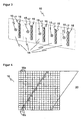
- FIG. 1 shows the basic structure of an embodiment of a multi-level sensor 10 according to the invention.
- a room area 12 is monitored by the multilevel sensor 10 by placing a plurality of monitoring levels 20 in the space area 12 and each of these levels 20 from its own known surface or level sensor 14 is monitored.
- a plurality of planes 20 two levels are sufficient in principle, however, the accuracy of the object detection increases when a larger number is provided.
- the space area 12 is a cuboid or a cube, and the planes are arranged parallel to each other at a regular interval 22. They act like a spatial light grid.
- the distance 22 between the planes 20 is selected according to the object size to be detected.
- the distance 22 may be about 7-10 mm for detecting fingers, 10-20 mm for detecting extremities, or 30-80 mm for detecting the lower extremities of a human body.
- the maximum size for the distance 22 depends on the safety class in the safety technology. There are applications conceivable in which the distance 22 is not regular. For example, at a working height in which one usually works with the hands, a much finer distance 22 could be provided than near the ground, where only feet have to be reckoned with. Also, the distance 22 could become finer with proximity to a source of danger.
- FIG. 2 illustrates a single area sensor 14 that makes up the multilevel sensor 10 and the level 20 it monitors.
- Such an area sensor 14 observing a plane 20 and monitoring within that level 20 a defined field of view for injury or the position of an object in that plane can determine is already known and can be made relatively inexpensive.
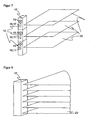
- FIG. 3 illustrates the internal structure of the multilevel sensor 10 in a view obliquely from the front.
- Each area sensor 14, of which the multilevel sensor 10 is constructed has a lighting 15 and an image sensor 16 with an associated optical system 17.
- the light source in the illumination 15 is a laser or an LED.
- a series of LEDs or a laser stack may also be provided.
- the light can also be pulled apart into the plane 20 by means of a diffractive optical element.
- the illumination 15 emits visible, ultraviolet or infrared light. In this case, visible light has the advantage that the monitored plane 20 can be recognized by operating personnel, whereas infrared or ultraviolet light does not disturb operators who work in the monitoring area 12.
- the image sensor 16 is a CCD or CMOS chip lying in the plane 20 in a line. If the viewing angle of the area sensor 14 is, for example, 90 °, this line is at a 45 ° angle, that is to say generally below half the viewing angle, in the plane 20.
- the image sensor 16 has a multiplicity of light-receiving elements arranged side by side depict the plane 20 in a line-shaped pixel image.
- a double image sensor for stereoscopic recording of the plane 20 can be understood.
- two line-shaped image sensors are adjacent to each other in the plane 20, thus taking them at a different angle and together form the image sensor 16.
- the stereoscopic image of the plane 20, which then record the two image sensors can be evaluated in this embodiment as a distance-resolved image. Further below, other alternative methods of determining distance will be described.
- the image sensor 16 can be made directly as a line-shaped, preferably integrated, chip.
- FIG. 4 shows an alternative with a matrix-shaped chip as an image sensor 16.
- a matrix-shaped image sensor 16 it is possible to use such a matrix-shaped image sensor 16 not only a plane 20, but to consider a slice of finite thickness of the monitoring area 12. But it can also, as now based on the FIG. 4 is to be explained, only one line of the matrix-shaped image sensor 16 to be active, so that the remaining light receiving elements 16a or pixels remain unused during operation. Since the production method for a line-shaped and a matrix-shaped chip is almost identical, a picture sensor 16 having a plurality of lines instead of a single line is hardly incurring higher costs.
- the image sensor 16 is illuminated in its receiving plane 20. Thus, it can be determined which light receiving elements 16b lie in the plane 20. Because this line in the FIG. 4 represented can take a rather irregular course over the matrix of the image sensor 16 and thus makes the evaluation more difficult, an adjustment process could ensure at least a right-angled position of the image sensor 16. This is relatively easy to accomplish because the image sensors 16 within the multilevel sensor 10 are aligned accordingly and a rectangular position of the multilevel sensor 10 is ensured to the plane 20 by a correspondingly regular housing of the multi-level sensor 10. After such a rough adjustment, the active light receiving elements 16b are located in a row or a column of the matrix-shaped chip. Instead of selecting a single line, the selection of several adjacent lines for monitoring level 20 is also conceivable.
- the light-receiving elements of the image sensor 16 can determine colored image values, gray values and / or distance signals. A method for determining distance will be described below in connection with FIGS. 6 and 7 described. In the case of distance determination, the necessary evaluation, for example in the form of an ASIC, can be assigned directly to the individual light-receiving element ("intelligent pixels").
- FIG. 5a an image sensor 16 is shown, which is associated with a lens 17 as optics.
- the solid and the dashed lines show, on which light receiving element or pixel receives light from different directions.
- the lens has a fairly large capture area and therefore emits a relatively large amount of light to the pixels onto which it images.
- a common lens 17 has a good energy balance and thus brightness resolution.
- a micro-optics 17 (“compound eye”) is assigned to the image sensor 16. Again, the solid or dashed lines indicate the respective capture range. Each lens of the micro-optics 17 passes less light than in the case of the common lens, so that the brightness resolution is slightly worse.
- the advantage of a micro-optic 17 is that it can be set much closer to the image sensor 16 and is also smaller in itself. This is a much more compact design possible.
- the optics 17 may be made of glass. But it can also be cast from plastic and made directly with the associated image sensor 16 as a module.
- the modules of the image sensors 16 with their associated optics 17 and optionally the lighting 15 may be mounted on a common rack or a circuit board. If a common power supply is then also provided for all modules, then this board, when used in a suitable housing, already represents the entire multilevel sensor 10.
- the modules 16, 17 are preferably assigned a common control.
- the common control can summarize an object detection of several image sensors 16 in different planes 20 and thus classify objects as dangerous or harmless ("intelligent muting").
- an object could be non-hazardous that breaks through planes 20 in a known manner, such as a moving pallet.
- the location of objects to each other can be evaluated and operators at his workplace in addition to a robot at a known distance be safe, but classified at decreasing distance as dangerous (“cooperative workstation").
- a color or gray scale image may be sufficient.
- the image sensor 16 for such embodiments of the invention may determine the distances using a light transit time method.
- FIG. 6 the construction of the multi-level sensor 10 with triangulating area sensors 14 is shown.
- the plane 20 to be observed is illuminated by the illumination 15 with a structured illumination pattern or a simple illumination line. This can be done for example by means of an upstream diffractive optical element or, in the case of the illumination line, as a laser line with a moving laser or a moving mirror (rad).
- the image sensor 16 is offset from the illumination 15 and placed obliquely.
- the positions of their image imaged by the optics 17 on the image sensor 16 is distance-dependent: the further away the remitting object is (ie the further to the right in FIG FIG. 6 ), the lower the image is on the image sensor 16 (the lower in FIG. 6 ).
- the line of the image sensor 16 is in the depth direction of FIG. 6 .
- the image sensor 16 thus has a shape that forms a row in the depth direction for imaging various areas in the plane 20 and in a height direction as shown in FIG FIG. 6 has one or more light-receiving elements for the triangulation.
- the height direction in each case a plurality of pixels or, for example, a differential photodiode can be used.
- a 180 ° viewing angle is provided for the triangulation in one embodiment of the invention.
- the distances, as now based on the FIG. 7 be determined with a light transit time method.
- the structure is so far inverse to that in the triangulation, as now the image sensors 16 are in the observed plane 20 and the illuminations 15, however, offset above or below or are arranged coplanar.
- time-of-flight procedures are known per se.
- the distance can be measured on the one hand over the duration of a light pulse or alternatively on the phase position of intensity-modulated light.
- a controller not shown, emits a light pulse by means of the illumination 15 and determines the transit time until it is received in the image sensor 16 and from it about the speed of light the distances.
- the illumination 15 emits intensity-modulated light of a known phase position and, via the phase shift on reception in the image sensor 16, determines the distances modulo the phase.
- FIG. 8 a multi-level sensor is shown whose levels are considered only up to a minimum distance.
- circle segments emerge as monitored planes 20. It is clear that such boundaries can be varied from plane to plane and also angle-dependent within a plane.
- monitoring areas 12 of almost any geometry can be generated, such as cones, cylinders, cuboids, cubes and more. Since the viewing angle is usually not 360 °, not necessarily cone and cylinder, but only part cone and part cylinder arise as the corresponding segments within the viewing angle.
- FIG. 9 It will be explained how distance conditions not only determine the outer boundary of the monitoring area 12, but also allow differentiations within the space area 12. Shown is an area sensor 14 with the associated observed plane 20 in plan view. In this level 20, a warning area 20a and a protection area 20b are defined. This serves to allow the multilevel sensor 10 to accept object engagement in the space area 12 as long as the warning area 20a or the protection area 20b is not damaged. If an object enters the warning area 20a, the multilevel sensor 10 reacts with a first escalation level, which may be, for example, a simple warning signal such as a sound or an alarm.
- a first escalation level which may be, for example, a simple warning signal such as a sound or an alarm.
- the multi-level sensor 10 reacts by eliminating a source of danger, for example switching off a dangerous machine.
- One of the purposes of this two-stage system is to reduce dead times caused by shutdown machines by alerting operating personnel in good time.
- the multilevel sensor 10 thus knows at which distance an object is located in the warning area 20a or in the protection area 20b.
- the spacing conditions also allow for blanking areas, such as locations where an object, such as a pallet or a measuring head, is allowed to enter without being objectionable.
- blanking areas can even be dynamic, that is, the distances are time-dependent or depend on previously detected objects. In this way, slow-moving objects or objects that are far from operating personnel can be detected as safe.
- FIG. 10a and 10b show a further variant of the invention.
- the surface sensors 14 have a viewing angle of 90 °. Of course, this does not have to be the case, but it is suitable for a cubic surveillance area 12 and a larger viewing angle is technically feasible only with increased effort.
- a plurality of image sensors 16 or the associated area sensors 14 are arranged next to one another so that their viewing angles add up. In a joint evaluation then effectively creates an area sensor 14 with a larger viewing angle.
- FIG. 10a shows an area sensor with an effective viewing angle of 180 ° from two area sensors 14
- FIG. 10b an area sensor with an effective viewing angle of 360 ° from four area sensors 14.
- FIG. 11a shows an embodiment of the invention, in which, although the surface sensors 14 lie on a common line, the planes 20 but fan-shaped apart.
- the plane spacing here depends on the distance to the multilevel sensor 10.
- a safety class that is to say a guaranteed maximum distance between the planes 20, is then fulfilled only up to a certain distance from the multilevel sensor 10. The advantage is that large obstacles can be detected earlier at a greater distance and the fineness of the object recognition then increases with increasing proximity.
- FIG. 11b shows an arrangement with mutually parading levels 20, but in which the surface sensors 14 are not arranged on a straight line, but a curve.
- the multilevel sensor 10 can cling to a curved surface and thus serve, for example, on a vehicle for collision protection ("electro-optical bumper").
- FIG. 11c shows a mixed form, in which the surface sensors 14 lie on a curve and the planes 20 run apart in a fan shape. This can be used on a vehicle to detect large-scale obstacles already at a great distance.
- FIG. 12 shows a particular embodiment of the invention, by means of which a dangerous machine such as a press brake 50 can be protected.
- a dangerous machine such as a press brake 50
- the inner portion 50a of the press brake 50 would have to be protected by a plurality of light grids respectively disposed at the corners of the inner portion 50a.
- a multilevel sensor 10 is provided, the planes 20 of which are set so that a total of a kind of cage results as a protective field.
- the big advantage of this arrangement is that the entire inner area 50a is free of hindering sensor components.
- monitoring can also be performed when bending boxes with side walls.
- the cage-like construction of the protection zone can be applied accordingly to other external geometries.
- FIG. 13 shows a further embodiment with vertically arranged planes 20 on a vehicle 60 (AGV, Automated Guided Vehicle).
- the surface sensors 14 advantageously have a viewing angle of 180 °.
- the resulting multilevel sensor 10 is therefore also suitable as a replacement for a mechanical bumper and detects a three-dimensional area in front of the vehicle.
- the area sensor such as a laser scanner
- FIG. 14 shows a further embodiment of the invention for measuring objects.
- the height of an object 70 may be determined by interrupting one or more planes 20.
- the other dimensions can be determined at least partially from the distances.
- Conventionally spatially upstream and thus disturbing light grids are used for a measurement of objects, for example, in front of a vertical circulation rack.
- cooperative boundaries of the surveillance area 12 may be provided. Particularly suitable for this are reflectors or contrast patterns. As long as their image or distance is correctly recognized in the image sensors 16, the image sensors 16 can be considered functional. If the multilevel sensor 10 monitors a free surveillance area 12, it would not be possible to verify if the surveillance area 12 is still free or the image sensor 16 is defective without such cooperative limitations.
Landscapes
- Physics & Mathematics (AREA)
- Engineering & Computer Science (AREA)
- Electromagnetism (AREA)
- Remote Sensing (AREA)
- General Physics & Mathematics (AREA)
- Radar, Positioning & Navigation (AREA)
- Computer Networks & Wireless Communication (AREA)
- General Engineering & Computer Science (AREA)
- Mechanical Engineering (AREA)
- Length Measuring Devices By Optical Means (AREA)
- Image Processing (AREA)
- Optical Radar Systems And Details Thereof (AREA)
- Measurement Of Optical Distance (AREA)
Abstract
Description
Die Erfindung betrifft einen optoeiektronischen Sensor sowie ein Verfahren zur Erfassung von Objekten nach den Oberbegriffen von Anspruch 1 beziehungsweise Anspruch 32.The invention relates to an optoelectronic sensor and a method for detecting objects according to the preambles of claim 1 and claim 32, respectively.
Eine automatisierte Überwachung eines Raumbereichs wird in einer Vielzahl von Anwendungen benötigt. Hierzu zählen beispielsweise Diebstahlsicherung, Automatisierungstechnik oder Sicherheitstechnik. Gerade zum Betrieb oder zur Absicherung von Maschinen muss regelmäßig die Anwesenheit eines Gegenstands oder Körperteils, häufig auch die Position eines solchen Gegenstands, innerhalb eines näherungsweise kubischen Raumes erkannt werden.Automated monitoring of a room area is needed in a variety of applications. These include, for example, theft protection, automation technology or safety technology. Especially for the operation or safeguarding of machinery, the presence of an object or part of the body, and often the position of such an object, must be regularly detected within an approximately cubic space.
Für die Überwachung eines dreidimensionalen Raumes wurden in der Vergangenheit eine Anzahl von Lösungen vorgeschlagen. Jede dieser Lösungen hat aber individuelle Schwächen, welche den Anwendungsbereich begrenzen.For monitoring a three-dimensional space, a number of solutions have been proposed in the past. However, each of these solutions has individual weaknesses that limit the scope.
So ist bekannt, den Raumbereich mit einer Kamera zu überwachen und beispielsweise das Bild dieser Kamera mit einem Referenzbild zu vergleichen, um auf Veränderungen in dem Raumbereich, wie beispielsweise das Eindringen von Objekten, reagieren zu können. Eine Weiterentwicklung solcher Lösungen ist die Aufnahme eines dreidimensionalen Kamerabildes. Dazu kann eine Doppelkamera und eine stereoskopische Auswertung verwendet werden, wie beispielsweise in der
Neben dem verhältnismäßig hohen Rechenaufwand bei derartigen stereoskopischen Verfahren hat diese Herangehensweise den Nachteil, dass die Überwachung aus einem Punkt heraus erfolgt. Dabei entsteht ein pyramiden- oder kegelförmiges Überwachungs-, beziehungsweise Messfeld. Ein kubischer Raumbereich innerhalb dieses Überwachungsfeldes schafft erhebliche Auswertungsprobteme. Außerdem können sich in dem Überwachungsraum Gegenstände (Paletten, Messköpfe oder dergleichen) befinden oder in ihn hineinragen. In deren Kernschatten entsteht dann ein großer, nicht überwachbarer Bereich.In addition to the relatively high computational effort in such stereoscopic methods, this approach has the disadvantage that the monitoring takes place from a point out. This creates a pyramid-shaped or conical monitoring or measuring field. A cubic space within this monitoring field creates considerable evaluation samples. In addition, objects (pallets, measuring heads or the like) may protrude or protrude into the surveillance space. In their core shadows, a large, non-observable area is created.
Eine andere herkömmliche Lösung ist in der
Es ist weiter bekannt, für eine abzusichernde Maschine eine Art Käfig aus mehreren Lichtgittem oder Scannern zu bilden. Dabei stehen zum Beispiel Lichtgittersäulen an den vier Ecken eines Quadrates und spannen somit die Seitenflächen eines Quaders auf. Der offensichtliche Nachteil hieran ist, dass mehrere Lichtgittersäulen benötigt werden. Diese behindern die Arbeit an der geschützten Maschine und verursachen höhere Kosten.It is also known to form for a machine to be backed a kind of cage from several Lichtgittem or scanners. Here are, for example, light grid columns at the four corners of a square and thus span the side surfaces of a cuboid. The obvious disadvantage of this is that several light grid columns are needed. These hinder the work on the protected machine and cause higher costs.
Schließlich ist eine Anzahl von Lösungen bekannt, eine einzelne Ebene zu überwachten. Das kann ein Lichtgitter, ein Laserscanner oder auch ein Triangulationssensor mit Kameraelement sein. Denkbar ist auch, einen entfernungsmessenden Bildsensor einzusetzen. Diese Sensoren können selbstverständlich nur eine Fläche und keinen Raum überwachen. Beispiele für derartige Sensoren sind in der
Die
Aus der
In der
Aus der
In der
In der
Es ist daher Aufgabe der Erfindung, einen zuverlässigen Sensor zur Überwachung eines dreidimensionalen Raumbereichs anzugeben, dessen Überwachungsfunktion von Gegenständen in dem Raumbereich und umgekehrt der Raumbereich von dem Sensor selbst möglichst ungestört bleibt.It is therefore an object of the invention to provide a reliable sensor for monitoring a three-dimensional space region whose monitoring function of objects in the spatial area and vice versa, the spatial area of the sensor itself remains undisturbed as possible.
Diese Aufgabe wird durch einen Sensor und ein Verfahren zur Erfassung von Objekten in einem Raumbereich gemäß Anspruch 1 beziehungsweise Anspruch 28 gelöst. Die erfindungsgemäße Lösung hat den Vorteil, dass ein Raumbereich mit durch die Anzahl der Ebenen einstellbarer Genauigkeit überwacht werden kann, ohne dass eine Abschattung eines Bildsensors dazu führt, weite Teilbereiche nicht mehr erkennen zu können. Somit können Gegenstände unter Erhaltung der Funktionsfähigkeit des Sensors berücksichtigt werden, die in dem überwachten Raumbereich vorhanden sind und vorhanden sein sollen. Der Sensor ist kompakt und lässt den Randbereich des überwachten Bereichs anders als eine Vielzahl von Lichtgittern oder Scannern weitgehend frei. Außerdem ist der Sensor kostengünstig herzustellen und benötigt gegenüber der Beobachtung eines Raumbereichs nur deutlich einfachere und zuverlässigere Auswertungsverfahren.This object is achieved by a sensor and a method for detecting objects in a spatial area according to claim 1 or claim 28. The solution according to the invention has the advantage that a spatial region can be monitored with accuracy that can be set by the number of planes, without the shadowing of an image sensor resulting in the fact that it is no longer possible to recognize large subregions. Thus, objects can be considered while preserving the functionality of the sensor that is and should be present in the monitored space area. The sensor is compact and, unlike a variety of light curtains or scanners, leaves the edge area of the monitored area largely blank. In addition, the sensor is inexpensive to manufacture and requires compared to the observation of a spatial area only much simpler and more reliable evaluation.
Die Erfindung geht dabei von der Grundidee aus, bekannte kostengünstige Flächensensoren zu erweitern. Mit einer Vervielfältigung und geeigneten Anordnung solcher Sensoren wird auch die Überwachung eines dreidimensionalen Raumbereichs ermöglicht.The invention is based on the basic idea of expanding known cost-effective area sensors. With a duplication and suitable arrangement of such sensors also the monitoring of a three-dimensional space area is made possible.
Bevorzugt sind die Bildsensoren so angeordnet, dass die Ebenen untereinander überlappungsfrei und im Wesentlichen parallel zueinander sind oder voneinander fächerförmig von den Bildsensoren ausgehend auseinander laufen. Mit dieser Anordnung lassen sich einerseits bei paralleler Ausrichtung quader- oder würfelförmige Bereiche auf einfache Weise überwachen und andererseits bei fächerförmigem Auseinanderlaufen ein überwachter Raumbereich einstellen, der mit zunehmender Nähe zum Sensor genauer überwacht wird.The image sensors are preferably arranged such that the planes are mutually overlapping-free and substantially parallel to one another or run apart in a fan-shaped manner starting from the image sensors. With this arrangement, cuboid or cube-shaped areas can be monitored in a simple manner with parallel alignment on the one hand, and on the other hand, with fan-shaped divergence, a monitored spatial area can be set which is monitored more closely with increasing proximity to the sensor.
Noch bevorzugter sind die Bildsensoren so angeordnet, dass je zwei Ebenen zumindest in einem Teilbereich des Überwachungsbereichs voneinander höchstens um einen jeweiligen vorgegebenen Abstand beabstandet sind. Damit lässt sich die gewünschte Objektauflösung des Sensors einstellen und daraus eine Balance zwischen Kosten für eine größere Vielzahl von Sensoren und Erkennungsgenauigkeit einstellen.More preferably, the image sensors are arranged so that at least two levels are at least in a partial area of the monitored area spaced from each other at most by a respective predetermined distance. This allows the desired object resolution of the sensor to be set and a balance therefrom between costs for a greater variety of sensors and detection accuracy.
Noch bevorzugter beträgt der vorgegebene Abstand jeweils 7-10 mm zur Detektion von Fingern, 10-20 mm zu Detektion von Extremitäten oder 30-80 mm zur Detektion der unteren Extremitäten eines menschlichen Körpers. Dies sind typische Abstände für die Erfüllung einer Sicherheitsanforderung, die von der Anwendung abhängt.More preferably, the predetermined distance is 7-10 mm for detecting fingers, 10-20 mm for detecting extremities, or 30-80 mm for detecting the lower extremities of a human body. These are typical intervals for meeting a security requirement that depends on the application.
Vorteilhafterweise sind die Bildsensoren auf einer Geraden oder einer Kurve aufgereiht angeordnet. Das ermöglicht in dem einen Fall den Aufbau eines einfachen, geraden Sensors und in dem anderen Fall die Anpassung des Sensors an die Geometrie seines Anbringungsortes beziehungsweise des zu überwachenden Raumbereichs.Advantageously, the image sensors are arranged on a straight line or a curve. This allows in one case, the construction of a simple, straight sensor and in the other case, the adaptation of the sensor to the geometry of its mounting location or the space to be monitored area.
Bevorzugt ist jedem Bildsensor eine Lichtquelle zugeordnet, insbesondere ein Laser oder eine LED. Die Ausleuchtung des Raumbereichs ist nicht unbedingt durch das Umgebungslicht oder eine externe Beleuchtung sichergestellt. Darüber hinaus hat eine sensoreigene Lichtquelle bekannte Eigenschaften des ausgesandten Lichts, welche die Auswertung erleichtern oder sogar erst ermöglichen.Each image sensor is preferably associated with a light source, in particular a laser or an LED. The illumination of the room area is not necessarily ensured by the ambient light or external lighting. In addition, a sensor-own light source has known properties of the emitted light, which facilitate the evaluation or even make it possible.
Noch bevorzugter ist die Lichtquelle eine Lichtquelle für sichtbares, infrarotes oder ultraviolettes Licht. Je nach Anwendungsbereich kann es vorteilhaft sein, die Beleuchtung zu sehen oder unsichtbar zu machen.More preferably, the light source is a visible, infrared or ultraviolet light source. Depending on the application, it may be advantageous to see the lighting or make it invisible.
Vorteilhafterweise nehmen die Bildsensoren ein entfernungsaufgelöstes Pixelbild auf. Damit ist nicht mehr nur bekannt, ob ein Objekt in einer Ebene vorhanden ist, sondern auch wo. Damit lässt sich viel feiner klassifizieren, ob das Objekt in dem Überwachungsbereich erlaubt ist oder nicht.Advantageously, the image sensors record a distance-resolved pixel image. This no longer only tells you whether an object exists in a layer, but also where. This makes it much easier to classify whether or not the object is allowed in the surveillance area.
Bevorzugt ist die Lichtquelle dafür ausgebildet, in die Ebene des zugehörigen Bildsensors ein strukturiertes Beleuchtungsmuster oder eine Beleuchtungslinie zu strahlen, insbesondere mittels eines in den Strahlengang der Lichtquelle eingebrachten diffraktiven optischen Elements und der Bildsensor kann die Entfernungen mittels Triangulation bestimmen. Mit einer solchen Lichtquelle ist ein entfernungsaufgelöstes Bild mit den bekannten Verfahren der Triangulation zuverlässig umsetzbar.The light source is preferably designed to radiate a structured illumination pattern or a line of illumination into the plane of the associated image sensor, in particular by means of a diffractive optical element introduced into the beam path of the light source, and the image sensor can determine the distances by means of triangulation. With such a light source, a distance-resolved image can be reliably implemented with the known methods of triangulation.
Alternativ können die Lichtempfangselemente der Bildsensoren die Entfernungen nach einem Lichtlaufzeitverfahren bestimmen. Dies ist ein anderes bekanntes und zuverlässiges Verfahren zur Entfernungsbestimmung. Somit können bekannte Bildsensoren eingesetzt werden.Alternatively, the light receiving elements of the image sensors may determine the distances according to a light transit time method. This is another known and reliable method for determining distance. Thus, known image sensors can be used.
Dabei können die Lichtquellen bevorzugt Lichtpulse aussenden und die Lichtempfangselemente die Pulslaufzeit bestimmen. Dies ist ein robustes und bekanntes Verfahren zur Bestimmung der Entfernung mit einem Lichtlaufzeitverfahren.In this case, the light sources can preferably emit light pulses and the light receiving elements determine the pulse transit time. This is a robust and well-known method for determining the distance with a light transit time method.
Alternativ senden die Lichtquellen ein intensitätsmoduliertes Licht aus und die Lichtempfangselemente können dessen Phasenverschiebung bestimmen. Dies ist ein weiteres robustes und bekanntes Licht auf Zeitverfahren. Bei einem herkömmlichen Bildsensor kann ein PMD (Photonmischdetektor) mit einer Ladungsschaukel in jedem Pixel eingesetzt werden, über deren Ladungsverhältnis die Phase des modulierten Messlichts und daraus die Lichtlaufzeit bestimmt wird.Alternatively, the light sources emit an intensity-modulated light and the light-receiving elements can determine its phase shift. This is another robust and well-known light on time trial. In a conventional image sensor, a PMD (Photonmischdetektor) can be used with a charge swing in each pixel over the charge ratio, the phase of the modulated measurement light and from it the light transit time is determined.
Vorteilhafterweise ist der Sensor für die Überwachung eines Schutzbereichs ausgebildet, der Teilbereich des Überwachungsbereichs ist, indem die Steuerung jeder Ebene winkelabhängige Schutzbereich-Abstandsbedingungen zuweist und ein erfasstes Objekt als den Schutzbereich verletzend erkennt, wenn es die Schutzbereich-Abstandsbedingungen erfüllt. Mit solchen Abstandsbedingungen lässt sich in jeder Ebene eine Vielzahl von Geometrien für den Schutzbereich umsetzen und somit anwendungsspezifisch definieren, in welchen Teil des Überwachungsbereichs keine Objekte eindringen dürfen. Der Schutzbereich ist also nicht allein durch die Anordnung der Bildsensoren und äußere Begrenzungen festgelegt, sondern kann konfiguriert werden.Advantageously, the sensor is configured to monitor a protection area that is part of the surveillance area by the controller assigning angle-dependent guard area clearance conditions to each plane and recognizing a detected object as violating the protection area if it meets the guard area clearance conditions. With such distance conditions, a large number of geometries for the protected area can be implemented in each level, and thus application-specific define in which part of the surveillance area no objects are allowed to penetrate. The scope of protection is therefore not determined solely by the arrangement of the image sensors and external boundaries, but can be configured.
Dabei ist bevorzugt der Sensor für die Überwachung eines Warnbereichs ausgebildet, der als Teilbereich des Überwachungsbereichs den Schutzbereich umfasst, indem die Steuerung jeder Ebene winkelabhängige Warnbereich-Abstandsbedingungen zuweist und ein erfasstes Objekt als den Warnbereich verletzend erkennt, wenn es die Warnbereich-Abstandsbedingungen erfüllt. Für die Konfigurationsmöglichkeiten des Warnbereichs gilt dasselbe wie für den Schutzbereich. Der Warnbereich ermöglicht eine Abstufung, bei der ein Eindringen von Objekten eine mildere Reaktion hervorruft, als eine Schutzbereichsverletzung.In this case, the sensor is preferably designed for monitoring a warning area, which as a subarea of the monitoring area comprises the protected area by the controller assigning angle-dependent warning area distance conditions to each level and recognizing a detected object as violating the warning area if it fulfills the warning area distance conditions. The same applies to the configuration options of the warning area as to the protection area. The warning range allows for grading where intrusion of objects causes a milder response than a guard violation.
In einer Anwendung des Sensors zur Absicherung eines Gefahrenbereichs ist die Steuerung bevorzugt für die Abgabe eines Warnsignals ausgebildet, wenn der Warnbereich verletzt ist. So kann beispielsweise eine Verletzung des Warnbereichs lediglich ein Warnsignal verursachen, während eine Verletzung des Schutzbereichs unmittelbar zu einem Abschalten der geschützten Maschine führt.In an application of the sensor to secure a danger zone, the controller is preferably designed for the delivery of a warning signal when the warning area is violated. For example, a violation of the warning area can only cause a warning signal, while a violation of the protection area immediately leads to a shutdown of the protected machine.
Vorteilhafterweise sind die Schutzbereich-Abstandsbedingungen beziehungsweise die Warnbereich-Abstandsbedingungen in mehreren oder allen Ebenen in zumindest einem Winkelbereich gleich. Schutzbereich und Warnbereich müssen also nicht in jeder Ebene konfiguriert werden, sondern werden zwischen den Ebenen kopiert. Das erleichtert zum einen die Auswertung und Einrichtung, zum anderen können Begrenzungen des oder der Gegenstände im Überwachungsbereich, die mehrere Ebenen betreffen, auf einfache Weise berücksichtigt werden.Advantageously, the protection range spacing conditions or the warning range spacing conditions are the same in several or all planes in at least one angle range. The protection area and the warning area do not have to be configured in every level, but are copied between the levels. On the one hand, this facilitates the evaluation and setup, on the other hand, limitations of the object or objects in the surveillance area, which concern several levels, can be taken into account in a simple manner.
Dabei ist der Schutzbereich beziehungsweise der Warnbereich bevorzugt ein Würfel, ein Quader, ein Teilkegel, ein Teilzylinder oder ein würfelförmiger, quaderförmiger, teilkegelförmiger oder teilzylinderformiger Käfig. Solche Geometrien lassen sich über die Abstandsbedingungen leicht konfigurieren. Alternativ kann ein Teil der Geometrie durch eine äußere Begrenzung gegeben sein, etwa eine gemeinsame Kante.In this case, the protected area or the warning area is preferably a cube, a cuboid, a partial cone, a partial cylinder or a cube-shaped, cuboid, partially cone-shaped or teilzylinderformiger cage. Such geometries can be easily configured via the distance conditions. Alternatively, part of the geometry may be given by an outer boundary, such as a common edge.
Bevorzugt hat jeder Bildsensor einen Sichtwinkel von 90°. Das ist technisch leicht umsetzbar und geeignet für den wichtigen Fall eines quaderförmigen Überwachungsbereichs. Alternativ ist jedem Bildsensor eine Panoramaoptik zugeordnet und der Bildsensor hat somit einen Sichtwinkel von 360°. Damit kann der Bildsensor einen wesentlich größeren Überwachungsbereich aufnehmen.Preferably, each image sensor has a viewing angle of 90 °. This is technically easy to implement and suitable for the important case of a cuboid monitoring area. Alternatively, each image sensor is assigned a panoramic lens and the image sensor thus has a viewing angle of 360 °. This allows the image sensor to record a much larger surveillance area.
Bevorzugt ist neben jedem Bildsensor mindestens ein weiterer zugeordneter Bildsensor derart angeordnet, dass sich die Sichtwinkel der einander zugeordneten Bildsensoren addieren. Dies ist eine Alternative zu einer verhältnismäßig kostenaufwändigen Panoramaoptik und ermöglicht beliebige Sichtwinkel des Sensors.At least one further assigned image sensor is preferably arranged next to each image sensor such that the viewing angles of the associated image sensors add up. This is an alternative to a relatively expensive panoramic look and allows any viewing angle of the sensor.
Vorteilhafterweise weist jeder Bildsensor einen CCD- oder einen CMOS-Chip mit mehreren Zeilen auf und in einer Einlernphase kann zur einfachen Justierung diejenige Zeile oder können diejenigen Zeilen für den Betrieb ausgewählt werden, welche die zugehörige Ebene überwacht. Die Kosten bei der Herstellung eines Bildsensors mit mehreren Zeilen gegenüber einem solchen mit nur einer Zeile sind nur geringfügig erhöht. Die Auswahl der richtigen Zeile in einer Einlernphase erhöht die Bedienerfreundlichkeit bei der Justage erheblich.Advantageously, each image sensor has a CCD or a CMOS chip with several lines, and in a teach-in phase, that line or those lines which monitors the associated level can be selected for easy adjustment for easy adjustment. The cost of making a Image sensors with several lines compared to those with only one line are only slightly increased. The selection of the correct line in a training phase considerably increases the user-friendliness during the adjustment.
Bevorzugt ist den Lichtempfangselementen eines jeden Bildsensors eine gemeinsame Optik zugeordnet. Diese hat eine hohe Lichtausbeute und ermöglicht, den Überwachungsbereich geeignet auf dem Bildsensor abzubilden.Preferably, the light receiving elements of each image sensor associated with a common optics. This has a high luminous efficacy and makes it possible to image the monitoring area appropriately on the image sensor.
Alternativ ist Gruppen von Lichtempfangselementen jedes Bildsensors eine Mikrooptik zugeordnet und Bildsensor und Mikrooptiken bilden als ein Bauteil ein gemeinsames Modul. Die Mikrooptiken leiten jeweils etwas weniger Licht auf ein Lichtempfangselement, ermöglichen aber eine wesentlich kompaktere und preisgünstigere Bauweise.Alternatively, groups of light-receiving elements of each image sensor are associated with a micro-optic and image sensor and micro-optics form a common module as a component. The micro-optics each direct slightly less light to a light-receiving element, but allow a much more compact and cheaper construction.
Vorteilhafterweise sind mehrere Bildsensoren oder mehrere gemeinsame Module auf einem gemeinsamen Baugruppenträger angeordnet. Dies ermöglicht eine einfache, kostengünstige und gemeinsame Herstellung der Bildsensoren.Advantageously, a plurality of image sensors or a plurality of common modules are arranged on a common rack. This enables a simple, cost-effective and joint production of the image sensors.
Bevorzugt weisen dabei die Steuerung, die Bildsensoren und die Lichtquellen eine gemeinsame Energieversorgung auf. Auch damit kann der Sensor als Ganzes kompakter gebaut und angeschlossen werden.In this case, the controller, the image sensors and the light sources preferably have a common energy supply. Even so, the sensor as a whole can be made more compact and connected.
Vorteilhafterweise ist eine gemeinsame Steuerung für mehrere oder für alle Bildsensoren vorgesehen. Dies ermöglicht erneut eine kompaktere Bauweise und eine Kostenersparnis.Advantageously, a common control for several or all image sensors is provided. This again allows a more compact design and cost savings.
Dabei ist die gemeinsame Steuerung bevorzugt dafür ausgebildet, eine Objekterfassung durch mehrere Bildsensoren in unterschiedlichen Ebenen zu einer geometrischen Objektklassifizierung zusammenzufassen und nur bestimmte Objektklassen als Gefährdung zu werten. Es gibt Gegenstände wie Paletten oder Arbeitsgeräte, die in dem Überwachungsbereich vorhanden sind und sein dürfen und die in mehreren Ebenen erkannt werden. Die gemeinsame Steuerung ermöglicht dann, auch solche Objekte zu klassifizieren und gegebenenfalls nicht auf sie zu reagieren.In this case, the common control is preferably designed to combine an object detection by a plurality of image sensors in different levels into a geometrical object classification and to evaluate only certain object classes as a hazard. There are items such as pallets or implements that are and may be present in the surveillance area and that are detected in multiple levels. The joint control then makes it possible to classify even such objects and, if necessary, not to respond to them.
Bevorzugt ist die gemeinsame Steuerung dafür ausgebildet, Objekterfassungen durch mehrere Bildsensoren für eine Klassifizierung der Lage von Objekten zueinander sowie deren zeitliche Veränderung als Bewegung zusammenzufassen und bestimmte Objektlagen oder Bewegungen als Gefährdung zu werten. Beispielsweise kann ein Roboter neben Bedienpersonal unbedenklich sein, wird aber gefährlich, wenn er sich mit einer zu großen Geschwindigkeit dem Bedienpersonal nähert. Erst im letzteren Falle soll der Sensor reagieren. Ebenso kann eine Gefahrenquelle in einem gewissen Abstand zum Bedienpersonal zum gewöhnlichen Ablauf gehören, muss bei Unterschreitung eines Abstandes aber zu einem Erkennen einer Gefährdung führen.Preferably, the common control is designed to summarize object captures by several image sensors for a classification of the position of objects to each other and their temporal change as a movement and evaluate certain object situations or movements as a threat. For example, a robot in addition to operating personnel can be safe, but is dangerous if he approaches the operator at too high a speed. Only in the latter case should the sensor react. Likewise, a source of danger at a certain distance from the operating personnel may be part of the normal procedure, but must lead to recognition of a hazard if the distance is not reached.
In einer weiteren Ausführungsform der Erfindung sind kooperative Begrenzungen des Überwachungsbereichs vorgesehen und die Steuerung dafür ausgebildet, deren Bild beziehungsweise Entfernung als Funktionstest der Bildsensoren mit einem Referenzbild beziehungsweise Referenzentfernungen zu vergleichen. Wenn der Bildsensor nämlich "ins Leere" sieht, kann ansonsten nicht zwischen einer Fehlfunktion des Bildsensors und einem nach wie vor leeren Bild unterschieden werden. Die Funktionsfähigkeit des Bildsensors kann mithilfe der kooperativen Begrenzungen unabhängig von der Szenerie im Überwachungsbereich überprüft werden.In a further embodiment of the invention, cooperative limitations of the monitoring area are provided and the controller is designed to compare its image or distance as a function test of the image sensors with a reference image or reference distances. If the image sensor sees "in the void", it is otherwise impossible to distinguish between a malfunction of the image sensor and a still empty image. The functioning of the image sensor can be checked using the cooperative limitations regardless of the scene in the surveillance area.
In einer weiteren Ausführungsform wird der Sensor mobil an einem Fahrzeug oder einem Roboter verwendet. Als Alternative zu einer statischen Aufstellung des Sensors können somit zum Beispiel Hindernisse oder Personen im Fahrweg des Fahrzeugs oder Roboters erkannt werden.In another embodiment, the sensor is used mobile on a vehicle or a robot. As an alternative to a static mounting of the sensor thus obstacles or people can be detected in the travel of the vehicle or robot, for example.
In einer weiteren Ausführungsform wird der Sensor für die Vermessung von Objekten in dem Überwachungsbereich eingesetzt. Über die Anzahl und den Abstand der von dem Objekt durchstoßenen Ebenen kann dessen Höhe, über die Entfernungen innerhalb einer Ebene zumindest bei kontrastreichen Objekten bekannter Abmessungen auch die sonstige Größe bestimmt werden.In another embodiment, the sensor is used to measure objects in the surveillance area. The height and height of the object can be determined by the number and the distance of the planes pierced by the object Distances within a plane at least for high-contrast objects of known dimensions and the other size to be determined.
Das erfindungsgemäße Verfahren kann beispielhaft, aber nicht abschließend, mit analogen Merkmalen fortgebildet werden, wie sie für den Sensor in den Unteransprüchen angegeben sind und zeigt dabei ähnliche Vorteile.The inventive method can be exemplified, but not exhaustive, trained with analogous features, as they are given for the sensor in the dependent claims and shows similar advantages.
Die Erfindung wird nachstehend auch hinsichtlich weiterer Merkmale und Vorteile beispielhaft anhand von Ausführungsformen und unter Bezug auf die beigefügte Zeichnung näher erläutert. Die Abbildungen der Zeichnung zeigen in:
- Fig. 1
- eine dreidimensionale Schemadarstellung einer Ausführungsform des erfindungsgemäßen Mehrebenensensors;
- Fig.2
- eine dreidimensionale Schemadarstellung zur Erläuterung eines einzelnen Flächenelements des Mehrebenensensors;
- Fig. 3
- eine Innenansicht des Aufbaus des Mehrebenensensors von schräg vorn;
- Fig. 4
- eine erläuternde Darstellung zum Einlernen der Lichtempfangselemente der empfangenden Zeile eines Bildsensors;
- Fig. 5a
- eine Darstellung der Empfangsoptik eines Bildsensors mit einer gemeinsamen Linse;
- Fig. 5b
- eine Darstellung der Empfangsoptik eines Bildsensors mit einer Mikrooptik;
- Fig. 6
- eine dreidimensionale Schemadarstellung des Mehrebenensensors mit Entfernungsmessung durch Triangulation;
- Fig. 7
- eine dreidimensionale Schemadarstellung des Mehrebenensensors mit Entfernungsmessung durch Lichtlaufzeitverfahren;
- Fig. 8
- eine dreidimensionale Schemadarstellung des Mehrebenensensors mit Höchstabstand für den Überwachungsbereich;
- Fig. 9
- eine Draufsicht auf eine Ebene mit einem Warnbereich und einem Schutzbereich zur Erläuterung der Abstandsbedingungen;
- Fig. 10a
- eine Darstellung zur Erläuterung der Erweiterung des Sichtwinkels durch zwei Bildsensoren;
- Fig. 10b
- eine Darstellung zur Erläuterung der Erweiterung des Sichtwinkels durch mehrere Bildsensoren auf 360°;
- Fig.11a
- eine Darstellung eines Mehrebenensensors mit fächerförmig angeordneten Ebenen;
- Fig. 11b
- eine Darstellung eines Mehrebenensensors mit auf einer Kurve angeordneten Bildsensoren und parallelen Ebenen;
- Fig. 11c
- eine Darstellung eines Mehrebenensensors mit auf einer Kurve angeordneten Bildsensoren und fächerförmig angeordneten Ebenen;
- Fig. 12
- eine Darstellung eines käfigartigen, quaderförmigen Schutzfeldes;
- Fig. 13
- eine Darstellung der senkrechten Anbringung des Mehrebenensensors an einem Fahrzeug; und
- Fig. 14
- eine Darstellung zur Erläuterung der Verwendung des Mehrebenensensors für die Vermessung von Objekten.
- Fig. 1
- a three-dimensional schematic representation of an embodiment of the multi-level sensor according to the invention;
- Fig.2
- a three-dimensional schematic representation for explaining a single surface element of the multi-level sensor;
- Fig. 3
- an interior view of the structure of the multi-level sensor obliquely from the front;
- Fig. 4
- an explanatory diagram for teaching the light receiving elements of the receiving line of an image sensor;
- Fig. 5a
- a representation of the receiving optics of an image sensor with a common lens;
- Fig. 5b
- a representation of the receiving optics of an image sensor with a micro-optics;
- Fig. 6
- a three-dimensional schematic representation of the multi-level sensor with distance measurement by triangulation;
- Fig. 7
- a three-dimensional schematic representation of the multi-level sensor with distance measurement by light transit time method;
- Fig. 8
- a three-dimensional schematic representation of the multi-level sensor with maximum distance for the monitoring area;
- Fig. 9
- a plan view of a plane with a warning area and a protection area for explaining the distance conditions;
- Fig. 10a
- a representation for explaining the extension of the viewing angle by two image sensors;
- Fig. 10b
- a representation for explaining the extension of the viewing angle by several image sensors to 360 °;
- 11A
- a representation of a multi-level sensor with fan-shaped planes;
- Fig. 11b
- a representation of a multi-level sensor with arranged on a curve image sensors and parallel planes;
- Fig. 11c
- a representation of a multi-level sensor with arranged on a curve image sensors and fan-shaped planes;
- Fig. 12
- a representation of a cage-like, cuboid protective field;
- Fig. 13
- a representation of the vertical attachment of the multi-level sensor to a vehicle; and
- Fig. 14
- a representation for explaining the use of the multi-level sensor for the measurement of objects.
Der Abstand 22 der Ebenen 20 untereinander ist entsprechend der zu detektierenden Objektgröße gewählt. Der Abstand 22 kann etwa 7-10 mm zur Detektion von Fingern, 10-20 mm zu Detektion von Extremitäten oder 30-80 mm zur Detektion der unteren Extremitäten eines menschlichen Körpers betragen. Natürlich sind andere Abstände zur Detektion anderer Objekte denkbar. Die Höchstgröße für den Abstand 22 hängt in der Sicherheitstechnik von der Sicherheitsklasse ab. Es sind Anwendungen denkbar, bei denen der Abstand 22 nicht regelmäßig ist. So könnte etwa in einer Arbeitshöhe, in der normalerweise mit den Händen gearbeitet wird, ein deutlich feinerer Abstand 22 vorgesehen sein als in Bodennähe, wo nur mit Füßen gerechnet werden muss. Auch könnte der Abstand 22 mit der Nähe zu einer Gefahrenquelle feiner werden.The
Die
Der Bildsensor 16 ist ein CCD- oder CMOS-Chip, der zeilenförmig in der Ebene 20 liegt. Diese Zeile liegt, wenn der Sichtwinkel des Flächensensors 14 beispielsweise 90° beträgt, unter einem 45°-Winkel, allgemein also bevorzugt unter dem halben Sichtwinkel, in der Ebene 20. Der Bildsensor 16 weist eine Vielzahl von nebeneinander liegenden Lichtempfangselementen auf, die somit in einem zeilenförmigen Pixelbild die Ebene 20 abbilden.The
Als Bildsensor 16 kann auch ein doppelter Bildsensor zur stereoskopischen Aufnahme der Ebene 20 verstanden werden. Dazu liegen beispielsweise zwei zeilenförmige Bildsensoren nebeneinander in der Ebene 20, nehmen diese somit unter versetztem Blickwinkel auf und bilden gemeinsam den Bildsensor 16. Das stereoskopische Bild der Ebene 20, das die beiden Bildsensoren dann aufnehmen, kann in dieser Ausführungsform als entfernungsaufgelöstes Bild ausgewertet werden. Weiter unten werden noch weitere alternative Verfahren zur Entfernungsbestimmung beschrieben.As
Der Bildsensor 16 kann unmittelbar als ein zeilenförmiger, vorzugsweise integrierter, Chip hergestellt sein.
Um die als aktiv auszuwählenden Lichtempfangselemente 16b aufzufinden, wird der Bildsensor 16 in seiner Empfangsebene 20 beleuchtet. Somit kann festgestellt werden, welche Lichtempfangselemente 16b in der Ebene 20 liegen. Da diese Linie in der
Die Lichtempfangselemente des Bildsensors 16 können farbige Bildwerte, Grauwerte und/oder Entfernungssignale bestimmen. Ein Verfahren zur Entfernungsbestimmung wird weiter unten im Zusammenhang mit den
In
In
Die Optik 17 kann aus Glas bestehen. Sie kann aber auch aus Kunststoff gegossen und unmittelbar mit dem zugehörigen Bildsensor 16 als ein Modul hergestellt werden. Die Module aus den Bildsensoren 16 mit ihrer zugeordneten Optik 17 und gegebenenfalls der Beleuchtung 15 können auf einem gemeinsamen Baugruppenträger oder einer Platine montiert sein. Ist dann auch noch eine gemeinsame Stromversorgung für alle Module vorgesehen, so stellt diese Platine dann, in ein geeignetes Gehäuse eingesetzt, bereits den gesamten Mehrebenensensor 10 dar.The
Dabei ist den Modulen 16, 17 bevorzugt eine gemeinsame Steuerung zugeordnet. Die gemeinsame Steuerung kann eine Objekterfassung mehrerer Bildsensoren 16 in unterschiedlichen Ebenen 20 zusammenfassen und auf diese Weise Objekte als gefährlich oder ungefährlich klassifizieren ("intelligentes Muting"). Ungefährlich könnte beispielsweise ein Objekt sein, dass in bekannter Weise Ebenen 20 durchbricht, wie eine durchfahrende Palette. Auf ähnliche Weise kann auch die Lage von Objekten zueinander ausgewertet werden und Bedienpersonal an seinem Arbeitsplatz neben einem Roboter bei bekanntem Abstand ungefährlich sein, bei sich verringerndem Abstand aber als gefährlich klassifiziert werden ("kooperativer Arbeitsplatz").In this case, the
In einigen Anwendungen kann ein farbiges oder ein Grauwertbild ausreichend sein. Eine größere Vielfalt an Anwendungen ergibt sich, wenn neben den Grauwerten auch die Entfernungen gemessen werden. Der Bildsensor 16 kann für solche Ausführungsformen der Erfindung die Entfernungen mithilfe eines Lichtlaufzeitverfahrens bestimmen.In some applications, a color or gray scale image may be sufficient. A wider variety of applications arises when, in addition to gray levels also the distances are measured. The
Hierzu ist in
Wie man unter Heranziehen der Darstellung in
Alternativ können die Entfernungen, wie nunmehr anhand der
Die Entfernungsmessung ermöglicht nun weitere Ausführungsformen der Erfindung. In
Anhand der
Um den Warnbereich 20a und den Schutzbereich 20b zu erkennen, sind zu Sichtlinien 30 in verschiedenen Winkeln zugehörige Abstände 30a-e eingelernt. Der Mehrebenensensor 10 weiß somit, bei welcher Entfernung sich ein Objekt im Warnbereich 20a oder im Schutzbereich 20b befindet.In order to detect the
Die Abstandsbedingungen erlauben auch Ausblendungsbereiche, beispielsweise Orte, wo ein Objekt wie eine Palette oder ein Messkopf eindringen darf, ohne dass dies ein verletzender Objekteingriff ist. Solche Ausblendungsbereiche können sogar dynamisch sein, das heißt die Abstände sind zeitabhängig oder hängen von früher erkannten Objekten ab. Auf diese Weise können langsam fahrende Objekte oder Objekte, die sich fern von Bedienpersonal aufhalten, als ungefährlich erkannt werden.The spacing conditions also allow for blanking areas, such as locations where an object, such as a pallet or a measuring head, is allowed to enter without being objectionable. Such blanking areas can even be dynamic, that is, the distances are time-dependent or depend on previously detected objects. In this way, slow-moving objects or objects that are far from operating personnel can be detected as safe.
Die
Bei den bisherigen Ausführungsformen lagen die Ebenen 20 parallel zueinander und die Flächensensoren 14 auf einer gemeinsamen Geraden.
Um die Funktionsfähigkeit des Mehrebenensensors 10 sicherzustellen, können kooperative Begrenzungen des Überwachungsbereichs 12 vorgesehen werden. Besonders geeignet hierfür sind Reflektoren oder Kontrastmuster. Solange deren Bild beziehungsweise Entfernung in den Bildsensoren 16 richtig erkannt wird, können die Bildsensoren 16 als funktionsfähig gelten. Wenn der Mehrebenensensor 10 einen freien Überwachungsbereich 12 überwacht, könnte ohne derartige kooperative Begrenzungen nicht überprüft werden, ob der Überwachungsbereich 12 weiterhin frei ist oder der Bildsensor 16 defekt.To ensure the operability of the
Die beschriebenen Ausführungsformen sind beispielhaft zu verstehen. Die Erfindung umfasst insbesondere auch solche Ausführungsformen, bei denen beschriebene Merkmale anders kombiniert sind.The described embodiments are to be understood by way of example. In particular, the invention also includes such embodiments in which described features are combined differently.
Claims (28)
- An optoelectronic sensor (10) for detecting an object in a three-dimensional monitored region (12) by at least one image sensor (16) that can take a pixel image of the monitored region (12) by means of a plurality of light-receiving elements and comprising at least one control unit configured to detect an object from image data of the pixel image, wherein a plurality of image sensors (16) is provided, each image sensor (16) including at least one pixel line formed by light-receiving elements (16b), and wherein the image sensors (16) are spaced from each other so that each image sensor (16) can monitor an associated plane (20) of the monitored region (12),
characterized in that
the control unit is configured to output a shutdown signal to a machine in the monitored region (12) when a protected zone is violated,
wherein the image sensors (16) are arranged so that the planes (20) are one of non-overlapping and substantially parallel to each other and angularly diverging from each other in a fan-like manner beginning at the image sensors (16), and so that two respective parallel planes (20) are spaced from each other by at most a predetermined distance (22) and two respective fan-like diverging planes (20) are spaced from each other by at most the predetermined distance (22) up to a given distance from the sensor (10) to satisfy a safety class, wherein the predetermined distance (22) is 7-10 mm for the detection of fingers, 10-20 mm for the detection of extremities, and 30-80 mm for the detection of lower extremities of a human body. - The sensor (10) according to claim 1,
wherein the image sensors (16) are arranged on one of a straight line and a curved line. - The sensor (10) according to claim 1 or 2,
wherein a light source (15) is assigned to each image sensor (16), in particular a laser or an LED. - The sensor (10) according to claim 3,
wherein the light source (15) is a light source for visible, infrared, or ultraviolet light. - The sensor (10) according to any of the preceding claims,
wherein the image sensors (16) are configured to generate a distance resolving pixel image. - The sensor (10) according to claim 3 or 4 and 5,
wherein the light source (15) is configured to generate a structured illumination pattern or an illumination line in the plane (20) of the associated image sensor (16), in particular by means of a diffractive optical element positioned in the light beam emitted by the light source (15), and wherein the image sensor (16) is configured to determine distances by triangulation. - The sensor (10) according to claim 3 or 4 and 5,
wherein the light-receiving elements of the image sensors (16) are configured to determine distances based on a light time of flight method. - The sensor (109) according to claim 7,
wherein the light sources (15) are able to emit light pulses and wherein the light-receiving elements are able to determine the pulse travel time. - The sensor (10) according to claim 7,
wherein the light sources (15) are able to generate intensity-modulated light and wherein the light-receiving elements are able to determine a phase shift thereof. - The sensor (10) according to any of claims 5 to 9,
wherein the sensor (10) is configured to monitor a protected zone (20b) which is part of the monitored region (12) by means of the control unit assigning angle-dependent protected zone distance conditions (30a-30e) for each plane (20) and recognizing a detected object as violating the protected zone (20b) when the object meets the protected zone distance conditions (30a-30e). - The sensor (10) according to claim 10,
wherein the sensor (10) is configured to monitor a warning zone (20a) which is part of the monitored region (12) and includes the protected zone (20b) by means of the control unit assigning angle-dependent warning zone distance conditions (30a-30e) for each plane and recognizing an object as violating the warning zone (20a) when the object meets the warning zone distance conditions (30a-30e). - The sensor (10) according to claim 10 or 11,
wherein the protected zone distance conditions (30a-30e) or the warning zone distance conditions (30a-30e), respectively, are the identical for several or all of the planes (20) in at least one angular range. - The sensor (10) according to claim 10 or 11,
wherein the protected zone (20b) or the warning zone (20a), respectively, is a cube, a rectangular block, a partial cone, a partial cylinder, or a cage being cube shaped, rectangular block shaped, partially cone shaped or partially cylinder shaped. - The sensor (10) according to any of the preceding claims,
wherein each image sensor (16) has a viewing angle of 90 degree. - The sensor (10) according to any of the preceding claims,
wherein at least one additional associated image sensor (16) is arranged next to each image sensor (16) so that the viewing angles of the image sensors (16) associated with each other add up. - The sensor (10) according to any of the preceding claims,
wherein each image sensor (16) includes a CCD chip or a CMOS chip with a plurality of lines and wherein the line (16b) or lines can be selected in an initial teaching phase for operation that monitor the associated plane (20). - The sensor (10) according to any of the preceding claims,
wherein the light-receiving elements of each image sensor (16) have a common optics (17). - The sensor (10) according to any of the preceding claims,
wherein groups of light-receiving elements of each image sensor (16) include micro optics (17), and wherein the image sensor (16) and the micro optics (17) form a common module as one element. - The sensor (10) according to any of the preceding claims,
wherein several image sensors (16) or several common modules are arranged on a common support carrier mounting. - The sensor (10) according to any of the preceding claims,
wherein the control unit, the image sensors (16) and the light sources (15) have a common power supply. - The sensor (10) according to any of the preceding claims,
wherein a common control unit for several or all image sensors (16) is provided. - The sensor (10) according to claim 21,
wherein the common control unit is configured to combine an object detection from several image sensors (16) in different planes (20) into a geometric object classification, and to assume only predetermined object classes as constituting danger. - The sensor (10) according to claim 21 or 22,
wherein the common control unit is configured to combine object detections of several image sensors (16) for a classification of the position of objects with respect to one another as well as changes thereof over time as movements and to assume predetermined object positions or movements as constituting danger. - The sensor (10) according to any of the preceding claims,
wherein cooperative boundaries of the monitored region (12) are provided, and wherein the control unit is configured to compare an image or the distances of the boundaries with a reference image or reference distances, respectively, to check the functionality of the image sensors (16). - The sensor (10) according to claim 11 for securing a dangerous zone, wherein the control unit is configured to output a warning signal when the warning zone (20a) is violated.
- The sensor (10) according to any of the preceding claims for mobile use on a vehicle (70) or on a robot.
- The sensor (10) according to any of the preceding claims for use in measurement of object dimensions in the monitored region (12).
- A method for detecting an object in a three-dimensional monitored region (12) with at least one image sensor (16) taking a picture image of the monitored region (12), wherein the object is detected by an evaluation of the image data of the pixel image, wherein a plurality of planes (20) of the monitored region (12) is captured by one image sensors (16) of a plurality of image sensors (16), wherein the planes (20) are spaced from each other at least in the region where the respective image sensors (16) are positioned,
characterized in that
a shutdown signal is output to a machine in the monitored region (12) when a protected zone (20b) is violated, wherein the planes (20) are one of mutually non-overlapping and substantially parallel and angularly diverging from each other in a fan-like manner beginning at the image sensors (16), and wherein two respective parallel planes (20) are spaced from each other by at most a predetermined distance (22) and two respective fan-like diverging planes (20) are spaced from each other by at most the predetermined distance (22) up to a given distance from the sensor (10) to satisfy a safety class, wherein the predetermined distance (22) is 7-10 mm for the detection of fingers, 10-20 mm for the detection of extremities, and 30-80 mm for the detection of lower extremities of a human body.
Priority Applications (3)
| Application Number | Priority Date | Filing Date | Title |
|---|---|---|---|
| EP06024979A EP1927867B1 (en) | 2006-12-02 | 2006-12-02 | Optoelectronic multiple plane sensor and method for detecting objects |
| AT06024979T ATE552514T1 (en) | 2006-12-02 | 2006-12-02 | OPTOELECTRONIC MULTILEVEL SENSOR AND METHOD FOR DETECTING OBJECTS |
| US11/998,487 US7995836B2 (en) | 2006-12-02 | 2007-11-29 | Optoelectronic multiplane sensor and method for monitoring objects |
Applications Claiming Priority (1)
| Application Number | Priority Date | Filing Date | Title |
|---|---|---|---|
| EP06024979A EP1927867B1 (en) | 2006-12-02 | 2006-12-02 | Optoelectronic multiple plane sensor and method for detecting objects |
Publications (2)
| Publication Number | Publication Date |
|---|---|
| EP1927867A1 EP1927867A1 (en) | 2008-06-04 |
| EP1927867B1 true EP1927867B1 (en) | 2012-04-04 |
Family
ID=37907680
Family Applications (1)
| Application Number | Title | Priority Date | Filing Date |
|---|---|---|---|
| EP06024979A Active EP1927867B1 (en) | 2006-12-02 | 2006-12-02 | Optoelectronic multiple plane sensor and method for detecting objects |
Country Status (3)
| Country | Link |
|---|---|
| US (1) | US7995836B2 (en) |
| EP (1) | EP1927867B1 (en) |
| AT (1) | ATE552514T1 (en) |
Cited By (7)
| Publication number | Priority date | Publication date | Assignee | Title |
|---|---|---|---|---|
| DE102014106854A1 (en) * | 2014-05-15 | 2016-01-28 | Odos Imaging Ltd. | Imaging system and method for monitoring a field of view |
| EP3182160A1 (en) | 2015-12-15 | 2017-06-21 | Sick Ag | Optoelectronic sensor and method for detecting an object |
| DE202017103345U1 (en) | 2017-06-02 | 2018-09-05 | Sick Ag | Tasting light grid for detecting objects |
| EP3832344A1 (en) | 2019-12-05 | 2021-06-09 | Sick Ag | Optoelectronic sensor and method for detecting an object |
| DE202021104253U1 (en) | 2021-08-09 | 2022-11-11 | Sick Ag | Beam splitter arrangement for an optoelectronic sensor and optoelectronic sensor with such |
| EP4109127A1 (en) | 2021-06-21 | 2022-12-28 | Sick Ag | Optoelectronic sensor and method for detecting objects |
| DE102021120698A1 (en) | 2021-08-09 | 2023-02-09 | Sick Ag | Beam splitter arrangement for an optoelectronic sensor, optoelectronic sensor with such and method for beam splitting in an optoelectronic sensor |
Families Citing this family (32)
| Publication number | Priority date | Publication date | Assignee | Title |
|---|---|---|---|---|
| DE202006008112U1 (en) * | 2006-05-20 | 2006-08-10 | Sick Ag | Optoelectronic protection device e.g. for monitoring hazardous area, has lighting equipment housing shaped for minimal jutting into entrance aperture |
| USRE46672E1 (en) | 2006-07-13 | 2018-01-16 | Velodyne Lidar, Inc. | High definition LiDAR system |
| DE102007043378B4 (en) * | 2007-09-12 | 2010-04-29 | Leuze Electronic Gmbh & Co Kg | light Curtain |
| DE202008016946U1 (en) * | 2008-12-20 | 2010-05-27 | Sick Ag | Light curtain or photocell |
| DE102009045600B4 (en) | 2009-10-12 | 2021-11-04 | pmdtechnologies ag | Camera system |
| DE102010009590A1 (en) * | 2010-02-26 | 2011-09-01 | Rheinisch-Westfälische Technische Hochschule Aachen | Sensor system and method for monitoring a room |
| EP2667218B1 (en) * | 2010-11-15 | 2017-10-18 | Cedes AG | Energy efficient 3D sensor |
| DE202011005059U1 (en) * | 2011-04-08 | 2011-08-11 | Leuze Electronic Gmbh + Co. Kg | Optical sensor |
| DE102013100522A1 (en) | 2013-01-18 | 2014-08-07 | Huf Hülsbeck & Fürst Gmbh & Co. Kg | Universal sensor arrangement for detecting operating gestures on vehicles |
| DE102013100521A1 (en) * | 2013-01-18 | 2014-07-24 | Huf Hülsbeck & Fürst Gmbh & Co. Kg | Sensor arrangement for detecting operating gestures on vehicles |
| US9486713B2 (en) * | 2013-08-23 | 2016-11-08 | Evollve, Inc. | Robotic activity system using position sensing |
| DE102014204423B4 (en) * | 2014-03-11 | 2021-06-02 | pmdtechnologies ag | Time of flight camera system |
| EP3081960B1 (en) * | 2015-04-13 | 2023-03-22 | Rockwell Automation Switzerland GmbH | Time-of-flight safety photoelectric barrier and method of monitoring a protective field |
| DE102015121840A1 (en) * | 2015-12-15 | 2017-06-22 | Sick Ag | Optoelectronic sensor and method for detecting an object |
| WO2017122119A1 (en) * | 2016-01-11 | 2017-07-20 | Brown Gregory A M | Systems, and methods for detecting, counting, and tracking people and assets |
| US10627490B2 (en) | 2016-01-31 | 2020-04-21 | Velodyne Lidar, Inc. | Multiple pulse, LIDAR based 3-D imaging |
| DE102016103028A1 (en) * | 2016-02-22 | 2017-08-24 | Sick Ag | Device for monitoring a surveillance area |
| WO2017164989A1 (en) | 2016-03-19 | 2017-09-28 | Velodyne Lidar, Inc. | Integrated illumination and detection for lidar based 3-d imaging |
| US10393877B2 (en) | 2016-06-01 | 2019-08-27 | Velodyne Lidar, Inc. | Multiple pixel scanning LIDAR |
| WO2018103467A1 (en) | 2016-12-05 | 2018-06-14 | Shenzhen GOODIX Technology Co., Ltd. | Sensing vehicle positions with optical sensors |
| CN108398692A (en) * | 2017-02-06 | 2018-08-14 | 罗伯团队家居有限公司 | Light detection and range unit |
| US10365351B2 (en) * | 2017-03-17 | 2019-07-30 | Waymo Llc | Variable beam spacing, timing, and power for vehicle sensors |
| US10386465B2 (en) | 2017-03-31 | 2019-08-20 | Velodyne Lidar, Inc. | Integrated LIDAR illumination power control |
| WO2018208843A1 (en) | 2017-05-08 | 2018-11-15 | Velodyne Lidar, Inc. | Lidar data acquisition and control |
| EP3525004B1 (en) | 2018-02-08 | 2020-10-14 | Cedes AG | Tof sensor with test transmitter |
| JP6572338B1 (en) * | 2018-03-14 | 2019-09-04 | 株式会社アマダホールディングス | Optical safety device for press brake, press brake, and optical monitoring method |
| DE202018103537U1 (en) * | 2018-06-22 | 2019-10-02 | Leuze Electronic Gmbh + Co. Kg | Optical sensor |
| DE102018122263B4 (en) * | 2018-09-12 | 2021-03-18 | Sick Ag | Autonomous vehicle |
| US11082010B2 (en) | 2018-11-06 | 2021-08-03 | Velodyne Lidar Usa, Inc. | Systems and methods for TIA base current detection and compensation |
| US11885958B2 (en) | 2019-01-07 | 2024-01-30 | Velodyne Lidar Usa, Inc. | Systems and methods for a dual axis resonant scanning mirror |
| US11556000B1 (en) | 2019-08-22 | 2023-01-17 | Red Creamery Llc | Distally-actuated scanning mirror |
| AT17459U1 (en) * | 2021-01-21 | 2022-05-15 | Altendorf Gmbh | Safety device for machine tools |
Family Cites Families (21)
| Publication number | Priority date | Publication date | Assignee | Title |
|---|---|---|---|---|
| DE2818942C2 (en) | 1978-04-28 | 1986-03-27 | Zellweger Uster Ag, Uster | Method for room monitoring and device for carrying out the method |
| US7164117B2 (en) * | 1992-05-05 | 2007-01-16 | Automotive Technologies International, Inc. | Vehicular restraint system control system and method using multiple optical imagers |
| US6856873B2 (en) * | 1995-06-07 | 2005-02-15 | Automotive Technologies International, Inc. | Vehicular monitoring systems using image processing |
| JPS6479712A (en) * | 1987-09-21 | 1989-03-24 | Fuji Photo Film Co Ltd | Automatic focusing adjuster |
| US5004997A (en) * | 1990-01-22 | 1991-04-02 | Insys Ltd. | Parking aid device |
| DE59710276D1 (en) * | 1997-10-31 | 2003-07-17 | Laser Applikationan Gmbh | Method for non-contact measurement of the distance of an object according to the principle of laser triangulation |
| DE19757848C2 (en) | 1997-12-24 | 2003-04-30 | Sick Ag | Device for the optical detection of objects |
| DE19815149A1 (en) * | 1998-04-03 | 1999-10-07 | Leuze Electronic Gmbh & Co | Arrangement of optoelectronic distance sensors for detecting objects |
| US6441363B1 (en) | 1999-02-24 | 2002-08-27 | Siemens Vdo Automotive Corporation | Vehicle occupant sensing system |
| DE19919925C2 (en) | 1999-04-30 | 2001-06-13 | Siemens Ag | Arrangement and method for the simultaneous measurement of the speed and the surface shape of moving objects |
| US6297844B1 (en) | 1999-11-24 | 2001-10-02 | Cognex Corporation | Video safety curtain |
| ATE288590T1 (en) | 2000-07-21 | 2005-02-15 | Leuze Electronic Gmbh & Co Kg | OPTICAL SENSOR |
| DE10110420A1 (en) | 2001-03-05 | 2002-09-12 | Sick Ag | Device for determining a distance profile |
| DE50207817D1 (en) * | 2001-11-08 | 2006-09-21 | Siemens Ag | DISTANCE MEASURING LASER LIGHT GRILLE |
| DE10229408B4 (en) | 2002-06-29 | 2006-09-07 | Leuze Electronic Gmbh & Co Kg | Optical sensor |
| US20040066500A1 (en) * | 2002-10-02 | 2004-04-08 | Gokturk Salih Burak | Occupancy detection and measurement system and method |
| DE10360789B4 (en) | 2003-12-23 | 2007-03-15 | Leuze Lumiflex Gmbh + Co. Kg | Device for monitoring a detection area on a work equipment |
| DE102005050824A1 (en) | 2004-11-17 | 2006-05-24 | Heidelberger Druckmaschinen Ag | Dangerous area protecting method for use in sheet rotation printing machine, involves monitoring dangerous area by sensor, detecting position of object penetrating cross section and activating machine based on detected position |
| DE102005003827B4 (en) | 2005-01-26 | 2007-01-04 | Fraunhofer-Gesellschaft zur Förderung der angewandten Forschung e.V. | Apparatus and method for interaction between a human and a robot unit at a robot workstation |
| JP4764070B2 (en) | 2005-05-24 | 2011-08-31 | 本田技研工業株式会社 | Work station safety system |
| DE202006012351U1 (en) | 2006-02-25 | 2006-10-19 | Leuze Lumiflex Gmbh + Co. Kg | Optical sensor e.g. light grid, for monitoring fire break in e.g. conveyor belt, has analysis unit to analyze characteristics, where region of fire break is bridged by acquiring non-safety critical objects to restrict report generation |
-
2006
- 2006-12-02 AT AT06024979T patent/ATE552514T1/en active
- 2006-12-02 EP EP06024979A patent/EP1927867B1/en active Active
-
2007
- 2007-11-29 US US11/998,487 patent/US7995836B2/en not_active Expired - Fee Related
Cited By (9)
| Publication number | Priority date | Publication date | Assignee | Title |
|---|---|---|---|---|
| DE102014106854A1 (en) * | 2014-05-15 | 2016-01-28 | Odos Imaging Ltd. | Imaging system and method for monitoring a field of view |
| EP3182160A1 (en) | 2015-12-15 | 2017-06-21 | Sick Ag | Optoelectronic sensor and method for detecting an object |
| DE102015121839A1 (en) | 2015-12-15 | 2017-06-22 | Sick Ag | Optoelectronic sensor and method for detecting an object |
| DE202017103345U1 (en) | 2017-06-02 | 2018-09-05 | Sick Ag | Tasting light grid for detecting objects |
| EP3832344A1 (en) | 2019-12-05 | 2021-06-09 | Sick Ag | Optoelectronic sensor and method for detecting an object |
| EP4109127A1 (en) | 2021-06-21 | 2022-12-28 | Sick Ag | Optoelectronic sensor and method for detecting objects |
| DE202021104253U1 (en) | 2021-08-09 | 2022-11-11 | Sick Ag | Beam splitter arrangement for an optoelectronic sensor and optoelectronic sensor with such |
| DE102021120698A1 (en) | 2021-08-09 | 2023-02-09 | Sick Ag | Beam splitter arrangement for an optoelectronic sensor, optoelectronic sensor with such and method for beam splitting in an optoelectronic sensor |
| EP4134702A1 (en) | 2021-08-09 | 2023-02-15 | Sick Ag | Beam splitter arrangement for an optoelectronic sensor, optoelectronic sensor comprising such a device and method for beam splitting in an optoelectronic sensor |
Also Published As
| Publication number | Publication date |
|---|---|
| ATE552514T1 (en) | 2012-04-15 |
| US7995836B2 (en) | 2011-08-09 |
| US20080285842A1 (en) | 2008-11-20 |
| EP1927867A1 (en) | 2008-06-04 |
Similar Documents
| Publication | Publication Date | Title |
|---|---|---|
| EP1927867B1 (en) | Optoelectronic multiple plane sensor and method for detecting objects | |
| DE102009031732B3 (en) | Distance measuring optoelectronic sensor e.g. laser scanner, for monitoring operating area, has illumination unit activated with increased power, when no impermissible object contact is recognized | |
| EP2541273B1 (en) | Detection and measuring of distance between objects | |
| DE19938639B4 (en) | Device for securing a danger zone, in particular the danger zone of an automated machine | |
| EP1723446B1 (en) | Access control device | |
| EP2667218B1 (en) | Energy efficient 3D sensor | |
| EP2434432A1 (en) | Closed loop control of the illumination intensity for an optoelectronic sensor | |
| EP2202994B1 (en) | 3D camera for monitoring an area | |
| EP1544535A1 (en) | Device for the surveillance of the reach area in a worktool | |
| EP3078985B1 (en) | Optoelectronic sensor and method for transmission monitoring a windshield | |
| DE102009034848B4 (en) | Optoelectronic sensor | |
| EP1068992A2 (en) | Device for assisting reversing | |
| EP2881762B1 (en) | Optoelectronic sensor and method for detecting glossy objects | |
| EP0892280A2 (en) | Method for operating an opto-electronic sensor device | |
| DE10033608A1 (en) | Securing an area around a machine tool to prevent entrance of personnel and possible injury using artificial light target, the image of which can be compared to a reference value and used to switch off the machine | |
| DE10327388B4 (en) | guard | |
| EP1857838B1 (en) | Opto-electronic protection device | |
| DE102018121144B3 (en) | Method and device for checking the adjustment of headlamps of motor vehicles | |
| DE102013007961B4 (en) | Optical measuring system for a vehicle | |
| DE102004026090A1 (en) | Three dimensional object measurement system has video sensor and laser used for distance measurement in alternate clock intervals | |
| DE3840677A1 (en) | OPTICAL MONITORING SENSOR | |
| EP3502614B1 (en) | Optical measuring device | |
| DE202007014313U1 (en) | Optoelectronic protective device | |
| DE10142362A1 (en) | Optoelectronic monitoring device | |
| DE19964492B4 (en) | Protection device for danger region of automatic machine compares image from image pick-up with characteristic parameter for reference image |
Legal Events
| Date | Code | Title | Description |
|---|---|---|---|
| PUAI | Public reference made under article 153(3) epc to a published international application that has entered the european phase |
Free format text: ORIGINAL CODE: 0009012 |
|
| 17P | Request for examination filed |
Effective date: 20070611 |
|
| AK | Designated contracting states |
Kind code of ref document: A1 Designated state(s): AT BE BG CH CY CZ DE DK EE ES FI FR GB GR HU IE IS IT LI LT LU LV MC NL PL PT RO SE SI SK TR |
|
| AX | Request for extension of the european patent |
Extension state: AL BA HR MK RS |
|
| 17Q | First examination report despatched |
Effective date: 20081104 |
|
| AKX | Designation fees paid |
Designated state(s): AT BE BG CH CY CZ DE DK EE ES FI FR GB GR HU IE IS IT LI LT LU LV MC NL PL PT RO SE SI SK TR |
|
| GRAP | Despatch of communication of intention to grant a patent |
Free format text: ORIGINAL CODE: EPIDOSNIGR1 |
|
| RIC1 | Information provided on ipc code assigned before grant |
Ipc: G01S 17/87 20060101ALI20111118BHEP Ipc: G01S 17/48 20060101ALI20111118BHEP Ipc: F16P 3/14 20060101ALI20111118BHEP Ipc: G01S 17/02 20060101AFI20111118BHEP Ipc: G01S 17/42 20060101ALI20111118BHEP |
|
| GRAS | Grant fee paid |
Free format text: ORIGINAL CODE: EPIDOSNIGR3 |
|
| GRAA | (expected) grant |
Free format text: ORIGINAL CODE: 0009210 |
|
| AK | Designated contracting states |
Kind code of ref document: B1 Designated state(s): AT BE BG CH CY CZ DE DK EE ES FI FR GB GR HU IE IS IT LI LT LU LV MC NL PL PT RO SE SI SK TR |
|
| REG | Reference to a national code |
Ref country code: GB Ref legal event code: FG4D Free format text: NOT ENGLISH |
|
| REG | Reference to a national code |
Ref country code: CH Ref legal event code: EP |
|
| REG | Reference to a national code |
Ref country code: AT Ref legal event code: REF Ref document number: 552514 Country of ref document: AT Kind code of ref document: T Effective date: 20120415 |
|
| REG | Reference to a national code |
Ref country code: IE Ref legal event code: FG4D Free format text: LANGUAGE OF EP DOCUMENT: GERMAN |
|
| REG | Reference to a national code |
Ref country code: DE Ref legal event code: R096 Ref document number: 502006011233 Country of ref document: DE Effective date: 20120524 |
|
| REG | Reference to a national code |
Ref country code: NL Ref legal event code: VDEP Effective date: 20120404 |
|
| LTIE | Lt: invalidation of european patent or patent extension |
Effective date: 20120404 |
|
| PG25 | Lapsed in a contracting state [announced via postgrant information from national office to epo] |
Ref country code: LT Free format text: LAPSE BECAUSE OF FAILURE TO SUBMIT A TRANSLATION OF THE DESCRIPTION OR TO PAY THE FEE WITHIN THE PRESCRIBED TIME-LIMIT Effective date: 20120404 Ref country code: PL Free format text: LAPSE BECAUSE OF FAILURE TO SUBMIT A TRANSLATION OF THE DESCRIPTION OR TO PAY THE FEE WITHIN THE PRESCRIBED TIME-LIMIT Effective date: 20120404 Ref country code: IS Free format text: LAPSE BECAUSE OF FAILURE TO SUBMIT A TRANSLATION OF THE DESCRIPTION OR TO PAY THE FEE WITHIN THE PRESCRIBED TIME-LIMIT Effective date: 20120804 Ref country code: FI Free format text: LAPSE BECAUSE OF FAILURE TO SUBMIT A TRANSLATION OF THE DESCRIPTION OR TO PAY THE FEE WITHIN THE PRESCRIBED TIME-LIMIT Effective date: 20120404 Ref country code: SI Free format text: LAPSE BECAUSE OF FAILURE TO SUBMIT A TRANSLATION OF THE DESCRIPTION OR TO PAY THE FEE WITHIN THE PRESCRIBED TIME-LIMIT Effective date: 20120404 Ref country code: SE Free format text: LAPSE BECAUSE OF FAILURE TO SUBMIT A TRANSLATION OF THE DESCRIPTION OR TO PAY THE FEE WITHIN THE PRESCRIBED TIME-LIMIT Effective date: 20120404 Ref country code: CY Free format text: LAPSE BECAUSE OF FAILURE TO SUBMIT A TRANSLATION OF THE DESCRIPTION OR TO PAY THE FEE WITHIN THE PRESCRIBED TIME-LIMIT Effective date: 20120404 |
|
| PG25 | Lapsed in a contracting state [announced via postgrant information from national office to epo] |
Ref country code: LV Free format text: LAPSE BECAUSE OF FAILURE TO SUBMIT A TRANSLATION OF THE DESCRIPTION OR TO PAY THE FEE WITHIN THE PRESCRIBED TIME-LIMIT Effective date: 20120404 Ref country code: GR Free format text: LAPSE BECAUSE OF FAILURE TO SUBMIT A TRANSLATION OF THE DESCRIPTION OR TO PAY THE FEE WITHIN THE PRESCRIBED TIME-LIMIT Effective date: 20120705 Ref country code: PT Free format text: LAPSE BECAUSE OF FAILURE TO SUBMIT A TRANSLATION OF THE DESCRIPTION OR TO PAY THE FEE WITHIN THE PRESCRIBED TIME-LIMIT Effective date: 20120806 |
|
| PG25 | Lapsed in a contracting state [announced via postgrant information from national office to epo] |
Ref country code: EE Free format text: LAPSE BECAUSE OF FAILURE TO SUBMIT A TRANSLATION OF THE DESCRIPTION OR TO PAY THE FEE WITHIN THE PRESCRIBED TIME-LIMIT Effective date: 20120404 Ref country code: RO Free format text: LAPSE BECAUSE OF FAILURE TO SUBMIT A TRANSLATION OF THE DESCRIPTION OR TO PAY THE FEE WITHIN THE PRESCRIBED TIME-LIMIT Effective date: 20120404 Ref country code: NL Free format text: LAPSE BECAUSE OF FAILURE TO SUBMIT A TRANSLATION OF THE DESCRIPTION OR TO PAY THE FEE WITHIN THE PRESCRIBED TIME-LIMIT Effective date: 20120404 Ref country code: DK Free format text: LAPSE BECAUSE OF FAILURE TO SUBMIT A TRANSLATION OF THE DESCRIPTION OR TO PAY THE FEE WITHIN THE PRESCRIBED TIME-LIMIT Effective date: 20120404 Ref country code: SK Free format text: LAPSE BECAUSE OF FAILURE TO SUBMIT A TRANSLATION OF THE DESCRIPTION OR TO PAY THE FEE WITHIN THE PRESCRIBED TIME-LIMIT Effective date: 20120404 Ref country code: CZ Free format text: LAPSE BECAUSE OF FAILURE TO SUBMIT A TRANSLATION OF THE DESCRIPTION OR TO PAY THE FEE WITHIN THE PRESCRIBED TIME-LIMIT Effective date: 20120404 |
|
| PLBE | No opposition filed within time limit |
Free format text: ORIGINAL CODE: 0009261 |
|
| STAA | Information on the status of an ep patent application or granted ep patent |
Free format text: STATUS: NO OPPOSITION FILED WITHIN TIME LIMIT |
|
| PG25 | Lapsed in a contracting state [announced via postgrant information from national office to epo] |
Ref country code: IT Free format text: LAPSE BECAUSE OF FAILURE TO SUBMIT A TRANSLATION OF THE DESCRIPTION OR TO PAY THE FEE WITHIN THE PRESCRIBED TIME-LIMIT Effective date: 20120404 |
|
| 26N | No opposition filed |
Effective date: 20130107 |
|
| PG25 | Lapsed in a contracting state [announced via postgrant information from national office to epo] |
Ref country code: ES Free format text: LAPSE BECAUSE OF FAILURE TO SUBMIT A TRANSLATION OF THE DESCRIPTION OR TO PAY THE FEE WITHIN THE PRESCRIBED TIME-LIMIT Effective date: 20120715 |
|
| REG | Reference to a national code |
Ref country code: DE Ref legal event code: R097 Ref document number: 502006011233 Country of ref document: DE Effective date: 20130107 |
|
| BERE | Be: lapsed |
Owner name: SICK A.G. Effective date: 20121231 |
|
| PG25 | Lapsed in a contracting state [announced via postgrant information from national office to epo] |
Ref country code: BG Free format text: LAPSE BECAUSE OF FAILURE TO SUBMIT A TRANSLATION OF THE DESCRIPTION OR TO PAY THE FEE WITHIN THE PRESCRIBED TIME-LIMIT Effective date: 20120704 Ref country code: MC Free format text: LAPSE BECAUSE OF NON-PAYMENT OF DUE FEES Effective date: 20121231 |
|
| REG | Reference to a national code |
Ref country code: IE Ref legal event code: MM4A |
|
| PG25 | Lapsed in a contracting state [announced via postgrant information from national office to epo] |
Ref country code: BE Free format text: LAPSE BECAUSE OF NON-PAYMENT OF DUE FEES Effective date: 20121231 |
|
| PG25 | Lapsed in a contracting state [announced via postgrant information from national office to epo] |
Ref country code: IE Free format text: LAPSE BECAUSE OF NON-PAYMENT OF DUE FEES Effective date: 20121202 |
|
| REG | Reference to a national code |
Ref country code: AT Ref legal event code: MM01 Ref document number: 552514 Country of ref document: AT Kind code of ref document: T Effective date: 20121202 |
|
| PG25 | Lapsed in a contracting state [announced via postgrant information from national office to epo] |
Ref country code: TR Free format text: LAPSE BECAUSE OF FAILURE TO SUBMIT A TRANSLATION OF THE DESCRIPTION OR TO PAY THE FEE WITHIN THE PRESCRIBED TIME-LIMIT Effective date: 20120404 |
|
| PG25 | Lapsed in a contracting state [announced via postgrant information from national office to epo] |
Ref country code: LU Free format text: LAPSE BECAUSE OF NON-PAYMENT OF DUE FEES Effective date: 20121202 Ref country code: AT Free format text: LAPSE BECAUSE OF NON-PAYMENT OF DUE FEES Effective date: 20121202 |
|
| PG25 | Lapsed in a contracting state [announced via postgrant information from national office to epo] |
Ref country code: HU Free format text: LAPSE BECAUSE OF FAILURE TO SUBMIT A TRANSLATION OF THE DESCRIPTION OR TO PAY THE FEE WITHIN THE PRESCRIBED TIME-LIMIT Effective date: 20061202 |
|
| PGFP | Annual fee paid to national office [announced via postgrant information from national office to epo] |
Ref country code: CH Payment date: 20141216 Year of fee payment: 9 Ref country code: GB Payment date: 20141216 Year of fee payment: 9 |
|
| PGFP | Annual fee paid to national office [announced via postgrant information from national office to epo] |
Ref country code: FR Payment date: 20141212 Year of fee payment: 9 |
|
| REG | Reference to a national code |
Ref country code: CH Ref legal event code: PL |
|
| GBPC | Gb: european patent ceased through non-payment of renewal fee |
Effective date: 20151202 |
|
| REG | Reference to a national code |
Ref country code: FR Ref legal event code: ST Effective date: 20160831 |
|
| PG25 | Lapsed in a contracting state [announced via postgrant information from national office to epo] |
Ref country code: CH Free format text: LAPSE BECAUSE OF NON-PAYMENT OF DUE FEES Effective date: 20151231 Ref country code: LI Free format text: LAPSE BECAUSE OF NON-PAYMENT OF DUE FEES Effective date: 20151231 Ref country code: GB Free format text: LAPSE BECAUSE OF NON-PAYMENT OF DUE FEES Effective date: 20151202 |
|
| PG25 | Lapsed in a contracting state [announced via postgrant information from national office to epo] |
Ref country code: FR Free format text: LAPSE BECAUSE OF NON-PAYMENT OF DUE FEES Effective date: 20151231 |
|
| PGFP | Annual fee paid to national office [announced via postgrant information from national office to epo] |
Ref country code: DE Payment date: 20231214 Year of fee payment: 18 |