EP1926660B1 - Advanced trailing edge control surface on the wing of an aircraft - Google Patents
Advanced trailing edge control surface on the wing of an aircraft Download PDFInfo
- Publication number
- EP1926660B1 EP1926660B1 EP06805758A EP06805758A EP1926660B1 EP 1926660 B1 EP1926660 B1 EP 1926660B1 EP 06805758 A EP06805758 A EP 06805758A EP 06805758 A EP06805758 A EP 06805758A EP 1926660 B1 EP1926660 B1 EP 1926660B1
- Authority
- EP
- European Patent Office
- Prior art keywords
- flap
- trailing edge
- wing
- advanced trailing
- advanced
- Prior art date
- Legal status (The legal status is an assumption and is not a legal conclusion. Google has not performed a legal analysis and makes no representation as to the accuracy of the status listed.)
- Expired - Fee Related
Links
Images


Classifications
-
- B—PERFORMING OPERATIONS; TRANSPORTING
- B64—AIRCRAFT; AVIATION; COSMONAUTICS
- B64C—AEROPLANES; HELICOPTERS
- B64C9/00—Adjustable control surfaces or members, e.g. rudders
- B64C9/14—Adjustable control surfaces or members, e.g. rudders forming slots
-
- B—PERFORMING OPERATIONS; TRANSPORTING
- B64—AIRCRAFT; AVIATION; COSMONAUTICS
- B64C—AEROPLANES; HELICOPTERS
- B64C9/00—Adjustable control surfaces or members, e.g. rudders
- B64C9/14—Adjustable control surfaces or members, e.g. rudders forming slots
- B64C9/16—Adjustable control surfaces or members, e.g. rudders forming slots at the rear of the wing
- B64C9/18—Adjustable control surfaces or members, e.g. rudders forming slots at the rear of the wing by single flaps
-
- Y—GENERAL TAGGING OF NEW TECHNOLOGICAL DEVELOPMENTS; GENERAL TAGGING OF CROSS-SECTIONAL TECHNOLOGIES SPANNING OVER SEVERAL SECTIONS OF THE IPC; TECHNICAL SUBJECTS COVERED BY FORMER USPC CROSS-REFERENCE ART COLLECTIONS [XRACs] AND DIGESTS
- Y02—TECHNOLOGIES OR APPLICATIONS FOR MITIGATION OR ADAPTATION AGAINST CLIMATE CHANGE
- Y02T—CLIMATE CHANGE MITIGATION TECHNOLOGIES RELATED TO TRANSPORTATION
- Y02T50/00—Aeronautics or air transport
- Y02T50/30—Wing lift efficiency
-
- Y—GENERAL TAGGING OF NEW TECHNOLOGICAL DEVELOPMENTS; GENERAL TAGGING OF CROSS-SECTIONAL TECHNOLOGIES SPANNING OVER SEVERAL SECTIONS OF THE IPC; TECHNICAL SUBJECTS COVERED BY FORMER USPC CROSS-REFERENCE ART COLLECTIONS [XRACs] AND DIGESTS
- Y02—TECHNOLOGIES OR APPLICATIONS FOR MITIGATION OR ADAPTATION AGAINST CLIMATE CHANGE
- Y02T—CLIMATE CHANGE MITIGATION TECHNOLOGIES RELATED TO TRANSPORTATION
- Y02T50/00—Aeronautics or air transport
- Y02T50/40—Weight reduction
Definitions
- the present invention relates to an advanced wing trailing edge on the wing of an aircraft.
- ATECS Advanced Trailing Edge Control Surfaces
- the lower venting flap of the patents mentioned here is usually designed only for positive flap deflections ( US2117607 . US2169416 ).
- the mechanical connection between lower ventilation flap and flap is realized either by a mechanical forced coupling or via another drive.
- Another known flap system ( DE1943680 ) has both a lower and upper vent flap, which can handle positive and negative flap deflections.
- a major disadvantage of this concept is that the ventilation flaps leave the outer wing profile contour (resistance, noise). It is a symmetrical and clamp-sensitive construction which exploits the advantageous technical effect of the gap in both directions.
- An adaptive wing typically requires other complex systems that often collide with the existing primary and secondary control surfaces. Further drives, a high number of parts, flexible structures and additional control circuits with the corresponding sensors are necessary. By way of example, two named systems for adjusting the entire airfoil or profile pressure curve are mentioned ( DE19732953C1 . DE60002851T2 ).
- a wing flap assembly in which in the extension of a profile (wing or tail), a control flap is pivotally mounted about an axis by means of a drive.
- the axis extending in the spanwise direction can in principle be moved in the direction of the profile to or away from it by a further drive.
- cover flaps To cover the gap between the profile and the control flap serve two cover flaps. These are pivotable about each profile-fixed axes by means of an integrally formed pivoting arm, wherein their actuation is derived directly from the control flap via two coupling.
- the object of the present invention is to provide a blade trailing edge in which both primary and secondary control surfaces are realized on the wing with less mechanical effort and less weight.
- the invention provides an advanced wing trailing edge on the wing of an aircraft, having a wing, a spanwise span extending flap adjustable at the trailing edge of the wing, one at the top between arranged pivotally movable sealing flap arranged on the wing and the flap and a pivotally movable ventilation flap arranged on the underside between the wing and the flap.
- the flap is adjustable both on positive flap deflections down and negative flap deflections, wherein for use of the flap as a control valve with settings of the flap between negative and small positive flap deflections the wing profile at the top through the Abdichtklappe and the bottom is closed by the ventilation flap and for using the flap as a lift increasing flap with settings of the flap between small positive and large positive flap deflections the vent flap a flow from the underside of the wing to the top of the flap releases and the Abdichtklappe to release an outflow from the top of the flap is removed by a predetermined gap.
- the sealing flap for use as a brake flap with its rear end is pivotable upwards.
- the sealing flap is forcibly guided with the flap.
- a flap guide mechanism which comprises by a arranged between the wing and the flap pivot.
- the fulcrum of the hinge is positioned so that for negative flap deflections of the flap, the wing profile contour is not left and for positive flap deflections of the flap, a substantial area and Völbungsveriererung is achieved.
- the drive for the flap guide mechanism is formed by a linear thrust element, which is coupled to the wing and the flap.
- the pusher element includes an actuator.
- the actuator can be operated hydraulically (hydraulic actuator) or mechanically (spindle drive).
- the flap is mechanically positively driven or positively coupled with the ventilation flap.
- a ventilation flap mechanism in which the ventilation flap is connected to the wing by means of a stationary bearing and a bearing lever mechanism containing two levers.
- a sealing flap mechanism is provided in which the sealing flap is positively guided with the flap.
- the sealing flap is positively urged through the flap by a lever mechanism coupled to the flap via a proximate bearing at a second bearing to the flap and proximate to a fourth bearing via a third bearing.
- the lever mechanism containing the coupling rod and connecting the sealing flap to the flap preferably forms a four-bar linkage.
- the fourth bearing is entrained upon movement of the sealing flap in the sense of a brake flap function.
- a further bearing is provided on the upper sealing flap, with which an actuator for actuating the sealing flap is coupled in the sense of a brake flap function.
- the further bearing is arranged on a common axis of rotation with the fourth bearing.
- the sealing flap mechanism is configured to avoid collision between the flap and the sealing flap for small positive flap angles up to all negative flap angles of the flap and to seal the sealing flap against the flap throughout the range just mentioned.
- the upper sealing flap is lowered in the sense of creating a convergent aerodynamic gap by rotation about the fourth bearing.
- a functional relationship between the absolute flap angle of the upper sealing flap (relative to the fixed wing 1) and the flap angle of the flap is made by a corresponding regulation in the flight control computer.
- the actuator device provided for the brake flap function moves the element via the further bearing about a bearing on a circular path, whereby the double joint formed by the fourth joint and the further joint also moves on this circular path.
- the brake flap mechanism is largely decoupled from the upper sealing mechanism.
- the brake flap mechanism can not be integrated into the kinematic system but can be provided separately.
- all bearings are simple hinges.
- the construction consists essentially of rods and trusses.
- kinematics is provided in a three-dimensional design for a cylindrical movement of the flap.
- the kinematics is provided in a three-dimensional design for a conical movement of the flap.
- the advanced blade trailing edge can serve as the primary control surface.
- the advanced blade trailing edge can serve as a secondary control surface.
- the advanced wing trailing edge can serve as an adaptive wing component.
- the advanced wing trailing edge of the present invention is advantageously provided for use at the trailing edge of trailing wings in modern commercial and high takeoff weight transport aircraft.
- the advanced wing trailing edge of the present invention is advantageously characterized by low weight, high reliability, a small number of parts, and a structurally simple construction.
- the complex demands on an advanced wing trailing edge concept were realized in the best possible way.
- the entire supporting structures and the kinematic system of a conventional high-lift system are eliminated.
- the aerodynamic fairing is significantly smaller with the advanced wing trailing edge, which will provide an overall economic advantage for the entire cruise (low drag, low fuel cost).
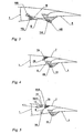
- the advanced wing trailing edge on the wing of an aircraft is in its entirety in FIG. 1 shown schematically.
- the following nomenclature is used to understand the kinematic sketch. Individual kinematic elements are numbered consecutively and the connection joints between two parts are each characterized by the two numbers of the respective elements (eg: element 1 and element 5 are connected by a hinge 15, mutatis mutandis, the other fasteners arise).
- the advanced wing trailing edge comprises a wing 1, arranged at the trailing edge of the wing 1, extending in the spanwise direction, adjustable to different deflections flap 4, which can be effective both as a control valve and as a lift-increasing flap. This is always referred to as "flap" in the following.
- a strict separation between control surface (primary control surface) and high-lift component (secondary control surface) in the conventional sense is no longer appropriate, but both functions can more or less seamlessly merge into each other.
- a sealing flap 5 is pivotally movable and arranged on the underside between the wing 1 and the flap 4 is a ventilation flap 5 also pivotally movable.
- the flap 4 (the reference numerals are in the FIGS. 6a ) to e) omitted for the purpose of clarity, see.
- the reference numerals in FIGS. 1 to 5 adjustable over both positive flap deflections downwards and negative flap deflections upwards.
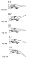
- the flap 4 As a control flap with settings of the flap between negative ( FIG. 6b )) and small positive valve rashes ( FIG. 6d )), the wing profile is closed at the top by a sealing flap 7 and at the bottom by a ventilation flap 5.
- the flap 4 as lift-increasing flap with settings of the flap 4 between small positive flap deflections ( FIG.
- the ventilation flap 5 releases a flow from the underside of the wing 1 to the top of the flap 4 and the sealing flap 7 is removed to release an outflow from the top of the flap 4 by a predetermined gap.
- FIGS. 2 to 5 Since the mechanism of the progressive wing trailing edge in the entire representation is somewhat confusing, is in the FIGS. 2 to 5 a decomposition of the entire mechanism into its four sub-mechanisms.
- the four sub-mechanisms are a flapper guide mechanism, a lower vent flap mechanism, an upper flapper mechanism, and a brake flap mechanism. These individual mechanisms can be found in their entirety in FIG. 1 again.
- the flap guide mechanism which stands for itself in FIG. 2 is shown, it is primarily essentially a simple hinge joint, ie it is only a pivot joint 14 is required, which represents the connection between the wing 1 and the flap 4.
- the wing 1 is from a kinematic perspective, the stationary frame.
- the pivot point 14 is positioned so that for negative flap deflections of the flap 4, the wing profile contour is not left and yet as much area and Völbungsver employedrung for positive flap deflections of the flap 4 is achieved.
- the drive is realized by a linear sliding joint 23, which is rotatably mounted with the wing 1 and the flap 4 at the ends of the respective actuator element.
- the actuator consists of parts 2 and 3 and can be operated either hydraulically (hydraulic actuator) or mechanically (spindle drive).
- the ventilation flap mechanism is basically in FIG. 3 schematically.
- the fixed wing 1 is visible with the fixed bearings 15 and 14.
- the flap 4 and the ventilation flap 5 is connected.
- the function of the ventilation flap 5 has already been mentioned above, but will be briefly explained again for clarity.
- the function of the ventilation flap allows for larger flap angle of the flap 4, see FIG. 6e ), a sufficient flow around the flap 4 with high-energy air, so that more buoyancy occurs and the separation behavior of the flow is delayed.
- the flap 4 is forced mechanically coupled with the ventilation flap 5 or positively coupled, ie there is a clear functional dependence between these two elements.
- the mechanical coupling is realized by a simple rod 6. All bearings are simple hinges in the two-dimensional sketch, in a three-dimensional design, this may be analogous to other joints, for example, ball joints with three rotational degrees of freedom. The mechanical principle remains unchanged in the three-dimensional space, therefore, a two-dimensional representation is sufficient.
- the hinges 15, 14, 56 and 46 are therefore simple hinges in the two-dimensional drawing. Overall, therefore, the forced coupling is realized by the simplest conceivable mechanism (four-bar linkage).
- the lower ventilation flap 5 opens in the direction of the wing contour to the intended opening angle.
- the dimensions of the ventilation flap 5 and the opening angle are determined by the aerodynamic boundary conditions (maximum lift, low air resistance, low noise emissions, etc ).
- the ventilation flap 5 For smaller positive and all negative flap angle of the flap 4, the ventilation flap 5 remains almost in its nominal position.
- the nominal position in this case is characterized by the profile contour in cruising flight. It is thus a "quasi" rest in the range of small positive to large negative flap deflections of the flap 4 by an advantageous technical design of the transmission gear (the aforementioned four-bar linkage) achieved.
- a complete seal the ventilation flap to the flap 4 guaranteed, thereby the profile contour always aerodynamic (low air resistance) and harmful noise sources in the form of edges, profile contour jumps Leewirbel whichen be avoided.
- the sealing flap mechanism is basically in FIG. 4 schematically.
- the stationary wing 1 can be seen with the stationary bearing 14.
- the flap 4 is connected.
- a bearing 79 is only fixed to the wing 1, if the brake flap function of the upper sealing flap 7 is not driven.
- the bearing 79 and another bearing 910 are on a common axis of rotation, so this is a kind of double joint.
- the bearing 79 is stationary to the wing 1.
- the functions of the upper sealing flap 7 will be shown in detail below. Due to the demand to allow negative flap deflections of the flap 4, it is necessary to raise the upper wing contour or the air brakes normally located at this point on commercial aircraft to a collision of the sealing flap 7 (the sealing flap 7 is also the same time the brake flap, see the following) to avoid with the flap 4.
- a mechanical coupling rod 8 connects the sealing flap 7 and the flap 4.
- the brake flap mechanism operates almost completely mechanically decoupled from the flap mechanism, there is only a functional dependence between the absolute brake flap deflection of the upper sealing flap 7 (relative to the stationary wing 1) and the flap deflection angle of the flap 4, this is taken into account by a corresponding regulation in the flight control computer.
- This regulation does not affect the Abdichtklappenmechanismus (except in case of failure), because the aerodynamic gap is abandoned in the brake flap mode with corresponding loss of lift and increase in air resistance.
- the normal brake flap functions can thus be generated unchanged by a further drive (element 10 and element 11), without the above-mentioned mechanism of the lower panel (ventilation flap) 5 and the upper panel (sealing flap) 7 would be impaired in its operation.
- the typical brake flap acts as an air brake, buoyancy regulator, roll control and wing relief.
- FIG. 5 the additional kinematic elements are shown, which also enable the brake flap function for the upper sealing flap 7. Consequently, the upper sealing flap also acts as a brake flap. Furthermore, the brake flap function is actuated by its own drive.
- the actuator device consists of the parts 10 (actuator) and 11 (actuator rod) and can be operated hydraulically (hydraulic actuator) or mechanically (spindle drive).
- the actuator device of the brake flap function moves the element 9 via the bearing 910 to a bearing 19 on a circular path.
- the movement of the element 9 on the circular path has the consequence that the double joint 79 also moves on this circular path.
- the sealing flap 7 (if it is active as a brake flap) thus moves on the coupling of the four-bar linkage 48, 78, 79 and 19.
- the bearing 19 is placed in an advantageous manner so that there is no collision with the wing 1.
- the brake flap mechanism can not be integrated into the kinematic system but can be provided separately, this would be conceivable in the outer wing area as ailerons.
- the aerodynamic flap gap is held exactly by a mechanical positive guidance to the flap 4, there is no complex control loop to keep the flap gap (aerodynamic Air gap tolerances) necessary. Only the actuator for the flap 4 (actuator body 2 and actuator rod 3) accomplishes these functions. For larger positive flap angle of the flap 4 pivots the lower vent flap 5 in the wing profile contour and the advantageous flow around the flap 4 is achieved.
- the upper sealing flap 7 acts from larger flap angles of the flap 4 no longer as a seal, but must keep the aerodynamic Strömungsververgenz and the aerodynamic gap exactly, see FIG. 6e ): TAB 35 °, A / B 0 °).
- both a primary and a secondary flight control can be effected. Ie. high actuating speeds for primary control surfaces can be realized.
- the wing trailing edge according to the invention can act as an adaptive wing, by small positive or negative stationary flap deflections can always be the most economical operating point for the respective altitude (density, temperature, etc ..), The loading state and the airspeed.
- the airfoil contour remains closed (except in the airbrake mode) and the protil shape remains aerodynamically aerodynamically favorable. In conventional secondary high lift systems this was i. d. R. not possible, because negative flap deflections could not be realized.
- the brake flap mode of the upper sealing flap 7, which acts here as a brake flap, is for better understanding in the FIGS. 7a ) to c) in various configurations (TAB -20 °, A / B 40 °, TAB 0 °, A / B 40, TAB 35 °, A / B 40 °).
Landscapes
- Engineering & Computer Science (AREA)
- Aviation & Aerospace Engineering (AREA)
- Air-Flow Control Members (AREA)
- Braking Arrangements (AREA)
- Transmission Devices (AREA)
Description
Die vorliegende Erfindung betrifft eine fortschrittliche Flügelhinterkante am Tragflügel eines Flugzeugs.The present invention relates to an advanced wing trailing edge on the wing of an aircraft.
Die beschriebene Einrichtung wird am sinnvollsten als fortschrittliche Flügelhinterkante (ATECS - Advanced Trailing Edge Control Surfaces) bezeichnet, weil sie durch die vorgesehene Kinematik und neue multifunktionale Steuerflächen ein erheblich erweitertes Einsatzspektrum gegenüber dem mechanischen Grundprinzip einer einfachen Spaltklappe aufweist.The described device is best referred to as Advanced Trailing Edge Control Surfaces (ATECS), because it has a significantly expanded range of applications over the basic mechanical principle of a simple slit flap due to the proposed kinematics and new multifunctional control surfaces.
Im Stand der Technik sind eine große Anzahl von Flügelhinterklappensystemen bekannt, von denen zunächst ein Auszug der für die vorliegende Erfindung bedeutendsten Vertreter erläutert werden sollen. Die primär relevanten Vertreter dieser sind in erster Linie Einfachspaltklappensysteme. Diese Klappensysteme werden sowohl als primäre als auch sekundäre Flugsteuerung bzw. auch als kombinierte Steuerflächen genutzt. Weiterhin lassen sich diese Vertreter als Rollsteuerung, Nicksteuerung und zur Auftriebserhöhung nutzen. Die letzten beiden genannten Patentschriften zeigen exemplarisch Möglichkeiten auf, um einen adaptiven Flügel zu generieren, der nicht nur für einen "optimalen" Arbeitspunkt ausgelegt ist.In the prior art, a large number of wing trailing flap systems are known, of which at first an extract of the representatives of the present invention are to be explained. The primarily relevant representatives of these are primarily single-gap flap systems. These flap systems are used both as primary and secondary flight control or as combined control surfaces. Furthermore, these representatives can be used as roll control, pitch control and lift increase. The last two cited patents show examples of ways to generate an adaptive wing, which is designed not only for an "optimal" operating point.
Im Grunde genommen handelt es sich bei der einfachen Spaltklappe in der Regel um eine einfache Scharnierlagerung, die durch eine Drehachse im Raum definiert ist. Ist die Drehachse weit unter dem Flügelprofil, lassen sich damit vorteilhafte technische Wirkungen erzielen (
- Die Flügelfläche und die Flügelwölbung werden beim Ausfahren der Klappe (positive Klappenausschläge) vergrößert, wodurch der Auftrieb stark zunimmt.
- Die Klappe bzw. die Steuerfläche wird in die energiereiche Luftströmung gefahren, wodurch ebenfalls der Auftrieb zusätzlich gesteigert wird.
- The wing area and the wing arch are enlarged when the flap is extended (positive flap deflections), which greatly increases buoyancy.
- The flap or the control surface is driven into the high-energy air flow, whereby the buoyancy is also increased.
Es entstehen jedoch einige nachteilige technische Wirkungen:
- Negative Klappenausschläge sind in der Regel nicht möglich, weil die Nasenkante der Klappe die Hüllgeometrie des Flügels auf der Profilunterseite verlässt bzw. es kommt zu erheblichen Bauraumkonflikten im Hinterholmbereich des Flügels (abhängig von der Lage des Drehpunktes).
- Es entstehen häufig konvergent/divergente Luftströmungen in der Spaltluftströmung mit dem entsprechenden Auftriebsverlust und einer starken Widerstandserhöhung.
- Es wird eine in der Luftströmung liegende aerodynamische Verkleidung des mechanischen Klappensystems notwendig, dabei entsteht wieder zusätzlicher Luftwiderstand.
- Negative flap deflections are usually not possible because the nose edge of the flap leaves the envelope geometry of the wing on the underside of the profile or there are significant space conflicts in the rear spar area of the wing (depending on the position of the fulcrum).
- There are often convergent / divergent air flows in the split air flow with the corresponding loss of lift and a strong increase in resistance.
- An aerodynamic lining of the mechanical flap system, which is located in the air flow, becomes necessary, resulting in additional air resistance.
Ist die Drehachse nahe an der Nasenkante der Klappe (
- Positive und negative Klappenausschläge lassen sich durch einfachere Konstruktionen umsetzten.
- Dies ist für primäre Steuerflächen entscheidend, weil diese in der Regel in beide Richtungen ausschlagen müssen (Höhen-/Quer-/Seitenruder). Sekundäre Steuerflächen operieren primär als Hochauftriebskomponenten am Flugzeug, diese haben in der Regel nur eine bevorzugte Wirkrichtung.
- Es entsteht jedoch ein entscheidender Nachteil durch diese Lage des Drehpunktes: die energiereiche Luftströmung kann die Klappe nicht mehr umströmen. Die Umströmung der energiereichen Luftströmung auf der Flügelunterseite hat die vorteilhafte technische Wirkung, dass das Ablöseverhalten des gesamten Flügels entscheidend verbessert wird. Dieses Problem wird durch eine unter dem Flügel liegende Belüftungsklappe beseitigt (
US2117607
- Positive and negative flap deflections can be implemented by simpler constructions.
- This is crucial for primary control surfaces because they usually have to deflect in both directions (elevator / aileron / rudder). Secondary control surfaces operate primarily as high-lift components on the aircraft, these usually have only a preferred effective direction.
- However, there is a decisive disadvantage of this position of the fulcrum: the high-energy air flow can no longer flow around the flap. The flow around the high-energy air flow on the wing underside has the advantageous technical effect that the separation behavior of the entire wing is significantly improved. This problem is solved by a ventilation flap under the wing (
US2117607
Die untere Belüftungsklappe der hier genannten Patentschriften ist in der Regel nur für positive Klappenausschläge konzipiert (
Es gibt auch bekannte Klappensysteme (
Ein weiteres bekanntes Klappensystem (
Viele der bekannten Klappensysteme verfügen über relativ komplexe kinematische Systeme, die aus einer hohen Anzahl an Teilen bestehen (
Normale Hochauftriebssysteme sind nur für positive Klappenausschläge ausgelegt, auf ihrer oberen Seite sind die meisten Systeme mit Bremsklappen ausgerüstet. Die Bremsklappen werden meistens über einen eigenen Antrieb angesteuert (
Ein adaptiver Flügel erfordert in der Regel weitere komplexe Systeme, die häufig mit den bestehenden primären und sekundären Steuerflächen kollidieren. Es werden weitere Antriebe, eine hohe Anzahl an Teilen, flexible Strukturen und weitere Regelkreise mit den entsprechen Sensoren notwendig. Exemplarisch seien zwei benannte Systeme zum Verstellen des gesamten Flügelprofils bzw. Profildruckverlaufes genannt (
Ferner beschreibt
Die Aufgabe der vorliegenden Erfindung ist es, eine Flügelhinterkante zu schaffen, bei der sowohl primäre und sekundäre Steuerflächen am Flügel mit weniger mechanischem Aufwand und weniger Gewicht verwirklicht sind.The object of the present invention is to provide a blade trailing edge in which both primary and secondary control surfaces are realized on the wing with less mechanical effort and less weight.
Diese Aufgabe wird durch eine fortschrittliche Flügelhinterkante mit den Merkmalen des Anspruchs 1 gelöst. Vorteilhafte Ausführungen und Weiterbildungen der erfindungsgemäßen Flügelhinterkante sind in den Unteransprüchen angegeben.This object is achieved by an advanced blade trailing edge with the features of
Durch die Erfindung wird eine fortschrittliche Flügelhinterkante am Flügel eines Flugzeugs, mit einem Flügel, einer an der Hinterkante des Flügels angeordneten, in Spannweitenrichtung verlaufenden, auf unterschiedliche Ausschläge einstellbaren Klappe, einer an der Oberseite zwischen dem Flügel und der Klappe angeordneten schwenkbar beweglichen Abdichtklappe und einer an der Unterseite zwischen dem Flügel und der Klappe angeordneten schwenkbar beweglichen Belüftungsklappe geschaffen. Erfindungsgemäß ist es vorgesehen, dass die Klappe sowohl über positive Klappenausschläge nach unten und negative Klappenausschläge nach oben einstellbar ist, wobei für eine Nutzung der Klappe als Steuerklappe mit Einstellungen der Klappe zwischen negativen und kleinen positiven Klappenausschlägen das Flügelprofil an der Oberseite durch die Abdichtklappe und an der Unterseite durch die Belüftungsklappe geschlossen ist und für eine Nutzung der Klappe als auftriebserhöhende Klappe mit Einstellungen der Klappe zwischen kleinen positiven und großen positiven Klappenausschlägen die Belüftungsklappe eine Strömung von der Unterseite des Flügels zur Oberseite der Klappe freigibt und die Abdichtklappe zur Freigabe eines Abstroms von der Oberseite der Klappe um einen vorgegebenen Spalt entfernt wird.The invention provides an advanced wing trailing edge on the wing of an aircraft, having a wing, a spanwise span extending flap adjustable at the trailing edge of the wing, one at the top between arranged pivotally movable sealing flap arranged on the wing and the flap and a pivotally movable ventilation flap arranged on the underside between the wing and the flap. According to the invention it is provided that the flap is adjustable both on positive flap deflections down and negative flap deflections, wherein for use of the flap as a control valve with settings of the flap between negative and small positive flap deflections the wing profile at the top through the Abdichtklappe and the bottom is closed by the ventilation flap and for using the flap as a lift increasing flap with settings of the flap between small positive and large positive flap deflections the vent flap a flow from the underside of the wing to the top of the flap releases and the Abdichtklappe to release an outflow from the top of the flap is removed by a predetermined gap.
Gemäß einer bevorzugten Ausführungsform der erfindungsgemäßen fortschrittlichen Flügelhinterkante ist es vorgesehen, dass die Abdichtklappe zur Nutzung als Bremsklappe mit ihrem hinteren Ende nach oben schwenkbar ist.According to a preferred embodiment of the advanced wing trailing edge according to the invention, it is provided that the sealing flap for use as a brake flap with its rear end is pivotable upwards.
Gemäß einer anderen bevorzugten Ausführungsförm der erfindungsgemäßen fortschrittlichen Flügelhinterkante ist es vorgesehen, dass die Abdichtklappe mit der Klappe zwangsgeführt ist.According to another preferred embodiment of the progressive blade trailing edge according to the invention, it is provided that the sealing flap is forcibly guided with the flap.
Gemäß einer bevorzugten Ausführungsform der Erfindung ist ein Klappenführungsmechanismus vorgesehen, der durch ein zwischen dem Flügel und der Klappe angeordnetes Drehgelenk enthält.According to a preferred embodiment of the invention, a flap guide mechanism is provided, which comprises by a arranged between the wing and the flap pivot.
Vorzugsweise ist der Drehpunkt des Drehgelenks so positioniert, dass für negative Klappenausschläge der Klappe die Flügelprofilkontur nicht verlassen wird und für positive Klappenausschläge der Klappe eine wesentliche Flächen- und Wölbungsvergrößerung erzielt wird.Preferably, the fulcrum of the hinge is positioned so that for negative flap deflections of the flap, the wing profile contour is not left and for positive flap deflections of the flap, a substantial area and Völbungsvergrößerung is achieved.
Gemäß einer bevorzugten Ausführungsform der Erfindung ist es vorgesehen, dass der Antrieb für den Klappenführungsmechanismus durch ein lineares Schubelement gebildet ist, das mit dem Flügel und der Klappe gekoppelt ist.According to a preferred embodiment of the invention, it is provided that the drive for the flap guide mechanism is formed by a linear thrust element, which is coupled to the wing and the flap.
Vorzugsweise enthält das Schubelement einen Aktuator.Preferably, the pusher element includes an actuator.
Der Aktuator kann hydraulisch (Hydraulikaktuator) oder mechanisch (Spindelantrieb) betrieben sein.The actuator can be operated hydraulically (hydraulic actuator) or mechanically (spindle drive).
Gemäß einer bevorzugten Ausführungsform der Erfindung ist es vorgesehen, dass die Klappe ist mit der Belüftungsklappe mechanisch zwangsgeführt bzw. zwangsgekoppelt ist.According to a preferred embodiment of the invention, it is provided that the flap is mechanically positively driven or positively coupled with the ventilation flap.
Gemäß einer bevorzugten Ausführungsform der Erfindung ist ein Belüftungsklappenmechanismus vorgesehen, bei dem die Belüftungsklappe über ein an ortsfesten Lagern und gelagertes, zwei Hebel enthaltendes Hebelwerk an den Flügel angebunden ist.According to a preferred embodiment of the invention, a ventilation flap mechanism is provided in which the ventilation flap is connected to the wing by means of a stationary bearing and a bearing lever mechanism containing two levers.
Gemäß einer bevorzugten Ausführungsform der Erfindung ist ein Abdichtklappenmechanismus vorgesehen, bei dem die Abdichtklappe mit der Klappe zwangsgeführt ist.According to a preferred embodiment of the invention, a sealing flap mechanism is provided in which the sealing flap is positively guided with the flap.
Vorzugsweise ist bei dem Abdichtklappenmechanismus die Abdichtklappe durch ein über ein nahe dem ortsfesten Lager an einem zweiten Lager mit der Klappe und nahe einem vierten Lager über ein drittes Lager mit der Abdichtklappe gekoppeltes Hebelwerk durch die Klappe zwangsgeführt.Preferably, in the sealing flap mechanism, the sealing flap is positively urged through the flap by a lever mechanism coupled to the flap via a proximate bearing at a second bearing to the flap and proximate to a fourth bearing via a third bearing.
Vorzugsweise bildet das den Kopplungsstab enthaltende, die Abdichtklappe mit der Klappe verbindende Hebelwerk ein Gelenkviereck.The lever mechanism containing the coupling rod and connecting the sealing flap to the flap preferably forms a four-bar linkage.
Gemäß einer bevorzugten Ausführungsform der Erfindung ist es vorgesehen, dass, dass das vierte Lager bei Bewegung der Abdichtklappe im Sinne einer Bremsklappenfunktion mitgenommen wird.According to a preferred embodiment of the invention, it is provided that the fourth bearing is entrained upon movement of the sealing flap in the sense of a brake flap function.
Gemäß noch einer bevorzugten Ausführungsform der Erfindung ist ein weiteres Lager an der oberen Abdichtungsklappe vorgesehen, mit welchem ein Aktuator zur Betätigung der Abdichtklappe im Sinne einer Bremsklappenfunktion gekoppelt ist.According to yet a preferred embodiment of the invention, a further bearing is provided on the upper sealing flap, with which an actuator for actuating the sealing flap is coupled in the sense of a brake flap function.
Vorzugsweise ist das weitere Lager auf einer gemeinsamen Drehachse mit dem vierten Lager angeordnet.Preferably, the further bearing is arranged on a common axis of rotation with the fourth bearing.
Insbesondere ist der Abdichtklappenmechanismus so ausgebildet, dass für kleine positive Klappenwinkel bis hin zu allen negativen Klappenwinkeln der Klappe eine Kollision zwischen der Klappe und der Abdichtklappe vermieden und die Abdichtklappe im gesamten gerade erwähnten Bereich gegen die Klappe abgedichtet ist.In particular, the sealing flap mechanism is configured to avoid collision between the flap and the sealing flap for small positive flap angles up to all negative flap angles of the flap and to seal the sealing flap against the flap throughout the range just mentioned.
Gemäß einer bevorzugten Ausführungsform der Erfindung ist es vorgesehen, dass für größere positive Klappenausschläge der Klappe, wo die Klappe als auftriebserhöhende Komponente wirksam ist, die obere Abdichtklappe im Sinne einer Erzeugung eines konvergenten aerodynamischen Spalts durch Drehung um das vierte Lager nach unten abgesenkt wird.According to a preferred embodiment of the invention, it is provided that for larger positive flap deflections of the flap, where the flap is effective as a buoyancy enhancing component, the upper sealing flap is lowered in the sense of creating a convergent aerodynamic gap by rotation about the fourth bearing.
Vorzugsweise wird eine funktionale Abhängigkeit zwischen dem absoluten Bremsklappenausschlag der oberen Abdichtklappe (bezogen auf den ortsfesten Flügel 1) und dem Klappenausschlagwinkel der Klappe durch eine entsprechende Regelung im Flugsteuerungscomputer vorgenommen.Preferably, a functional relationship between the absolute flap angle of the upper sealing flap (relative to the fixed wing 1) and the flap angle of the flap is made by a corresponding regulation in the flight control computer.
Gemäß einer bevorzugten Ausführungsform der Erfindung ist es vorgesehen, dass die für die Bremsklappenfunktion vorgesehene Aktuatoreinrichtung das Element über das weitere Lager um ein Lager auf einer Kreisbahn bewegt, wodurch das durch das vierte Gelenk und das weitere Gelenk gebildete Doppelgelenk ebenfalls sich auf dieser Kreisbahn bewegt.According to a preferred embodiment of the invention, it is provided that the actuator device provided for the brake flap function moves the element via the further bearing about a bearing on a circular path, whereby the double joint formed by the fourth joint and the further joint also moves on this circular path.
Vorzugsweise ist der Bremsklappenmechanismus weitgehend vom oberen Abdichtungsmechanismus entkoppelt.Preferably, the brake flap mechanism is largely decoupled from the upper sealing mechanism.
Der Bremsklappenmechanismus kann auch nicht in das kinematische System integriert sondern separat vorgesehen sein.The brake flap mechanism can not be integrated into the kinematic system but can be provided separately.
Gemäß einer bevorzugten Ausführungsform der Erfindung ist es vorgesehen, dass alle Lager einfache Drehgelenke sind.According to a preferred embodiment of the invention, it is provided that all bearings are simple hinges.
Gemäß einer anderen bevorzugten Ausführungsform der Erfindung ist es vorgesehen, dass die Konstruktion im wesentlichen nur aus Stäben und Fachwerken besteht.According to another preferred embodiment of the invention, it is provided that the construction consists essentially of rods and trusses.
Gemäß einer bevorzugten Ausführungsform der Erfindung ist Kinematik in einer dreidimensionalen Ausführung für eine zylindrische Bewegung der Klappe vorgesehen.According to a preferred embodiment of the invention kinematics is provided in a three-dimensional design for a cylindrical movement of the flap.
Gemäß einer anderen bevorzugten Ausführungsform der Erfindung ist die Kinematik in einer dreidimensionalen Ausführung für eine konische Bewegung der Klappe vorgesehen.According to another preferred embodiment of the invention, the kinematics is provided in a three-dimensional design for a conical movement of the flap.
Die fortschrittliche Flügelhinterkante kann als primäre Steuerfläche dienen.The advanced blade trailing edge can serve as the primary control surface.
Die fortschrittliche Flügelhinterkante kann als sekundäre Steuerfläche dienen.The advanced blade trailing edge can serve as a secondary control surface.
Die fortschrittliche Flügelhinterkante kann als adaptive Flügelkomponente dienen.The advanced wing trailing edge can serve as an adaptive wing component.
Die erfindungsgemäße fortschrittliche Flügelhinterkante ist in mit Vorteil für eine Verwendung an der Flügelhinterkante in modernen Verkehrsflugzeugen und Transportflugzeugen mit einem hohem Abfluggewicht vorgesehen.The advanced wing trailing edge of the present invention is advantageously provided for use at the trailing edge of trailing wings in modern commercial and high takeoff weight transport aircraft.
Die erfindungsgemäße fortschrittliche Flügelhinterkante zeichnet sich vorteilhafterweise durch ein geringes Gewicht, durch eine hohe Zuverlässigkeit, durch eine geringe Anzahl an Teilen und durch eine strukturell einfache Konstruktion aus. Die komplexen Forderungen an ein fortschrittliches Flügelhinterkantenkonzept wurden bestmöglich verwirklicht. Des Weiteren entfallen die ganzen Tragstrukturen und das kinematischen System eines konventionellen Hochauftriebssystems. Die aerodynamische Verkleidung ist bei der fortschrittlichen Flügelhinterkante erheblich kleiner, wodurch sich für den gesamten Reiseflug ein wirtschaftlicher Vorteil einstellen wird (geringer Widerstand, geringe Treibstoffkosten).The advanced wing trailing edge of the present invention is advantageously characterized by low weight, high reliability, a small number of parts, and a structurally simple construction. The complex demands on an advanced wing trailing edge concept were realized in the best possible way. Furthermore, the entire supporting structures and the kinematic system of a conventional high-lift system are eliminated. The aerodynamic fairing is significantly smaller with the advanced wing trailing edge, which will provide an overall economic advantage for the entire cruise (low drag, low fuel cost).
Im Folgenden soll ein Ausführungsbeispiel der erfindungsgemäßen fortschrittlichen Flügelhinterkante unter Bezugnahme auf die Zeichnung im Einzelnen beschrieben werden.In the following, an embodiment of the advanced wing trailing edge according to the invention will be described in detail with reference to the drawing.
- Figur 1FIG. 1
- eine schematisierte Gesamtdarstellung einer fortschrittlichen Flügelhinterkante gemäß einem Ausführungsbeispiel der Erfindung in einer seitlichen Schnittansicht;a schematic overall view of an advanced wing trailing edge according to an embodiment of the invention in a side sectional view;
- Figur 2FIG. 2
- eine schematisierte Darstellung eines in der fortschrittlichen Flügelhinterkante enthaltenen Klappenführungsmechanismus gemäß dem Ausführungsbeispiel der Erfindung in einer seitlichen Schnittansicht;a schematic representation of a contained in the advanced wing trailing edge flap guide mechanism according to the embodiment of the invention in a sectional side view;
- Figur 3FIG. 3
- eine schematisierte Darstellung eines in der fortschrittlichen Flügelhinterkante enthaltenen unteren Belüftungsklappenmechanismus gemäß dem Ausführungsbeispiel der Erfindung in einer seitlichen Schnittansicht;a schematic representation of a lower vent flap mechanism included in the progressive wing trailing edge according to the embodiment of the invention in a sectional side view;
- Figur 4FIG. 4
- eine schematisierte Darstellung eines in der fortschrittlichen Flügelhinterkante enthaltenen oberen Abdichtklappenmechanismus gemäß dem Ausführungsbeispiel der Erfindung in einer seitlichen Schnittansicht;a schematic representation of a contained in the progressive blade trailing edge upper Abdichtklappenmechanismus according to the embodiment of the invention in a sectional side view;
- Figur 5FIG. 5
- eine schematisierte Darstellung eines in der fortschrittlichen Flügelhinterkante enthaltenen Bremsklappenmechanismus gemäß dem Ausführungsbeispiel der Erfindung in einer seitlichen Schnittansicht;a schematic representation of a brake flap mechanism contained in the advanced wing trailing edge according to the embodiment of the invention in a sectional side view;
- Figuren 6a) bis e)FIGS. 6a) to e)
- jeweilige schematisierte Darstellungen der erfindungsgemäßen Flügelhinterkante mit unterschiedlichen Einstellungen der Klappe; undrespective schematic representations of the wing trailing edge according to the invention with different settings of the flap; and
- Figur 7a) bis c)FIGS. 7a) to c)
- jeweilige schematisierte Darstellungen der erfindungsgemäßen Flügelhinterkante mit unterschiedlichen Einstellungen der oberen Abdichtklappe in ihrer Funktion als Bremsklappe.respective schematic representations of the wing trailing edge according to the invention with different settings of the upper sealing flap in its function as a brake flap.
Die fortschrittliche Flügelhinterkante am Flügel eines Flugzeugs ist in ihrer Gesamtheit in
Wie die
Da der Mechanismus der fortschrittlichen Flügelhinterkante in der gesamten Darstellung etwas unübersichtlich ist, wird in den
Beim Klappenführungsmechanismus, der für sich in
Der Antrieb wird durch ein lineares Schubgelenk 23, das mit dem Flügel 1 und der Klappe 4 drehbar an den Enden des jeweiligen Aktuatorelements gelagert ist, realisiert. Der Aktuator besteht aus den Teilen 2 und 3 und kann einerseits hydraulisch (Hydraulikaktuator) oder mechanisch (Spindelantrieb) betrieben werden.The drive is realized by a linear sliding joint 23, which is rotatably mounted with the
Der Belüftungsklappenmechanismus ist prinzipiell in
Die Klappe 4 ist mit der Belüftungsklappe 5 mechanisch zwangsgeführt bzw. zwangsgekoppelt, d.h. es gibt eine eindeutige funktionelle Abhängigkeit zwischen diesen beiden Elementen. Die mechanische Kopplung wird durch einen einfachen Stab 6 realisiert. Alle Lager sind einfache Drehgelenke in der zwei dimensionalen Skizze, in einer dreidimensionalen Ausführung kann es sich hierbei sinngemäß um andere Gelenke handeln z.B. Kugelgelenke mit drei Rotationsfreiheitsgraden. Das mechanische Prinzip bleibt im dreidimensionalen Raum unverändert erhalten, daher reicht eine zweidimensionale Darstellung. Die Drehgelenke 15, 14, 56 und 46 sind also einfache Drehgelenke in der zweidimensionalen Zeichnung. Insgesamt wird also die Zwangskopplung durch den einfachst denkbaren Mechanismus (Gelenkviereck) realisiert.The
Für größere positive Klappenwinkel der Klappe 4, vergleiche
Für kleinere positive und alle negativen Klappenwinkel der Klappe 4 bleibt die Belüftungsklappe 5 nahezu in ihrer nominalen Lage. Die nominale Lage ist in diesem Fall durch die Profilkontur im Reiseflug charakterisiert. Es wird also eine "quasi" Rast im Bereich von kleinen positiven bis in großen negativen Klappenausschlägen der Klappe 4 durch eine vorteilhafte technische Auslegung des Übertragungsgetriebes (das erwähnte Gelenkviereck) erzielt. Weiterhin ist im Bereich von kleinen positiven bis in großen negativen Klappenausschlägen der Klappe 4 eine komplette Dichtung der Belüftungsklappe zur Klappe 4, gewährleistet, dadurch bleibt die Profilkontur immer strömungsgünstig (geringer Luftwiderstand) und schädliche Lärmquellen in Form von Kanten, Profilkontursprüngen, Leewirbelgebieten werden vermieden.For smaller positive and all negative flap angle of the
Der Abdichtungsklappenmechanismus ist prinzipiell in
Die Funktionen der oberen Abdichtungsklappe 7 sollen nachfolgend im Einzelnen dargestellt werden. Durch die Forderung negative Klappenausschläge der Klappe 4 zu ermöglichen, wird es notwendig die obere Flügelkontur bzw. die normalerweise an dieser Stelle befindlichen Bremsklappen an Verkehrsflugzeugen anzuheben, um eine Kollision der Abdichtklappe 7 (die Abdichtklappe 7 ist auch gleichzeitig die Bremsklappe, siehe nachfolgende Ausführungen) mit der Klappe 4 zu vermeiden.The functions of the
Für kleine positive Klappenwinkel, vergleiche
Für größere positive Klappenausschläge der Klappe 4, vergleiche
Für eine solche Zwangsführung wird wieder die einfachste mechanische Lösung favorisiert, daher werden alle genannten Forderungen durch eine vorteilhafte Auslegung des oben genannten Gelenkvierecks (Lager: 79, 78, 48, 14) umgesetzt. Ein mechanischer Kopplungsstab 8 verbindet die Abdichtklappe 7 und die Klappe 4.For such a positive guidance, the simplest mechanical solution is favored again, therefore, all the above requirements are implemented by an advantageous design of the above four-bar linkage (bearings: 79, 78, 48, 14). A
Der Bremsklappenmechanismus arbeitet nahezu komplett mechanisch entkoppelt vom Klappenmechanismus, es besteht lediglich eine funktionale Abhängigkeit zwischen dem absoluten Bremsklappenausschlag der oberen Abdichtklappe 7 (bezogen auf den ortsfesten Flügel 1) und dem Klappenausschlagwinkel der Klappe 4, dies wird durch eine entsprechende Regelung im Flugsteuerungscomputer berücksichtigt. Diese Regelung tangiert nicht den Abdichtklappenmechanismus (außer im Fehlerfall), weil im Bremsklappenmodus das aerodynamische Spaltmaß aufgegeben wird mit entsprechendem Auftriebsverlust und Erhöhung des Luftwiderstandes.The brake flap mechanism operates almost completely mechanically decoupled from the flap mechanism, there is only a functional dependence between the absolute brake flap deflection of the upper sealing flap 7 (relative to the stationary wing 1) and the flap deflection angle of the
Die normalen Bremsklappenfunktionen können somit unverändert durch einen weiteren Antrieb (Element 10 und Element 11) generiert werden, ohne das der zuvor erwähnte Mechanismus des unteren Paneels (Belüftungsklappe) 5 und des oberen Paneels (Abdichtklappe) 7 in seiner Funktionsweise beeinträchtigt wäre. Die typische Bremsklappe wirkt unter anderem als Luftbremse, als Auftriebsvemichter, als Rollsteuerung und als Flügelentlastung.The normal brake flap functions can thus be generated unchanged by a further drive (
In
Bei Bedarf kann der Bremsklappenmechanismus auch nicht in das kinematische System integriert sondern separat vorgesehen werden, dies wäre im äußeren Flügelbereich als Querruder denkbar.If necessary, the brake flap mechanism can not be integrated into the kinematic system but can be provided separately, this would be conceivable in the outer wing area as ailerons.
Für negative Klappenausschläge und kleine positive Klappenausschläge der Klappe 4 ist die Flügelprofilform komplett abgedichtet (durch die untere Belüftungsklappe 5 und die obere Abdichtungsklappe 7 und strömungsgünstig, dadurch ergibt sich ein günstiger Widerstandsbeiwert und es werden keine Wirbel generiert, die auch zur Lärmemission beitragen (siehe
Der aerodynamischer Klappenspalt wird durch eine mechanische Zwangsführung zur Klappe 4 exakt gehalten, es wird kein komplexer Regelkreis zum Einhalten des Klappenspalts (aerodynamischen Luftspalttoleranzen) notwendig. Allein der Aktuator für die Klappe 4 ( Aktuatorkörper 2 und Aktuatorstange 3) bewerkstelligt diese Funktionen. Für größere positive Klappenwinkel der Klappe 4 schwenkt die untere Belüftungsklappe 5 in die Flügelprofilkontur und die vorteilhafte Umströmung der Klappe 4 wird erzielt. Die obere Abdichtungsklappe 7 agiert ab größeren Klappenwinkeln der Klappe 4 nicht mehr als Dichtung, sondern muss die aerodynamische Strömungskonvergenz und das aerodynamische Spaltmaß exakt halten, siehe
Die Bereiche, wo die untere Belüftungsklappe 5 von den Kopplungsstäben 6 und 8 durchdrungen wird, bzw. wo Tragstrukturen zum Flügel 1 verlaufen, werden aerodynamische Verkleidungen (Fairings) angebracht.The areas where the
Mit der erfindungsgemäßen Flügelhinterkante lassen sich sowohl eine primäre als auch eine sekundäre Flugsteuerung bewirken. D. h. hohe Stellgeschwindigkeiten für primäre Steuerflächen lassen sich verwirklichen.With the wing trailing edge according to the invention, both a primary and a secondary flight control can be effected. Ie. high actuating speeds for primary control surfaces can be realized.
Die erfindungsgemäße Flügelhinterkante kann als adaptiver Flügel fungieren, durch kleine positive bzw. negative stationäre Klappenausschläge kann immer der wirtschaftlich günstigste Betriebspunkt für die jeweilige Flughöhe (Dichte, Temperatur, usw....), den Beladungszustand und der Fluggeschwindigkeit eingestellt werden. Für kleine positive Klappenausschläge und für alle negativen Klappenausschläge bleibt die Flügelprofilkontur geschlossen (außer im Bremsklappenmodus) und die Protilform bleibt aerodynamisch strömungsgünstig. Bei herkömmlich sekundären Hochauftriebssystemen war dies i. d. R. nicht möglich, weil sich negative Klappenausschläge nicht realisieren ließen.The wing trailing edge according to the invention can act as an adaptive wing, by small positive or negative stationary flap deflections can always be the most economical operating point for the respective altitude (density, temperature, etc ..), The loading state and the airspeed. For small positive flap deflections and for all negative flap deflections, the airfoil contour remains closed (except in the airbrake mode) and the protil shape remains aerodynamically aerodynamically favorable. In conventional secondary high lift systems this was i. d. R. not possible, because negative flap deflections could not be realized.
Der Bremsklappenmodus der oberen Abdichtklappe 7, die hier als Bremsklappe wirkt, ist zum besseren Verständnis in den
Ergänzend ist darauf hinzuweisen, dass "umfassend" keine anderen Elemente oder Schritte ausschließt und "eine" oder "ein" keine Vielzahl ausschließt. Ferner sei darauf hingewiesen, dass Merkmale oder Schritte, die mit Verweis auf eines der obigen Ausführungsbeispiele beschrieben worden sind, auch in Kombination mit anderen Merkmalen oder Schritten anderer oben beschriebener Ausführungsbeispiele verwendet werden können. Bezugszeichen in den Ansprüchen sind nicht als Einschränkung anzusehen.In addition, it should be noted that "encompassing" does not exclude other elements or steps, and "a" or "an" does not exclude a multitude. It should also be appreciated that features or steps described with reference to any of the above embodiments may also be used in combination with other features or steps of other embodiments described above. Reference signs in the claims are not to be considered as limiting.
- 11
- Flügelwing
- 22
- Aktuatorkörperactuator body
- 33
- Aktuatorstangeactuator rod
- 44
- Klappeflap
- 55
- Belüftungsklappeventilation flap
- 66
- StabRod
- 77
- Abdichtklappesealing flap
- 88th
- Verbindungsstangeconnecting rod
- 99
- Verbindungsstangeconnecting rod
- 1010
- Aktuatorstangeactuator rod
- 1111
- Aktuatorkörperactuator body
- 1212
- ortsfestes Lagerstationary warehouse
- 1414
- ortsfestes Lagerstationary warehouse
- 1515
- ortsfestes Lagerstationary warehouse
- 1919
- Lagercamp
- 2323
- Verbindungsstangeconnecting rod
- 3434
- Lagercamp
- 4646
- Drehgelenkswivel
- 4848
- zweites Lagersecond camp
- 5656
- Drehgelenkswivel
- 7878
- drittes Lagerthird camp
- 7979
- viertes Lagerfourth camp
- 111111
- ortsfestes Lager, Drehgelenkfixed bearing, swivel joint
- 910910
- Lagercamp
- 10111011
- Verbindungsstangeconnecting rod
Claims (30)
- An advanced trailing edge on the wing of an aircraft, with a wing (1), a flap (4) arranged on the trailing edge of the wing, extending in the wingspan direction and being adjustable to different deflections, a pivoted movable sealing flap (7) that is arranged on the upper side between the wing (1) and the flap (4), and a pivoted movable ventilation flap (5) that is arranged on the underside between the wing (1) and the flap (4), wherein the flap (4) can be adjusted downward through positive flap deflections as well as upward through negative flap deflections, characterized in that the wing profile is closed on the upper side by the sealing flap (7) and on the underside by the ventilation flap (5) for use of the flap (4) as a control flap with adjustments of the flap between negative and low positive flap deflections, and the ventilation flap (5) releases an air flow from the underside of the wing (1) to the upper side of the flap (4) for use of the flap (4) for increasing the lift with adjustments of the flap (4) between low positive and high positive flap deflections and the sealing flap (7) is removed to form a predetermined gap in order to release an outflow of air from the upper side of the flap (4).
- The advanced trailing edge of claim 1, characterized in that the rear end of the sealing flap (7) can be pivoted upward for use as a brake flap.
- The advanced trailing edge of claim 1 or 2, characterized in that the sealing flap (7) is forced driven by the flap (4).
- The advanced trailing edge of claim 1, 2 or 3 characterized, in that a flap guide mechanism is provided, that contains a hinge (14) arranged between the wing (1) and the flap (4).
- The advanced trailing edge of claim 1, 2, 3 or 4, characterized in that the pivotal point of the hinge (14) is positioned such that the flap does not diverge from the wing profile contour for negative flap deflections of the flap (4) and a significant surface increase and curvature increase is achieved in positive flap deflections of the flap (4).
- The advanced trailing edge of claim 1 to 5, characterized in that the drive for the flap guide mechanism consists of a linear feed element (23) that is coupled to the wing (1) and to the flap (4).
- The advanced trailing edge of claim 6, wherein the feed element (23) comprises an actuator (2, 3).
- The advanced trailing edge of claim 7, characterized in that in the actuator (2, 3) is operated hydraulically (hydraulic actuator) or mechanically (spindle drive).
- The advanced trailing edge of claim 1 to 8, characterized in that the flap (4) is mechanically forced-driven, or forced-coupled with the ventilation flap (5).
- The advanced trailing edge of claim 9, characterized in that a ventilation flap mechanism is provided, in which the ventilation flap (5) is connected to the wing (1) by a lever mechanism that is supported on stationary bearings (15) and (14) and contains two levers (rods 5, 6).
- The advanced trailing edge of claim 1 to 10, characterized in that a sealing flap mechanism is provided, in which the sealing flap (7) is forced driven by the flap.
- The advanced trailing edge of claim 11, characterized in that the sealing flap (7) of the sealing flap mechanism is forced driven by the flap (4) by a lever mechanism that is coupled to the flap (4) at a second bearing (48) near the stationary bearing (14) and to the sealing flap (7) by a third bearing (78) near a fourth bearing (79).
- The advanced trailing edge of claim 12, characterized in that the lever mechanism that connects the sealing flap (7) to the flap (4) and contains the coupling rod (8) forms a four-bar mechanism (bearings 79, 78, 48, 14).
- The advanced trailing edge of claim 12 and 13, characterized in that the fourth bearing (79) participates in a movement of the sealing flap (7) in the sense of a brake flap function.
- The advanced trailing edge of claim 13 or 14, characterized in that another bearing (910) is provided on the upper sealing flap (7), to which an actuator (10, 11) is coupled in order to actuate the sealing flap (7) in the sense of a brake flap function.
- The advanced trailing edge of claim 15, characterized in that the additional bearing (910) is arranged on a common pivoting axis with the fourth bearing (79).
- The advanced trailing edge of claim 11 to 16, characterized in that the sealing flap mechanism is formed such that a collision between the flap (4) and the sealing flap (7) is prevented between low positive flap angles and all negative flap angles of the flap (4) and the sealing flap (7) is sealed relative to the flap (4) in the entire aforementioned range.
- The advanced trailing edge of claim 17, characterized in that the upper sealing flap (7) is lowered downward in order to produce a convergent aerodynamic gap by rotation about the fourth bearing (79) at major positive flap deflections of the flap (4), in which the flap (4) acts as a lift-increasing component.
- The advanced trailing edge of one of the claims 11 to 18, characterized in that a functional dependence between the absolute brake flap deflection of the upper sealing flap (7) (referred to the stationary wing (1)) and the flap deflection angle of the flap (4) is realized by a corresponding control in the flight control computer.
- The advanced trailing edge of one of the claims 11 to 19, characterized in that the actuator device (10, 11) provided for the brake flap function moves the element (9) along a circular path about a bearing (19) by the additional bearing (910) such that the double hinge formed by the fourth hinge (79) and the additional hinge (910) also moves along this circular path.
- The advanced trailing edge of one of the claims 11 to 20, characterized in that the brake flap mechanism preferably is largely decoupled from the upper sealing mechanism.
- The advanced trailing edge of one of the claims 11 to 14, characterized in that the brake flap mechanism is not integrated into the kinematic system but provided separately.
- The advanced trailing edge of one of the claims 1 to claim 22, characterized in that all bearings are simple hinges.
- The advanced trailing edge of one of the precedent claims, characterized in that the construction essentially consists of rods and frameworks only.
- The advanced trailing edge of one of claims 1 to 24, characterized in that the kinematics designed three-dimensionally are provided for a cylindrical movement of the flap (4).
- The advanced trailing edge of one of the claim 1 to 24, characterized in that the kinematics designed three-dimensionally are provided for a conical movement of the flap (4).
- The advanced trailing edge of one of the claims 1 to 26, characterized in that the advanced trailing edge serves as primary control surface.
- The advanced trailing edge of one of the claims 1 to 26, characterized in that the advanced trailing edge serves as secondary control surface.
- The advanced trailing edge of one of the precedent claims, characterized in that the advanced trailing edge serves as adaptive wing component.
- The advanced trailing edge of one of the precedent claims, characterized in that the advanced trailing edge is used on the trailing wing edge of commercial aircraft and transport aircraft with a high take-off weight.
Applications Claiming Priority (2)
| Application Number | Priority Date | Filing Date | Title |
|---|---|---|---|
| DE102005045759A DE102005045759A1 (en) | 2005-09-23 | 2005-09-23 | Progressive aerofoil trailing edge for aircraft has flap, which can be adjusted both downward and upward by positive and by negative flap deflections respectively whereby aerofoil profile is closed on top side by sealing flap |
| PCT/EP2006/009067 WO2007054150A1 (en) | 2005-09-23 | 2006-09-18 | Advanced trailing edge control surface on the wing of an aircraft |
Publications (2)
| Publication Number | Publication Date |
|---|---|
| EP1926660A1 EP1926660A1 (en) | 2008-06-04 |
| EP1926660B1 true EP1926660B1 (en) | 2009-12-30 |
Family
ID=37561117
Family Applications (1)
| Application Number | Title | Priority Date | Filing Date |
|---|---|---|---|
| EP06805758A Expired - Fee Related EP1926660B1 (en) | 2005-09-23 | 2006-09-18 | Advanced trailing edge control surface on the wing of an aircraft |
Country Status (9)
| Country | Link |
|---|---|
| US (1) | US8336829B2 (en) |
| EP (1) | EP1926660B1 (en) |
| JP (1) | JP2009508737A (en) |
| CN (1) | CN100542889C (en) |
| BR (1) | BRPI0616191A2 (en) |
| CA (1) | CA2622320A1 (en) |
| DE (2) | DE102005045759A1 (en) |
| RU (1) | RU2405715C2 (en) |
| WO (1) | WO2007054150A1 (en) |
Cited By (1)
| Publication number | Priority date | Publication date | Assignee | Title |
|---|---|---|---|---|
| EP1787905A2 (en) | 2005-11-21 | 2007-05-23 | The Boeing Company | Aircraft trailing edge devices, including devices having forwardly positioned hinge lines, and associated methods |
Families Citing this family (19)
| Publication number | Priority date | Publication date | Assignee | Title |
|---|---|---|---|---|
| DE102009011662A1 (en) * | 2009-03-04 | 2010-09-09 | Airbus Deutschland Gmbh | Wing of an aircraft and arrangement of a wing with a device for influencing the flow |
| DE102009060325A1 (en) | 2009-12-23 | 2011-06-30 | Airbus Operations GmbH, 21129 | High-lift system for an aircraft |
| DE102010010577A1 (en) * | 2010-03-08 | 2011-09-08 | Airbus Operations Gmbh | High-lift system for an aircraft |
| EP2514667B1 (en) * | 2011-04-18 | 2015-06-10 | Claverham Limited | Active gurney flap |
| DE102011018907A1 (en) * | 2011-04-28 | 2012-10-31 | Airbus Operations Gmbh | High lift component for an aircraft, high lift system, method for influencing the high lift characteristics of an aircraft and aircraft |
| CN102787772A (en) * | 2011-08-05 | 2012-11-21 | 薛广振 | Space hinge |
| GB201117340D0 (en) | 2011-10-07 | 2011-11-23 | Airbus Uk Ltd | Flat support |
| DE102012111690A1 (en) * | 2012-11-30 | 2014-06-05 | Airbus Operations Gmbh | A variable-shape aerodynamic fairing body for a flap adjustment mechanism of an aircraft |
| US9550559B1 (en) | 2013-07-08 | 2017-01-24 | The Boeing Company | Aircraft wing assemblies |
| FR3011226B1 (en) * | 2013-09-30 | 2017-05-19 | Airbus Operations Sas | HYPERSUSTENTER LEAK DEPENDENT SHUTTER SYSTEM FOR AN AIRCRAFT SAIL. |
| US9038943B1 (en) * | 2014-04-11 | 2015-05-26 | Ralph F. Morris | Safety aileron system |
| FR3028084B1 (en) * | 2014-11-03 | 2020-12-25 | Sagem Defense Securite | METHOD AND DEVICE FOR GUIDING AN AIRCRAFT |
| US11046425B2 (en) * | 2016-05-20 | 2021-06-29 | Bombardier Inc. | Apparatus and methods for actuating a double-slotted flap using a slave screw |
| US11192625B2 (en) * | 2016-06-17 | 2021-12-07 | Bombardier Inc. | Panels for obstructing air flow through apertures in an aircraft wing |
| US20180099736A1 (en) * | 2016-10-12 | 2018-04-12 | The Boeing Company | Aircraft wings, aircraft, and related methods |
| JP6955393B2 (en) * | 2017-08-21 | 2021-10-27 | 株式会社東芝 | Sheet processing device and control method |
| CN108408026A (en) * | 2018-05-16 | 2018-08-17 | 江西冠通用飞机有限公司 | A kind of general-purpose aircraft tailspin changes device |
| CN109606640A (en) * | 2018-11-07 | 2019-04-12 | 中国航空工业集团公司西安飞机设计研究所 | A kind of aircraft flexible trailing edge upper limb surface seal structure |
| CN114379767B (en) * | 2022-01-14 | 2023-11-10 | 成都飞机工业(集团)有限责任公司 | Double-hinge mechanism based on middle-large unmanned aerial vehicle wing and angle indication method |
Family Cites Families (37)
| Publication number | Priority date | Publication date | Assignee | Title |
|---|---|---|---|---|
| GB176909A (en) | 1920-12-21 | 1922-03-21 | Frederick Handley Page | Improvements in means for balancing and regulating the lift of aircraft |
| US2169416A (en) | 1936-06-12 | 1939-08-15 | United Aircraft Corp | Slotted deflector flap |
| US2117607A (en) * | 1936-08-04 | 1938-05-17 | United Aircraft Corp | Slotted deflector flap |
| FR846337A (en) | 1938-05-17 | 1939-09-14 | High lift device | |
| US2276522A (en) | 1938-07-23 | 1942-03-17 | Dornier Werke Gmbh | Wing system for airplanes |
| US2261363A (en) * | 1939-04-29 | 1941-11-04 | United Aireraft Corp | Spoiler |
| US2635837A (en) * | 1945-04-09 | 1953-04-21 | Charles H Grant | Aircraft aileron control |
| US2772058A (en) * | 1951-05-10 | 1956-11-27 | Charles H Grant | Aircraft wing with means to increase lift through control of air flow |
| US2836380A (en) | 1955-04-25 | 1958-05-27 | Boeing Co | Airplane wing with slotted flap, cove lip door, and spoiler |
| US2920844A (en) * | 1957-04-12 | 1960-01-12 | North American Aviation Inc | Aircraft boundary-layer control system |
| DE1506615A1 (en) | 1967-06-12 | 1969-08-28 | Ver Flugtechnische Werke | Control flap training and arrangement on a profile of an aircraft |
| US3583660A (en) * | 1969-08-18 | 1971-06-08 | Lockheed Aircraft Corp | Lift and control augmenter for airfoils |
| DE1943680C2 (en) * | 1969-08-28 | 1982-06-24 | Vereinigte Flugtechnische Werke Gmbh, 2800 Bremen | Control flap arrangement |
| US3767140A (en) * | 1971-11-03 | 1973-10-23 | Mc Donnell Douglas Corp | Airplane flaps |
| US3921942A (en) * | 1974-07-01 | 1975-11-25 | Gen Dynamics Corp | Rudder boundary layer control device |
| US3874617A (en) * | 1974-07-17 | 1975-04-01 | Mc Donnell Douglas Corp | Stol flaps |
| US4015787A (en) * | 1975-11-17 | 1977-04-05 | Fairchild Industries Inc. | Aircraft wing |
| US4120470A (en) * | 1976-09-28 | 1978-10-17 | The Boeing Company | Efficient trailing edge system for an aircraft wing |
| DE2725632C2 (en) | 1977-06-07 | 1982-11-11 | Messerschmitt-Bölkow-Blohm GmbH, 8000 München | Ailerons and flap drives for an aircraft |
| US4395008A (en) * | 1980-01-22 | 1983-07-26 | British Aerospace Public Limited Company | Aircraft wing and flap arrangement |
| JPS6047156B2 (en) | 1981-05-27 | 1985-10-19 | 富士重工業株式会社 | Aircraft aileron lowering operation mechanism |
| US4471927A (en) | 1981-09-29 | 1984-09-18 | The Boeing Company | Trailing edge flap assembly |
| JPS59128098A (en) | 1983-01-06 | 1984-07-24 | 富士重工業株式会社 | High lift device for aircraft |
| EP0218021B1 (en) * | 1985-08-29 | 1988-06-08 | Messerschmitt-Bölkow-Blohm Gesellschaft mit beschränkter Haftung | Flaps arrangement for an aircraft wing |
| US4962902A (en) | 1989-03-20 | 1990-10-16 | The Boeing Company | Aircraft control surface linkage |
| GB8915487D0 (en) | 1989-07-06 | 1989-08-23 | Short Brothers Plc | A flap assembly |
| US5094412A (en) * | 1989-10-13 | 1992-03-10 | Bell Helicopter Textron Inc. | Flaperon system for tilt rotor wings |
| US5493497A (en) | 1992-06-03 | 1996-02-20 | The Boeing Company | Multiaxis redundant fly-by-wire primary flight control system |
| FR2728535A1 (en) * | 1994-12-26 | 1996-06-28 | Aerospatiale | VARIABLE SLOTTED AEROBRAKE FOR AIRCRAFT WING |
| DE19803421A1 (en) | 1997-02-20 | 1998-09-17 | Thomas Droxner | Combined slot and camber flap for glider |
| DE19732953C1 (en) * | 1997-07-31 | 1999-03-11 | Daimler Benz Ag | Wing with flap |
| FR2792285B1 (en) | 1999-04-16 | 2001-06-08 | Onera (Off Nat Aerospatiale) | AERODYNAMIC SURFACE OF AIRCRAFT WITH LEAK EDGE DEFLECTOR |
| RU2214347C2 (en) | 2001-07-23 | 2003-10-20 | Открытое акционерное общество Таганрогский авиационный научно-технический комплекс им. Г.М. Бериева | Flap extending unit |
| US6601801B1 (en) * | 2002-04-24 | 2003-08-05 | The Boeing Company | Gapped trailing-edge control surface for an airfoil |
| US7243881B2 (en) * | 2003-06-03 | 2007-07-17 | The Boeing Company | Multi-function trailing edge devices and associated methods |
| FR2859976B1 (en) * | 2003-09-22 | 2006-12-08 | Airbus France | AIRCRAFT WING COMPRISING AT LEAST ONE DEPORTER SHUTTER AND DEPORTER SHUTTER FOR SAID WING |
| US7338018B2 (en) | 2005-02-04 | 2008-03-04 | The Boeing Company | Systems and methods for controlling aircraft flaps and spoilers |
-
2005
- 2005-09-23 DE DE102005045759A patent/DE102005045759A1/en not_active Withdrawn
-
2006
- 2006-09-18 CN CNB2006800349092A patent/CN100542889C/en active Active
- 2006-09-18 CA CA002622320A patent/CA2622320A1/en not_active Abandoned
- 2006-09-18 WO PCT/EP2006/009067 patent/WO2007054150A1/en active Application Filing
- 2006-09-18 BR BRPI0616191-0A patent/BRPI0616191A2/en not_active IP Right Cessation
- 2006-09-18 DE DE502006005803T patent/DE502006005803D1/en active Active
- 2006-09-18 US US11/992,495 patent/US8336829B2/en active Active
- 2006-09-18 EP EP06805758A patent/EP1926660B1/en not_active Expired - Fee Related
- 2006-09-18 RU RU2008115307/11A patent/RU2405715C2/en not_active IP Right Cessation
- 2006-09-18 JP JP2008531594A patent/JP2009508737A/en active Pending
Cited By (3)
| Publication number | Priority date | Publication date | Assignee | Title |
|---|---|---|---|---|
| EP1787905A2 (en) | 2005-11-21 | 2007-05-23 | The Boeing Company | Aircraft trailing edge devices, including devices having forwardly positioned hinge lines, and associated methods |
| EP1787905A3 (en) * | 2005-11-21 | 2010-12-22 | The Boeing Company | Aircraft trailing edge devices, including devices having forwardly positioned hinge lines, and associated methods |
| US8567726B2 (en) | 2005-11-21 | 2013-10-29 | The Boeing Company | Aircraft trailing edge devices, including devices having forwardly positioned hinge lines, and associated methods |
Also Published As
| Publication number | Publication date |
|---|---|
| CA2622320A1 (en) | 2007-05-18 |
| US20100006707A1 (en) | 2010-01-14 |
| RU2405715C2 (en) | 2010-12-10 |
| CN100542889C (en) | 2009-09-23 |
| EP1926660A1 (en) | 2008-06-04 |
| CN101267980A (en) | 2008-09-17 |
| BRPI0616191A2 (en) | 2011-06-14 |
| DE502006005803D1 (en) | 2010-02-11 |
| JP2009508737A (en) | 2009-03-05 |
| US8336829B2 (en) | 2012-12-25 |
| RU2008115307A (en) | 2009-10-27 |
| WO2007054150A1 (en) | 2007-05-18 |
| DE102005045759A1 (en) | 2007-04-12 |
Similar Documents
| Publication | Publication Date | Title |
|---|---|---|
| EP1926660B1 (en) | Advanced trailing edge control surface on the wing of an aircraft | |
| DE69813296T2 (en) | Split aileron for a fixed wing aircraft | |
| EP2344379B1 (en) | Fore flap disposed on the wing of an aircraft | |
| EP2439138B1 (en) | Flying device with variable geometry | |
| DE602004003294T2 (en) | Flügelendkantenverstellmechanismus | |
| DE2951265C2 (en) | ||
| DE102006032003B4 (en) | Trimmable tailplane | |
| DE102006053259A1 (en) | High-lift system on the wing of an aircraft and method for its operation | |
| DE102005016578A1 (en) | Airplane`s lift characteristics adjusting device, has spoiler devices movably fastened at wing unit and/or at high lift device, where spoiler devices are designed such that size of gap between wing unit and high lift device is adjusted | |
| DE102007020870A1 (en) | High-lift system on the wing of an aircraft | |
| DE102007036996A1 (en) | High-lift system for an aircraft | |
| EP2280867B1 (en) | Lateral coupling device for holding and guiding at least one aerodynamic body in relation to the main wing of an aircraft, wing and aircraft comprising the same | |
| DE102004049504A1 (en) | Wing for aircraft has a rear auxiliary lift flap coupled to main wing and able to lie against main wing in retracted position and form air gap with it when extended | |
| DE102004040313B4 (en) | System for adjusting the spanwise load distribution of a wing | |
| DE10313290B4 (en) | Fluid-mechanically effective surface of a moving in a fluid device, in particular an aircraft, in particular wing or rudder surface of an aircraft | |
| DE102021124376A1 (en) | VERTICAL TAKEOFF AND LANDING PLANE AND WING DEVICE | |
| DE102010047643A1 (en) | Apparatus and method for increasing aerodynamic lift on an aircraft | |
| EP0925215B1 (en) | Ground effect vehicle | |
| EP2558363A1 (en) | High-lift system for an aircraft | |
| DE102008022452A1 (en) | Aircraft, has central flight controller adapted such that individual auxiliary wings are adjusted in position independent of other auxiliary wings, where position of auxiliary wings is adjusted to each other and to main wings | |
| DE102022124533B4 (en) | Wing or tailplane for a flying object | |
| DE102010033639A1 (en) | Additional flap device and aerodynamic body having such additional flap device | |
| EP0017756B1 (en) | Lifting flap on an aircraft wing | |
| EP0256374B1 (en) | Aircraft vertical stabilizer with unfoldable rudder flaps | |
| DE102022002158B3 (en) | Ventilated surface flap |
Legal Events
| Date | Code | Title | Description |
|---|---|---|---|
| PUAI | Public reference made under article 153(3) epc to a published international application that has entered the european phase |
Free format text: ORIGINAL CODE: 0009012 |
|
| 17P | Request for examination filed |
Effective date: 20080312 |
|
| AK | Designated contracting states |
Kind code of ref document: A1 Designated state(s): DE FR GB IT SE |
|
| RIN1 | Information on inventor provided before grant (corrected) |
Inventor name: ANDREANI, LUC Inventor name: SCHLIPF, BERNHARD, RAINER Inventor name: RECKZEH, DANIEL Inventor name: SUTCLIFFE, MARK |
|
| 17Q | First examination report despatched |
Effective date: 20080715 |
|
| RBV | Designated contracting states (corrected) |
Designated state(s): DE FR GB IT SE |
|
| GRAP | Despatch of communication of intention to grant a patent |
Free format text: ORIGINAL CODE: EPIDOSNIGR1 |
|
| GRAS | Grant fee paid |
Free format text: ORIGINAL CODE: EPIDOSNIGR3 |
|
| RAP1 | Party data changed (applicant data changed or rights of an application transferred) |
Owner name: AIRBUS OPERATIONS GMBH |
|
| GRAA | (expected) grant |
Free format text: ORIGINAL CODE: 0009210 |
|
| AK | Designated contracting states |
Kind code of ref document: B1 Designated state(s): DE FR GB IT SE |
|
| REG | Reference to a national code |
Ref country code: GB Ref legal event code: FG4D Free format text: NOT ENGLISH |
|
| REF | Corresponds to: |
Ref document number: 502006005803 Country of ref document: DE Date of ref document: 20100211 Kind code of ref document: P |
|
| PG25 | Lapsed in a contracting state [announced via postgrant information from national office to epo] |
Ref country code: SE Free format text: LAPSE BECAUSE OF FAILURE TO SUBMIT A TRANSLATION OF THE DESCRIPTION OR TO PAY THE FEE WITHIN THE PRESCRIBED TIME-LIMIT Effective date: 20091230 |
|
| PLBE | No opposition filed within time limit |
Free format text: ORIGINAL CODE: 0009261 |
|
| STAA | Information on the status of an ep patent application or granted ep patent |
Free format text: STATUS: NO OPPOSITION FILED WITHIN TIME LIMIT |
|
| 26N | No opposition filed |
Effective date: 20101001 |
|
| REG | Reference to a national code |
Ref country code: DE Ref legal event code: R082 Ref document number: 502006005803 Country of ref document: DE Representative=s name: LKGLOBAL | LORENZ & KOPF PARTG MBB PATENTANWAE, DE Ref country code: DE Ref legal event code: R082 Ref document number: 502006005803 Country of ref document: DE Representative=s name: KOPF WESTENBERGER WACHENHAUSEN PATENTANWAELTE , DE |
|
| REG | Reference to a national code |
Ref country code: FR Ref legal event code: PLFP Year of fee payment: 11 |
|
| PGFP | Annual fee paid to national office [announced via postgrant information from national office to epo] |
Ref country code: IT Payment date: 20160922 Year of fee payment: 11 |
|
| REG | Reference to a national code |
Ref country code: FR Ref legal event code: PLFP Year of fee payment: 12 |
|
| PG25 | Lapsed in a contracting state [announced via postgrant information from national office to epo] |
Ref country code: IT Free format text: LAPSE BECAUSE OF NON-PAYMENT OF DUE FEES Effective date: 20170918 |
|
| REG | Reference to a national code |
Ref country code: FR Ref legal event code: PLFP Year of fee payment: 13 |
|
| PGFP | Annual fee paid to national office [announced via postgrant information from national office to epo] |
Ref country code: FR Payment date: 20190926 Year of fee payment: 14 Ref country code: DE Payment date: 20190918 Year of fee payment: 14 |
|
| PGFP | Annual fee paid to national office [announced via postgrant information from national office to epo] |
Ref country code: GB Payment date: 20190925 Year of fee payment: 14 |
|
| REG | Reference to a national code |
Ref country code: DE Ref legal event code: R119 Ref document number: 502006005803 Country of ref document: DE |
|
| GBPC | Gb: european patent ceased through non-payment of renewal fee |
Effective date: 20200918 |
|
| PG25 | Lapsed in a contracting state [announced via postgrant information from national office to epo] |
Ref country code: DE Free format text: LAPSE BECAUSE OF NON-PAYMENT OF DUE FEES Effective date: 20210401 Ref country code: FR Free format text: LAPSE BECAUSE OF NON-PAYMENT OF DUE FEES Effective date: 20200930 |
|
| PG25 | Lapsed in a contracting state [announced via postgrant information from national office to epo] |
Ref country code: GB Free format text: LAPSE BECAUSE OF NON-PAYMENT OF DUE FEES Effective date: 20200918 |