EP1925176B1 - Method of processing control information messages for point-to-multipoint services - Google Patents
Method of processing control information messages for point-to-multipoint services Download PDFInfo
- Publication number
- EP1925176B1 EP1925176B1 EP06783695.7A EP06783695A EP1925176B1 EP 1925176 B1 EP1925176 B1 EP 1925176B1 EP 06783695 A EP06783695 A EP 06783695A EP 1925176 B1 EP1925176 B1 EP 1925176B1
- Authority
- EP
- European Patent Office
- Prior art keywords
- message
- messages
- information
- msi
- mbms services
- Prior art date
- Legal status (The legal status is an assumption and is not a legal conclusion. Google has not performed a legal analysis and makes no representation as to the accuracy of the status listed.)
- Active
Links
- 238000000034 method Methods 0.000 title claims description 38
- 238000012545 processing Methods 0.000 title claims description 10
- 238000012986 modification Methods 0.000 claims description 17
- 230000004048 modification Effects 0.000 claims description 17
- 230000005540 biological transmission Effects 0.000 description 10
- 238000013507 mapping Methods 0.000 description 7
- 238000004891 communication Methods 0.000 description 4
- 238000010295 mobile communication Methods 0.000 description 4
- 230000011664 signaling Effects 0.000 description 4
- 238000005516 engineering process Methods 0.000 description 3
- 230000008859 change Effects 0.000 description 2
- 230000007704 transition Effects 0.000 description 2
- 230000009286 beneficial effect Effects 0.000 description 1
- 230000008901 benefit Effects 0.000 description 1
- 230000006835 compression Effects 0.000 description 1
- 238000007906 compression Methods 0.000 description 1
- 238000011161 development Methods 0.000 description 1
- 230000018109 developmental process Effects 0.000 description 1
- 238000012423 maintenance Methods 0.000 description 1
- 230000008569 process Effects 0.000 description 1
- 230000011218 segmentation Effects 0.000 description 1
- 238000000926 separation method Methods 0.000 description 1
- 230000005477 standard model Effects 0.000 description 1
- 238000012546 transfer Methods 0.000 description 1
Images

Classifications
-
- H—ELECTRICITY
- H04—ELECTRIC COMMUNICATION TECHNIQUE
- H04W—WIRELESS COMMUNICATION NETWORKS
- H04W72/00—Local resource management
- H04W72/12—Wireless traffic scheduling
- H04W72/121—Wireless traffic scheduling for groups of terminals or users
-
- H—ELECTRICITY
- H04—ELECTRIC COMMUNICATION TECHNIQUE
- H04W—WIRELESS COMMUNICATION NETWORKS
- H04W72/00—Local resource management
- H04W72/30—Resource management for broadcast services
-
- H—ELECTRICITY
- H04—ELECTRIC COMMUNICATION TECHNIQUE
- H04W—WIRELESS COMMUNICATION NETWORKS
- H04W76/00—Connection management
- H04W76/20—Manipulation of established connections
-
- H—ELECTRICITY
- H04—ELECTRIC COMMUNICATION TECHNIQUE
- H04W—WIRELESS COMMUNICATION NETWORKS
- H04W76/00—Connection management
- H04W76/20—Manipulation of established connections
- H04W76/28—Discontinuous transmission [DTX]; Discontinuous reception [DRX]
-
- H—ELECTRICITY
- H04—ELECTRIC COMMUNICATION TECHNIQUE
- H04W—WIRELESS COMMUNICATION NETWORKS
- H04W88/00—Devices specially adapted for wireless communication networks, e.g. terminals, base stations or access point devices
- H04W88/02—Terminal devices
-
- H—ELECTRICITY
- H04—ELECTRIC COMMUNICATION TECHNIQUE
- H04W—WIRELESS COMMUNICATION NETWORKS
- H04W92/00—Interfaces specially adapted for wireless communication networks
- H04W92/04—Interfaces between hierarchically different network devices
- H04W92/12—Interfaces between hierarchically different network devices between access points and access point controllers
Definitions
- the present invention relates to wireless (radio) communications, and in particular, relates to a method of processing control information messages for point-to-multipoint services.
- the universal mobile telecommunication system is a European-type, third generation IMT-2000 mobile communication system that has evolved from a European standard known as Global System for Mobile communications (GSM).
- GSM Global System for Mobile communications
- UMTS is intended to provide an improved mobile communication service based upon a GSM core network and wideband code division multiple access (W-CDMA) wireless connection technology.
- W-CDMA wideband code division multiple access
- 3GPP Third Generation Partnership Project
- TSG technical specification groups
- RAN radio access network
- UTRAN UMTS terrestrial radio access network
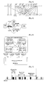
- Figure 1 shows an overview of the UMTS network 100, including the terminal or user equipment (UE) 110, the UTRAN 120 and the core network (CN) 130.
- UE terminal or user equipment
- CN core network
- the UTRAN 120 is composed of several Radio Network Controllers (RNCs) 124, 126 and Node Bs 122, which are connected via the Iub interface. Each RNC may control several Node Bs. Each Node B may control one or several cells, where a cell is characterised by the fact that it covers a given geographical area on a given frequency. Each RNC is connected via the Iu interface to the CN, i.e. towards the MSC (Mobile-services Switching Center) entity 132 of the CN and the SGSN (Serving GPRS Support Node) entity 131. The RNCs can be connected to other RNCs via the Iur interface. The RNC handles the assignment and management of radio resources and operates as an access point with respect to the core network.
- RNCs Radio Network Controllers
- the Node Bs receive information sent by the physical layer of the terminal (UE) through an uplink and transmit data to the terminal through a downlink.
- the Node Bs operate as access points of the UTRAN for the terminal.
- the SGSN is connected via the Gf interface to the EIR (Equipment Identity Register) 133, via the Gs interface to the MSC 132, via the Gn interface to the GGSN (Gateway GPRS Support Node) 135 and via the Gr interface to the HSS (Home Subscriber Server) 134.
- the MSC 132 which controls the connection for CS (circuit switched) services is connected via the NB interface towards the MGW (Media Gateway) 136, via the F interface towards the EIR 133, and via the D interface towards the HSS 134.
- the MGW 136 is connected via the C interface towards the HSS 134, and to the PSTN (Public Switched Telephone Network), and allows adapting of the codecs between the PSTN and the connected RAN.
- PSTN Public Switched Telephone Network
- the GGSN 135 is connected via the Gc interface to the HSS 134, and via the Gi interface to the Internet.
- the GGSN 135 is responsible for routing, charging and separation of data flows into different RABs (Radio Access Bearers).
- the HSS 134 handles the subscription data of the users.
- the UTRAN 120 constructs and maintains a radio access bearer (RAB) for communication between the terminal (UE) 110 and the core network (CN) 130.
- RAB radio access bearer
- the core network requests end-to-end quality of service (QoS) requirements from the RAB, and the RAB supports the QoS requirements the core network has set. Accordingly, by constructing and maintaining the RAB, the UTRAN can satisfy the end-to-end QoS requirements.
- QoS quality of service
- CS circuit switched
- PS packet switched
- the RNCs 124, 126 are connected to the mobile switching center (MSC) 132 of the core network and the MSC 132 is connected to the gateway mobile switching center (GMSC) that manages the connection with other networks.
- the RNCs are connected to the Serving GPRS (General Packet Radio Service) Support Node (SGSN) 131 and the Gateway GPRS Support Node (GGSN) 135 of the core network.
- the SGSN 131 supports the packet communications with the RNCs and the GGSN 135 manages the connection with other packet switched networks, such as the Internet.
- FIG. 2 illustrates a structure of a radio interface protocol between the terminal (UE) and the UTRAN according to the 3GPP radio access network standards.
- the radio interface protocol has horizontal layers comprising a physical layer, a data link layer, and a network layer, and has vertical planes comprising a user plane (U-plane) for transmitting user data and a control plane (C-plane) for transmitting control information.
- the user plane is a region that handles traffic information with the user, such as voice or Internet protocol (IP) packets.
- the control plane is a region that handles control information for an interface with a network, maintenance and management of a call, and the like.
- the protocol layers in Figure 2 can be divided into a first layer (L1), a second layer (L2), and a third layer (L3) based on the three lower layers of an open system interconnection (OSI) standard model.
- the first layer (L1) namely, the physical layer, provides an information transfer service to an upper layer by using various radio transmission techniques.
- the physical layer is connected to an upper layer called a medium access control (MAC) layer, via a transport channel.
- the MAC layer and the physical layer exchange data via the transport channel.
- the second layer (L2) includes a MAC layer, a radio link control (RLC) layer, a broadcast/multicast control (BMC) layer, and a packet data convergence protocol (PDCP) layer.
- RLC radio link control
- BMC broadcast/multicast control
- PDCP packet data convergence protocol
- the MAC layer handles mapping between logical channels and transport channels and provides allocation of the MAC parameters for allocation and re-allocation of radio resources.
- the MAC layer is connected to an upper layer called the radio link control (RLC) layer, via a logical channel.
- RLC radio link control
- Various logical channels are provided according to the type of information transmitted. In general, a control channel is used to transmit information of the control plane and a traffic channel is used to transmit information of the user plane.
- a logical channel may be a common channel or a dedicated channel depending on whether the logical channel is shared.
- Logical channels include a dedicated traffic channel (DTCH), a dedicated control channel (DCCH), a common traffic channel (CTCH), a common control channel (CCCH), a broadcast control channel (BCCH), and a paging control channel (PCCH), or a Shared Control Channel (SCCH) and other channels.
- the BCCH provides information including information utilized by a terminal to access a system.
- the PCCH is used by the UTRAN to access a terminal.
- MBMS multimedia broadcast/multicast services
- MBMS multimedia broadcast/multicast services
- MBMS multimedia broadcast/multicast services
- MBMS multimedia broadcast/multicast services
- MBMS multimedia broadcast/multicast services
- MBMS multimedia broadcast/multicast services
- MBMS multimedia broadcast/multicast services
- MBMS multimedia broadcast/multicast services
- MBMS multimedia broadcast/multicast services
- MBMS MBMS point-to-multipoint Control Channel
- MTCH MBMS point-to-multipoint Traffic Channel
- MSCH MBMS Scheduling Channel
- the MAC layer is connected to the physical layer by transport channels and can be divided into a MAC-b sub-layer, a MAC-d sub-layer, a MAC-c/sh sub-layer, a MAC-hs sub-layer and a MAC-m sublayer according to the type of transport channel being managed.
- the MAC-b sub-layer manages a BCH (Broadcast Channel), which is a transport channel handling the broadcasting of system information.
- the MAC-c/sh sub-layer manages a common transport channel, such as a forward access channel (FACH) or a downlink shared channel (DSCH), which is shared by a plurality of terminals, or in the uplink the Random Access Channel (RACH).
- FACH forward access channel
- DSCH downlink shared channel
- the MAC-m sublayer may handle the MBMS data.
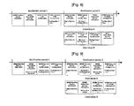
- Figure 3 shows the possible mapping between the logical channels and the transport channels from the UE perspective.
- Figure 4 shows the possible mapping between the logical channels and the transport channels from the UTRAN perspective.
- the MAC-d sub-layer manages a dedicated channel (DCH), which is a dedicated transport channel for a specific terminal.
- the MAC-d sublayer is located in a serving RNC (SRNC) that manages a corresponding terminal, and one MAC-d sublayer also exists in each terminal.
- the RLC layer depending of the RLC mode of operation, supports reliable data transmissions and performs segmentation and concatenation on a plurality of RLC service data units (SDUs) delivered from an upper layer.
- SDUs RLC service data units
- the RLC layer adjusts the size of each RLC SDU in an appropriate manner based upon processing capacity, and then creates data units by adding header information thereto.
- These data units, called protocol data units (PDUs) are transferred to the MAC layer via a logical channel.
- the RLC layer includes a RLC buffer for storing the RLC SDUs and/or the RLC PDUs.
- the BMC layer schedules a cell broadcast (CB) message transferred from the core network and broadcasts the CB message to terminals positioned in a specific cell or cells.
- CB cell broadcast
- the PDCP layer is located above the RLC layer.
- the PDCP layer is used to transmit network protocol data, such as IPv4 or IPv6, efficiently on a radio interface with a relatively small bandwidth.
- the PDCP layer reduces unnecessary control information used in a wired network, namely, a function called header compression is performed.
- the radio resource control (RRC) layer located at the lowest portion of the third layer (L3) is only defined in the control plane.
- the RRC layer controls the transport channels and the physical channels in relation to setup, reconfiguration, and the release or cancellation of the radio bearers (RBs).
- the RB signifies a service provided by the second layer (L2) for data transmission between the terminal and the UTRAN.
- the set up of the RB refers to the process of stipulating the characteristics of a protocol layer and a channel required for providing a specific data service, and setting the respective detailed parameters and operation methods.
- the RRC layer handles user mobility within the RAN, and additional services, e.g., location services.
- Figure 5 shows a UE with channels (DCH, HS-DSCH) established with multiple cells managed by Node Bs, which are controlled by an RNC in a network.
- DCH Downlink Control Channel
- HS-DSCH Downlink Control Channel
- the different possibilities that exist for the mapping between the radio bearers and the transport channels for a given UE are not all possible all the time.
- the UE/UTRAN can deduce the possible mapping depending on the UE state and the procedure that the UE/UTRAN is executing.
- the different states and modes are explained in more detail below, as far as they concern the present invention.
- the different transport channels are mapped onto different physical channels.
- the configuration of the physical channels is given by RRC signalling exchanged between the RNC and the UE.
- the RRC mode refers to whether there exists a logical connection between the RRC of the terminal and the RRC of the UTRAN. If there is a connection, the terminal is said to be in RRC connected mode. If there is no connection, the terminal is said to be in idle mode. Because an RRC connection exists for terminals in RRC connected mode, the UTRAN can determine the existence of a particular terminal within the unit of cells, for example which cell or set of cells the RRC connected mode terminal is in, and which physical channel the UE is listening to. Thus, the terminal can be effectively controlled.
- the UTRAN cannot determine the existence of a terminal in idle mode.
- the existence of idle mode terminals can only be determined by the core network to be within a region that is larger than a cell, for example a location or a routing area. Therefore, the existence of idle mode terminals is determined within large regions, and in order to receive mobile communication services such as voice or data, the idle mode terminal must move or change into the RRC connected mode.
- Figure 6 shows the possible transitions between modes and states of a UE.
- RRC connected mode can be in different states, e.g. CELL-FACH state, CELL-PCH state, CELL_DCH state or URA_PCH state. Other states could exist as well.
- the UE carries out different actions and listens to different channels. For example, a UE in CELL-DCH state will try to listen to DCH type transport channels (amongst other channels), which may comprise DTCH and DCCH transport channels, and which can be mapped to a certain DPCH, DPDSCH, or other physical channels.
- DCH type transport channels (amongst other channels)
- the UE in CELL-FACH state will listen to several FACH transport channels, which are mapped to a certain S-CCPCH.
- the UE in PCH state will listen to the PICH channel, and to the PCH channel that is mapped to a certain S-CCPCH physical channel.
- the network may provide various types of services to a terminal (UE).
- multimedia broadcast/multicast service also referred to as MBMS or MBMS service.
- the UE is supposed to read different messages depending on the situation. For example, the UE should acquire counting, establish RRC connections, receive a MTCH, and the like.
- a particular order is used such that messages for which the content has changed is sent/ received before messages for which the content has not changed.
- MBMS signalling on the MCCH makes use of identifiers to allow reference information to be carried in one message (message A) and which is referred to in another message (message B). These identifiers are valid only for messages that have been read in the same modification period.
- the messages are ordered merely based upon whether or not then- content has changed. Namely, messages containing changed contents are transmitted before messages containing no changed contents.
- this simple condition may not always be optimal.
- a method of scheduling messages (e.g., service information, cell configuration data, control information messages, etc.) is provided such that the terminal (UE) only needs to read a minimum number of messages that are sent from the network.
- certain information that may be needed by the terminal is also considered. Based upon these criteria, the messages are scheduled such that the terminal (UE) would only need to perform minimal reading operations, thus resulting in more efficient reception of services by the terminal based upon improved scheduling performed by the network.
- Figure 1 shows an overview of the UMTS network.
- Figure 2 illustrates a structure of a radio interface protocol between the terminal (UE) and the UTRAN according to the 3GPP radio access network standards.
- Figure 3 shows the possible mapping between the logical channels and the transport channels from the UE perspective.
- Figure 4 shows the possible mapping between the logical channels and the transport channels from the UTRAN perspective.
- Figure 5 shows a UE with channels (DCH, HS-DSCH) established with multiple cells managed by Node Bs, which are controlled by an RNC in a network.
- DCH Downlink Control Channel
- HS-DSCH Downlink Control Channel
- Figure 6 shows the possible transitions between modes and states of a UE.
- Figure 7 shows an example of how different types of MCCH information may be scheduled.
- Figure 8 shows an example of the scheduling of MCCH information at MTCH transmission start.
- Figure 9 shows an example of the scheduling of MCCH Information at session stop.
- One aspect of the present invention is the recognition by the present inventors regarding the problems and drawbacks of the related art described above and explained in more detail hereafter. Based upon such recognition, the features of the present invention have been developed.
- a better determination for ordering or scheduling messages should depend upon multiple factors, such as the particulars of the terminal (UE) (e.g., moving to a new cell, changes in signaling conditions, etc.), the type of service to be received by the terminal (UE), and the like. Namely, the terminal (UE) may need to receive (or read) certain control channels at particular times due to changes in the communications environment. Thus, a more sophisticated scheme for scheduling control information messages is necessary.
- point-to-multipoint services e.g., an MBMS service
- features of the present invention are clearly intended to be applicable to various other types of data transmission and/or reception procedures that would benefit from employing the particular scheduling or ordering of information (or data) according to the present invention.
- MBMS specific procedures will be described.
- reception of MBMS control information will be considered.
- the procedure for receiving MBMS control information is used by a UE to receive information from UTRAN concerning the way it provides MBMS services the UE has joined.
- the procedure applies to all UEs supporting MBMS, irrespective of its state (idle, URA_PCH, CELL_PCH, CELL_FACH and CELL_DCH).
- Figure 7 shows the general principles for scheduling of MCCH information.
- the different shading indicates potentially different content of the MCCH information.
- Most MBMS control information is provided on the MCCH.
- the information on MCCH is transmitted by using a fixed schedule, which is common for all services.
- MCCH information other than MBMS Access Information message is transmitted periodically based on a repetition period. This MCCH information is repeated a configurable number of times with exactly the same content; the period in which the content of MCCH information other than MBMS Access Information message remains unchanged is called the modification period.
- MBMS Access Information message may be transmitted more frequently, based on the Access Info period.
- the transmissions of MBMS Access Information message within a modification period need not have exactly the same content. Namely, the value of some parameters (e.g., IE Access probability factor Idle) may change. Nevertheless, the transmissions of MBMS Access Information message within a modification period should concern the same MBMS service(s), although information for a service may be removed e.g., upon completion of the counting for that service.
- some parameters e.g., IE Access probability factor Idle
- scheduling information may be provided on an MSCH mapped on the same S-CCPCH as the p-t-m radio bearer(s). For some of the services provided p-t-m this scheduling information may be provided by signalling an MBMS Scheduling Information message at every scheduling period, while for others the MBMS Scheduling Information message may be signalled less frequently i.e. after a multiple of the scheduling period. In general, the UE is neither required to acquire MSCH information nor to act on it.
- the UE shall acquire MCCH information that is scheduled at the same time as MSCH information, the reception of the MCCH information shall take precedence.
- UTRAN should schedule the MCCH messages in a specific order. Namely, messages that carry information necessary for UEs that have subscribed to services included in the message MBMS MODIFIED SERVICES INFORMATION in the current modification period should be scheduled prior to the remaining messages. In other words, any message that needs to be read by any UE due to the reception of the MBMS MODIFIED SERVICES INFORMATION message should be scheduled prior to the remaining messages. More specifically, the UE may assume that the UTRAN schedules the MCCH messages in the following order (i.e., sequence, arrangement, etc.):
- Figure 8 shows an example of the scheduling of MCCH information at MTCH transmission start.
- Figure 9 shows an example of the scheduling of MCCH Information at session stop.
- the session stop of active services transmitted on a MTCH configuration is shown.
- the services A and B are active and mapped to the MTCHs.
- the service B stops. Therefore in the modification period 2 the MBMS Current Cell Configuration message content will be changed, and according to the prior art, the message would be sent before the MBMS Unmodified Service Information message, as described in Figure 9 , alternative A.
- the message would be scheduled as non-modified as shown in Figure 9 , alternative B.
- messages that are supposed to be read by UEs that want to receive services listed in the MBMS Modified Service Information should be included before the MBMS Unmodified Service Information message, and the messages that do not contain information necessary for receiving services listed in the MBMS Modified Service Information should be included after the message MBMS Unmodified Service Information contrary to the related art rule that only considers whether the content of the message has changed or not.
- the present invention proposes to clarify the ordering of messages on the MCCH according to the above, i.e. only transmit messages that need to be read by UEs interested in services listed in the MBMS Modified Service Information message before the MBMS Unmodified Service Information message.
- the present invention provides a method of processing control information messages, the method comprising: transmitting a modified services information (MSI) message; transmitting, if necessary after transmitting the MSI message, a first set of messages that is used by any terminal based on the modified services information message; and transmitting an unmodified services information (USI) message after transmitting the MSI message or after transmitting the first set of messages.
- MSI modified services information
- USI unmodified services information
- the method further comprises: transmitting, if necessary after transmitting the USI message, a second set of messages that is not used by any terminal based on the MSI message.
- the messages provide control information for a point-to-multipoint service.
- the messages relate to MCCH information.
- the first set of messages are messages that need to be read by any terminal due to the content of the MSI message.
- the second set of messages are messages that do not need to be read by any terminal due to the content of the MSI message.
- the present invention provides a method of processing control information messages, the method comprising: determining a first set of messages if at least one such message that needs to be read by any terminal based on a modified services information (MSI) message exists; and determining a second set of messages if at least one such message that does not need to be read by any terminal based on the MSI message exists.
- MSI modified services information
- the method further comprises: transmitting the MSI message; transmitting the first set of messages if determined to exist; transmitting an unmodified services information (USI) message; and transmitting the second set of messages if determined to exist.
- MSI MSI message
- USI unmodified services information
- the present invention provides a method of processing control information messages by a terminal, the method comprising: receiving a modified services information (MSI) message; receiving, if necessary after receiving the MSI message, a first set of messages that is used by any terminal based on the modified services information message; and receiving an unmodified services information (USI) message after receiving the MSI message or after receiving the first set of messages.
- MSI modified services information
- USI unmodified services information
- the method further comprises: receiving, if necessary after receiving the USI message, a second set of messages that is not used by any terminal based on the modified services information message.
- the present invention provides a message sequence format for control information messages of a point-to-multipoint service, the format comprising: a modified services information (MSI) message; a first set of messages, immediately following the MSI message, that need to be read by any terminal due to the content of the MSI message; and an unmodified services information (USI) message immediately following the first set of messages.
- MSI modified services information
- USI unmodified services information
- the format further comprises: a second set of messages, immediately following the USI message, that does not need to be read by any terminal due to the content of the MSI message.
- the present invention comprises: a message sequence format for control information messages of a point-to-multipoint service, the format comprising: a modified services information (MSI) message; an unmodified services information (USI) message following the MSI message; and a second set of messages, immediately following the USI message, that does not need to be read by any terminal due to the content of the modified services information message.
- MSI modified services information
- USI unmodified services information
- the format further comprises: a first set of messages, immediately following the MSI message but immediately before the USI message, that need to be read by any terminal due to the content of the modified services information message.
- the present invention provides a message sequence format for control information messages of a point-to-multipoint service, the format comprising: a first message for modified contents; a subsequent message for unmodified contents; and any optional messages, between the first message and the subsequent message, that need to be read by any terminal due to the content of the first message.
- the format further comprises: any optional messages, after the subsequent message, that need not be read by any terminal due to the content of the first message.
- the message sequence format wherein four sequential messages exist for a modification period comprising: a first message containing modified services information, a second message containing current cell configuration information, a third message containing common point-to-multipoint radio bearer configuration information, and a fourth message containing unmodified services information.
Description
- The present invention relates to wireless (radio) communications, and in particular, relates to a method of processing control information messages for point-to-multipoint services.
- The universal mobile telecommunication system (UMTS) is a European-type, third generation IMT-2000 mobile communication system that has evolved from a European standard known as Global System for Mobile communications (GSM). UMTS is intended to provide an improved mobile communication service based upon a GSM core network and wideband code division multiple access (W-CDMA) wireless connection technology. In December 1998, a Third Generation Partnership Project (3GPP) was formed by the ETSI of Europe, the ARIB/TTC of Japan, the T1 of the United States, and the TTA of Korea. The 3GPP creates detailed specifications of UMTS technology. In order to achieve rapid and efficient technical development of the UMTS, five technical specification groups (TSG) have been created within the 3GPP for standardizing the UMTS by considering the independent nature of the network elements and their operations. Each TSG develops, approves, and manages the standard specification within a related region. Among these groups, the radio access network (RAN) group (TSG-RAN) develops the standards for the functions, requirements, and interface of the UMTS terrestrial radio access network (UTRAN), which is a new radio access network for supporting W-CDMA access technology in the UMTS.
-
Figure 1 shows an overview of theUMTS network 100, including the terminal or user equipment (UE) 110, the UTRAN 120 and the core network (CN) 130. - The UTRAN 120 is composed of several Radio Network Controllers (RNCs) 124, 126 and Node
Bs 122, which are connected via the Iub interface. Each RNC may control several Node Bs. Each Node B may control one or several cells, where a cell is characterised by the fact that it covers a given geographical area on a given frequency. Each RNC is connected via the Iu interface to the CN, i.e. towards the MSC (Mobile-services Switching Center)entity 132 of the CN and the SGSN (Serving GPRS Support Node)entity 131. The RNCs can be connected to other RNCs via the Iur interface. The RNC handles the assignment and management of radio resources and operates as an access point with respect to the core network. - The Node Bs receive information sent by the physical layer of the terminal (UE) through an uplink and transmit data to the terminal through a downlink. The Node Bs operate as access points of the UTRAN for the terminal. The SGSN is connected via the Gf interface to the EIR (Equipment Identity Register) 133, via the Gs interface to the MSC 132, via the Gn interface to the GGSN (Gateway GPRS Support Node) 135 and via the Gr interface to the HSS (Home Subscriber Server) 134. The EIR hosts lists of terminals (UEs) which are allowed or are not allowed to be used on the network. The MSC 132 which controls the connection for CS (circuit switched) services is connected via the NB interface towards the MGW (Media Gateway) 136, via the F interface towards the
EIR 133, and via the D interface towards theHSS 134. The MGW 136 is connected via the C interface towards theHSS 134, and to the PSTN (Public Switched Telephone Network), and allows adapting of the codecs between the PSTN and the connected RAN. - The GGSN 135 is connected via the Gc interface to the HSS 134, and via the Gi interface to the Internet. The GGSN 135 is responsible for routing, charging and separation of data flows into different RABs (Radio Access Bearers). The HSS 134 handles the subscription data of the users.
- Other existing connections will not be described in detail, but would be understood by those skilled in the art.
- The UTRAN 120 constructs and maintains a radio access bearer (RAB) for communication between the terminal (UE) 110 and the core network (CN) 130. The core network requests end-to-end quality of service (QoS) requirements from the RAB, and the RAB supports the QoS requirements the core network has set. Accordingly, by constructing and maintaining the RAB, the UTRAN can satisfy the end-to-end QoS requirements.
- The services provided to a specific terminal (UE) are roughly divided into circuit switched (CS) services and packet switched (PS) services. For example, a general voice conversation service is a circuit switched service, while a Web browsing service via an Internet connection is classified as a packet switched (PS) service.
- For supporting circuit switched services, the
RNCs -
Figure 2 illustrates a structure of a radio interface protocol between the terminal (UE) and the UTRAN according to the 3GPP radio access network standards. As shown inFigure 2 , the radio interface protocol has horizontal layers comprising a physical layer, a data link layer, and a network layer, and has vertical planes comprising a user plane (U-plane) for transmitting user data and a control plane (C-plane) for transmitting control information. The user plane is a region that handles traffic information with the user, such as voice or Internet protocol (IP) packets. The control plane is a region that handles control information for an interface with a network, maintenance and management of a call, and the like. - The protocol layers in
Figure 2 can be divided into a first layer (L1), a second layer (L2), and a third layer (L3) based on the three lower layers of an open system interconnection (OSI) standard model. The first layer (L1), namely, the physical layer, provides an information transfer service to an upper layer by using various radio transmission techniques. The physical layer is connected to an upper layer called a medium access control (MAC) layer, via a transport channel. The MAC layer and the physical layer exchange data via the transport channel. The second layer (L2) includes a MAC layer, a radio link control (RLC) layer, a broadcast/multicast control (BMC) layer, and a packet data convergence protocol (PDCP) layer. The MAC layer handles mapping between logical channels and transport channels and provides allocation of the MAC parameters for allocation and re-allocation of radio resources. The MAC layer is connected to an upper layer called the radio link control (RLC) layer, via a logical channel. Various logical channels are provided according to the type of information transmitted. In general, a control channel is used to transmit information of the control plane and a traffic channel is used to transmit information of the user plane. A logical channel may be a common channel or a dedicated channel depending on whether the logical channel is shared. Logical channels include a dedicated traffic channel (DTCH), a dedicated control channel (DCCH), a common traffic channel (CTCH), a common control channel (CCCH), a broadcast control channel (BCCH), and a paging control channel (PCCH), or a Shared Control Channel (SCCH) and other channels. The BCCH provides information including information utilized by a terminal to access a system. The PCCH is used by the UTRAN to access a terminal. - To support point-to-multipoint services, such as multimedia broadcast/multicast services (MBMS or MBMS services), additional traffic and control channels are introduced in the MBMS standard. For example, the MCCH (MBMS point-to-multipoint Control Channel) is used for transmission of MBMS control information, the MTCH (MBMS point-to-multipoint Traffic Channel) is used for transmitting MBMS service data, and the MSCH (MBMS Scheduling Channel) is used to transmit scheduling information.
- The different types of logical channels that exist can be depicted as follows:
-

- The MAC layer is connected to the physical layer by transport channels and can be divided into a MAC-b sub-layer, a MAC-d sub-layer, a MAC-c/sh sub-layer, a MAC-hs sub-layer and a MAC-m sublayer according to the type of transport channel being managed. The MAC-b sub-layer manages a BCH (Broadcast Channel), which is a transport channel handling the broadcasting of system information. The MAC-c/sh sub-layer manages a common transport channel, such as a forward access channel (FACH) or a downlink shared channel (DSCH), which is shared by a plurality of terminals, or in the uplink the Random Access Channel (RACH). The MAC-m sublayer may handle the MBMS data.
-
Figure 3 shows the possible mapping between the logical channels and the transport channels from the UE perspective. -
Figure 4 shows the possible mapping between the logical channels and the transport channels from the UTRAN perspective. - The MAC-d sub-layer manages a dedicated channel (DCH), which is a dedicated transport channel for a specific terminal. The MAC-d sublayer is located in a serving RNC (SRNC) that manages a corresponding terminal, and one MAC-d sublayer also exists in each terminal. The RLC layer, depending of the RLC mode of operation, supports reliable data transmissions and performs segmentation and concatenation on a plurality of RLC service data units (SDUs) delivered from an upper layer. When the RLC layer receives the RLC SDUs from the upper layer, the RLC layer adjusts the size of each RLC SDU in an appropriate manner based upon processing capacity, and then creates data units by adding header information thereto. These data units, called protocol data units (PDUs), are transferred to the MAC layer via a logical channel. The RLC layer includes a RLC buffer for storing the RLC SDUs and/or the RLC PDUs.
- The BMC layer schedules a cell broadcast (CB) message transferred from the core network and broadcasts the CB message to terminals positioned in a specific cell or cells.
- The PDCP layer is located above the RLC layer. The PDCP layer is used to transmit network protocol data, such as IPv4 or IPv6, efficiently on a radio interface with a relatively small bandwidth. For this purpose, the PDCP layer reduces unnecessary control information used in a wired network, namely, a function called header compression is performed.
- The radio resource control (RRC) layer located at the lowest portion of the third layer (L3) is only defined in the control plane. The RRC layer controls the transport channels and the physical channels in relation to setup, reconfiguration, and the release or cancellation of the radio bearers (RBs). The RB signifies a service provided by the second layer (L2) for data transmission between the terminal and the UTRAN. In general, the set up of the RB refers to the process of stipulating the characteristics of a protocol layer and a channel required for providing a specific data service, and setting the respective detailed parameters and operation methods. Additionally, the RRC layer handles user mobility within the RAN, and additional services, e.g., location services.
-
Figure 5 shows a UE with channels (DCH, HS-DSCH) established with multiple cells managed by Node Bs, which are controlled by an RNC in a network. - The different possibilities that exist for the mapping between the radio bearers and the transport channels for a given UE are not all possible all the time. The UE/UTRAN can deduce the possible mapping depending on the UE state and the procedure that the UE/UTRAN is executing. The different states and modes are explained in more detail below, as far as they concern the present invention.
- The different transport channels are mapped onto different physical channels. The configuration of the physical channels is given by RRC signalling exchanged between the RNC and the UE.
- The RRC mode refers to whether there exists a logical connection between the RRC of the terminal and the RRC of the UTRAN. If there is a connection, the terminal is said to be in RRC connected mode. If there is no connection, the terminal is said to be in idle mode. Because an RRC connection exists for terminals in RRC connected mode, the UTRAN can determine the existence of a particular terminal within the unit of cells, for example which cell or set of cells the RRC connected mode terminal is in, and which physical channel the UE is listening to. Thus, the terminal can be effectively controlled.
- In contrast, the UTRAN cannot determine the existence of a terminal in idle mode.
- The existence of idle mode terminals can only be determined by the core network to be within a region that is larger than a cell, for example a location or a routing area. Therefore, the existence of idle mode terminals is determined within large regions, and in order to receive mobile communication services such as voice or data, the idle mode terminal must move or change into the RRC connected mode.
-
Figure 6 shows the possible transitions between modes and states of a UE. A UE in - RRC connected mode can be in different states, e.g. CELL-FACH state, CELL-PCH state, CELL_DCH state or URA_PCH state. Other states could exist as well. Depending on these states, the UE carries out different actions and listens to different channels. For example, a UE in CELL-DCH state will try to listen to DCH type transport channels (amongst other channels), which may comprise DTCH and DCCH transport channels, and which can be mapped to a certain DPCH, DPDSCH, or other physical channels. The UE in CELL-FACH state will listen to several FACH transport channels, which are mapped to a certain S-CCPCH. The UE in PCH state will listen to the PICH channel, and to the PCH channel that is mapped to a certain S-CCPCH physical channel.
- The network (UTRAN) may provide various types of services to a terminal (UE).
- One example would be multimedia broadcast/multicast service, also referred to as MBMS or MBMS service.
- At the start of a service, the UE is supposed to read different messages depending on the situation. For example, the UE should acquire counting, establish RRC connections, receive a MTCH, and the like.
- In order to send and receive these messages, a particular order (sequence or arrangement) is used such that messages for which the content has changed is sent/ received before messages for which the content has not changed.
- MBMS signalling on the MCCH makes use of identifiers to allow reference information to be carried in one message (message A) and which is referred to in another message (message B). These identifiers are valid only for messages that have been read in the same modification period.
- Document "Universal Mobile Telecommunications System (UMTS); Radio Resource Control (RRC) protocol specification (3GPP TS 25.331 version 6.6.0 Release 6); ETSI TS 125 331" ETSI STANDARDS, LIS, SOPHIA ANTIPOLIS CEDEX, FRANCE, vol. 3-R2, no. V6.6.0, 1 June 2005" concerns scheduling of MCCH information. In particular, messages which content has changed compared to a previous modification period are to be scheduled prior to message which content has not changed.
- In the related art, the messages are ordered merely based upon whether or not then- content has changed. Namely, messages containing changed contents are transmitted before messages containing no changed contents. However, this simple condition may not always be optimal.
- Some or all of the above problems are overcome by a method of processing MBMS control information messages having the features of
claim 1 and a method of processing MBMS control information messages having the features of claim 7. - A method of scheduling messages (e.g., service information, cell configuration data, control information messages, etc.) is provided such that the terminal (UE) only needs to read a minimum number of messages that are sent from the network. In addition to whether there are any changes in the content of each message to be scheduled (then transmitted and later received), certain information that may be needed by the terminal is also considered. Based upon these criteria, the messages are scheduled such that the terminal (UE) would only need to perform minimal reading operations, thus resulting in more efficient reception of services by the terminal based upon improved scheduling performed by the network.
-
Figure 1 shows an overview of the UMTS network. -
Figure 2 illustrates a structure of a radio interface protocol between the terminal (UE) and the UTRAN according to the 3GPP radio access network standards. -
Figure 3 shows the possible mapping between the logical channels and the transport channels from the UE perspective. -
Figure 4 shows the possible mapping between the logical channels and the transport channels from the UTRAN perspective. -
Figure 5 shows a UE with channels (DCH, HS-DSCH) established with multiple cells managed by Node Bs, which are controlled by an RNC in a network. -
Figure 6 shows the possible transitions between modes and states of a UE. -
Figure 7 shows an example of how different types of MCCH information may be scheduled. -
Figure 8 shows an example of the scheduling of MCCH information at MTCH transmission start. -
Figure 9 shows an example of the scheduling of MCCH Information at session stop. - One aspect of the present invention is the recognition by the present inventors regarding the problems and drawbacks of the related art described above and explained in more detail hereafter. Based upon such recognition, the features of the present invention have been developed.
- Unlike the related art, a better determination for ordering or scheduling messages should depend upon multiple factors, such as the particulars of the terminal (UE) (e.g., moving to a new cell, changes in signaling conditions, etc.), the type of service to be received by the terminal (UE), and the like. Namely, the terminal (UE) may need to receive (or read) certain control channels at particular times due to changes in the communications environment. Thus, a more sophisticated scheme for scheduling control information messages is necessary.
- Although the following description will refer to point-to-multipoint services (e.g., an MBMS service) merely for the sake of explanation, the features of the present invention are clearly intended to be applicable to various other types of data transmission and/or reception procedures that would benefit from employing the particular scheduling or ordering of information (or data) according to the present invention.
- To illustrate the features of the present invention, MBMS specific procedures will be described. In particular, the reception of MBMS control information will be considered.
- In general, the procedure for receiving MBMS control information is used by a UE to receive information from UTRAN concerning the way it provides MBMS services the UE has joined. The procedure applies to all UEs supporting MBMS, irrespective of its state (idle, URA_PCH, CELL_PCH, CELL_FACH and CELL_DCH).
-
Figure 7 shows the general principles for scheduling of MCCH information. InFigure 7 , the different shading indicates potentially different content of the MCCH information. - Most MBMS control information is provided on the MCCH. The information on MCCH is transmitted by using a fixed schedule, which is common for all services. MCCH information other than MBMS Access Information message is transmitted periodically based on a repetition period. This MCCH information is repeated a configurable number of times with exactly the same content; the period in which the content of MCCH information other than MBMS Access Information message remains unchanged is called the modification period. MBMS Access Information message may be transmitted more frequently, based on the Access Info period.
- The transmissions of MBMS Access Information message within a modification period need not have exactly the same content. Namely, the value of some parameters (e.g., IE Access probability factor Idle) may change. Nevertheless, the transmissions of MBMS Access Information message within a modification period should concern the same MBMS service(s), although information for a service may be removed e.g., upon completion of the counting for that service.
- For services provided via a p-t-m radio bearer scheduling information may be provided on an MSCH mapped on the same S-CCPCH as the p-t-m radio bearer(s). For some of the services provided p-t-m this scheduling information may be provided by signalling an MBMS Scheduling Information message at every scheduling period, while for others the MBMS Scheduling Information message may be signalled less frequently i.e. after a multiple of the scheduling period. In general, the UE is neither required to acquire MSCH information nor to act on it.
- In case the UE shall acquire MCCH information that is scheduled at the same time as MSCH information, the reception of the MCCH information shall take precedence.
- In order to minimize the time the UE needs to read MCCH upon notification to acquire the required information, UTRAN should schedule the MCCH messages in a specific order. Namely, messages that carry information necessary for UEs that have subscribed to services included in the message MBMS MODIFIED SERVICES INFORMATION in the current modification period should be scheduled prior to the remaining messages. In other words, any message that needs to be read by any UE due to the reception of the MBMS MODIFIED SERVICES INFORMATION message should be scheduled prior to the remaining messages. More specifically, the UE may assume that the UTRAN schedules the MCCH messages in the following order (i.e., sequence, arrangement, etc.):
- (1) MBMS MODIFIED SERVICES INFORMATION,
- (2) followed by messages that carry information necessary for UEs that have subscribed to services included in the message MBMS MODIFIED SERVICES INFORMATION in the current modification period (i.e., followed by messages that need to be read by any UE due to the content of the MBMS MODIFIED SERVICES INFORMATION message) - in the following order: MBMS General Information, MBMS Common P-T-M RB Information, MBMS Current Cell P-T-M RB Information, one or more MBMS Neighbouring Cell P-T-M RB Information,
- (3) MBMS Unmodified services Information,
- (4) followed by messages that carry information that is not necessary for UEs that have subscribed to services included in the message MBMS MODIFIED SERVICES INFORMATION in the current modification period (i.e., followed by messages that do not need to be read by any UE due to the content of the MBMS MODIFIED SERVICES INFORMATION message) - in the following order: MBMS General Information, MBMS Common P-T-M RB Information, MBMS Current Cell P-T-M RB Information, one or more MBMS Neighbouring Cell P-T-M RB Information.
-
Figure 8 shows an example of the scheduling of MCCH information at MTCH transmission start. - It is assumed that at session start, no service is active in
Modification Period 1. The Common p-t-m configuration is already transmitted. In theModification Period 2, the start of the new service A and the transmission on MTCH in the current cell is indicated. - Therefore, it seems clear that the MBMS Current Cell Configuration should be transmitted before the MBMS Unmodified Service information since all UEs interested in the new / modified service A need to read it. However, there is some ambiguity versus the MBMS Common P-T-M Configuration message. The content in this example has not changed which suggests to consider it as being not changed, and thus schedule it behind the MBMS Unmodified Service Information message as shown in Alternative A in
Figure 8 . However, this must be read by the UEs that want to read the Service A. Therefore, it would be beneficial for the UE reading to schedule the MBMS Common P-T-M Configuration message before the MBMS Unmodified Service Information message. -
Figure 9 shows an example of the scheduling of MCCH Information at session stop. InFigure 9 , the session stop of active services transmitted on a MTCH configuration is shown. InModification period 1 the services A and B are active and mapped to the MTCHs. In the second modification period the service B stops. Therefore in themodification period 2 the MBMS Current Cell Configuration message content will be changed, and according to the prior art, the message would be sent before the MBMS Unmodified Service Information message, as described inFigure 9 , alternative A. However there is no need that UEs read that message. It is therefore natural that the message would be scheduled as non-modified as shown inFigure 9 , alternative B. - As a general rule, messages that are supposed to be read by UEs that want to receive services listed in the MBMS Modified Service Information should be included before the MBMS Unmodified Service Information message, and the messages that do not contain information necessary for receiving services listed in the MBMS Modified Service Information should be included after the message MBMS Unmodified Service Information contrary to the related art rule that only considers whether the content of the message has changed or not.
- Therefore, the present invention proposes to clarify the ordering of messages on the MCCH according to the above, i.e. only transmit messages that need to be read by UEs interested in services listed in the MBMS Modified Service Information message before the MBMS Unmodified Service Information message.
- The present invention provides a method of processing control information messages, the method comprising: transmitting a modified services information (MSI) message; transmitting, if necessary after transmitting the MSI message, a first set of messages that is used by any terminal based on the modified services information message; and transmitting an unmodified services information (USI) message after transmitting the MSI message or after transmitting the first set of messages.
- Here, the method further comprises: transmitting, if necessary after transmitting the USI message, a second set of messages that is not used by any terminal based on the MSI message. The messages provide control information for a point-to-multipoint service. The messages relate to MCCH information. The first set of messages are messages that need to be read by any terminal due to the content of the MSI message. The second set of messages are messages that do not need to be read by any terminal due to the content of the MSI message.
- Also, the present invention provides a method of processing control information messages, the method comprising: determining a first set of messages if at least one such message that needs to be read by any terminal based on a modified services information (MSI) message exists; and determining a second set of messages if at least one such message that does not need to be read by any terminal based on the MSI message exists.
- The method further comprises: transmitting the MSI message; transmitting the first set of messages if determined to exist; transmitting an unmodified services information (USI) message; and transmitting the second set of messages if determined to exist.
- Additionally, the present invention provides a method of processing control information messages by a terminal, the method comprising: receiving a modified services information (MSI) message; receiving, if necessary after receiving the MSI message, a first set of messages that is used by any terminal based on the modified services information message; and receiving an unmodified services information (USI) message after receiving the MSI message or after receiving the first set of messages.
- The method further comprises: receiving, if necessary after receiving the USI message, a second set of messages that is not used by any terminal based on the modified services information message.
- The method wherein terminal has successfully received a MCCH during a previous modification period. The method wherein the terminal stops reading at an appropriate received message without having to read all received messages.
- Furthermore, the present invention provides a message sequence format for control information messages of a point-to-multipoint service, the format comprising: a modified services information (MSI) message; a first set of messages, immediately following the MSI message, that need to be read by any terminal due to the content of the MSI message; and an unmodified services information (USI) message immediately following the first set of messages.
- The format further comprises: a second set of messages, immediately following the USI message, that does not need to be read by any terminal due to the content of the MSI message.
- Also, the present invention comprises: a message sequence format for control information messages of a point-to-multipoint service, the format comprising: a modified services information (MSI) message; an unmodified services information (USI) message following the MSI message; and a second set of messages, immediately following the USI message, that does not need to be read by any terminal due to the content of the modified services information message.
- The format further comprises: a first set of messages, immediately following the MSI message but immediately before the USI message, that need to be read by any terminal due to the content of the modified services information message.
- The present invention provides a message sequence format for control information messages of a point-to-multipoint service, the format comprising: a first message for modified contents; a subsequent message for unmodified contents; and any optional messages, between the first message and the subsequent message, that need to be read by any terminal due to the content of the first message.
- The format further comprises: any optional messages, after the subsequent message, that need not be read by any terminal due to the content of the first message.
- The message sequence format wherein four sequential messages exist for a modification period, comprising: a first message containing modified services information, a second message containing current cell configuration information, a third message containing common point-to-multipoint radio bearer configuration information, and a fourth message containing unmodified services information.
- This specification describes various illustrative embodiments of the present invention. The scope of the claims is intended to cover various modifications and equivalent arrangements of the illustrative embodiments disclosed in the specification.
Claims (12)
- A method of processing MBMS control information messages for UEs (110) having subscribed to MBMS services, the method comprising:transmitting a modified MBMS services information, MSI, message;transmitting, after transmitting the modified MBMS services information, MSI, message, an unmodified MBMS services information, USI, message; andtransmitting at least one of a first set of messages and a second set of messages, characterized in thatthe first set of messages, which follows the modified MBMS services information, MSI, message, needs to be read by the UEs (110) based on the modified MBMS services information, MSI, message, and the second set of messages, which follows the unmodified MBMS services information, USI, message, needs not to be read by the UEs(110) based on the modified MBMS services information, MSI, message.
- The method claim 1, further comprising:transmitting, after transmitting the unmodified MBMS services information, USI, message, the second set of messages that carry information not necessary for UEs (110) that have subscribed to services included in the modified MBMS services information, MSI, message.
- The method of claim 2, wherein the messages provide control information for a point-to-multipoint service.
- The method of claim 3, wherein the messages relate to MBMS Control Channel, MCCH, information.
- The method of claim 1, wherein the first set of messages are messages that need to be read by the UEs (110) due to the content of the modified MBMS services information, MSI, message.
- The method of claim 1, wherein the second set of messages are messages that do not need to be read by the UEs (110) due to the content of the modified MBMS services information, MSI, message.
- A method of processing MBMS control information messages by an UE (110) having subscribed to MBMS services, the method comprising:receiving a modified MBMS services information, MSI, message;receiving, after receiving the modified MBMS services information, MSI, message, an unmodified MBMS services information, USI, message; andreceiving at least one of a first set of messages and a second set of messages, characterized in thatthe first set of messages, which follows the modified MBMS services information, MSI, message, needs to be read by the UEs (110) based on the modified MBMS services information, MSI, message, and the second set of messages, which follows the unmodified MBMS services information, USI, message, needs not to be read by the UEs (110) based on the modified MBMS services information, MSI, message.
- The method of claim 7, further comprising:receiving, after receiving the unmodified MBMS services information, USI, message, the second set of messages that carry information not necessary for UEs (110) that have subscribed to services included in the modified MBMS services information, MSI, message.
- The method of claim 8, wherein the UEs (110) have successfully received a MBMS Control Channel, MCCH, during a previous modification period.
- The method of claim 9, wherein the UEs (110) stop reading an appropriately received message without reading all received messages.
- The method of claim 7, wherein the first set of messages are messages that need to be read by the UEs (110) due to the content of the modified MBMS services information, MSI, message.
- The method of claim 7, wherein the second set of messages are messages that do not need to be read by the UEs (110) due to the content of the modified MBMS services information, MSI, message.
Applications Claiming Priority (2)
| Application Number | Priority Date | Filing Date | Title |
|---|---|---|---|
| US71053605P | 2005-08-22 | 2005-08-22 | |
| PCT/KR2006/003299 WO2007024090A1 (en) | 2005-08-22 | 2006-08-22 | Method of processing control information messages for point-to-multipoint services |
Publications (3)
| Publication Number | Publication Date |
|---|---|
| EP1925176A1 EP1925176A1 (en) | 2008-05-28 |
| EP1925176A4 EP1925176A4 (en) | 2010-04-07 |
| EP1925176B1 true EP1925176B1 (en) | 2013-08-14 |
Family
ID=37771799
Family Applications (1)
| Application Number | Title | Priority Date | Filing Date |
|---|---|---|---|
| EP06783695.7A Active EP1925176B1 (en) | 2005-08-22 | 2006-08-22 | Method of processing control information messages for point-to-multipoint services |
Country Status (12)
| Country | Link |
|---|---|
| US (1) | US8433346B2 (en) |
| EP (1) | EP1925176B1 (en) |
| JP (1) | JP4753995B2 (en) |
| KR (1) | KR101247851B1 (en) |
| CN (1) | CN101243722B (en) |
| AU (1) | AU2006282187B2 (en) |
| BR (1) | BRPI0615200B1 (en) |
| MX (1) | MX2008001335A (en) |
| RU (1) | RU2414098C2 (en) |
| TW (1) | TWI359622B (en) |
| WO (1) | WO2007024090A1 (en) |
| ZA (1) | ZA200800380B (en) |
Families Citing this family (17)
| Publication number | Priority date | Publication date | Assignee | Title |
|---|---|---|---|---|
| CN1476259A (en) * | 2002-08-16 | 2004-02-18 | ��������ͨ�ż����о�����˾ | Multi media broadcasting and method of organizing broadcasting business call finding |
| EP1811674A1 (en) * | 2006-01-23 | 2007-07-25 | Motorola, Inc. | Apparatus and methods for jointly decoding messages based on apriori knowledge of modified codeword transmission |
| EP1850616A1 (en) * | 2006-04-28 | 2007-10-31 | Nec Technologies (UK) Limited | Method for optimizing the reading by a user equipment of MCCH (MBMS point-to-multipoint control channel) information |
| JP4728203B2 (en) * | 2006-11-06 | 2011-07-20 | 富士通セミコンダクター株式会社 | Semiconductor circuit layout method, program, and design support system |
| KR100831983B1 (en) * | 2006-12-08 | 2008-05-23 | 한국전자통신연구원 | Apparatus and method for uplink framing in communication system |
| US8189581B2 (en) * | 2007-06-20 | 2012-05-29 | Motorola Mobility, Inc. | Method, signal and apparatus for managing the transmission and receipt of broadcast channel information |
| US20080316995A1 (en) | 2007-06-20 | 2008-12-25 | Motorola, Inc. | Broadcast channel signal and apparatus for managing the transmission and receipt of broadcast channel information |
| US7899051B2 (en) | 2007-12-31 | 2011-03-01 | Motorola Mobility, Inc. | Broadcast channel signal, apparatus and method for transmitting and decoding broadcast channel information |
| CN101605041B (en) * | 2008-09-18 | 2011-04-06 | 华为技术有限公司 | Method, device and system for configuring multicast unifrequent network sources |
| US8553726B2 (en) * | 2009-04-23 | 2013-10-08 | Lg Electronics Inc. | Scheduling transmission of messages relating to multimedia broadcast/multicast service (MBMS) |
| CN102308532B (en) * | 2009-05-21 | 2013-10-09 | 华为终端有限公司 | Method, system and server for processing point to multi-point push message |
| TWI428036B (en) * | 2009-06-08 | 2014-02-21 | Innovative Sonic Corp | Method and apparatus for handling mbms dynamic scheduling information |
| CN102202262B (en) * | 2010-03-25 | 2014-12-10 | 中兴通讯股份有限公司 | User equipment and method for acquiring multicast control information |
| CN104023316B (en) * | 2013-03-01 | 2017-11-17 | 华为技术有限公司 | Multicast information transmission method and apparatus |
| US10057311B2 (en) * | 2015-08-13 | 2018-08-21 | Lg Electronics Inc. | Method of transmitting system information with extended DRX cycle in wireless communication system and apparatus therefor |
| CN106470400B (en) * | 2015-08-14 | 2020-11-20 | 中兴通讯股份有限公司 | Resource allocation method, system and device for single-cell multicast control channel |
| US10299272B2 (en) * | 2016-11-04 | 2019-05-21 | Nokia Solutions And Networks Oy | Switching carrier frequency while user equipment is in off cycle |
Family Cites Families (20)
| Publication number | Priority date | Publication date | Assignee | Title |
|---|---|---|---|---|
| KR20030032875A (en) | 2001-10-19 | 2003-04-26 | 삼성전자주식회사 | Apparatus for controlling transmit power of downlink data channel in mobile communication system serving multimedia broadcast/multicast service and method thereof |
| KR100958519B1 (en) * | 2002-08-14 | 2010-05-17 | 엘지전자 주식회사 | Method for receive and transmission in mobile communications system |
| US20040227618A1 (en) | 2002-11-06 | 2004-11-18 | Samsung Electronics Co., Ltd. | Paging method in a mobile communication system providing a multimedia broadcast/multicast service |
| US7586874B2 (en) | 2003-01-06 | 2009-09-08 | Interdigital Technology Corporation | Wireless communication method and apparatus for providing multimedia broadcast services |
| EP1467586B1 (en) | 2003-04-09 | 2010-05-19 | Samsung Electronics Co., Ltd. | Method for cell reselection in an MBMS mobile communication system |
| KR100703380B1 (en) | 2003-05-14 | 2007-04-03 | 삼성전자주식회사 | Apparatus and method for transmitting/receiving control information for multimedia broadcast/multicast service |
| EP1642405B1 (en) | 2003-07-09 | 2015-09-09 | Samsung Electronics Co., Ltd. | Initiation of an uplink signaling by mbms ue |
| KR100651405B1 (en) | 2003-07-24 | 2006-11-29 | 삼성전자주식회사 | Apparatus and method for transmission/reception of control information mbms mobile communication |
| KR20050015544A (en) | 2003-08-06 | 2005-02-21 | 삼성전자주식회사 | Method for effectively providing mbms service to an user missed a first paging message in a mobile communication system |
| KR20050020458A (en) | 2003-08-22 | 2005-03-04 | 삼성전자주식회사 | Methods for paging user equipment with dedicated channel in a mobile communication system which support mbms |
| BRPI0413816B1 (en) | 2003-08-22 | 2018-04-10 | Samsung Electronics Co., Ltd. | CELL SELECTION METHOD FOR RECEIVING PACKAGE DATA IN A MBMS SUPPORT MOBILE COMMUNICATION SYSTEM |
| US20050070277A1 (en) | 2003-09-30 | 2005-03-31 | Teck Hu | Method of initiating multimedia broadcast multicast services |
| US20050118992A1 (en) | 2003-10-02 | 2005-06-02 | Samsung Electronics Co., Ltd. | Method of transmitting and receiving service availability information about a multimedia broadcast/multicast service |
| US8437347B2 (en) | 2003-10-14 | 2013-05-07 | Qualcomm Incorporated | Scalable encoding for multicast broadcast multimedia service |
| JP4263632B2 (en) | 2004-02-06 | 2009-05-13 | 株式会社エヌ・ティ・ティ・ドコモ | Distribution path database server, node device, broadcast service distribution control system, and broadcast service distribution control method |
| US8144735B2 (en) * | 2004-02-10 | 2012-03-27 | Qualcomm Incorporated | Transmission of signaling information for broadcast and multicast services |
| KR20050101006A (en) * | 2004-04-16 | 2005-10-20 | 삼성전자주식회사 | Method for the efficient transmission of the control message for mbms in mobile communication |
| US7546132B2 (en) * | 2004-04-19 | 2009-06-09 | Lg Electronics, Inc. | Communication of point to multipoint service information in wireless communication system |
| KR101114104B1 (en) * | 2004-08-12 | 2012-02-21 | 엘지전자 주식회사 | Reception in dedicated service of wireless communication system |
| EP1708413A1 (en) * | 2005-03-29 | 2006-10-04 | Lg Electronics Inc. | Multimedia broadcast/multicast service (MBMS) cells reconfigurations |
-
2006
- 2006-08-22 RU RU2008100313/09A patent/RU2414098C2/en active
- 2006-08-22 BR BRPI0615200-7A patent/BRPI0615200B1/en active IP Right Grant
- 2006-08-22 MX MX2008001335A patent/MX2008001335A/en active IP Right Grant
- 2006-08-22 WO PCT/KR2006/003299 patent/WO2007024090A1/en active Application Filing
- 2006-08-22 US US11/466,363 patent/US8433346B2/en active Active
- 2006-08-22 EP EP06783695.7A patent/EP1925176B1/en active Active
- 2006-08-22 KR KR1020087003353A patent/KR101247851B1/en active IP Right Grant
- 2006-08-22 AU AU2006282187A patent/AU2006282187B2/en active Active
- 2006-08-22 TW TW095130914A patent/TWI359622B/en active
- 2006-08-22 CN CN2006800304015A patent/CN101243722B/en active Active
- 2006-08-22 JP JP2008523811A patent/JP4753995B2/en active Active
-
2008
- 2008-01-10 ZA ZA200800380A patent/ZA200800380B/en unknown
Also Published As
| Publication number | Publication date |
|---|---|
| AU2006282187A1 (en) | 2007-03-01 |
| EP1925176A4 (en) | 2010-04-07 |
| EP1925176A1 (en) | 2008-05-28 |
| BRPI0615200B1 (en) | 2019-07-09 |
| JP2009503988A (en) | 2009-01-29 |
| KR20080046162A (en) | 2008-05-26 |
| AU2006282187B2 (en) | 2009-09-03 |
| US20070042794A1 (en) | 2007-02-22 |
| CN101243722A (en) | 2008-08-13 |
| RU2414098C2 (en) | 2011-03-10 |
| CN101243722B (en) | 2011-12-07 |
| MX2008001335A (en) | 2008-03-24 |
| ZA200800380B (en) | 2009-08-26 |
| TWI359622B (en) | 2012-03-01 |
| TW200721860A (en) | 2007-06-01 |
| WO2007024090A1 (en) | 2007-03-01 |
| JP4753995B2 (en) | 2011-08-24 |
| KR101247851B1 (en) | 2013-03-26 |
| US8433346B2 (en) | 2013-04-30 |
| BRPI0615200A2 (en) | 2011-05-10 |
| RU2008100313A (en) | 2009-09-27 |
Similar Documents
| Publication | Publication Date | Title |
|---|---|---|
| EP1925176B1 (en) | Method of processing control information messages for point-to-multipoint services | |
| KR100893070B1 (en) | Method and apparatus for providing and receiving multicast service in a radio communication system | |
| US8472387B2 (en) | Point to point radio bearers for a broadcasting service | |
| US8014376B2 (en) | Managing channel configuration information in a wireless communication system | |
| US7636331B2 (en) | Transmission of control information in wireless communication system | |
| KR100932485B1 (en) | How to Provide Broadcast and / or Multicast Services | |
| KR20040026153A (en) | Method and apparatus for providing multicast service over a shared channel in a radio communication | |
| KR100952679B1 (en) | CBS message transmitting method and mobile communication system using the same |
Legal Events
| Date | Code | Title | Description |
|---|---|---|---|
| PUAI | Public reference made under article 153(3) epc to a published international application that has entered the european phase |
Free format text: ORIGINAL CODE: 0009012 |
|
| 17P | Request for examination filed |
Effective date: 20080307 |
|
| AK | Designated contracting states |
Kind code of ref document: A1 Designated state(s): AT BE BG CH CY CZ DE DK EE ES FI FR GB GR HU IE IS IT LI LT LU LV MC NL PL PT RO SE SI SK TR |
|
| A4 | Supplementary search report drawn up and despatched |
Effective date: 20100304 |
|
| 17Q | First examination report despatched |
Effective date: 20100628 |
|
| RAP1 | Party data changed (applicant data changed or rights of an application transferred) |
Owner name: LG ELECTRONICS INC. |
|
| DAX | Request for extension of the european patent (deleted) | ||
| REG | Reference to a national code |
Ref country code: DE Ref legal event code: R079 Ref document number: 602006037861 Country of ref document: DE Free format text: PREVIOUS MAIN CLASS: H04Q0007380000 Ipc: H04W0072120000 |
|
| RIC1 | Information provided on ipc code assigned before grant |
Ipc: H04W 72/12 20090101AFI20130110BHEP |
|
| GRAP | Despatch of communication of intention to grant a patent |
Free format text: ORIGINAL CODE: EPIDOSNIGR1 |
|
| GRAS | Grant fee paid |
Free format text: ORIGINAL CODE: EPIDOSNIGR3 |
|
| GRAA | (expected) grant |
Free format text: ORIGINAL CODE: 0009210 |
|
| AK | Designated contracting states |
Kind code of ref document: B1 Designated state(s): AT BE BG CH CY CZ DE DK EE ES FI FR GB GR HU IE IS IT LI LT LU LV MC NL PL PT RO SE SI SK TR |
|
| REG | Reference to a national code |
Ref country code: GB Ref legal event code: FG4D |
|
| REG | Reference to a national code |
Ref country code: AT Ref legal event code: REF Ref document number: 627461 Country of ref document: AT Kind code of ref document: T Effective date: 20130815 Ref country code: CH Ref legal event code: EP |
|
| REG | Reference to a national code |
Ref country code: IE Ref legal event code: FG4D |
|
| REG | Reference to a national code |
Ref country code: DE Ref legal event code: R096 Ref document number: 602006037861 Country of ref document: DE Effective date: 20131010 |
|
| REG | Reference to a national code |
Ref country code: AT Ref legal event code: MK05 Ref document number: 627461 Country of ref document: AT Kind code of ref document: T Effective date: 20130814 Ref country code: NL Ref legal event code: VDEP Effective date: 20130814 |
|
| REG | Reference to a national code |
Ref country code: LT Ref legal event code: MG4D |
|
| PG25 | Lapsed in a contracting state [announced via postgrant information from national office to epo] |
Ref country code: AT Free format text: LAPSE BECAUSE OF FAILURE TO SUBMIT A TRANSLATION OF THE DESCRIPTION OR TO PAY THE FEE WITHIN THE PRESCRIBED TIME-LIMIT Effective date: 20130814 Ref country code: LT Free format text: LAPSE BECAUSE OF FAILURE TO SUBMIT A TRANSLATION OF THE DESCRIPTION OR TO PAY THE FEE WITHIN THE PRESCRIBED TIME-LIMIT Effective date: 20130814 Ref country code: SE Free format text: LAPSE BECAUSE OF FAILURE TO SUBMIT A TRANSLATION OF THE DESCRIPTION OR TO PAY THE FEE WITHIN THE PRESCRIBED TIME-LIMIT Effective date: 20130814 Ref country code: CY Free format text: LAPSE BECAUSE OF FAILURE TO SUBMIT A TRANSLATION OF THE DESCRIPTION OR TO PAY THE FEE WITHIN THE PRESCRIBED TIME-LIMIT Effective date: 20130724 Ref country code: PT Free format text: LAPSE BECAUSE OF FAILURE TO SUBMIT A TRANSLATION OF THE DESCRIPTION OR TO PAY THE FEE WITHIN THE PRESCRIBED TIME-LIMIT Effective date: 20131216 Ref country code: IS Free format text: LAPSE BECAUSE OF FAILURE TO SUBMIT A TRANSLATION OF THE DESCRIPTION OR TO PAY THE FEE WITHIN THE PRESCRIBED TIME-LIMIT Effective date: 20131214 |
|
| PG25 | Lapsed in a contracting state [announced via postgrant information from national office to epo] |
Ref country code: PL Free format text: LAPSE BECAUSE OF FAILURE TO SUBMIT A TRANSLATION OF THE DESCRIPTION OR TO PAY THE FEE WITHIN THE PRESCRIBED TIME-LIMIT Effective date: 20130814 Ref country code: FI Free format text: LAPSE BECAUSE OF FAILURE TO SUBMIT A TRANSLATION OF THE DESCRIPTION OR TO PAY THE FEE WITHIN THE PRESCRIBED TIME-LIMIT Effective date: 20130814 Ref country code: LV Free format text: LAPSE BECAUSE OF FAILURE TO SUBMIT A TRANSLATION OF THE DESCRIPTION OR TO PAY THE FEE WITHIN THE PRESCRIBED TIME-LIMIT Effective date: 20130814 Ref country code: BE Free format text: LAPSE BECAUSE OF FAILURE TO SUBMIT A TRANSLATION OF THE DESCRIPTION OR TO PAY THE FEE WITHIN THE PRESCRIBED TIME-LIMIT Effective date: 20130814 Ref country code: GR Free format text: LAPSE BECAUSE OF FAILURE TO SUBMIT A TRANSLATION OF THE DESCRIPTION OR TO PAY THE FEE WITHIN THE PRESCRIBED TIME-LIMIT Effective date: 20131115 Ref country code: SI Free format text: LAPSE BECAUSE OF FAILURE TO SUBMIT A TRANSLATION OF THE DESCRIPTION OR TO PAY THE FEE WITHIN THE PRESCRIBED TIME-LIMIT Effective date: 20130814 |
|
| PG25 | Lapsed in a contracting state [announced via postgrant information from national office to epo] |
Ref country code: CY Free format text: LAPSE BECAUSE OF FAILURE TO SUBMIT A TRANSLATION OF THE DESCRIPTION OR TO PAY THE FEE WITHIN THE PRESCRIBED TIME-LIMIT Effective date: 20130814 |
|
| REG | Reference to a national code |
Ref country code: CH Ref legal event code: PL |
|
| PG25 | Lapsed in a contracting state [announced via postgrant information from national office to epo] |
Ref country code: LI Free format text: LAPSE BECAUSE OF NON-PAYMENT OF DUE FEES Effective date: 20130831 Ref country code: CZ Free format text: LAPSE BECAUSE OF FAILURE TO SUBMIT A TRANSLATION OF THE DESCRIPTION OR TO PAY THE FEE WITHIN THE PRESCRIBED TIME-LIMIT Effective date: 20130814 Ref country code: DK Free format text: LAPSE BECAUSE OF FAILURE TO SUBMIT A TRANSLATION OF THE DESCRIPTION OR TO PAY THE FEE WITHIN THE PRESCRIBED TIME-LIMIT Effective date: 20130814 Ref country code: SK Free format text: LAPSE BECAUSE OF FAILURE TO SUBMIT A TRANSLATION OF THE DESCRIPTION OR TO PAY THE FEE WITHIN THE PRESCRIBED TIME-LIMIT Effective date: 20130814 Ref country code: CH Free format text: LAPSE BECAUSE OF NON-PAYMENT OF DUE FEES Effective date: 20130831 Ref country code: RO Free format text: LAPSE BECAUSE OF FAILURE TO SUBMIT A TRANSLATION OF THE DESCRIPTION OR TO PAY THE FEE WITHIN THE PRESCRIBED TIME-LIMIT Effective date: 20130814 Ref country code: EE Free format text: LAPSE BECAUSE OF FAILURE TO SUBMIT A TRANSLATION OF THE DESCRIPTION OR TO PAY THE FEE WITHIN THE PRESCRIBED TIME-LIMIT Effective date: 20130814 Ref country code: NL Free format text: LAPSE BECAUSE OF FAILURE TO SUBMIT A TRANSLATION OF THE DESCRIPTION OR TO PAY THE FEE WITHIN THE PRESCRIBED TIME-LIMIT Effective date: 20130814 |
|
| REG | Reference to a national code |
Ref country code: IE Ref legal event code: MM4A |
|
| PG25 | Lapsed in a contracting state [announced via postgrant information from national office to epo] |
Ref country code: MC Free format text: LAPSE BECAUSE OF FAILURE TO SUBMIT A TRANSLATION OF THE DESCRIPTION OR TO PAY THE FEE WITHIN THE PRESCRIBED TIME-LIMIT Effective date: 20130814 Ref country code: IT Free format text: LAPSE BECAUSE OF FAILURE TO SUBMIT A TRANSLATION OF THE DESCRIPTION OR TO PAY THE FEE WITHIN THE PRESCRIBED TIME-LIMIT Effective date: 20130814 Ref country code: ES Free format text: LAPSE BECAUSE OF FAILURE TO SUBMIT A TRANSLATION OF THE DESCRIPTION OR TO PAY THE FEE WITHIN THE PRESCRIBED TIME-LIMIT Effective date: 20130814 |
|
| PLBE | No opposition filed within time limit |
Free format text: ORIGINAL CODE: 0009261 |
|
| STAA | Information on the status of an ep patent application or granted ep patent |
Free format text: STATUS: NO OPPOSITION FILED WITHIN TIME LIMIT |
|
| REG | Reference to a national code |
Ref country code: FR Ref legal event code: ST Effective date: 20140618 |
|
| 26N | No opposition filed |
Effective date: 20140515 |
|
| PG25 | Lapsed in a contracting state [announced via postgrant information from national office to epo] |
Ref country code: IE Free format text: LAPSE BECAUSE OF NON-PAYMENT OF DUE FEES Effective date: 20130822 |
|
| REG | Reference to a national code |
Ref country code: DE Ref legal event code: R097 Ref document number: 602006037861 Country of ref document: DE Effective date: 20140515 |
|
| PG25 | Lapsed in a contracting state [announced via postgrant information from national office to epo] |
Ref country code: FR Free format text: LAPSE BECAUSE OF NON-PAYMENT OF DUE FEES Effective date: 20131014 |
|
| PG25 | Lapsed in a contracting state [announced via postgrant information from national office to epo] |
Ref country code: TR Free format text: LAPSE BECAUSE OF FAILURE TO SUBMIT A TRANSLATION OF THE DESCRIPTION OR TO PAY THE FEE WITHIN THE PRESCRIBED TIME-LIMIT Effective date: 20130814 |
|
| PG25 | Lapsed in a contracting state [announced via postgrant information from national office to epo] |
Ref country code: LU Free format text: LAPSE BECAUSE OF NON-PAYMENT OF DUE FEES Effective date: 20130822 Ref country code: HU Free format text: LAPSE BECAUSE OF FAILURE TO SUBMIT A TRANSLATION OF THE DESCRIPTION OR TO PAY THE FEE WITHIN THE PRESCRIBED TIME-LIMIT; INVALID AB INITIO Effective date: 20060822 Ref country code: BG Free format text: LAPSE BECAUSE OF FAILURE TO SUBMIT A TRANSLATION OF THE DESCRIPTION OR TO PAY THE FEE WITHIN THE PRESCRIBED TIME-LIMIT Effective date: 20130814 |
|
| PGFP | Annual fee paid to national office [announced via postgrant information from national office to epo] |
Ref country code: GB Payment date: 20230705 Year of fee payment: 18 |
|
| PGFP | Annual fee paid to national office [announced via postgrant information from national office to epo] |
Ref country code: DE Payment date: 20230705 Year of fee payment: 18 |