EP1923816B1 - Method and system for tuning an RFID interrogator - Google Patents
Method and system for tuning an RFID interrogator Download PDFInfo
- Publication number
- EP1923816B1 EP1923816B1 EP07253985A EP07253985A EP1923816B1 EP 1923816 B1 EP1923816 B1 EP 1923816B1 EP 07253985 A EP07253985 A EP 07253985A EP 07253985 A EP07253985 A EP 07253985A EP 1923816 B1 EP1923816 B1 EP 1923816B1
- Authority
- EP
- European Patent Office
- Prior art keywords
- radio frequency
- interrogator
- signal
- rfid
- frequency signal
- Prior art date
- Legal status (The legal status is an assumption and is not a legal conclusion. Google has not performed a legal analysis and makes no representation as to the accuracy of the status listed.)
- Active
Links
- 238000000034 method Methods 0.000 title claims description 21
- 238000010183 spectrum analysis Methods 0.000 claims description 11
- 239000000872 buffer Substances 0.000 claims description 10
- 238000004891 communication Methods 0.000 claims description 7
- 238000012545 processing Methods 0.000 claims description 5
- 238000007619 statistical method Methods 0.000 claims description 5
- 230000008569 process Effects 0.000 description 6
- 230000004044 response Effects 0.000 description 5
- 230000003068 static effect Effects 0.000 description 5
- 238000010586 diagram Methods 0.000 description 4
- 239000008267 milk Substances 0.000 description 4
- 210000004080 milk Anatomy 0.000 description 4
- 235000013336 milk Nutrition 0.000 description 4
- 230000002411 adverse Effects 0.000 description 3
- 230000001052 transient effect Effects 0.000 description 3
- 230000005540 biological transmission Effects 0.000 description 2
- 230000008520 organization Effects 0.000 description 2
- 235000010627 Phaseolus vulgaris Nutrition 0.000 description 1
- 244000046052 Phaseolus vulgaris Species 0.000 description 1
- 230000001413 cellular effect Effects 0.000 description 1
- 230000008859 change Effects 0.000 description 1
- 230000003247 decreasing effect Effects 0.000 description 1
- 238000013461 design Methods 0.000 description 1
- 239000003814 drug Substances 0.000 description 1
- 238000005516 engineering process Methods 0.000 description 1
- 238000012986 modification Methods 0.000 description 1
- 230000004048 modification Effects 0.000 description 1
- 238000004806 packaging method and process Methods 0.000 description 1
- 230000035945 sensitivity Effects 0.000 description 1
- 230000002747 voluntary effect Effects 0.000 description 1
Images

Classifications
-
- G—PHYSICS
- G06—COMPUTING; CALCULATING OR COUNTING
- G06K—GRAPHICAL DATA READING; PRESENTATION OF DATA; RECORD CARRIERS; HANDLING RECORD CARRIERS
- G06K7/00—Methods or arrangements for sensing record carriers, e.g. for reading patterns
- G06K7/0008—General problems related to the reading of electronic memory record carriers, independent of its reading method, e.g. power transfer
-
- H—ELECTRICITY
- H04—ELECTRIC COMMUNICATION TECHNIQUE
- H04B—TRANSMISSION
- H04B17/00—Monitoring; Testing
- H04B17/20—Monitoring; Testing of receivers
- H04B17/26—Monitoring; Testing of receivers using historical data, averaging values or statistics
-
- H—ELECTRICITY
- H04—ELECTRIC COMMUNICATION TECHNIQUE
- H04B—TRANSMISSION
- H04B17/00—Monitoring; Testing
- H04B17/30—Monitoring; Testing of propagation channels
- H04B17/309—Measuring or estimating channel quality parameters
- H04B17/318—Received signal strength
-
- H—ELECTRICITY
- H04—ELECTRIC COMMUNICATION TECHNIQUE
- H04B—TRANSMISSION
- H04B17/00—Monitoring; Testing
- H04B17/30—Monitoring; Testing of propagation channels
- H04B17/309—Measuring or estimating channel quality parameters
- H04B17/345—Interference values
Definitions
- An embodiment of the present invention relates generally to Radio Frequency Identification.
- Radio Frequency Identification systems are employed to identify and thus track a wide array of objects.
- RFID Radio Frequency Identification
- Some examples of objects that use RFID technology for identification and tracking are documents (i.e., passports and driver's license), retail merchandise, portable electronics, furniture, parts, pharmaceuticals, and shipping containers.
- the RFID systems comprise one or more RFID interrogators that read information stored in RFID tags and a computer for processing the information.
- the RFID tag is normally attached directly to an object or is placed inside packaging that contains the object. Whenever an RFID tag is within range of an RFID interrogator, the RFID interrogator reads the information encoded on the RFID tag.
- Protocol parameters control the transmission of an RF reply signal by an RFID tag.
- the values for the different protocol parameters are determined by the RFID interrogator and transmitted to the RFID tags, which then use the parameters to generate and transmit RF reply signals.
- US published patent application no. US 2004/0179588 details such a system which prior art is acknowledged in the preamble of claims 1 and 6. Properly set the protocol parameters will increase the probability that an RFID interrogator will accurately read all RFID tags within range even in the presence of ambient noise.
- the RFID interrogator will fail to read some or all of the RFID tags within the range of the RFID interrogator. Therefore, it is desirable for the RFID interrogator to be able to determine proper values for the protocol parameters to be able to read all RFID tags within range.
- an exemplary illustration of an RFID system 10 comprises an RFID interrogator 15 (also referred to as an RFID tag reader or RFID reader), ambient noise 40, and multiple objects 20, 25, 30, 35 each containing an RFID tag 50, 55, 60, 65.
- Each of the RFID tags contains information that identifies the RFID tag and by association the object.
- the information stored on each RFID tag may uniquely identify each RFID tag from all other RFID tags or the information may identify an RFID tag as belonging to a certain group (e.g., a one-gallon container of milk).
- RFID tags contain additional information beyond what is necessary to uniquely identify a tag or to identify a group.
- the RFID tag may contain information identifying a unique one-gallon container of milk from all other containers of milk plus have additional information specifying the supplier, lot number, and expiration date of the milk.
- the RFID interrogator 15 is designed to read the information from each RFID tag 50, 55, 60, 65 that is within the RFID interrogator's 15 range 45.
- the RFID interrogator 15 reads information stored on an RFID tag by transmitting a radio frequency (RF) signal. This signal is referred to as a query signal or query command.
- RF radio frequency
- the query signal is received by all RFID tags 50, 55, 60, 65 that are in range 45 of the RFID interrogator 15.
- the RFID tags then transmit an RF reply signal that includes the information stored in the RFID tag.
- the RFID interrogator 15 receives the RF reply signals from each RFID tag and recovers the information contained in each RF reply signal.
- the information may contain almost any type of data including a globally unique ID number, a price, tracking data, a destination, a part number, a serial number, or other attributes or combination of attributes that describe the object associated with the tag.
- Some RFID systems support RFID tags that contain relatively small amounts of information while other systems support RFID tags that contain large amounts of data and some support both types of tags.
- a passive tag comprises an antenna connected to electronics, which usually consist of a single integrated circuit (IC). Passive tags are powered by the minute electrical current induced in the tag's antenna by an incoming RF signal transmitted by an RFID interrogator. The induced current provides a source of electrical energy that is suffient to power up the IC and to transmit a reply signal back to the RFID interrogator. Passive RFID tags generate a RF reply signal using a backscattering technique where the RF signal from the interrogator is modulated and reflected back to the RFID interrogator. Information stored in each tag is included in the RF reply signal. This transmission method reduces the power needed to operate a tag thus eliminating the need for a battery and reducing the cost of the tag. However, the RF signal transmitted by a passive tag is very weak.
- the RFID interrogator may fail to distinguish between RF reply signals from tags and the ambient RF noise 40. When this occurs, the RFID interrogator 15 will fail to read one or more RFID tags. Additionally, the level of ambient RF noise 40 will vary over time and can cause intermittent failures and reliability issues. Most RFID environments have a detectible level of ambient RF noise 40 which can interfere with communications between the RFID interrogator 15 and the RFID tags. The source or sources of the ambient RF noise 40 will vary and may physically reside inside or outside the range 45 of the RFID interrogator 15. In some environments, one or more powered transmitters, i.e., cell phones, cordless phones, WiFi systems (IEEE 802.11), or even other interrogators, contribute to the level of ambient RF noise.
- powered transmitters i.e., cell phones, cordless phones, WiFi systems (IEEE 802.11), or even other interrogators, contribute to the level of ambient RF noise.
- Ambient RF noise from these sources is relatively easy to identify and in some cases the system can be adapted to co-exist with these sources.
- the noise source is one or more non-transient RFID tags placed too close to the interrogator, which causes the tags to repeatedly respond to the interrogator. Protocol parameters can usually deal with the non-transient RFID tags by turning them off or otherwise preventing their participating in the process of querying transient RFID tags.
- the source or sources are electro-mechanical devices that reflect or backscatter the interrogator's RF signal.
- the interrogator 15 is comprised of a processor 110 connected over a bus 120 to: a memory 115, a communications interface 125, and an RF interface 105.
- the memory 115 contains both volatile and non-volatile types of memory.
- the non-volatile memory is used to store instructions that when executed by the processor 110, control the operation of the RFID interrogator 15.
- the non-volatile memory also contains parameters that are used by the instructions to control the RFID interrogator 15.
- the processor 110 has the ability to change the contents of the non-volatile memory.
- the processor 110 accesses the memory over a dedicated memory bus.
- the processor 110 uses the communications interface 125 to communicate with one or more external systems 145.
- the communications interface may be comprises of a wired interface such as Ethernet or a wireless interface such as Wi-Fi (IEEE 802.11).
- one of the external systems is a point-of-sale terminal used in a retail environment.
- one of the external systems includes a database that is used with information from the RFID tags to identify and track objects.
- the processor 110 uses the RF Interface 105 to communicate with one or more RFID tags.
- the RF interface 105 comprises an RF transmitter 140 and an RF receiver 135, both supporting multiple RF channels used to communicate with RFID tags.
- the RF transmitter 140 and the RF receiver 135 are connected to antenna 130 and use the antenna 130 to transmit and receive signals to and from RFID tags.
- multiple antennae are used to increase the range and ability to communicate with the RFID tags. Because a signal from a passive RFID tag is so weak, objects placed between the RFID tag and the antenna 130 act to shield and prevent the weak RF reply signal from reaching the antenna 130.
- An RFID system with more than one antenna increases the probability that the RF reply signal from an RFID tag will be received by at least one of the system's antennae. The additional antennae thus increase the range 45 and reliability of the RFID interrogator 15.
- the RFID interrogator 15 is limited to receiving only one RF reply signal, per RF channel, at a time. In a multi-tag environment where multiple RFID tags are in range 45 of the RFID interrogator 15 at any given time, a collision occurs if more than one RFID tag replies at the same time. When a collision occurs, all data is lost because the signals are unintelligible. To prevent collisions, the RFID interrogator 15 must singulate each RFID tag within the RFID interrogator's 15 range 45. Singulating an RFID tag occurs when the RFID interrogator 15 is able to identify and communicate with only one RFID tag at a time. The singulating process involves the RFID interrogator 15 setting and passing protocol parameters to all RFID tags within range 45.
- the RFID tags then use the parameters to determine the appropriate time and channel to use when communicating with the interrogator 15. If the parameters are properly set, the interrogator 15 will successfully singulate all RFID tags within range 45. If the parameters are not properly set, collisions will occur between RFID tags and singulation will take longer or may not occur at all.
- EPCglobal Inc TM is an international organization that has established voluntary standards that govern certain aspects of an RFID system.
- One standard from this organization is the "EPC TM RadioFrequency Identity Protocols Class-1 Generation-2 UHF RFID Protocol for Communications at 860 MHz - 960 MHz, Version 1.0.9," includes guidelines for the operation of the RFID interrogator and tags.
- An interrogator that meets the requirements of this standard is described as a class 1, generation 2 interrogator.
- RFID interrogator 15 complies with the standard for a class 1, generation 2 interrogator although in other embodiments, RFID interrogator 15 will comply with other RFID standards that work with passive and/or active RFID tags.
- the EPCglobal Inc TM standard for a class 1, generation 2 RFID system defines a set of protocol parameters that govern the performance and accuracy of an RFID interrogator as it singulates RFID tags in an RFID system.
- the purpose of the protocol parameters is to eliminate multiple simultaneous tag responses (i.e., collisions) to a query signal from the RFID interrogator 15.
- the protocol parameters are broadcast to all tags within range of the interrogator 15 during the query process.
- the "Q" configurable protocol parameter identifies the number of time slots available for the tags to reply to a query signal. Each tag requires one time slot to reply to a query signal from the interrogator 15. In a case where Q is set to 1, all tags within range of the interrogator will transmit their reply to a query signal in the same time slot. If multiple tags are in range of the interrogator, the tags will all transmit their reply in the same time slot and cause a collision. To prevent any possibility of a collision, Q could be set to the maximum value of 32,768 (2 15 ). This would prevent collisions but throughput performance of the RFID system would suffer greatly because it could take up to 32,768 time slots to singulate a tag. It is therefore desirable to use a smaller value for "Q" when the tag population is small and a larger "Q" value when the tag population is large to maximize throughput while reducing or eliminating collisions.
- a collision will occur when the interrogator 15 fails to successfully singulate all the RFID tags causing more than one tag to respond at the same time, on the same RF channel.
- the EPCglobal Inc TM standard does not provide an intrinsic feature that will detect a collision; therefore the interrogator 15 does not directly sense a collision or the presence of multiple tags during a collision. Additionally, a collision can be mistaken for a situation where there are no tags within range 45 of the interrogator 15 when the query signal is transmitted, so the interrogator 15 will have no reply signals to detect.
- an interrogator that implements the class 1, generation 2 standard can not intrinsically distinguish between a collision that signifies the presence of multiple tags and the absence of a response that signifies no tags are present.
- Architects of the standard sought to address the problems of system performance and distinguishing between no tags and multiple tags by suggesting that the interrogator use a default setting for the protocol parameters that force a predetermined minimum number of time slots. The presumption being that the minimum number of time slots will be large enough to allow some successful singulations to occur in a multi-tag environment but small enough so as not to adversely affect system performance.
- An algorithm is outlined in which a feedback loop is used to increase or decrease the number of time slots based upon the number of successful singulations.
- the algorithm states: 1) decrease the number of time slots (but not below the minimum number) if the number of successful singulations is equal to zero; 2) keep the number of time slots the same, if the number of successful singulations is equal to one; and 3) increase the number of time slots, if the number of successful singulations is greater than one. This algorithm would be continuously applied while the RFID system is operating.
- the architects of the standard sought to predict the occurrence of a collision between tags. While the interrogator 15 cannot intrinsically detect a collision between two or more tags, the interrogator can compare the magnitude of a received signal to a threshold value and then predict whether a collision has occurred.
- the architects also defined a statistically calculated static threshold value for each RF channel used by the interrogator 15. (The threshold value is sometimes referred to as a decision threshold.) Using this method, if a received signal exceeds the threshold value, a collision is assumed to have occurred. To prevent another collision, the number of time slots is increased. If the received signal falls below the threshold value, it is assumed that no collision has occurred. To improve system throughput performance, the number of time slots is decreased when there are no collisions but not below the minimum number.
- This scheme is prone to errors because the statistically defined static threshold values cannot adapt to the dynamic nature of the ambient RF noise in an RFID environment.
- the level of ambient RF noise 40 varies over time and by geographical location.
- the statistically defined static values are set relatively high.
- the threshold values are too high causing the interrogator 15 to miss a weak response from a tag at the edge of the interrogator's 15 range 45. In this case, the interrogator 15 falsely sees the weak response as noise.
- the threshold values are too low causing the interrogator 15 to falsely identify ambient RF noise 40 as collisions.
- the false collisions will cause the RFID system to increase the number of time slots as it attempts to reduce the number of collisions. This causes intermittent problems that are difficult and expensive to diagnose. In environments that have a constant high level of ambient RF noise 40, the increase in collisions will adversely affect the performance of the RFID system and the interrogator's ability to read tags.
- a block diagram that illustrates a method for dynamically adjusting the interrogator's 15 threshold values used to predict collisions.
- the interrogator 15 communicates with the RFID tags on a number of different radio frequencies or RF channels and a threshold value is maintained for each RF channel.
- the interrogator 15 selects one of the RF channels supported by the RF receiver 135. In some embodiments, it is also possible to adjust the bandwidth of the RF receiver 135. In which case, the bandwidth is narrowed to increase the sensitivity of the RF receiver 135.
- the interrogator 15 causes the RF transmitter 140 to transmit a brief signal.
- the interrogator 15 causes the RF receiver 135 to capture a sample of the signal being received on the selected RF channel. This signal represents the instantaneous ambient RF noise for the selected RF channel.
- the interrogator 15 then performs a spectral analysis on the sampled signal 315. This is accomplished in the frequency domain using Fourier analysis. However, other methods can be used to perform the same analysis. The spectral analysis produces a result that is the magnitude of the instantaneous ambient RF noise signal for the selected RF channel.
- step 320 the interrogator 15 stores the result in a circular buffer that is dedicated to storing results for the selected RF channel. During idle periods, the interrogator 15 continuously repeats this process for each RF channel. At some point, the circular buffers for each RF channel become full. At which time, the oldest result is removed and the newest result is added. The size of the circular buffer is selectable.
- the interrogator 15 Concurrent with determining the magnitude of the instantaneous ambient RF noise for each RF channel, the interrogator 15 calculates a dynamic threshold value for each channel by using the results stored in the circular buffer assigned to the RF channel. This is illustrated as follows. In step 350, the interrogator 15 selects a single RF channel. In step 355, the interrogator 15 reads all of the results from the circular buffer assigned to the selected RF channel. The ambient RF noise for the channel is modeled using a statistical Gaussian distribution, which has well known formulas to calculate the mean, variance, and standard deviation. Assuming the ambient noise will continue to follow a Gaussian distribution model, the interrogator 15 sets the threshold value for the selected channel to the mean of the results from the circular buffer plus three standard deviations 360. During idle periods, the interrogator 15 periodically repeats this process for each channel. In this way, the threshold value for each channel is periodically updated and based on a statistical analysis of actual real-time ambient RF noise found on each RF channel.
- the interrogator 15 can predict whether a collision has occurred.
- the method begins when the interrogator 15 receives a signal in response to a query signal but the received signal is unintelligible (step 400).
- the interrogator 15 performs the spectral analysis on the received signal and determines a magnitude for the received signal (step 405).
- the magnitude is then compared to the threshold value for the RF channel used to receive the signal (step 410).
- the interrogator 15 concludes that a collision has occurred when the magnitude of the signal is greater than the threshold value (step 415).
- the interrogator 15 concludes that no collision has occurred and that there are no tags are within range (step 420).
- the interrogator 15 adjusts the protocol parameters to increase the number of time slots in an effort to eliminate future collisions.
- the interrogator 15 then issues another query signal and checks the replies. This process is repeated until there are no collisions and all tags are read.
- Predicting collisions using dynamic threshold values is more accurate and dependable than using statistically defined static threshold values. Therefore, the use of conservative protocol parameters, that force a minimum number of time slots that adversely affects system throughput, is no longer required.
- the conservative protocol parameters were an additional safeguard that is only required when the interrogator 15 is using statistically defined static threshold values. Therefore, using dynamic threshold values increases prediction accuracy and allows the interrogator 15 to initially set the protocol parameters to as few as one time slot to maximize system throughput while still effectively handling collisions.
- the source or sources can be: other interrogators, a communication system operating nearby (i.e., WiFi or cellular), spurious emissions from electronic equipment, a device that reflects or backscatters RF signals, or a combination of sources.
- the use of dynamic threshold values by the interrogator 15 will allow the RFID system to dynamically adapt to the current environment so as to maintain maximum throughput and reliability.
Landscapes
- Engineering & Computer Science (AREA)
- Physics & Mathematics (AREA)
- Signal Processing (AREA)
- Electromagnetism (AREA)
- Computer Networks & Wireless Communication (AREA)
- Quality & Reliability (AREA)
- Probability & Statistics with Applications (AREA)
- Artificial Intelligence (AREA)
- Computer Vision & Pattern Recognition (AREA)
- General Physics & Mathematics (AREA)
- Theoretical Computer Science (AREA)
- Near-Field Transmission Systems (AREA)
- Mobile Radio Communication Systems (AREA)
Description
- An embodiment of the present invention relates generally to Radio Frequency Identification.
- Radio Frequency Identification (RFID) systems are employed to identify and thus track a wide array of objects. Some examples of objects that use RFID technology for identification and tracking are documents (i.e., passports and driver's license), retail merchandise, portable electronics, furniture, parts, pharmaceuticals, and shipping containers. The RFID systems comprise one or more RFID interrogators that read information stored in RFID tags and a computer for processing the information. The RFID tag is normally attached directly to an object or is placed inside packaging that contains the object. Whenever an RFID tag is within range of an RFID interrogator, the RFID interrogator reads the information encoded on the RFID tag.
- Ambient or background noise, which includes RF signals from other tags, interrogators, and devices, can make it difficult or in some cases impossible for an RFID interrogator to detect an RF reply signal from an RFID tag. To mitigate this problem, protocol parameters have bean established. The protocol parameters control the transmission of an RF reply signal by an RFID tag. The values for the different protocol parameters are determined by the RFID interrogator and transmitted to the RFID tags, which then use the parameters to generate and transmit RF reply signals. US published patent application no.
US 2004/0179588 details such a system which prior art is acknowledged in the preamble ofclaims 1 and 6. Properly set the protocol parameters will increase the probability that an RFID interrogator will accurately read all RFID tags within range even in the presence of ambient noise. If the protocol parameters are not properly set, the RFID interrogator will fail to read some or all of the RFID tags within the range of the RFID interrogator. Therefore, it is desirable for the RFID interrogator to be able to determine proper values for the protocol parameters to be able to read all RFID tags within range. - The invention is set out in
claims 1 and 6. - Embodiments of the present invention will now be described, by way of example, with reference to the accompanying drawings, in which:
-
Fig. 1 is an illustration of an example RFID system comprising an RFID interrogator and a plurality of RFID tags. -
Fig. 2 is high-level functional diagram of an example RFID Interrogator. -
Fig. 3 is high-level flow diagram illustrating an example method for determining the threshold value for an RF channel. -
Fig. 4 is high-level flow diagram illustrating an example method for determining that a collision has occurred. - In the following description, numerous details are set forth to provide an understanding of the present invention. However, it will be understood by those skilled in the art that the present invention may be practiced without these details and that numerous variations or modifications from the described embodiments are possible.
- As shown in
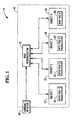
Fig. 1 , an exemplary illustration of anRFID system 10 comprises an RFID interrogator 15 (also referred to as an RFID tag reader or RFID reader),ambient noise 40, andmultiple objects RFID tag - Continuing with
Fig. 1 , theRFID interrogator 15 is designed to read the information from eachRFID tag range 45. TheRFID interrogator 15 reads information stored on an RFID tag by transmitting a radio frequency (RF) signal. This signal is referred to as a query signal or query command. The query signal is received by allRFID tags range 45 of theRFID interrogator 15. The RFID tags then transmit an RF reply signal that includes the information stored in the RFID tag. TheRFID interrogator 15 receives the RF reply signals from each RFID tag and recovers the information contained in each RF reply signal. The information may contain almost any type of data including a globally unique ID number, a price, tracking data, a destination, a part number, a serial number, or other attributes or combination of attributes that describe the object associated with the tag. Some RFID systems support RFID tags that contain relatively small amounts of information while other systems support RFID tags that contain large amounts of data and some support both types of tags. - To reduce cost, some types of RFID tags do not have an internal source of power, i.e., a battery, to drive the electronics of the tag. These types of tags are referred to as passive tags. A passive tag comprises an antenna connected to electronics, which usually consist of a single integrated circuit (IC). Passive tags are powered by the minute electrical current induced in the tag's antenna by an incoming RF signal transmitted by an RFID interrogator. The induced current provides a source of electrical energy that is suffient to power up the IC and to transmit a reply signal back to the RFID interrogator. Passive RFID tags generate a RF reply signal using a backscattering technique where the RF signal from the interrogator is modulated and reflected back to the RFID interrogator. Information stored in each tag is included in the RF reply signal. This transmission method reduces the power needed to operate a tag thus eliminating the need for a battery and reducing the cost of the tag. However, the RF signal transmitted by a passive tag is very weak.
- In the presence of
ambient RF noise 40, the RFID interrogator may fail to distinguish between RF reply signals from tags and theambient RF noise 40. When this occurs, theRFID interrogator 15 will fail to read one or more RFID tags. Additionally, the level ofambient RF noise 40 will vary over time and can cause intermittent failures and reliability issues. Most RFID environments have a detectible level ofambient RF noise 40 which can interfere with communications between theRFID interrogator 15 and the RFID tags. The source or sources of theambient RF noise 40 will vary and may physically reside inside or outside therange 45 of theRFID interrogator 15. In some environments, one or more powered transmitters, i.e., cell phones, cordless phones, WiFi systems (IEEE 802.11), or even other interrogators, contribute to the level of ambient RF noise. Ambient RF noise from these sources is relatively easy to identify and in some cases the system can be adapted to co-exist with these sources. However, in some environments, there exist one or more sources of the ambient RF noise where the ambient RF noise of interest is not detectable until after the interrogator transmits an RF signal. In some cases, the noise source is one or more non-transient RFID tags placed too close to the interrogator, which causes the tags to repeatedly respond to the interrogator. Protocol parameters can usually deal with the non-transient RFID tags by turning them off or otherwise preventing their participating in the process of querying transient RFID tags. In other cases, the source or sources are electro-mechanical devices that reflect or backscatter the interrogator's RF signal. Most of these devices were not specifically designed to transmit RF signals but nevertheless their design and mode of operation make it possible for them to reflect or backscatter an RF signal. In the absence of an RF signal to backscatter, these devices radiate little RF noise in the frequency band used by the RFID system. However, when the interrogator transmits an RF signal, these devices will reflect or backscatter the RF signal thus creating a source of ambient RF noise. Fans and florescent light ballasts are examples of electro-mechanical devices that display the characteristic of backscattering an RF signal. - Now referring to
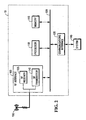
Fig. 2 , theinterrogator 15 is comprised of aprocessor 110 connected over abus 120 to: amemory 115, acommunications interface 125, and anRF interface 105. Thememory 115 contains both volatile and non-volatile types of memory. The non-volatile memory is used to store instructions that when executed by theprocessor 110, control the operation of theRFID interrogator 15. The non-volatile memory also contains parameters that are used by the instructions to control theRFID interrogator 15. In some embodiments, theprocessor 110 has the ability to change the contents of the non-volatile memory. In some embodiments, theprocessor 110 accesses the memory over a dedicated memory bus. Theprocessor 110 uses thecommunications interface 125 to communicate with one or moreexternal systems 145. The communications interface may be comprises of a wired interface such as Ethernet or a wireless interface such as Wi-Fi (IEEE 802.11). In some embodiments, one of the external systems is a point-of-sale terminal used in a retail environment. In some embodiments, one of the external systems includes a database that is used with information from the RFID tags to identify and track objects. - Continuing with
Fig. 2 , theprocessor 110 uses theRF Interface 105 to communicate with one or more RFID tags. TheRF interface 105 comprises anRF transmitter 140 and anRF receiver 135, both supporting multiple RF channels used to communicate with RFID tags. TheRF transmitter 140 and theRF receiver 135 are connected toantenna 130 and use theantenna 130 to transmit and receive signals to and from RFID tags. In some embodiments, multiple antennae are used to increase the range and ability to communicate with the RFID tags. Because a signal from a passive RFID tag is so weak, objects placed between the RFID tag and theantenna 130 act to shield and prevent the weak RF reply signal from reaching theantenna 130. An RFID system with more than one antenna increases the probability that the RF reply signal from an RFID tag will be received by at least one of the system's antennae. The additional antennae thus increase therange 45 and reliability of theRFID interrogator 15. - The
RFID interrogator 15 is limited to receiving only one RF reply signal, per RF channel, at a time. In a multi-tag environment where multiple RFID tags are inrange 45 of theRFID interrogator 15 at any given time, a collision occurs if more than one RFID tag replies at the same time. When a collision occurs, all data is lost because the signals are unintelligible. To prevent collisions, theRFID interrogator 15 must singulate each RFID tag within the RFID interrogator's 15range 45. Singulating an RFID tag occurs when theRFID interrogator 15 is able to identify and communicate with only one RFID tag at a time. The singulating process involves theRFID interrogator 15 setting and passing protocol parameters to all RFID tags withinrange 45. The RFID tags then use the parameters to determine the appropriate time and channel to use when communicating with theinterrogator 15. If the parameters are properly set, theinterrogator 15 will successfully singulate all RFID tags withinrange 45. If the parameters are not properly set, collisions will occur between RFID tags and singulation will take longer or may not occur at all. - EPCglobal Inc™ is an international organization that has established voluntary standards that govern certain aspects of an RFID system. One standard from this organization is the "EPC™ RadioFrequency Identity Protocols Class-1 Generation-2 UHF RFID Protocol for Communications at 860 MHz - 960 MHz, Version 1.0.9," includes guidelines for the operation of the RFID interrogator and tags. An interrogator that meets the requirements of this standard is described as a
class 1,generation 2 interrogator.RFID interrogator 15 complies with the standard for aclass 1,generation 2 interrogator although in other embodiments,RFID interrogator 15 will comply with other RFID standards that work with passive and/or active RFID tags. - The EPCglobal Inc™ standard for a
class 1,generation 2 RFID system defines a set of protocol parameters that govern the performance and accuracy of an RFID interrogator as it singulates RFID tags in an RFID system. The protocol parameters include: 1) "Q" which sets the number of slots in the round; 2) "DR" (TRcal divide ratio) sets the T=>R link frequency; 3) "SEL" chooses which Tags respond to the Query signal or command; 4) "SESSION" chooses a session for the inventory round; and 5) "TARGET" selects whether tags whose inventoried flag is A or B participate in the inventory round. The purpose of the protocol parameters is to eliminate multiple simultaneous tag responses (i.e., collisions) to a query signal from theRFID interrogator 15. The protocol parameters are broadcast to all tags within range of theinterrogator 15 during the query process. - The "Q" configurable protocol parameter identifies the number of time slots available for the tags to reply to a query signal. Each tag requires one time slot to reply to a query signal from the
interrogator 15. In a case where Q is set to 1, all tags within range of the interrogator will transmit their reply to a query signal in the same time slot. If multiple tags are in range of the interrogator, the tags will all transmit their reply in the same time slot and cause a collision. To prevent any possibility of a collision, Q could be set to the maximum value of 32,768 (215). This would prevent collisions but throughput performance of the RFID system would suffer greatly because it could take up to 32,768 time slots to singulate a tag. It is therefore desirable to use a smaller value for "Q" when the tag population is small and a larger "Q" value when the tag population is large to maximize throughput while reducing or eliminating collisions. - As shown above, when the protocol parameters are not properly set, a collision will occur when the
interrogator 15 fails to successfully singulate all the RFID tags causing more than one tag to respond at the same time, on the same RF channel. The EPCglobal Inc™ standard does not provide an intrinsic feature that will detect a collision; therefore theinterrogator 15 does not directly sense a collision or the presence of multiple tags during a collision. Additionally, a collision can be mistaken for a situation where there are no tags withinrange 45 of theinterrogator 15 when the query signal is transmitted, so theinterrogator 15 will have no reply signals to detect. Thus, an interrogator that implements theclass 1,generation 2 standard can not intrinsically distinguish between a collision that signifies the presence of multiple tags and the absence of a response that signifies no tags are present. - Architects of the standard sought to address the problems of system performance and distinguishing between no tags and multiple tags by suggesting that the interrogator use a default setting for the protocol parameters that force a predetermined minimum number of time slots. The presumption being that the minimum number of time slots will be large enough to allow some successful singulations to occur in a multi-tag environment but small enough so as not to adversely affect system performance. An algorithm is outlined in which a feedback loop is used to increase or decrease the number of time slots based upon the number of successful singulations. The algorithm states: 1) decrease the number of time slots (but not below the minimum number) if the number of successful singulations is equal to zero; 2) keep the number of time slots the same, if the number of successful singulations is equal to one; and 3) increase the number of time slots, if the number of successful singulations is greater than one. This algorithm would be continuously applied while the RFID system is operating.
- In addition to using the number of successful singulations to adjust the number of time slots, the architects of the standard sought to predict the occurrence of a collision between tags. While the
interrogator 15 cannot intrinsically detect a collision between two or more tags, the interrogator can compare the magnitude of a received signal to a threshold value and then predict whether a collision has occurred. The architects also defined a statistically calculated static threshold value for each RF channel used by theinterrogator 15. (The threshold value is sometimes referred to as a decision threshold.) Using this method, if a received signal exceeds the threshold value, a collision is assumed to have occurred. To prevent another collision, the number of time slots is increased. If the received signal falls below the threshold value, it is assumed that no collision has occurred. To improve system throughput performance, the number of time slots is decreased when there are no collisions but not below the minimum number. - This scheme is prone to errors because the statistically defined static threshold values cannot adapt to the dynamic nature of the ambient RF noise in an RFID environment. The level of
ambient RF noise 40 varies over time and by geographical location. To address this issue, the statistically defined static values are set relatively high. In environments that have periods of lowambient RF noise 40, the threshold values are too high causing theinterrogator 15 to miss a weak response from a tag at the edge of the interrogator's 15range 45. In this case, theinterrogator 15 falsely sees the weak response as noise. In environments that have periods of highambient RF noise 40, the threshold values are too low causing theinterrogator 15 to falsely identifyambient RF noise 40 as collisions. The false collisions will cause the RFID system to increase the number of time slots as it attempts to reduce the number of collisions. This causes intermittent problems that are difficult and expensive to diagnose. In environments that have a constant high level ofambient RF noise 40, the increase in collisions will adversely affect the performance of the RFID system and the interrogator's ability to read tags. - Referring now to
Fig. 3 , there is provided a block diagram that illustrates a method for dynamically adjusting the interrogator's 15 threshold values used to predict collisions. Theinterrogator 15 communicates with the RFID tags on a number of different radio frequencies or RF channels and a threshold value is maintained for each RF channel. Instep 300, theinterrogator 15 selects one of the RF channels supported by theRF receiver 135. In some embodiments, it is also possible to adjust the bandwidth of theRF receiver 135. In which case, the bandwidth is narrowed to increase the sensitivity of theRF receiver 135. Instep 305, theinterrogator 15 causes theRF transmitter 140 to transmit a brief signal. The brief signal will not cause RF tags to respond but will cause devices that are prone to reflect or backscatter an RF signal to do so. Instep 310, theinterrogator 15 causes theRF receiver 135 to capture a sample of the signal being received on the selected RF channel. This signal represents the instantaneous ambient RF noise for the selected RF channel. Theinterrogator 15 then performs a spectral analysis on the sampledsignal 315. This is accomplished in the frequency domain using Fourier analysis. However, other methods can be used to perform the same analysis. The spectral analysis produces a result that is the magnitude of the instantaneous ambient RF noise signal for the selected RF channel. Instep 320, theinterrogator 15 stores the result in a circular buffer that is dedicated to storing results for the selected RF channel. During idle periods, theinterrogator 15 continuously repeats this process for each RF channel. At some point, the circular buffers for each RF channel become full. At which time, the oldest result is removed and the newest result is added. The size of the circular buffer is selectable. - Concurrent with determining the magnitude of the instantaneous ambient RF noise for each RF channel, the
interrogator 15 calculates a dynamic threshold value for each channel by using the results stored in the circular buffer assigned to the RF channel. This is illustrated as follows. Instep 350, theinterrogator 15 selects a single RF channel. Instep 355, theinterrogator 15 reads all of the results from the circular buffer assigned to the selected RF channel. The ambient RF noise for the channel is modeled using a statistical Gaussian distribution, which has well known formulas to calculate the mean, variance, and standard deviation. Assuming the ambient noise will continue to follow a Gaussian distribution model, theinterrogator 15 sets the threshold value for the selected channel to the mean of the results from the circular buffer plus threestandard deviations 360. During idle periods, theinterrogator 15 periodically repeats this process for each channel. In this way, the threshold value for each channel is periodically updated and based on a statistical analysis of actual real-time ambient RF noise found on each RF channel. - Now referring to
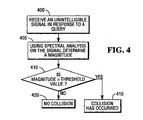
Fig. 4 , using a modified version of the above method for determining the instantaneous ambient RF noise on an RF channel and the threshold value for a RF channel, theinterrogator 15 can predict whether a collision has occurred. The method begins when theinterrogator 15 receives a signal in response to a query signal but the received signal is unintelligible (step 400). Theinterrogator 15 performs the spectral analysis on the received signal and determines a magnitude for the received signal (step 405). The magnitude is then compared to the threshold value for the RF channel used to receive the signal (step 410). Theinterrogator 15 concludes that a collision has occurred when the magnitude of the signal is greater than the threshold value (step 415). When the magnitude of the signal is less than the threshold, theinterrogator 15 concludes that no collision has occurred and that there are no tags are within range (step 420). - When a collision is predicted to have occurred, the
interrogator 15 adjusts the protocol parameters to increase the number of time slots in an effort to eliminate future collisions. Theinterrogator 15 then issues another query signal and checks the replies. This process is repeated until there are no collisions and all tags are read. Predicting collisions using dynamic threshold values is more accurate and dependable than using statistically defined static threshold values. Therefore, the use of conservative protocol parameters, that force a minimum number of time slots that adversely affects system throughput, is no longer required. The conservative protocol parameters were an additional safeguard that is only required when theinterrogator 15 is using statistically defined static threshold values. Therefore, using dynamic threshold values increases prediction accuracy and allows theinterrogator 15 to initially set the protocol parameters to as few as one time slot to maximize system throughput while still effectively handling collisions. - There are many sources of the instantaneous ambient RF noise and they will vary from one environment to another. The source or sources can be: other interrogators, a communication system operating nearby (i.e., WiFi or cellular), spurious emissions from electronic equipment, a device that reflects or backscatters RF signals, or a combination of sources. Whatever the source, the use of dynamic threshold values by the
interrogator 15 will allow the RFID system to dynamically adapt to the current environment so as to maintain maximum throughput and reliability. - It should also be appreciated that an RFID system using active RFID tags (tags that use batteries to power the electronics and RF transmitter) or a combination of active and passive RFID tags will have the same benefits as the above RFID system.
- While the present invention is disclosed in the context of a presently preferred embodiment, it will be recognized that a wide variety of implementations may be employed by persons of ordinary skill in the art consistent with the above discussion, the drawings, and the claims that follow below.
Claims (11)
- A method of optimising a radio frequency interrogator (15) comprising the steps of:transmitting a first radio frequency signal on a radio frequency channel;receiving a second radio frequency signal within the radio frequency channel;performing spectral analysis on the received second signal to obtain a result;characterised in that
the first radio frequency signal does not cause a radio frequency tag (50) to respond thereto;
the second radio frequency signal is a backscattered portion of the first radio frequency signal which is indicative of the ambient noise present on the radio frequency channel; and
setting the number of time slots available for singulations on the radio frequency channel based on a statistical analysis that uses the result of the spectral analysis. - A method according to claim 1, wherein the result produced by the spectral analysis is the magnitude of the received signal.
- A method according to either claim 1 or claim 2, wherein the spectral analysis comprises a Fourier analysis of the received signal.
- A method according to any preceding claim, wherein the result is stored in a circular buffer assigned to the radio frequency channel.
- A method according to claim 4, wherein the statistical analysis includes using a Gaussian distribution model on data stored in the circular buffer.
- A radio frequency interrogator (15) comprising:a radio frequency transmitter (140) adapted to transmit radio frequency signals on one or more radio frequency channels;a radio frequency receiver (135) adapted to receive radio frequency signals on one or more radio frequency channels;a processing unit (110) in communication with the receiver and the transmitter; anda memory unit (115) electrically coupled to the processing unit (110), wherein the memory unit (115) has stored therein a plurality of instructions which, when executed by the processing unit (110) cause the processing unit (110) to;characterised in thati) select a radio frequency channel;ii) cause the transmitter (140) to transmit a first radio frequency signal on the radio frequency channel;iii) receive from the receiver (135) a second radio frequency signal on the radio frequency channel;iv) perform a spectral analysis on the received signal to obtain a result;
the first radio frequency signal does not cause a radio frequency tag (50) to respond thereto;
the second radio frequency signal is a backscattered portion of the first radio frequency signal which is indicative of the ambient noise (40) present on the radio frequency channel; and
the processor (110) being adapted to set the number of time slots available for singulations on the radio frequency channel based on a statistical analysis that uses the result of the spectral analysis. - An interrogator according to claim 6, wherein the result provided by the spectral analysis is the magnitude of the second radio frequency signal.
- An interrogator according to either claim 6 or claim 7, wherein the spectral analysis comprises a Fourier analysis of the second radio frequency signal.
- An interrogator according to any one of claims 6 to 8, wherein the bandwidth of the receiver (135) is narrowed prior to receiving the second radio frequency signal.
- An interrogator according to any one of claims 6 to 9, wherein the result is stored in a circular buffer assigned to the radio frequency channel.
- An interrogator according to claim 10, wherein the statistical analysis includes using a Gaussian distribution model on data stored in the circular buffer.
Applications Claiming Priority (1)
| Application Number | Priority Date | Filing Date | Title |
|---|---|---|---|
| US11/557,544 US7649441B2 (en) | 2006-11-08 | 2006-11-08 | Method and system for tuning an RFID interrogator |
Publications (2)
| Publication Number | Publication Date |
|---|---|
| EP1923816A1 EP1923816A1 (en) | 2008-05-21 |
| EP1923816B1 true EP1923816B1 (en) | 2010-09-15 |
Family
ID=39086131
Family Applications (1)
| Application Number | Title | Priority Date | Filing Date |
|---|---|---|---|
| EP07253985A Active EP1923816B1 (en) | 2006-11-08 | 2007-10-09 | Method and system for tuning an RFID interrogator |
Country Status (5)
| Country | Link |
|---|---|
| US (1) | US7649441B2 (en) |
| EP (1) | EP1923816B1 (en) |
| JP (1) | JP5121048B2 (en) |
| CN (1) | CN101178765B (en) |
| DE (1) | DE602007009169D1 (en) |
Families Citing this family (32)
| Publication number | Priority date | Publication date | Assignee | Title |
|---|---|---|---|---|
| JP4681649B2 (en) * | 2005-08-25 | 2011-05-11 | エヌエックスピー ビー ヴィ | RFID reader and evaluation method for data stream signal evaluation |
| KR101396430B1 (en) * | 2007-10-31 | 2014-05-20 | 삼성전자주식회사 | Apparatus and method for anti-collision tag in radio frequency identification system |
| KR100922393B1 (en) * | 2007-11-23 | 2009-10-19 | 성균관대학교산학협력단 | Tag estimation method and tag identification method for rfid system |
| KR101536696B1 (en) * | 2009-02-02 | 2015-07-14 | 삼성전자주식회사 | RFID(Radio Frequency IDentification) Interrogator |
| US8310344B2 (en) * | 2009-02-19 | 2012-11-13 | FP Wireless, LLC | Long range radio frequency identification system |
| KR100914850B1 (en) * | 2009-03-27 | 2009-09-02 | 주식회사 아이디로 | Back scattering type rfid communication system |
| US8249512B2 (en) | 2010-06-18 | 2012-08-21 | At&T Mobility Ii Llc | Assessing interference environment for wireless communication devices |
| JP2012194696A (en) * | 2011-03-15 | 2012-10-11 | Omron Corp | Rfid reader/writer, rfid system, and communication method |
| EP2804127A1 (en) | 2013-05-16 | 2014-11-19 | ST-Ericsson SA | A Near Field Communication Technology Type B Reader Device And A Reader Implemented Method Of Resolving Multiple NFC B Listen Devices |
| US9715005B2 (en) | 2013-06-06 | 2017-07-25 | Zih Corp. | Method, apparatus, and computer program product improving real time location systems with multiple location technologies |
| US11423464B2 (en) | 2013-06-06 | 2022-08-23 | Zebra Technologies Corporation | Method, apparatus, and computer program product for enhancement of fan experience based on location data |
| US9985672B2 (en) | 2013-06-06 | 2018-05-29 | Zih Corp. | Method, apparatus, and computer program product for evaluating performance based on real-time data for proximity and movement of objects |
| US10609762B2 (en) | 2013-06-06 | 2020-03-31 | Zebra Technologies Corporation | Method, apparatus, and computer program product improving backhaul of sensor and other data to real time location system network |
| US9517417B2 (en) | 2013-06-06 | 2016-12-13 | Zih Corp. | Method, apparatus, and computer program product for performance analytics determining participant statistical data and game status data |
| US10437658B2 (en) | 2013-06-06 | 2019-10-08 | Zebra Technologies Corporation | Method, apparatus, and computer program product for collecting and displaying sporting event data based on real time data for proximity and movement of objects |
| US9699278B2 (en) | 2013-06-06 | 2017-07-04 | Zih Corp. | Modular location tag for a real time location system network |
| US9668164B2 (en) * | 2014-06-05 | 2017-05-30 | Zih Corp. | Receiver processor for bandwidth management of a multiple receiver real-time location system (RTLS) |
| US9626616B2 (en) | 2014-06-05 | 2017-04-18 | Zih Corp. | Low-profile real-time location system tag |
| GB2542298B (en) | 2014-06-05 | 2021-01-20 | Zebra Tech Corp | Method for iterative target location in a multiple receiver target location system |
| WO2015186044A1 (en) | 2014-06-05 | 2015-12-10 | Zih Corp. | Receiver processor for adaptive windowing and high-resolution toa determination in a multiple receiver target location system |
| DE112015002651B4 (en) | 2014-06-05 | 2023-02-16 | Zebra Technologies Corporation | Systems, apparatus and methods for variable rate ultra wideband communications |
| US9661455B2 (en) | 2014-06-05 | 2017-05-23 | Zih Corp. | Method, apparatus, and computer program product for real time location system referencing in physically and radio frequency challenged environments |
| US20150375083A1 (en) | 2014-06-05 | 2015-12-31 | Zih Corp. | Method, Apparatus, And Computer Program Product For Enhancement Of Event Visualizations Based On Location Data |
| CN113050031A (en) | 2014-06-06 | 2021-06-29 | 斑马技术公司 | Method, apparatus and computer program product for improving a real-time location system utilizing multiple location technologies |
| US9759803B2 (en) | 2014-06-06 | 2017-09-12 | Zih Corp. | Method, apparatus, and computer program product for employing a spatial association model in a real time location system |
| EP3009956B1 (en) | 2014-10-13 | 2016-09-14 | Sick Ag | Method for detecting whether a transponder of an RFID system is in a boundary area, RFID system and safety switch |
| KR20240038123A (en) * | 2015-05-06 | 2024-03-22 | 크라운 이큅먼트 코포레이션 | Diagnostic tag for an industrial vehicle tag reader |
| CN105303137B (en) * | 2015-10-29 | 2018-06-26 | 北京交通大学 | A kind of determining method of the threshold value of the reader of environment backscatter system |
| US10243254B2 (en) | 2016-08-25 | 2019-03-26 | Schlage Lock Company Llc | Self adjusting antenna impedance for credential detection in an access control system |
| TWI765193B (en) * | 2019-11-19 | 2022-05-21 | 宇力電通數位整合有限公司 | Signal transmission system, client apparatus and signal detection method thereof |
| EP3945449A1 (en) * | 2020-07-27 | 2022-02-02 | Nxp B.V. | Rfid transponder having modifiable settings |
| JP7024035B1 (en) * | 2020-10-26 | 2022-02-22 | 株式会社京三製作所 | On-board equipment |
Family Cites Families (13)
| Publication number | Priority date | Publication date | Assignee | Title |
|---|---|---|---|---|
| JPH0983585A (en) * | 1995-09-19 | 1997-03-28 | Tokimec Inc | Data storage medium, data reader and data reading method |
| US6130894A (en) * | 1998-03-09 | 2000-10-10 | Broadcom Homenetworking, Inc. | Off-line broadband network interface |
| US6452980B1 (en) * | 2000-01-10 | 2002-09-17 | Sarnoff Corporation | Encoding/decoding system for coherent signal interference reduction |
| JP4352641B2 (en) * | 2001-07-11 | 2009-10-28 | 株式会社デンソー | Tag reader |
| JP2003288554A (en) * | 2002-03-27 | 2003-10-10 | Anritsu Corp | Non-contact ic card reader |
| JP4019994B2 (en) * | 2003-03-31 | 2007-12-12 | ブラザー工業株式会社 | Communication system, interrogator and responder included therein |
| US6970518B2 (en) * | 2003-03-11 | 2005-11-29 | Motorola, Inc. | Method and apparatus for electronic item identification in a communication system using known source parameters |
| US7218641B2 (en) * | 2003-03-11 | 2007-05-15 | Motorola, Inc. | Method and apparatus for adaptive processing gain for multiple source devices in a communications system |
| JP4367207B2 (en) * | 2004-04-02 | 2009-11-18 | ソニー株式会社 | Information processing apparatus, wireless communication system, and wireless communication method |
| JP4257277B2 (en) * | 2004-08-25 | 2009-04-22 | 株式会社東芝 | Wireless tag device, tag identification device, and wireless communication system |
| JP2006170816A (en) * | 2004-12-16 | 2006-06-29 | Mitsubishi Electric Corp | Pulse specifications detection circuit |
| JP2006197232A (en) * | 2005-01-13 | 2006-07-27 | Mitsubishi Electric Corp | Transmission power controller |
| JP4681649B2 (en) | 2005-08-25 | 2011-05-11 | エヌエックスピー ビー ヴィ | RFID reader and evaluation method for data stream signal evaluation |
-
2006
- 2006-11-08 US US11/557,544 patent/US7649441B2/en active Active
-
2007
- 2007-10-09 DE DE602007009169T patent/DE602007009169D1/en active Active
- 2007-10-09 EP EP07253985A patent/EP1923816B1/en active Active
- 2007-10-31 CN CN200710167083.3A patent/CN101178765B/en active Active
- 2007-11-07 JP JP2007289526A patent/JP5121048B2/en active Active
Also Published As
| Publication number | Publication date |
|---|---|
| US7649441B2 (en) | 2010-01-19 |
| JP2008125077A (en) | 2008-05-29 |
| CN101178765B (en) | 2015-02-11 |
| JP5121048B2 (en) | 2013-01-16 |
| EP1923816A1 (en) | 2008-05-21 |
| CN101178765A (en) | 2008-05-14 |
| US20080106381A1 (en) | 2008-05-08 |
| DE602007009169D1 (en) | 2010-10-28 |
Similar Documents
| Publication | Publication Date | Title |
|---|---|---|
| EP1923816B1 (en) | Method and system for tuning an RFID interrogator | |
| EP1923815B1 (en) | Method and system for tuning an RFID interrogator | |
| US10248817B2 (en) | Reading RFID tags in defined spatial locations | |
| US8537014B2 (en) | RFID tag movement determination | |
| US8519823B2 (en) | Radio frequency identification (RFID) tag location systems and methods | |
| EP3214574B1 (en) | Encoded information reading terminal with locate functionality | |
| EP2471021B1 (en) | Rfid portal system with rfid tags having various read ranges | |
| US11107034B1 (en) | Portal monitoring with steered-beam RFID systems | |
| US20100148933A1 (en) | Inclusive or Exclusive RFID Tag Interrogation and Query Round | |
| US20070273481A1 (en) | RFID tag with programmable read range | |
| US20060232384A1 (en) | Radio frequency identification reader, radio frequency identification tag, and system and method for identifying tag using bit synchronizing signal | |
| US8698600B2 (en) | Method and circuit for accessing RFID tag | |
| Bolić et al. | Performance of passive UHF RFID systems in practice | |
| US20190019073A1 (en) | Radio tag reading device and radio tag reading method | |
| JP5099622B2 (en) | Reader test apparatus and reader test system | |
| EP2620895B1 (en) | System for managing RFID tags | |
| US20090153319A1 (en) | RFID Reader/Interrogator Sub-Band Selection |
Legal Events
| Date | Code | Title | Description |
|---|---|---|---|
| PUAI | Public reference made under article 153(3) epc to a published international application that has entered the european phase |
Free format text: ORIGINAL CODE: 0009012 |
|
| AK | Designated contracting states |
Kind code of ref document: A1 Designated state(s): AT BE BG CH CY CZ DE DK EE ES FI FR GB GR HU IE IS IT LI LT LU LV MC MT NL PL PT RO SE SI SK TR |
|
| AX | Request for extension of the european patent |
Extension state: AL BA HR MK RS |
|
| 17P | Request for examination filed |
Effective date: 20081121 |
|
| 17Q | First examination report despatched |
Effective date: 20081222 |
|
| AKX | Designation fees paid |
Designated state(s): DE FR GB |
|
| RAP1 | Party data changed (applicant data changed or rights of an application transferred) |
Owner name: NCR CORPORATION |
|
| GRAP | Despatch of communication of intention to grant a patent |
Free format text: ORIGINAL CODE: EPIDOSNIGR1 |
|
| GRAS | Grant fee paid |
Free format text: ORIGINAL CODE: EPIDOSNIGR3 |
|
| GRAA | (expected) grant |
Free format text: ORIGINAL CODE: 0009210 |
|
| AK | Designated contracting states |
Kind code of ref document: B1 Designated state(s): DE FR GB |
|
| REG | Reference to a national code |
Ref country code: GB Ref legal event code: FG4D |
|
| REG | Reference to a national code |
Ref country code: GB Ref legal event code: 746 Effective date: 20100928 |
|
| REF | Corresponds to: |
Ref document number: 602007009169 Country of ref document: DE Date of ref document: 20101028 Kind code of ref document: P |
|
| PLBE | No opposition filed within time limit |
Free format text: ORIGINAL CODE: 0009261 |
|
| STAA | Information on the status of an ep patent application or granted ep patent |
Free format text: STATUS: NO OPPOSITION FILED WITHIN TIME LIMIT |
|
| 26N | No opposition filed |
Effective date: 20110616 |
|
| REG | Reference to a national code |
Ref country code: DE Ref legal event code: R097 Ref document number: 602007009169 Country of ref document: DE Effective date: 20110616 |
|
| REG | Reference to a national code |
Ref country code: FR Ref legal event code: PLFP Year of fee payment: 9 |
|
| REG | Reference to a national code |
Ref country code: FR Ref legal event code: PLFP Year of fee payment: 10 |
|
| REG | Reference to a national code |
Ref country code: FR Ref legal event code: PLFP Year of fee payment: 11 |
|
| REG | Reference to a national code |
Ref country code: FR Ref legal event code: PLFP Year of fee payment: 12 |
|
| REG | Reference to a national code |
Ref country code: DE Ref legal event code: R081 Ref document number: 602007009169 Country of ref document: DE Owner name: NCR VOYIX CORP., ATLANTA, US Free format text: FORMER OWNER: NCR CORP., DULUTH, GA., US Ref country code: DE Ref legal event code: R082 Ref document number: 602007009169 Country of ref document: DE Representative=s name: V. BEZOLD & PARTNER PATENTANWAELTE - PARTG MBB, DE Ref country code: DE Ref legal event code: R081 Ref document number: 602007009169 Country of ref document: DE Owner name: NCR CORPORATION, ATLANTA, US Free format text: FORMER OWNER: NCR CORP., DULUTH, GA., US |
|
| P01 | Opt-out of the competence of the unified patent court (upc) registered |
Effective date: 20230505 |
|
| PGFP | Annual fee paid to national office [announced via postgrant information from national office to epo] |
Ref country code: GB Payment date: 20231027 Year of fee payment: 17 |
|
| PGFP | Annual fee paid to national office [announced via postgrant information from national office to epo] |
Ref country code: FR Payment date: 20231025 Year of fee payment: 17 Ref country code: DE Payment date: 20231027 Year of fee payment: 17 |
|
| REG | Reference to a national code |
Ref country code: DE Ref legal event code: R081 Ref document number: 602007009169 Country of ref document: DE Owner name: NCR VOYIX CORP., ATLANTA, US Free format text: FORMER OWNER: NCR CORPORATION, ATLANTA, GA, US |