EP1914137A2 - Trailer brake valve for trailer vehicles with electronic brake control and increased security of the parked trailer - Google Patents
Trailer brake valve for trailer vehicles with electronic brake control and increased security of the parked trailer Download PDFInfo
- Publication number
- EP1914137A2 EP1914137A2 EP08002081A EP08002081A EP1914137A2 EP 1914137 A2 EP1914137 A2 EP 1914137A2 EP 08002081 A EP08002081 A EP 08002081A EP 08002081 A EP08002081 A EP 08002081A EP 1914137 A2 EP1914137 A2 EP 1914137A2
- Authority
- EP
- European Patent Office
- Prior art keywords
- valve
- pressure
- brake
- trailer
- connection
- Prior art date
- Legal status (The legal status is an assumption and is not a legal conclusion. Google has not performed a legal analysis and makes no representation as to the accuracy of the status listed.)
- Withdrawn
Links
Images


Classifications
-
- B—PERFORMING OPERATIONS; TRANSPORTING
- B60—VEHICLES IN GENERAL
- B60T—VEHICLE BRAKE CONTROL SYSTEMS OR PARTS THEREOF; BRAKE CONTROL SYSTEMS OR PARTS THEREOF, IN GENERAL; ARRANGEMENT OF BRAKING ELEMENTS ON VEHICLES IN GENERAL; PORTABLE DEVICES FOR PREVENTING UNWANTED MOVEMENT OF VEHICLES; VEHICLE MODIFICATIONS TO FACILITATE COOLING OF BRAKES
- B60T15/00—Construction arrangement, or operation of valves incorporated in power brake systems and not covered by groups B60T11/00 or B60T13/00
- B60T15/02—Application and release valves
- B60T15/025—Electrically controlled valves
- B60T15/027—Electrically controlled valves in pneumatic systems
-
- B—PERFORMING OPERATIONS; TRANSPORTING
- B60—VEHICLES IN GENERAL
- B60T—VEHICLE BRAKE CONTROL SYSTEMS OR PARTS THEREOF; BRAKE CONTROL SYSTEMS OR PARTS THEREOF, IN GENERAL; ARRANGEMENT OF BRAKING ELEMENTS ON VEHICLES IN GENERAL; PORTABLE DEVICES FOR PREVENTING UNWANTED MOVEMENT OF VEHICLES; VEHICLE MODIFICATIONS TO FACILITATE COOLING OF BRAKES
- B60T15/00—Construction arrangement, or operation of valves incorporated in power brake systems and not covered by groups B60T11/00 or B60T13/00
- B60T15/02—Application and release valves
- B60T15/18—Triple or other relay valves which allow step-wise application or release and which are actuated by brake-pipe pressure variation to connect brake cylinders or equivalent to compressed air or vacuum source or atmosphere
- B60T15/24—Triple or other relay valves which allow step-wise application or release and which are actuated by brake-pipe pressure variation to connect brake cylinders or equivalent to compressed air or vacuum source or atmosphere controlled by three fluid pressures
- B60T15/243—Trailer control valves
-
- B—PERFORMING OPERATIONS; TRANSPORTING
- B60—VEHICLES IN GENERAL
- B60T—VEHICLE BRAKE CONTROL SYSTEMS OR PARTS THEREOF; BRAKE CONTROL SYSTEMS OR PARTS THEREOF, IN GENERAL; ARRANGEMENT OF BRAKING ELEMENTS ON VEHICLES IN GENERAL; PORTABLE DEVICES FOR PREVENTING UNWANTED MOVEMENT OF VEHICLES; VEHICLE MODIFICATIONS TO FACILITATE COOLING OF BRAKES
- B60T8/00—Arrangements for adjusting wheel-braking force to meet varying vehicular or ground-surface conditions, e.g. limiting or varying distribution of braking force
- B60T8/32—Arrangements for adjusting wheel-braking force to meet varying vehicular or ground-surface conditions, e.g. limiting or varying distribution of braking force responsive to a speed condition, e.g. acceleration or deceleration
- B60T8/321—Arrangements for adjusting wheel-braking force to meet varying vehicular or ground-surface conditions, e.g. limiting or varying distribution of braking force responsive to a speed condition, e.g. acceleration or deceleration deceleration
- B60T8/323—Systems specially adapted for tractor-trailer combinations
-
- B—PERFORMING OPERATIONS; TRANSPORTING
- B60—VEHICLES IN GENERAL
- B60T—VEHICLE BRAKE CONTROL SYSTEMS OR PARTS THEREOF; BRAKE CONTROL SYSTEMS OR PARTS THEREOF, IN GENERAL; ARRANGEMENT OF BRAKING ELEMENTS ON VEHICLES IN GENERAL; PORTABLE DEVICES FOR PREVENTING UNWANTED MOVEMENT OF VEHICLES; VEHICLE MODIFICATIONS TO FACILITATE COOLING OF BRAKES
- B60T8/00—Arrangements for adjusting wheel-braking force to meet varying vehicular or ground-surface conditions, e.g. limiting or varying distribution of braking force
- B60T8/32—Arrangements for adjusting wheel-braking force to meet varying vehicular or ground-surface conditions, e.g. limiting or varying distribution of braking force responsive to a speed condition, e.g. acceleration or deceleration
- B60T8/321—Arrangements for adjusting wheel-braking force to meet varying vehicular or ground-surface conditions, e.g. limiting or varying distribution of braking force responsive to a speed condition, e.g. acceleration or deceleration deceleration
- B60T8/3255—Systems in which the braking action is dependent on brake pedal data
- B60T8/327—Pneumatic systems
-
- B—PERFORMING OPERATIONS; TRANSPORTING
- B60—VEHICLES IN GENERAL
- B60T—VEHICLE BRAKE CONTROL SYSTEMS OR PARTS THEREOF; BRAKE CONTROL SYSTEMS OR PARTS THEREOF, IN GENERAL; ARRANGEMENT OF BRAKING ELEMENTS ON VEHICLES IN GENERAL; PORTABLE DEVICES FOR PREVENTING UNWANTED MOVEMENT OF VEHICLES; VEHICLE MODIFICATIONS TO FACILITATE COOLING OF BRAKES
- B60T8/00—Arrangements for adjusting wheel-braking force to meet varying vehicular or ground-surface conditions, e.g. limiting or varying distribution of braking force
- B60T8/32—Arrangements for adjusting wheel-braking force to meet varying vehicular or ground-surface conditions, e.g. limiting or varying distribution of braking force responsive to a speed condition, e.g. acceleration or deceleration
- B60T8/34—Arrangements for adjusting wheel-braking force to meet varying vehicular or ground-surface conditions, e.g. limiting or varying distribution of braking force responsive to a speed condition, e.g. acceleration or deceleration having a fluid pressure regulator responsive to a speed condition
- B60T8/349—Systems adapted to control a set of axles, e.g. tandem axles
Definitions
- Such a trailer brake valve is out of DE 28 10 850 A1 known.
- the breakaway protection for the coupling hose "supply” is implemented; if the connection for the supply air [there automatic brake connection (20)] is depressurized, then the emergency brake piston [there (22)] becomes depressurized on its upper side and that on its Bottom adjoining reservoir pressure pushes it up so that first the exhaust valve [there (26, 28)] closes and in the further upward movement, the inlet valve [there (26, 27)] is opened, so that the at the reservoir terminal [there ( 33)] is also transmitted pressure in the brake chamber and rests against the brake cylinder connections.
- the function of an overfeed of the brake pressure transmitted to the brake cylinder is further integrated with respect to the pneumatic brake signal.
- a load-dependent regulated dual-line trailer brake system which consists of a valve designed as a seat valve emergency brake valve [there (3)] and a load-dependent controlled brake force controller there (5)], this as a combination of a load-dependent acting control part with an air flow intensifying Relay valve is formed.
- the emergency brake valve corresponds in its operation of the tear function in a conventional trailer brake valve, so that the function of both valves can be understood as the function of a trailer brake valve with load-controlled braking force control mutatis mutandis. This is especially true, as well as a trailer brake valve z. B.
- the parking and maneuvering modes of the parking and maneuvering valves namely, "parking", “driving” and “maneuvering” are preselected by only one control knob provided with an operation knob [there (7)], which is for Control of the respective operating mode can take three switching positions.
- Another difference of the parking and maneuvering valve to the combination trailer brake valve / combination release valve is that when parking as well as while driving in a supply line demolition [or dissolved supply clutch] not the service brake but the parking brake takes effect.
- a supply line demolition or dissolved supply clutch
- the double release valve [there (1) under "Diagram with ALB trailer brake valve”] consists of a service brake release valve [in Fig. 1 (33)], a parking valve [in Fig. 1 (20)] and a check valve associated with the parking valve.
- the service brake release valve is pneumatic on the input side [there (1-1)] with the supply coupling head [in Fig. 1 (48)] and on the output side pneumatically connected to the supply pressure connection [there (1) of the local ALB trailer brake valve (2), in FIG Fig. 1 (1) of the trailer brake valve (8)] connected.
- the service brake release valve In its driving position [pulled position of the local black operating knob], the service brake release valve has no effect on the pressure in the service brake chambers of the spring brake cylinder; in its release position [not pulled position of the black actuating button], the service brake release valve causes the release of the service brakes.
- the service brake release valve is used to move a decoupled trailer by overriding the automatic brake [triggered by the supply line breakaway in the trailer brake valve]; This happens because in the release position tank pressure is deflected and fed to the supply connection in the trailer brake valve [in Fig. 1 from the release connection (5) via the pressure channel (24) to the supply connection (1)]; By this pressure deflection is simulated in the trailer brake valve that is applied to the coupling head for the supply pressure hose pressure.
- the parking valve vented in its parking position - [pulled position of the local red actuator button] the release chambers of the spring brake cylinders, so that the parking brakes are effective; In its driving position [not pulled position of the red actuating button], the parking valve releases the parking brakes by ventilating the spring-loaded release chambers.
- This well-known law prescribed function of the check valve is also effective in a parked trailer, which by uncoupling in the automatic Brake function goes and in which the parking valve remains in the driving position.
- a brake pressure modulator For the generation of the brake pressure, a brake pressure modulator is provided, which consists of electrically controllable valves, which are usually controlled in clocking mode of operation of the brake control electronics and serve as pilot valves for generating a control pressure in the control chamber of a relay valve, which air mass amplifies the control pressure as a brake pressure on its output to one or more brake cylinders; In this case, one or more brake control channels constructed in this way can be implemented.
- a trailer brake valve for use in a trailer with electronic brake control therefore needs neither the function of the air quantity gain nor special functions such.
- For such a trailer brake valve it is quite sufficient if the basic functions, namely the provision of the transmitted braking force from the towing vehicle, the anti-tamper and the possibility of connection of a double-release valve explained above are realized.
- the invention is therefore the object of a trailer brake valve after the former known
- the invention has the advantage that no additional components or piping are required for increased safety against unintentional rolling on the trailer side.
- the invention has the advantage that the susceptibility to errors is significantly reduced by the significantly simplified compared to the prior art construction.
- Relay valves are not free from air consumption due to the venting of the relay valve pressure chamber.
- the relay valve principle working valve device according to the invention has the advantage that no more air consumption takes place and associated with an air consumption noise also does not take place.
- a development of the invention has the advantage that by eliminating the relay valve with its time delay "output input" of i. Gen. more than 30 ms, a time advantage for the electrical signal of the pressure sensor is connected, because this pressure sensor measures the output from the trailer brake valve brake pressure.
- the pneumatic path is optimized, because this is provided in contrast to the normally effective electrical brake signal transmission only for emergency braking, in which can be dispensed with a load-dependent brake pressure influencing.
- the optimized pneumatic path has the advantage that on the one hand accounts air-consuming facilities and on the other time delays caused by such facilities no longer occur.
- Another development of the invention has the advantage that the switching of the trailer brake valve in the tear-off position depends only on the supply port of the valve [this is pneumatically connected to the red coupling head] applied pressure. The transition from one to the other switching position also takes place abruptly, so that the switching is also independent of friction and creeping transitions are avoided.
- the emergency braking "immediately", and it must be compared with conventional solutions initially no characteristic traversed.
- the valve is designed as a pressure compensated positive overlap valve; Compared to conventional solutions, this development also has the advantage that breathing spaces and the associated risk of icing are avoided.
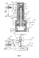
- Fig. 1 Based on Fig. 1 the functional scope of the trailer brake valve for a trailer EBS brake system will be explained; In this case, it will be explained on the basis of the realization, in which way already mentioned functions that can be omitted, are taken over by the trailer EBS brake pressure control.
- FIG. 1 The block diagram after Fig. 1 it is based on the configuration of a base variant for trailer EBS systems, which consists of a semi-trailer (34) with two axles, this is a 2S / 2M system [two ABS sensors for two wheels and two Modulator channels for the wheel brakes the left and the right side]; the ABS brake pressure control is thus carried out page by page.
- a base variant for trailer EBS systems which consists of a semi-trailer (34) with two axles, this is a 2S / 2M system [two ABS sensors for two wheels and two Modulator channels for the wheel brakes the left and the right side]; the ABS brake pressure control is thus carried out page by page.
- a supply pressure hose for transmitting the supply pressure [attached to the towing vehicle red pressure hose, which is coupled via the "red coupling head" (48) of the trailer]
- a brake pressure hose (31) for transmitting the brake pressure [tractor-mounted yellow wire coupled via the trailer's yellow coupling head (49)].
- a trailer control valve [AST valve].
- the supply pressure hose (30) is pneumatically connected via the above-described service brake release valve (33) to the supply port (1), and the brake pressure hose (31) via a pneumatic line to the brake specification port (4) of the trailer brake valve (8) ,
- the trailer brake valve (8) further has a container port (3) to which the reservoir pressure vessel (9) is connected for the trailer, and a brake pressure port (2), at which the pneumatic brake pressure to the pneumatic input (28) of the pneumatic Bremstikmodulators (29) is output;
- This brake pressure represents the redundant pressure for the trailer with its electronic brake pressure control.
- the redundancy pressure in the trailer in case of failure is used for braking, namely, when the motor vehicle electronics has failed.
- the "redundancy pressure" in the trailer is used to brake the trailer at all, since such a motor vehicle, the electronic brake pressure control in the trailer can not respond.
- the implementation of the pneumatic brake signal in an electronic signal is carried out by the pressure sensor (47) in the trailer.
- the trailer brake valve (8) also controls a full brake pressure to the modulator (29), which allows purely pneumatic braking without the intervention of the electronics.
- the tank connection (3) is pneumatically connected to the brake pressure port (2).
- the trailer brake valve (8) at the brake pressure port (2) outputs a pressure, either the redundant pressure or the reservoir pressure which is supplied to the pneumatic brake pressure modulator (29).
- the brake pressure modulator (29) further has a pressure supply port (35) which is connected by a pneumatic line to the supply pressure vessel (9).
- the brake pressure modulator (29) is controlled by electrical connections through the electronics unit (42).
- the relay valve working ports [there (20) and (22) and (21) and (23)], respectively, are as in Fig.
- the pneumatic input (28) is connected to the control pressure port [there (13)] and the pressure supply port (35) is connected to the supply pressure port [there (17)] of the pressure control module after the S1.
- the 3/2-solenoid valve [there (12)] of the S1 at the pneumatic input (28) after Fig. 1 incoming pressure to the control inputs of the relay valves [there (3), (4)] of the S1 controlled by and air-massed output at said relay valve working ports.
- This mode of operation corresponds to the case of redundancy in which a pneumatic redundancy pressure is fed to the brake cylinder in an air-volume-boosted manner without the electronic unit (42) being involved in any way.
- the electronic unit (42) also uses the pressure measurement value of the pressure sensor (47) for the EBS brake pressure control, which represents the brake pressure of the trailer brake valve (8) output at the brake pressure connection (2).
- This pressure reading is provided in the case of a conventional towing vehicle in which the electronics unit (42) uses the electrical pressure reading as the EBS brake pressure control electrical brake request signal.
- ABS brake control is also performed by the EBS brake pressure control devices; this is on the left and right wheels, which are braked by the spring brake cylinders [(38) and (39) and (40) and (41)], provided corresponding ABS sensors for detecting the respective wheel speeds.
- the trailer brake valve includes connection options for the function modules of the double release valve, d. H. the connection of the service brake release valve (33) and the parking valve (20).
- Fig. 1 the trailer brake valve (8) is shown in its valve home position, which can be seen that the red coupling head (48) is drawn in the coupled state.
- connection of the service brake release valve (33) of the above-mentioned release connection (5) is provided, which is connected by a trailer in the control valve (8) existing direct pneumatic connection with the container port (3).
- connection of the parking valve (20) to the trailer brake valve (8) does not take place as in the St. d. T. via the reservoir, but via a separate parking terminal (21); within the trailer brake valve (8), the parking connection (21) is opened via the already mentioned above, in the direction of the parking connection (21), first check valve (19) connected to the container port (3) [this check valve is, as explained above, housed in St.DT in the parking valve of the double release valve].
- parking valve (20) is applied to the park outlet (21) tank pressure via the pressure channel (23) through the parking valve port (51) in the release line (53) and transmitted from there via the Brake overload shuttle valve (52) and the spring-loaded release lines (50) fed into the release chambers for the spring brake cylinders (38, 39, 40, 41); thus the parking brakes of this spring brake cylinder are released.
- a bypass channel (46) is provided in the trailer brake valve (8) parallel to the first check valve (19) in the trailer brake valve (21), which is irrelevant in the valve basic position of the trailer brake valve (8) since it has effective paths in this switching state (54) is completed.
- valve breakaway position In the valve breakaway position, however, the paths of the valve breakaway position (55) become effective and in this position the tank pressure is applied via the bypass duct (46) directly to the parking terminal (21); In this valve position, the tank pressure is also at the brake pressure port (2).
- the parking valve (20) In the valve breakaway position - the parking valve (20) is located in its in Fig. 1 shown driving position - so both the service brake chambers and the release chambers of the spring brake cylinders (38, 39, 40, 41) are acted upon by the container pressure; the parking brakes are released and the service brakes are effective.
- the red coupling head (48) directly to the supply terminal (1) and the release line (53) are connected directly to the parking terminal (21). Due to the absence of the parking valve the parked vehicle can then no longer be secured by the parking brakes, and the release of the automatic emergency braking takes place with the reconnection of the supply line pressure hose to the towing vehicle.
- the described measures against automatic rolling are effective. It should be added that it is of course also possible to use a service brake release valve or a parking valve as a single valve.
- trailer brake valve according to the invention It is also possible to structurally combine the trailer brake valve according to the invention with a service brake release valve and / or a parking valve in a housing.
- the brake overload shuttle valve (52) serves to protect the brakes against the fact that an excessive clamping force acts on them when the parking brake and the service brake are effective at the same time.
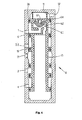
- the trailer brake valve (8) is in Fig. 2 in the valve home position and in Fig. 3 shown in the valve breakaway position.
- the red coupling head (48) is drawn in the coupled state to identify the valve's basic position.
- the pneumatic circuit diagram is in accordance with the valve home position of the piston (7), which is designed as an actuating piston for the valve, in its unactuated state and the valid for this state paths (54) are effective, so that in the trailer brake valve (8) G2) and G1) explained above [in the case that the supply pressure is applied to the port (1), the second check valve (6) explained below is operated in the forward direction].
- Fig. 3 is provided with an O-ring seal (16) actuating piston (7) with the valve spool (10) fixed and pressure-tight.
- a pressure channel (12) in the form of a blind hole In the middle of the actuating piston valve slide assembly (7, 10) is a pressure channel (12) in the form of a blind hole.
- the actuating piston (7) has a first (17) and a second (18) effective surface.
- the first active surface (17) is formed by the cross-sectional area of the actuating piston (7) and the second active surface (18) is designed as an annular surface due to the structural combination of actuating piston (7) and valve slide (10), wherein the inner ring diameter by the outer diameter of the Valve slide seal (14) is fixed.
- the first active surface (17) is designed to be larger than the second annular active surface (18).
- the second check valve (6) is installed in the effective direction shown in the actuating piston (7), wherein both active surfaces (18) and (17) are interconnected by this check valve such that the passage direction of the check valve (6) of the second (18) to the first (17) effective area extends. Since the second active surface (18) is acted upon by the pressure applied to the supply connection (1) and the first active surface (17) by the pressure applied to the container connection (3), the second check valve (6) is always then switched in the forward direction when the voltage applied to the supply connection (1) is greater than the pressure applied to the container connection (3).
- Fig. 2 In the basic position Fig. 2 is the actuating piston valve slide assembly (7, 10) by the action of the return spring (11) on the first stop (26) of the valve housing on.
- G1 and G2 are made.
- G2 represents a direct connection, ie in the pneumatic path no mechanical intermediate links are inserted [the connection G2 corresponds to the DE 28 10 850 A1 in that the pressure applied to the local control connection (7) acts first on the relay piston (6) there as a mechanical intermediate element].
- bypass channel (46) is realized as a pressure channel within the valve housing and is in the valve home position without effect, since the parking terminal (21) connected both via the direct channel (56) and via the bypass channel (46) to the same pressure chamber is, which on the in the direction of the park connection (21) opening, in the end wall of the valve spool (10) arranged first check valve (19) and the blind hole pressure channel (12) is connected to the container port (3).
- the second check valve (6) is in the reverse direction, which causes the above-mentioned compound A1).
- a pressure channel (13) is provided in the form of a bore.
- the above-described compound A2) is produced by the direct pneumatic connection from the container connection (3) via the blind-hole pressure channel (12) and the pressure channel (13) to the brake pressure connection (2).
- the park connection (21) is connected to the container connection (3) via two pneumatic connections connected in parallel.
- the first connection leads via the direct channel (56), the second check valve (19) and the blind-hole pressure channel (12 ) to the container port (3) and the second pneumatic path leads directly bypassing the check valve via the bypass channel (46), designed as a bore pressure channel (45) and the blind hole pressure channel (12) to the container port (3); when unpressurized supply connection (1) so the effect of the first check valve (19) is canceled.
- the second check valve (6) can also be carried out by the seal shown as O-ring (16) is formed as a grooved ring in a suitable mounting direction or by a check valve is provided at another location, which connects the two pressure chambers, which exert a force on the active surfaces (17) and (18).
- a suitable slide valve seal (14) as a first slide seal and to seal against the brake pressure port (2) [this seal is important in the case of the valve home position] on the valve spool (10) a slide valve seal (15) provided as a second slide seal.
- a third (43) and fourth (44) slide valve seal are provided for sealing the bore pressure channel (45).
- these slide seals serve to seal the effective in the various valve switching positions pneumatic pressure chambers for the pneumatic paths in the valve.
- the actuating piston (7) may also be integrally connected to the valve spool (10), so that the actuating piston valve spool unit (7, 10) z. B. completely as a turned part or as a plastic injection molded part can be produced.
- the slide valve seals (14, 15, 43, 44) are arranged in the valve slide (10) and the sealing surfaces on the inner wall of the valve housing
- the slide valve seals (14, 15, 43, 44) in the valve housing, above and below the bore for the brake pressure port (2) and the inlet port for the bypass passage (46) to arrange, and the sealing surfaces on the valve spool (10) form.
- the pressure prevailing in the reservoir pressure pressure now acts on both active surfaces (17) and (18) Fig. 3 one.
- the return spring (11) is dimensioned such that it overcomes the force by the surface portion by which the second active surface (18) relative to the first active surface (17) is reduced and overcompensated such that the actuating piston valve slide assembly (7, 10) is pushed by the return spring (11) to the first stop (26).
- This is the in Fig. 2 shown valve position and the brake pressure port (2) is connected to the brake specification port (4).
- the pressure chambers connected to the brake pressure port (2) ie the service brake chambers of the spring brake cylinders, are vented, so that the brake is released.
- the trailer brake valve according to the invention is designed primarily for trailer braking systems with electronic braking force control
- the device can be used in unmodified form in conventional systems, provided that the legal requirements relating to the braking time behavior are met there.
- the explained security against an automatic rolling is then effective in these systems.
- the reduced manufacturing and installation costs are also advantageous.
- the trailer brake valve according to the invention is shown in one embodiment as a slide valve, in which the slide operation depends solely on the supply port (1) pressure applied, ie in which the container connection (3) applied pressure exerts no force on the valve spool (10).
- the trailer brake valve (8) is constructed as a pressure-relieved valve, in which on the valve spool (10) of any other connection, except the supply connection (1), which acts on this force-generating effect on a below-described effective area, a compressive force is generated.
- FIG. 4 and Fig. 5 Pneumatic diagrams, as in the lower parts of Fig. 2 and Fig. 3 are shown omitted since the too Fig. 4 and Fig. 5 belonging pneumatic diagrams are basically similar to this; there is only the difference that, as explained, the valve spool (10) after Fig. 4 and Fig. 5 not actuated by the pressure difference between the supply connection (1) and the container connection (3), but switched solely by the pressure at the supply connection (1).
- valve spool (10) is formed as mentioned as a valve spool piston, ie he combines the functions of the above-described valve spool (10) and the actuating piston (7).
- the valve spool (10) is loaded with the return spring (11) and has two positions; one in Fig. 4 illustrated basic position, in which the valve slide (10) on the first stop (26) is applied, and a in Fig. 5 shown tear-off position, in which the valve spool (10) on the second stop (27) comes to rest.
- the above-explained second check valve (6) is in Fig. 4 .
- Fig. 5 realized as a grooved ring.
- a pilot valve (60) is integrated, which consists of a valve switching member (62), a force acting on the valve switching member (62) spring (61), a first valve seat (63) and a second valve seat (64).
- the pilot valve (60) has two positions, a starting position and a switching position.
- the initial position of the pilot valve (60) is in Fig. 5 In the breakaway position, no pressure is applied to the supply connection (1), and by the action of the spring (61), the valve switching element (62) abuts against the first valve seat (63), whereby the pressure space acting on the valve slide (10) is opposite to that of FIG Supply connection (1) is sealed.
- a parked trailer [demolition position Fig. 5 ] connected to the supply pressure hose (30) the pressure at the supply port (1), and according to the applied pressure and the effective diameter (65) at the first valve seat increases (63) a compressive force is exerted on the valve switching member (62).
- This effective diameter (65) determines with the properties of the spring (61) [spring length and spring constant] a pressure threshold beyond which the valve switching member (62) lifts off from the first valve seat (63).
- Fig. 6b is in the switching position of the pilot valve (60) after Fig. 6a the effective diameter (66) increases; This introduces a switching hysteresis.
- the pressure threshold z. B. expediently set to 3.5 bar.
- the explained switching hysteresis can, for. B. be designed so that the tear-off position of the trailer brake valve is taken when falling below a pressure of 2.5 bar again.
- the first valve seat (63) acts as a ventilation seat and the second valve seat (64) acts as a vent seat; during the venting of the trailer brake valve (8), ie at the transition of the valve slide (10) when the second valve seat (64) is open [64] Fig. 5 ] from the first stop (26) to the second stop (27), there is the advantage that the venting takes place directly to the atmosphere and there are no breathing spaces, as is the case with conventional trailer brake valves. Breathing rooms have the disadvantage that moisture can penetrate into the device, which may lead to icing. Compared to conventional trailer brake valves is also the advantage that the valve switching is effective immediately and not first a characteristic must be traversed.
- the pilot valve (60) is no longer integrated in the valve spool (10), but designed as a separate 3/2-way valve (70).
- the valve switching element (62) is designed as a conventional seat valve switching element, which in the tear-off position [ Fig. 8 ] at the first valve seat (63) and in the basic position [ Fig. 7 ] rests against the second valve seat (64).
- the function is similar to the embodiments according to Fig. 4 and Fig.
- Fig. 7 . 8th modified embodiment is when the check valves (6) and (19) not realized as a grooved rings in the valve spool (10), but as a separate, arranged in the housing check valves (6 ') and (19') are executed. The groove rings (6) and (19) are then replaced by corresponding O-rings.
- Fig. 7 . 8th explained Restriction that the ventilation of the reservoir pressure tank (9) takes place only after the transition of the 3/2-way valve (70) in its switching position.
- FIG. 9 The representations after Fig. 9 and Fig. 10 show the embodiment according to Fig. 7 .
- Fig. 8 in which instead of a 3/2-way valve (70) two 2/2-way valves, a first 2/2-way valve (68) as a vent valve and a second 2/2-way valve (69) are provided as a vent valve.
- the first 2/2-way valve (68) is opened, the corresponding valve switching member is lifted from the first valve seat (63), so that a ventilation through the supply connection (1) takes place;
- the second 2/2-way valve (69) is closed, the second valve seat (64) is closed, so that according to the above-described basic position function, the valve slide (10) is pushed by Duckkraft to the first stop (26).
- the second 2/2-way valve (69) is open; the opened second valve seat (64) allows venting of the valve spool (10) acting pressure chamber, so that via the return spring (11), the tear-off position on the second stop (27) is taken.
- the first 2/2-way valve (68) [first valve seat (63)] is closed, so that the pressure chamber (67), as explained above, is separated from the supply connection (1).
Abstract
Description
Die Erfindung betrifft ein Anhängerbremsventil gemäß dem Oberbegriff des Patentanspruchs 1.The invention relates to a trailer brake valve according to the preamble of
Ein derartiges Anhängerbremsventil ist aus der
Bei dem bekannten Anhängerbremsventil für eine Zweileitungs-Druckmittelbremsanlage wird ein über den Kupplungsschlauch "Bremse" eingespeistes pneumatisches Bremssignal luftmengenverstärkt über ein im Anhängerbremsventil enthaltenes Relaisventil [dort Steuerdruckkammer (6), Relaiskolben (5), Relaiskolben-Fortsatz (28), Auslaßventil (26, 28), Einlaßventil (26, 27), Bremsdruckkammer (8)] als Bremsdruck an den Bremszylinder-Anschlüssen [dort (9), (10)] für die Bremszylinder ausgegeben.In the known trailer brake valve for a two-line pressure medium brake system via the clutch hose "brake" fed pneumatic brake signal air flow amplified via a trailer brake valve relay valve [there control pressure chamber (6), relay piston (5), relay piston extension (28), exhaust valve (26, 28), intake valve (26, 27), brake pressure chamber (8)] as brake pressure at the brake cylinder ports [there (9), (10)] output for the brake cylinder.
Als weitere Funktion ist die Abrißsicherung für den Kupplungsschlauch "Vorrat" implementiert; wird der Anschluß für die Vorratsluft [dort automatischer Bremsanschluß (20)] drucklos, so wird der Notbremskolben [dort (22)] auf seiner Oberseite drucklos und der an seiner Unterseite anliegende Vorratsbehälterdruck schiebt ihn nach oben, so daß zunächst das Auslaßventil [dort (26, 28)] schließt und in der weiteren Aufwärtsbewegung das Einlaßventil [dort (26, 27)] geöffnet wird, so daß der am Vorratsbehälter-Anschluß [dort (33)] anstehende Druck auch in die Bremskammer übertragen wird und an den Bremszylinder-Anschlüssen anliegt.As a further function, the breakaway protection for the coupling hose "supply" is implemented; if the connection for the supply air [there automatic brake connection (20)] is depressurized, then the emergency brake piston [there (22)] becomes depressurized on its upper side and that on its Bottom adjoining reservoir pressure pushes it up so that first the exhaust valve [there (26, 28)] closes and in the further upward movement, the inlet valve [there (26, 27)] is opened, so that the at the reservoir terminal [there ( 33)] is also transmitted pressure in the brake chamber and rests against the brake cylinder connections.
In dem Anhängerbremsventil ist weiter die Funktion einer Voreilung des an die Bremszylinder übertragenen Bremsdruckes gegenüber dem pneumatischen Bremssignal integriert.In the trailer brake valve, the function of an overfeed of the brake pressure transmitted to the brake cylinder is further integrated with respect to the pneumatic brake signal.
Bei der Realisierung eines Anhängerbremsventiles entsprechend der bekannten Schrift muß darauf geachtet werden, daß die konstruktionsbedingte Hysterese des Relaisventiles genügend klein wird, um sie tolerieren zu können. Hierzu muß eine gewisse Mindestbaugröße für den Relaiskolben gewählt werden, um den Einfluß der Reibkräfte, z. B. den Reibkraft-Einfluß durch die Kolbendichtung, zu reduzieren. Da die Baugröße eines derartigen Ventils die Kosten zumindest stark mitbestimmt, können diese bei diesem Konstruktionsprinzip nicht so stark reduziert werden, wie man dies eigentlich wünscht.In the realization of a trailer brake valve according to the known document must be taken to ensure that the design-related hysteresis of the relay valve is sufficiently small in order to tolerate it. For this purpose, a certain minimum size must be selected for the relay piston to the influence of frictional forces, eg. B. to reduce the frictional force influence by the piston seal. Since the size of such a valve co-determines the cost at least greatly, they can not be reduced as much as you really want in this design principle.
Aus der
Aus der
Aus der
Aus dem WABCO-Datenblatt "Wabcodruck 820 001 051 3/05.95" ist ein Doppel-Löseventil 963 001 051 0 bekannt. Da ein Doppel-Löseventil nach diesem Prinzip auch in
Das Doppel-Löseventil [dort (1) unter "Schema mit ALB-Anhänger-Bremsventil"] besteht aus einem Betriebsbrems-Löseventil [in
Das Betriebsbrems-Löseventil ist eingangsseitig pneumatisch [dort (1-1)] mit dem Vorrats-Kupplungskopf [in
In seiner Fahrtstellung [gezogene Stellung des dortigen schwarzen Betätigungsknopfes] hat das Betriebsbrems-Löseventil keinen Einfluß auf den Druck in den Betriebsbremskammern der Federspeicherbremszylinder; in seiner Lösestellung [nicht gezogene Stellung des schwarzen Betätigungsknopfes] bewirkt das Betriebsbrems-Löseventil das Lösen der Betriebsbremsen.In its driving position [pulled position of the local black operating knob], the service brake release valve has no effect on the pressure in the service brake chambers of the spring brake cylinder; in its release position [not pulled position of the black actuating button], the service brake release valve causes the release of the service brakes.
Das Betriebsbrems-Löseventil dient dazu, einen entkoppelten Anhänger zu bewegen, indem die automatische Bremse [ausgelöst durch die Vorratsleitungs-Abrißsicherung im Anhängerbremsventil] außer Kraft gesetzt wird; dies geschieht dadurch, daß in der Lösestellung Behälterdruck umgelenkt und am Versorgungsanschluß in das Anhängerbremsventil eingespeist wird [in
Das Parkventil ist eingangsseitig pneumatisch [dort (1-2)] mit dem Vorratsbehälter verbunden, wobei der Anschluß über ein Rückschlagventil [in
Das Parkventil entlüftet in seiner Parkstellung -[gezogene Stellung des dortigen roten Betätigungsknopfes] die Lösekammern der Federspeicherbremszylinder, so daß die Feststellbremsen wirksam sind; in seiner Fahrstellung [nicht gezogene Stellung des roten Betätigungsknopfes] löst das Parkventil die Feststellbremsen durch Belüftung der Federspeicher-Lösekammern.The parking valve vented in its parking position - [pulled position of the local red actuator button] the release chambers of the spring brake cylinders, so that the parking brakes are effective; In its driving position [not pulled position of the red actuating button], the parking valve releases the parking brakes by ventilating the spring-loaded release chambers.
Das vorstehend erwähnte, in Richtung der Lösekammern der Federspeicherbremszylinder öffnende Rückschlagventil hält den hohen ursprünglichen Vorratsbehälter-Druck in den Lösekammern der Federspeicherbremszylinder, selbst wenn der Behälterdruck kurzzeitig einbricht. Derartige Einbrüche können bei Leckage oder intensiven ABS-Bremsungen auftreten.The above-mentioned, in the direction of the release chambers of the spring brake cylinder opening check valve holds the high original reservoir pressure in the release chambers of the spring brake cylinder, even if the tank pressure breaks down briefly. Such burglaries can occur in case of leakage or intensive ABS braking.
Diese bekanntlich gesetzlich vorgeschriebene Funktion des Rückschlagventils wirkt auch bei einem abgestellten Anhängefahrzeug, das durch Abkuppeln in die automatische Bremsfunktion geht und bei dem das Parkventil in der Fahrstellung verbleibt.This well-known law prescribed function of the check valve is also effective in a parked trailer, which by uncoupling in the automatic Brake function goes and in which the parking valve remains in the driving position.
Wenn ein derartig abgestelltes Anhängefahrzeug dann Behälterdruck verliert und die über das Rückschlagventil gesicherten Federspeicher-Lösekammern noch immer druckbeaufschlagt bleiben, so beginnen sich bei den gelösten Feststellbremsen auch die Betriebsbremsen zu lösen und das Anhängefahrzeug kann sich in Bewegung setzen, wenn es z. B. an einer Stelle mit leicht geneigter Fahrbahn abgestellt ist.If such a parked trailer vehicle then loses container pressure and the spring-loaded release chambers secured by the check valve still remain pressurized, the service brakes begin to release at the released parking brakes and the trailer can start to move if it is z. B. is parked at a location with a slightly inclined roadway.
Bei nur leichter Fahrbahnneigung kann es vorkommen, daß der Bediener es übersieht, das Parkventil durch Ziehen des roten Betätigungsknopfes in die Parkstellung zu versetzen, zu dem der Anhänger über die automatische Bremsung zunächst fest eingebremst bleibt. Das Vergessen, beim abgestellten Anhängefahrzeug das Parkventil zu betätigen, stellt also bei dem Betrieb bekannter Anhängerbremsventile mit einem Doppel-Löseventil eine Sicherheitslücke dar.If there is only a slight incline on the road, it may happen that the operator fails to move the parking valve to the parking position by pulling the red control knob, which will then cause the trailer to remain firmly braked by automatic braking. Forgetting to operate the parking valve when the trailer is parked thus represents a safety gap in the operation of known trailer brake valves with a double release valve.
Bei einem Anhänger mit elektronischer Bremsregelung wird die Regelung des Bremsdruckes in den Bremszylindern einer Fahrzeugachse von der hierfür vorgesehenen Bremsregelelektronik vorgenommen, welche auch z. B. im Falle eines ABS-Regeleingriffes mit unterschiedlichen Reibverhältnissen auf beiden Fahrzeugseiten den Bremsdruck in den Bremszylindern auf der linken Fahrzeugseite unterschiedlich zu dem Bremsdruck in den Bremszylindern auf der rechten Fahrzeugseite aussteuert. Ebenso wird der Bremsdruck von der Bremsregelelektronik z. B. abhängig von der Beladung variiert. Für eine derartige lastabhängige Bremsung wird die Beladung z. B. über eine Druckmessung in einem Luftfederbalg ermittelt und der Bremsregelelektronik mitgeteilt, welche dann den Bremsdruck in den Bremszylindern des Anhängers entsprechend modifiziert. Für die Erzeugung des Bremsdruckes ist ein Bremsdruckmodulator vorgesehen, welcher aus elektrisch ansteuerbaren Ventilen besteht, die üblicherweise in taktender Betriebsweise von der Bremsregelelektronik angesteuert werden und als Pilotventile zur Erzeugung eines Steuerdrucks in der Steuerkammer eines Relaisventiles dienen, welches den Steuerdruck luftmengenverstärkt als Bremsdruck über seinen Ausgang an einen oder mehrere Bremszylinder abgibt; hierbei können ein oder mehrere derartig aufgebaute Bremsregelkanäle implementiert sein.In a trailer with electronic brake control, the regulation of the brake pressure in the brake cylinders of a vehicle axle is made by the brake control electronics provided for this purpose, which also z. B. in the case of an ABS control intervention with different friction conditions on both sides of the vehicle, the brake pressure in the brake cylinders on the left side of the vehicle different from the brake pressure in the brake cylinders on the right side of the vehicle aussteuert. Likewise, the brake pressure from the brake control electronics z. B. varies depending on the load. For such load-dependent braking, the load z. B. determined via a pressure measurement in a bellows and notified the brake control electronics, which then modifies the brake pressure in the brake cylinders of the trailer accordingly. For the generation of the brake pressure, a brake pressure modulator is provided, which consists of electrically controllable valves, which are usually controlled in clocking mode of operation of the brake control electronics and serve as pilot valves for generating a control pressure in the control chamber of a relay valve, which air mass amplifies the control pressure as a brake pressure on its output to one or more brake cylinders; In this case, one or more brake control channels constructed in this way can be implemented.
Ein Anhängerbremsventil für den Einsatz in einem Anhänger mit elektronischer Bremsregelung braucht daher weder über die Funktion der Luftmengenverstärkung noch über Sonderfunktionen wie z. B. die erwähnte Funktion einer Voreilung oder diejenige einer lastabhängigen Modifizierung des Bremsdruckes zu verfügen. Für ein solches Anhängerbremsventil ist es völlig ausreichend, wenn die Grundfunktionen, nämlich die Bereitstellung des vom Zugfahrzeug übertragenen Bremsvorgabedruckes, die Abrißsicherung sowie die Möglichkeit des Anschlusses eines vorstehend erläuterten Doppel-Löseventiles realisiert sind.A trailer brake valve for use in a trailer with electronic brake control therefore needs neither the function of the air quantity gain nor special functions such. As the aforementioned function of an overfeed or that of a load-dependent modification of the brake pressure to dispose. For such a trailer brake valve, it is quite sufficient if the basic functions, namely the provision of the transmitted braking force from the towing vehicle, the anti-tamper and the possibility of connection of a double-release valve explained above are realized.
Der Erfindung liegt deshalb die Aufgabe zugrunde, für ein Anhängerbremsventil nach der erstgenannten bekannten Schrift eine Ventilkonstruktion anzugeben, die entsprechend den reduzierten Anforderungen des Einsatzes des Anhängerbremsventiles in einem Anhänger mit elektronischer Bremsregelung zur Verringerung der Herstellkosten vereinfacht ist, und bei der bei geparktem Anhängefahrzeug eine erhöhte Sicherheit gegen ein unbeabsichtigtes Anrollen gegeben ist.The invention is therefore the object of a trailer brake valve after the former known To provide a valve design, which is simplified according to the reduced requirements of the use of the trailer brake valve in a trailer with electronic brake control to reduce manufacturing costs, and in which parked trailer vehicle increased security against accidental startup is given.
Diese Aufgabe wird durch die im Patentanspruch 1 angegebene Erfindung gelöst. Weiterbildungen und vorteilhafte Ausführungsbeispiele der Erfindung sind in den Unteransprüchen angegeben.This object is achieved by the invention defined in
Die Erfindung hat den Vorteil, daß für die erhöhte Sicherheit gegen ein unbeabsichtigtes Anrollen auf Seiten des Anhängers keinerlei zusätzliche Komponenten oder Verrohrungen erforderlich sind.The invention has the advantage that no additional components or piping are required for increased safety against unintentional rolling on the trailer side.
Zusätzlich hat die Erfindung den Vorteil, daß die Fehleranfälligkeit durch den im Vergleich zum Stand der Technik wesentlich vereinfachten Aufbau erheblich reduziert ist.In addition, the invention has the advantage that the susceptibility to errors is significantly reduced by the significantly simplified compared to the prior art construction.
Relaisventile sind durch die Entlüftung der Relaisventil-Druckkammer nicht frei von Luftverbrauch. Mit dem Entfallen einer luftmengenverstärkenden.nach dem Relaisventil-Prinzip arbeitenden Ventileinrichtung nach der Erfindung entsteht der Vorteil, daß kein Luftverbrauch mehr erfolgt und die mit einem Luftverbrauch verbundene Geräuschentwicklung ebenfalls nicht stattfindet.Relay valves are not free from air consumption due to the venting of the relay valve pressure chamber. With the elimination of a luftmengenverstärkenden.nach the relay valve principle working valve device according to the invention has the advantage that no more air consumption takes place and associated with an air consumption noise also does not take place.
Durch das Entfallen eines Relaisventiles entfällt die Relaiskolben-Hysterese, was erstens zu dem Vorteil einer verbesserten Genauigkeit und zweitens zu dem Vorteil führt, daß kein verzögertes Ansprechen des ausgesteuerten Druckes gegenüber dem eingesteuerten Druck mehr vorhanden ist. Der Ansprechdruck mußte also beim St. d. T. zunächst von dem pneumatischen Bremssignal überschritten werden, damit das pneumatische Bremssignal luftmengenverstärkt durchgesteuert werden kann.By eliminating a relay valve eliminates the relay piston hysteresis, which leads firstly to the advantage of improved accuracy and secondly to the advantage that no delayed response of the controlled pressure against the applied pressure is more present. The set pressure had therefore at St. d. T. initially exceeded by the pneumatic brake signal, so that the pneumatic brake signal can be controlled by air volume.
Mit dem Wegfall einer Voreilung ist der Vorteil einer verbesserten Genauigkeit verbunden; außerdem entfällt durch den Wegfall der Voreilungsfunktion das fehlerträchtige und möglicherweise sogar mißbräuchliche Einstellen der Voreilung.With the elimination of a lead, the advantage of improved accuracy is associated; In addition, eliminating the override function eliminates the error-prone and possibly even abusive setting of the overfeed.
Eine Weiterbildung der Erfindung hat den Vorteil, daß durch den Wegfall des Relaisventiles mit seiner Zeitverzögerung "Ausgang-Eingang" von i. Allg. mehr als 30 ms ein Zeitvorteil für das elektrische Signal des Drucksensors verbunden ist, weil dieser Drucksensor den vom Anhängerbremsventil ausgegebenen Bremsdruck mißt.A development of the invention has the advantage that by eliminating the relay valve with its time delay "output input" of i. Gen. more than 30 ms, a time advantage for the electrical signal of the pressure sensor is connected, because this pressure sensor measures the output from the trailer brake valve brake pressure.
Stark verallgemeinert ist bei der Erfindung der pneumatische Pfad optimiert, weil dieser im Gegensatz zu der im Normalfall wirksamen elektrischen Bremssignal-Übertragung nur für die Notbremsung vorgesehen ist, bei der auf eine lastabhängige Bremsdruckbeeinflussung verzichtet werden kann. Mit dem optimierten pneumatischen Pfad entsteht der Vorteil, daß zum einen luftverbrauchende Einrichtungen entfallen und zum anderen Zeitverzögerungen durch derartige Einrichtungen auch nicht mehr auftreten.Broadly generalized in the invention, the pneumatic path is optimized, because this is provided in contrast to the normally effective electrical brake signal transmission only for emergency braking, in which can be dispensed with a load-dependent brake pressure influencing. With the optimized pneumatic path has the advantage that on the one hand accounts air-consuming facilities and on the other time delays caused by such facilities no longer occur.
Eine andere Weiterbildung der Erfindung hat den Vorteil, daß die Umschaltung des Anhängerbremsventils in die Abrißstellung nur vom am Versorgungsanschluß des Ventils [dieser ist pneumatisch mit dem roten Kupplungskopf verbunden] anliegenden Druck abhängt. Der Übergang von einer in die andere Schaltstellung erfolgt zudem schlagartig, so daß das Schalten auch reibungsunabhängig erfolgt und schleichende Übergänge vermieden werden. Somit erfolgt beim Versorgungsleitungs-Abriß die Zwangsbremsung "sofort", und es muß gegenüber konventionellen Lösungen zunächst keine Kennlinie durchfahren werden. Das Ventil ist als druckausgeglichenes Ventil mit positiver Überdeckung ausgeführt; gegenüber konventionellen Lösungen hat diese Weiterbildung auch den Vorteil, daß atmende Räume und die damit verbundenen Vereisungsgefahren vermieden werden.Another development of the invention has the advantage that the switching of the trailer brake valve in the tear-off position depends only on the supply port of the valve [this is pneumatically connected to the red coupling head] applied pressure. The transition from one to the other switching position also takes place abruptly, so that the switching is also independent of friction and creeping transitions are avoided. Thus, in the supply line demolition, the emergency braking "immediately", and it must be compared with conventional solutions initially no characteristic traversed. The valve is designed as a pressure compensated positive overlap valve; Compared to conventional solutions, this development also has the advantage that breathing spaces and the associated risk of icing are avoided.
Von der letztgenannten Weiterbildung gibt es verschiedene Ausführungsformen, die entsprechend dem jeweils bevorzugten Lösungsweg bestimmte Vorteile bieten.Of the last-mentioned further development, there are various embodiments which offer certain advantages in accordance with the respectively preferred approach.
Die Erfindung wird im folgenden anhand eines Ausführungsbeispiels, das in den Zeichnungen dargestellt ist, näher erläutert.The invention is explained in more detail below with reference to an embodiment which is illustrated in the drawings.
Es zeigt:
- Fig. 1
- Das Anhängerbremsventil in dem Blockschaltbild einer Anhänger-EBS-Bremsanlage;
- Fig. 2
- das als Schieberventil ausgeführte Anhängerbremsventil bei gekoppeltem Vorrats-Druckschlauch;
- Fig. 3
- das als Schieberventil ausgeführte Anhängerbremsventil bei entkoppeltem Vorrats-Druckschlauch.
- Fig. 4
- ein als Schieberventil mit einem integrierten Vorsteuerventil ausgebildetes Anhängerbremsventil, bei dem die Ventilbetätigung unabhängig von dem Behälterdruck erfolgt, in der Grundstellung;
- Fig. 5
- das Anhängerbremsventil nach
Fig. 4 in der Abrißstellung; - Fig. 6
- eine Detaildarstellung des Vorsteuerventils in der Grund- (
Fig. 6a ) und Abrißstellung (Fig. 6b ); - Fig. 7
- ein Anhängerbremsventil nach dem Prinzip von
Fig. 4 , bei dem das Vorsteuerventil als separates 3/2-Wegeventil ausgebildet ist, in der Grundstellung; - Fig. 8
- das Anhängerbremsventil nach
Fig. 7 in der Abrißstellung; - Fig. 9
- ein Anhängerbremsventil nach dem Prinzip von
Fig. 6 , bei dem das Vorsteuerventil als eineKombination von zwei 2/2-Wegeventilen ausgebildet ist, in der Grundstellung; - Fig. 10
- das Anhängerbremsventil nach
Fig. 9 in der Abrißstellung.
- Fig. 1
- The trailer brake valve in the block diagram of a trailer EBS brake system;
- Fig. 2
- the trailer brake valve designed as a slide valve with coupled supply-pressure hose;
- Fig. 3
- the trailer brake valve designed as a slide valve with decoupled supply pressure hose.
- Fig. 4
- a trailer brake valve designed as a slide valve with an integrated pilot valve, in which the valve actuation takes place independently of the container pressure, in the basic position;
- Fig. 5
- the trailer brake valve
Fig. 4 in the demolition position; - Fig. 6
- a detail of the pilot valve in the basic (
Fig. 6a ) and demolition position (Fig. 6b ); - Fig. 7
- a trailer brake valve according to the principle of
Fig. 4 in which the pilot valve is designed as a separate 3/2-way valve, in the basic position; - Fig. 8
- the trailer brake valve
Fig. 7 in the demolition position; - Fig. 9
- a trailer brake valve according to the principle of
Fig. 6 in which the pilot valve as a combination of two 2/2-way valves is formed, in the basic position; - Fig. 10
- the trailer brake valve
Fig. 9 in the demolition position.
Anhand von
Dem Blockschaltbild nach
Der Anhänger mit dem erfindungsgemäßen Anhängerbremsventil ist mit dem Zugfahrzeug pneumatisch über zwei Druckschläuche, über erstens einen Vorrats-Druckschlauch (30) zur Übertragung des Versorgungsdruckes [am Zugfahrzeug befestigter roter Druckschlauch, der über den "roten Kupplungskopf" (48) des Anhängers angekuppelt ist] und über zweitens einen Brems-Druckschlauch (31) zur Übertragung des Bremsdruckes [am Zugfahrzeug befestigte gelbe Leitung, die über den "gelben Kupplungskopf" (49) des Anhängers angekuppelt ist] verbunden. Auf der Seite des Zugfahrzeuges ist sowohl der rote Druckschlauch als auch der gelbe Druckschlauch pneumatisch an ein Anhängersteuerventil [AST-Ventil] angeschlossen.The trailer with the trailer brake valve according to the invention with the towing vehicle pneumatically via two pressure hoses, via first a supply pressure hose (30) for transmitting the supply pressure [attached to the towing vehicle red pressure hose, which is coupled via the "red coupling head" (48) of the trailer] and second, a brake pressure hose (31) for transmitting the brake pressure [tractor-mounted yellow wire coupled via the trailer's yellow coupling head (49)]. On the side of the towing vehicle is both the Red pressure hose and the yellow pressure hose are pneumatically connected to a trailer control valve [AST valve].
Anhängerseitig ist der Vorrats-Druckschlauch (30) pneumatisch über das vorstehend erläuterte Betriebsbrems-Löseventil (33) mit dem Versorgungsanschluß (1), und der Brems-Druckschlauch (31) über eine Pneumatikleitung mit dem Bremsvorgabeanschluß (4) des Anhängerbremsventiles (8) verbunden. Das Anhängerbremsventil (8) verfügt weiter über einen Behälteranschluß (3), an dem der Vorrats-Druckbehälter (9) für den Anhänger angeschlossen ist, und über einen Bremsdruckanschluß (2), an dem der pneumatische Bremsdruck an den pneumatischen Eingang (28) des pneumatischen Bremsdruckmodulators (29) ausgegeben wird; dieser Bremsdruck stellt für den Anhänger mit seiner elektronischen Bremsdruckregelung den Redundanzdruck dar.On the trailer side, the supply pressure hose (30) is pneumatically connected via the above-described service brake release valve (33) to the supply port (1), and the brake pressure hose (31) via a pneumatic line to the brake specification port (4) of the trailer brake valve (8) , The trailer brake valve (8) further has a container port (3) to which the reservoir pressure vessel (9) is connected for the trailer, and a brake pressure port (2), at which the pneumatic brake pressure to the pneumatic input (28) of the pneumatic Bremsdruckmodulators (29) is output; This brake pressure represents the redundant pressure for the trailer with its electronic brake pressure control.
Bei dem Anhänger mit der elektronischen Bremsdruckregelung wird in allen denkbaren Fällen, in denen eine Bremsung stattfinden soll, am Bremsdruckanschluß (2) ein entsprechender Redundanzdruck ausgesteuert. Bei normalen Bremsvorgängen gilt dies, da der Anhänger natürlich mit jeder Art von entsprechend zugelassenen Zugfahrzeugen zu koppeln sein muß, sowohl für den Fall, daß das Zugfahrzeug über eine elektronische Bremsregelung verfügt, als auch für den Fall, daß das Zugfahrzeug mit einer konventionellen pneumatischen Bremsanlage ausgerüstet ist. Bei einem Zugfahrzeug mit elektronischer Bremsregelung wird ein Bremsvorgang durch Betätigung des zum Regelsystem gehörenden Bremswertgebers eingeleitet, während dies bei einem konventionellen Zugfahrzeug durch Betätigung des entsprechenden Motorwagen-Bremsventils erfolgt.In the trailer with the electronic brake pressure control in all conceivable cases in which braking is to take place, at the brake pressure port (2) a corresponding redundant pressure is controlled. In normal braking operations this is because the trailer must of course be coupled with any type of suitably approved towing vehicles, both in the event that the towing vehicle has electronic brake control, and in the event that the towing vehicle is equipped with a conventional pneumatic braking system equipped. In a towing vehicle with electronic brake control is a braking operation by operating the brake system belonging to the control system initiated, while this is done in a conventional towing vehicle by actuation of the corresponding motor vehicle brake valve.
Beim Motorwagen [dieser stellt das Zugfahrzeug dar] mit elektronischer Bremsregelung, bei dem im Normalfall natürlich der von der elektronischen Anhänger-Bremsregelung eingestellte Bremsdruck durch das vom Motorwagen über die elektrische Schnittstelle (32) [ISO 7638/CAN] zum Anhänger übertragene elektrische BremsanforderungsSignal bestimmt ist, wird der Redundanzdruck im Anhänger im Fehlerfall zum Bremsen herangezogen, wenn nämlich die Motorwagen-Elektronik ausgefallen ist. Bei Verwendung eines konventionell gebremsten Motorwagens dient der "Redundanzdruck" im Anhänger zur Bremsung des Anhängers überhaupt, da ein derartiger Motorwagen die elektronische Bremsdruckregelung im Anhänger nicht ansprechen kann. Die Umsetzung des pneumatischen Bremssignals in ein elektronisches Signal erfolgt durch den Drucksensor (47) im Anhänger.In the case of the towing vehicle [this is the towing vehicle] with electronic brake control, in which, of course, the brake pressure set by the electronic trailer brake control is determined by the electric brake request signal transmitted from the towing vehicle via the electrical interface (32) [ISO 7638 / CAN] to the trailer is, the redundancy pressure in the trailer in case of failure is used for braking, namely, when the motor vehicle electronics has failed. When using a conventionally braked motor car, the "redundancy pressure" in the trailer is used to brake the trailer at all, since such a motor vehicle, the electronic brake pressure control in the trailer can not respond. The implementation of the pneumatic brake signal in an electronic signal is carried out by the pressure sensor (47) in the trailer.
Außer diesen normalen Bremsvorgängen wird auch vom Anhängerbremsventil (8) ein Vollbremsdruck zum Modulator (29) durchgesteuert, der eine rein pneumatische Bremsung ohne Zutun der Elektronik erlaubt. Bei Abriß einer der beiden Pneumatikleitungen zwischen Zugfahrzeug und Anhänger oder bei nicht gekuppeltem rotem Kupplungskopf wird in bekannter Weise durch das Zusammenwirken zwischen Anhängersteuerventil im Zugfahrzeug und Anhängerbremsventil eine Zwangsbremsung mittels des Behälterdruckes ausgelöst, indem, wie unten erläutert, in diesem Fall im Anhängerbremsventil (8) der Behälteranschluß (3) pneumatisch mit dem Bremsdruckanschluß (2) verbunden wird.In addition to these normal braking operations, the trailer brake valve (8) also controls a full brake pressure to the modulator (29), which allows purely pneumatic braking without the intervention of the electronics. In demolition of one of the two pneumatic lines between towing vehicle and trailer or uncoupled red coupling head emergency braking by means of the tank pressure is triggered in a known manner by the interaction between the trailer control valve in the towing vehicle and trailer brake valve by, as explained below, in this case in the trailer brake valve (8). the tank connection (3) is pneumatically connected to the brake pressure port (2).
Zusammenfassend kann gesagt werden, daß in allen Fällen, in denen eine Bremsung des Anhängers erforderlich ist, sei dies eine normale Bremsung oder eine Zwangsbremsung, vom Anhängerbremsventil (8) am Bremsdruckanschluß (2) ein Druck, entweder der Redundanzdruck oder der Behälterdruck, ausgegeben wird, welcher dem pneumatischen Bremsdruckmodulator (29) zugeführt wird.In summary, in all cases where trailer braking is required, whether normal braking or emergency braking, the trailer brake valve (8) at the brake pressure port (2) outputs a pressure, either the redundant pressure or the reservoir pressure which is supplied to the pneumatic brake pressure modulator (29).
Der Bremsdruckmodulator (29) verfügt weiter über einen Druckversorgungsanschluß (35), der durch eine Pneumatikleitung mit dem Vorrats-Druckbehälter (9) verbunden ist. Der Bremsdruckmodulator (29) wird über elektrische Verbindungen durch die Elektronikeinheit (42) gesteuert.The brake pressure modulator (29) further has a pressure supply port (35) which is connected by a pneumatic line to the supply pressure vessel (9). The brake pressure modulator (29) is controlled by electrical connections through the electronics unit (42).
Der pneumatische Bremsdruckmodulator (29) ist z. B. als zwei-kanaliges Druckregelmodul nach der
Bei einer Realisierung nach der S1 ist für beide Kanäle ein gemeinsames 3/2-Magnetventil [dort (12)] als Umschaltventil für weitere kanalspezifische Belüftungs- und Entlüftungs-Magnetventile [dort (9') und (7) bzw.(9) und (8)] vorgesehen, welche für den Fall der EBS-Bremsdruckregelung mit einer taktenden Betriebsweise Pilot-Bremsdrücke je Kanal aussteuern, die wiederum an Steuereingänge [dort (5) bzw. (6)] von pro Kanal vorgesehenen Relaisventilen [dort (3) bzw. (4)] angelegt sind. Die Relaisventil-Arbeitsanschlüsse [dort (20) und (22) bzw. (21) und (23)] sind, wie in
Der pneumatische Eingang (28) ist mit dem Steuerdruck-Anschluß [dort (13)] und der Druckversorgungsanschluß (35) ist mit dem Vorratsdruck-Anschluß [dort (17)] des Druckregelmoduls nach der S1 verbunden. In seiner federbetätigten Grundstellung, d. h. in seinem stromlosen Zustand, wird von dem 3/2-Magnetventil [dort (12)] der S1 der am pneumatischen Eingang (28) nach
Im strombeaufschlagten Zustand, d. h. gesteuert durch die Elektronikeinheit (42) nach
Auf diese Weise wird im Rahmen der EBS-Bremsdruckregelung auch eine ladungsabhängige Bremskraftverteilung zwischen den Fahrzeugachsen vorgenommen. Hierzu ist - es wird von einem luftgefederten Auflieger mit Luftfederbälgen auf der linken und rechten Fahrzeugseite ausgegangen - der Luftfederbalg auf der rechten Seite üblicherweise mit einem Drucksensor versehen, dessen Druckmeßwert der Elektronikeinheit (42) zur Verfügung steht. Die Elektronikeinheit (42) modifiziert die ausgesteuerten Bremsdrücke beladungsabhängig unter Verwendung dieses die Beladung des Fahrzeugs repräsentierenden Druckmeßwertes.In this way, as part of the EBS brake pressure control, a charge-dependent brake force distribution between the vehicle axles is made. For this purpose - it is assumed that an air-suspended semi-trailer with air bellows on the left and right side of the vehicle - the bellows on the right side usually provided with a pressure sensor, the pressure measurement of the electronic unit (42) is available. The electronic unit (42) modifies the controlled brake pressures in a load-dependent manner using this pressure measurement value representing the load of the vehicle.
Die Elektronikeinheit (42) verwendet für die EBS-Bremsdruckregelung auch den Druckmeßwert des Drucksensors (47), der den am Bremsdruckanschluß (2) ausgegebenen Bremsdruck des Anhängerbremsventiles (8) darstellt. Dieser Druckmeßwert ist für den Fall eines konventionellen Zugfahrzeuges vorgesehen, bei dem die Elektronikeinheit (42) den elektrischen Druckmeßwert als elektrisches Bremsanforderungssignal für die EBS-Bremsdruckregelung benutzt.The electronic unit (42) also uses the pressure measurement value of the pressure sensor (47) for the EBS brake pressure control, which represents the brake pressure of the trailer brake valve (8) output at the brake pressure connection (2). This pressure reading is provided in the case of a conventional towing vehicle in which the electronics unit (42) uses the electrical pressure reading as the EBS brake pressure control electrical brake request signal.
Der Vollständigkeit halber sei ergänzt, daß die ABS-Bremsregelung auch durch die Einrichtungen der EBS-Bremsdruckregelung durchgeführt wird; hierzu sind an den linken und rechten Rädern, die durch die Federspeicherbremszylinder [(38) und (39) bzw. (40) und (41)] gebremst werden, entsprechende ABS-Sensoren zur Erfassung der jeweiligen Radgeschwindigkeiten vorgesehen.For completeness, it should be added that the ABS brake control is also performed by the EBS brake pressure control devices; this is on the left and right wheels, which are braked by the spring brake cylinders [(38) and (39) and (40) and (41)], provided corresponding ABS sensors for detecting the respective wheel speeds.
Faßt man alle Funktionen der EBS-Bremsdruckregelung zusammen, so müssen für das Anhängerbremsventil (8) nur noch pneumatische Funktionen realisiert sein, die durch zwei Schaltzustände definiert sind: Zum einen ist dies die Ventil-Grundstellung, die vorliegt, wenn der Versorgungsanschluß mit Druck beaufschlagt ist, und zum anderen ist dies die Ventil-Abrißstellung, welche bei drucklosem Versorgungsanschluß (1) gegeben ist.If one summarizes all functions of the EBS brake pressure control, then only pneumatic functions must be implemented for the trailer brake valve (8), which are defined by two switching states: First, this is the valve home position, which is present when the supply port pressurized On the other hand, this is the valve-breakaway position, which is given at unpressurized supply connection (1).
In der Ventil-Grundstellung sind durch das Anhängersteuerventil (8) folgende Verbindungen hergestellt:
- G1) - Der Versorgungsanschluß (1) ist pneumatisch über das zweite Rückschlagventil (6) mit dem Behälteranschluß (3) verbunden;
- G2) - der Bremsdruckanschluß (2) ist pneumatisch mit dem Bremsvorgabeanschluß (4) verbunden.
- G1) - The supply connection (1) is pneumatically connected via the second check valve (6) to the container connection (3);
- G2) - the brake pressure connection (2) is pneumatically connected to the brake specification port (4).
In seiner Ventil-Abrißstellung sind durch das Anhängerbremsventil (8) folgende Verbindungen hergestellt:
- A1) - Der Versorgungsanschluß (1) ist durch das zweite Rückschlagventil (6) pneumatisch abgeschlosssen;
- A2) - der Bremsdruckanschluß (2) ist pneumatisch mit dem Behälteranschluß (3) verbunden.
- A1) - The supply connection (1) is pneumatically closed by the second check valve (6);
- A2) - the brake pressure connection (2) is pneumatic connected to the container port (3).
Neben diesen Funktionen für die EBS-Bremsdruckregelung enthält das Anhängerbremsventil Anschlußmöglichkeiten für die Funktionsbaugruppen des Doppel-Löseventils, d. h. den Anschluß des Betriebsbrems-Löseventils (33) und des Parkventils (20).In addition to these functions for the EBS brake pressure control, the trailer brake valve includes connection options for the function modules of the double release valve, d. H. the connection of the service brake release valve (33) and the parking valve (20).
In
Für den Anschluß des Betriebsbrems-Löseventils (33) ist der vorstehend bereits erwähnte Löseanschluß (5) vorgesehen, welcher durch eine im Anhängersteuerventil (8) bestehende direkte pneumatische Verbindung mit dem Behälteranschluß (3) verbunden ist.For the connection of the service brake release valve (33) of the above-mentioned release connection (5) is provided, which is connected by a trailer in the control valve (8) existing direct pneumatic connection with the container port (3).
Wenn nun das in
Der Anschluß des Parkventils (20) an das Anhängerbremsventil (8) erfolgt nicht wie bei dem St. d. T. über den Vorratsbehälter, sondern über einen separaten Parkanschluß (21); innerhalb des Anhängerbremsventils (8) ist der Parkanschluß (21) über das bereits vorstehend erwähnte, in Richtung des Parkanschlusses (21) öffnende, erste Rückschlagventil (19) mit dem Behälteranschluß (3) verbunden [dieses Rückschlagventil ist, wie vorstehend erläutert, beim St.d.T. im Parkventil des Doppel-Löseventils untergebracht].The connection of the parking valve (20) to the trailer brake valve (8) does not take place as in the St. d. T. via the reservoir, but via a separate parking terminal (21); within the trailer brake valve (8), the parking connection (21) is opened via the already mentioned above, in the direction of the parking connection (21), first check valve (19) connected to the container port (3) [this check valve is, as explained above, housed in St.DT in the parking valve of the double release valve].
Bei dem in
In der Parkstellung des Parkventils (20) [Betätigungsknopf "gezogen"] werden die Lösekammern der Federspeicherbremszylinder über den in dieser Ventilstellung wirksamen Druckkanal (22) entlüftet, was dazu führt, daß die Feststellbremsen der Federspeicherbremszylinder wieder wirksam werden.In the parking position of the parking valve (20) [operating knob "pulled"] the release chambers of the spring brake cylinder are vented via the effective in this valve position pressure channel (22), which causes the parking brakes of the spring brake cylinders are effective again.
Erfindungsgemäß ist im Anhängerbremsventil (8) am Parkanschluß (21) parallel zum ersten Rückschlagventil (19) ein Bypasskanal (46) vorgesehen, welcher in der Ventil-Grundstellung des Anhängerbremsventiles (8) ohne Bedeutung ist, da er über die in diesem Schaltzustand wirksamen Wege (54) abgeschlossen ist.According to the invention, a bypass channel (46) is provided in the trailer brake valve (8) parallel to the first check valve (19) in the trailer brake valve (21), which is irrelevant in the valve basic position of the trailer brake valve (8) since it has effective paths in this switching state (54) is completed.
In der Ventil-Abrißstellung werden jedoch die Wege der Ventil-Abrißstellung (55) wirksam und in dieser Stellung liegt der Behälterdruck über den Bypasskanal (46) direkt am Parkanschluß (21) an; in dieser Ventilstellung liegt der Behälterdruck außerdem auch am Bremsdruckanschluß (2) an.In the valve breakaway position, however, the paths of the valve breakaway position (55) become effective and in this position the tank pressure is applied via the bypass duct (46) directly to the parking terminal (21); In this valve position, the tank pressure is also at the brake pressure port (2).
In der Ventil-Abrißstellung - das Parkventil (20) befindet sich in seiner in
Im Rahmen eines leckagebedingten Druckabbaus im Vorratsbehälter (9) nimmt die Wirkung der Betriebsbremsen ab; gleichzeitig nimmt aber auch das Lösen der Feststellbremse ab, so daß die Wirkung der Feststellbremse zunimmt. Im Verlauf des Druckabbaus überwiegt bei einem durch die Geräteauslegung [Federkraft/Druckfläche] vorgegebenen Druckniveau je nach Auslegung die Wirkung der Betriebs- oder die Wirkung der Feststellbremsen: Damit ist bei jedem Druckniveau eine Restbremswirkung für den Anhänger vorhanden, die entweder von den Betriebs- oder von den Feststellbremsen kommt.As part of a leakage-induced pressure reduction in the reservoir (9) decreases the effect of service brakes; but at the same time also decreases the release of the parking brake, so that the effect of the parking brake increases. Depending on the design, the effect of the operating or the effect of the parking brakes prevails at a given by the device design [spring force / pressure surface] pressure level: Thus, at any pressure level a residual braking effect for the trailer is present, either from the operating or comes from the parking brakes.
Unter Verwendung der erfindungsgemäßen Einrichtung wird ein Anhänger, der an einer Fahrbahn mit nur mäßiger Fahrbahnneigung aufgestellt ist, nicht selbständig anrollen; die Sicherheit gegenüber einem automatischen Wegrollen des Anhängers ist damit entscheidend verbessert.Using the device according to the invention, a trailer that is placed on a roadway with only moderate road gradient, not self-roll on; the security against automatic rolling of the trailer is thus significantly improved.
Bei einem abgestellten Anhänger ist ein sicherer Zustand erreicht, wenn das Parkventil durch Ziehen des Betätigungsknopfes in die Parkstellung versetzt worden ist und damit die Feststellbremsen dauerhaft wirksam sind. Leider wird manchmal vergessen, den Betätigungsknopf zu ziehen, da das abgestellte Fahrzeug durch die automatische Zwangsbremsung ja zunächst als sicher abgebremst erscheint. Die Erfindung erhöht die Sicherheit vor allem dadurch, daß auch bei der Fehlbedienung, das Parkventil nicht in den Parkzustand zu versetzen, der Anhänger stets ausreichend abgebremst bleibt und damit praktisch nicht wegrollen kann.In a parked trailer a secure state is achieved when the parking valve has been moved by pulling the knob in the park position and thus the parking brakes are permanently effective. Unfortunately, it is sometimes forgotten to pull the control button, because the parked vehicle by the automatic forced braking so first seems to be braked safely. The invention increases safety above all by the fact that even in the incorrect operation, not to put the parking valve in the park state, the trailer always brakes sufficiently and thus practically can not roll.
Für verringerte Anforderungen oder andersartige Anlagen [z. B. ohne Federspeicherbremszylinder] kann gegebenenfalls auch auf die Verwendung der erläuterten Löse- bzw. Parkventilfunktion verzichtet werden. Bei einer derartigen Ausführung sind der rote Kupplungskopf (48) direkt an den Versorgungsanschluß (1) und die Löseleitung (53) direkt an den Parkanschluß (21) angeschlossen. Durch das Fehlen des Parkventils kann das abgestellte Fahrzeug dann nicht mehr über die Feststellbremsen gesichert werden, und das Lösen der automatischen Zwangsbremsung erfolgt mit dem erneuten Anschluß des Versorgungsleitungs-Druckschlauches an das Zugfahrzeug. Es ist jedoch wichtig, daß selbst in einer derart vereinfachten Anlage die erläuterten Maßnahmen gegen ein automatisches Wegrollen wirksam sind. Ergänzt sei, daß es natürlich auch die Möglichkeit gibt, ein Betriebsbrems-Löseventil oder ein Parkventil als einzelnes Ventil einzusetzen.For reduced requirements or other types of equipment [eg. B. without spring brake cylinder] may optionally be dispensed with the use of the illustrated release or parking valve function. In such an embodiment, the red coupling head (48) directly to the supply terminal (1) and the release line (53) are connected directly to the parking terminal (21). Due to the absence of the parking valve the parked vehicle can then no longer be secured by the parking brakes, and the release of the automatic emergency braking takes place with the reconnection of the supply line pressure hose to the towing vehicle. However, it is important that even in such a simplified system, the described measures against automatic rolling are effective. It should be added that it is of course also possible to use a service brake release valve or a parking valve as a single valve.
Es besteht auch die Möglichkeit, das erfindungsgemäße Anhängerbremsventil mit einem Betriebsbrems-Löseventil und/oder einem Parkventil in einem Gehäuse baulich zu vereinigen.It is also possible to structurally combine the trailer brake valve according to the invention with a service brake release valve and / or a parking valve in a housing.
Es sei noch ergänzt, daß das Bremsüberlast-Wechselventil (52) dazu dient, die Bremsen davor zu schützen, daß eine zu große Zuspannkraft auf sie einwirkt, wenn die Feststell- und die Betriebsbremse gleichzeitig wirksam werden.It should be added that the brake overload shuttle valve (52) serves to protect the brakes against the fact that an excessive clamping force acts on them when the parking brake and the service brake are effective at the same time.
Sollte die Feststellbremse wirksam sein, indem in der Löseleitung (53) Druck anliegt, und gleichzeitig an den Zylinder-Betriebsbremsleitungen (37) ein Betriebsbremsdruck anliegen, so reduziert dieser Betriebsbremsdruck über das Überlast-Wechselventil (52) den Lösedruck in den Federspeicher-Löseleitungen (50) derart, daß die von den Feststellbremsen ausgeübte Bremskraft um die Kraft der Betriebsbremsen reduziert wird.Should the parking brake be effective by applying pressure in the release line (53) and at the same time bear a service brake pressure at the cylinder service brake lines (37), this service brake pressure via the overload shuttle valve (52) reduces the release pressure in the spring-loaded release lines (FIG. 50) such that the braking force exerted by the parking brakes is reduced by the force of the service brakes.
In
Im jeweils unteren Bereich der Darstellungen von
Das Anhängerbremsventil (8) ist in
Bei
Bei
Bei der konstruktiven Ausgestaltung des Anhängerbremsventils (8) als Schieberventil entsprechend den jeweils oberen Bereichen von
In der Mitte der Betätigungskolben-Ventilschieber-Anordnung (7, 10) befindet sich ein Druckkanal (12) in Form eines Sackloches.In the middle of the actuating piston valve slide assembly (7, 10) is a pressure channel (12) in the form of a blind hole.
Der Betätigungskolben (7) weist eine erste (17) und eine zweite (18) Wirkfläche auf. Die erste Wirkfläche (17) ist durch die Querschnittsfläche des Betätigungskolbens (7) gebildet und die zweite Wirkfläche (18) ist aufgrund der baulichen Vereinigung von Betätigungskolben (7) und Ventilschieber (10) als Ringfläche ausgestaltet, wobei der innere Ringdurchmesser durch den Außendurchmesser der Ventilschieberdichtung (14) festgelegt ist.The actuating piston (7) has a first (17) and a second (18) effective surface. The first active surface (17) is formed by the cross-sectional area of the actuating piston (7) and the second active surface (18) is designed as an annular surface due to the structural combination of actuating piston (7) and valve slide (10), wherein the inner ring diameter by the outer diameter of the Valve slide seal (14) is fixed.
Die erste Wirkfläche (17) ist größer ausgebildet als die zweite Ring-Wirkfläche (18).The first active surface (17) is designed to be larger than the second annular active surface (18).
Das zweite Rückschlagventil (6) ist in der gezeigten Wirkrichtung im Betätigungskolben (7) eingebaut, wobei beide Wirkflächen (18) und (17) durch dieses Rückschlagventil derart miteinander verbunden sind, daß die Durchlaßrichtung des Rückschlagventils (6) von der zweiten (18) zur ersten (17) Wirkfläche verläuft. Da die zweite Wirkfläche (18) vom am Versorgungsanschluß (1) anliegenden Druck und die erste Wirkfläche (17) von dem am Behälteranschluß (3) anliegenden Druck beaufschlagt wird, ist das zweite Rückschlagventil (6) immer dann in Durchlaßrichtung geschaltet, wenn der am Versorgungsanschluß (1) anliegende Druck größer ist als der am Behälteranschluß (3) anliegende Druck.The second check valve (6) is installed in the effective direction shown in the actuating piston (7), wherein both active surfaces (18) and (17) are interconnected by this check valve such that the passage direction of the check valve (6) of the second (18) to the first (17) effective area extends. Since the second active surface (18) is acted upon by the pressure applied to the supply connection (1) and the first active surface (17) by the pressure applied to the container connection (3), the second check valve (6) is always then switched in the forward direction when the voltage applied to the supply connection (1) is greater than the pressure applied to the container connection (3).
In der Grundstellung nach
Der vorstehend erläuterte Bypasskanal (46) ist als Druckkanal innerhalb des Ventilgehäuses realisiert und ist in der Ventil-Grundstellung ohne Wirkung, da der Parkanschluß (21) sowohl über den Direktkanal (56) als auch über den Bypasskanal (46) an den gleichen Druckraum angeschlossen ist, welcher über das in Richtung des Parkanschlusses (21) öffnende, in der Stirnwand des Ventilschiebers (10) angeordnete, erste Rückschlagventil (19) und den Sackloch-Druckkanal (12) mit dem Behälteranschluß (3) verbunden ist.The above-described bypass channel (46) is realized as a pressure channel within the valve housing and is in the valve home position without effect, since the parking terminal (21) connected both via the direct channel (56) and via the bypass channel (46) to the same pressure chamber is, which on the in the direction of the park connection (21) opening, in the end wall of the valve spool (10) arranged first check valve (19) and the blind hole pressure channel (12) is connected to the container port (3).
In der Abrißstellung nach
Das zweite Rückschlagventil (6) befindet sich in Sperrichtung, was die oben erläuterte Verbindung A1) bewirkt. Im Ventilschieber (10) ist ein Druckkanal (13) in Form einer Bohrung vorgesehen. Die oben erläuterte Verbindung A2) ist durch die direkte pneumatische Verbindung vom Behälteranschluß (3) über den Sackloch-Druckkanal (12) und den Druckkanal (13) zum Bremsdruckanschluß (2) hergestellt.The second check valve (6) is in the reverse direction, which causes the above-mentioned compound A1). In the valve slide (10), a pressure channel (13) is provided in the form of a bore. The above-described compound A2) is produced by the direct pneumatic connection from the container connection (3) via the blind-hole pressure channel (12) and the pressure channel (13) to the brake pressure connection (2).
In der Ventil-Abrißstellung ist der Parkanschluß (21) über zwei zueinander parallel geschaltete pneumatische Verbindungen mit dem Behälteranschluß (3) verbunden: Die erste Verbindung führt über den Direktkanal (56), das zweite Rückschlagventil (19) und den Sackloch-Druckkanal (12) zum Behälteranschluß (3) und der zweite pneumatische Weg führt direkt unter Umgehung des Rückschlagventils über den Bypasskanal (46), den als Bohrung ausgeführten Druckkanal (45) und den Sackloch-Druckkanal (12) zum Behälteranschluß (3); bei drucklosem Versorgungsanschluß (1) wird also die Wirkung des ersten Rückschlagventils (19) aufgehoben.In the valve breakaway position, the park connection (21) is connected to the container connection (3) via two pneumatic connections connected in parallel. The first connection leads via the direct channel (56), the second check valve (19) and the blind-hole pressure channel (12 ) to the container port (3) and the second pneumatic path leads directly bypassing the check valve via the bypass channel (46), designed as a bore pressure channel (45) and the blind hole pressure channel (12) to the container port (3); when unpressurized supply connection (1) so the effect of the first check valve (19) is canceled.
Neben seiner Anordnung innerhalb des Betätigungskolbens (7) kann das zweite Rückschlagventil (6) auch ausgeführt werden, indem die als O-Ring (16) gezeigte Dichtung als Nutring in geeigneter Einbaurichtung ausgebildet ist oder indem an einer anderen Stelle ein Rückschlagventil vorgesehen ist, welches die beiden Druckräume verbindet, die eine Kraft auf die Wirkflächen (17) und (18) ausüben.In addition to its arrangement within the actuating piston (7), the second check valve (6) can also be carried out by the seal shown as O-ring (16) is formed as a grooved ring in a suitable mounting direction or by a check valve is provided at another location, which connects the two pressure chambers, which exert a force on the active surfaces (17) and (18).
Das Gleiche gilt sinngemäß auch für das erste Rückschlagventil (19) und den O-Ring (44).The same applies mutatis mutandis to the first check valve (19) and the O-ring (44).
Zur Abdichtung des Ventilschiebers gegenüber dem Versorgungsanschluß (1) ist am Ventilschieber (10) eine geeignete Schieberventildichtung (14) als erste Schieber-Dichtung und zur Abdichtung gegenüber dem Bremsdruckanschluß (2) [diese Dichtung ist für den Fall der Ventil-Grundstellung wichtig] ist am Ventilschieber (10) eine Schieberventildichtung (15) als zweite Schieber-Dichtung vorgesehen. Zur Dichtung des Bohrungs-Druckkanals (45), sowohl gegenüber dem Druckraum für den Direktanschluß (56) als auch gegenüber dem Bremsdruckanschluß (4), sind eine dritte (43) und vierte (44) Schieberventildichtung vorgesehen. Verallgemeinert, dienen diese Schieberdichtungen zur Abdichtung der in den verschiedenen Ventil-Schaltstellungen wirksamen pneumatischen Druckräume für die pneumatischen Wege im Ventil.To seal the valve spool against the supply port (1) is on the valve spool (10) a suitable slide valve seal (14) as a first slide seal and to seal against the brake pressure port (2) [this seal is important in the case of the valve home position] on the valve spool (10) a slide valve seal (15) provided as a second slide seal. For sealing the bore pressure channel (45), both with respect to the pressure chamber for the direct connection (56) and with respect to the brake pressure connection (4), a third (43) and fourth (44) slide valve seal are provided. Generalized, these slide seals serve to seal the effective in the various valve switching positions pneumatic pressure chambers for the pneumatic paths in the valve.
Zur Fertigungsvereinfachung kann der Betätigungskolben (7) auch einstückig mit dem Ventilschieber (10) verbunden sein, so daß die Betätigungskolben-Ventilschieber-Einheit (7, 10) z. B. komplett als Drehteil oder als Kunststoffspritzteil herstellbar ist.To simplify manufacturing, the actuating piston (7) may also be integrally connected to the valve spool (10), so that the actuating piston valve spool unit (7, 10) z. B. completely as a turned part or as a plastic injection molded part can be produced.
Alternativ zur gezeigten Ausführungsform, bei der die Schieberventildichtungen (14, 15, 43, 44) im Ventilschieber (10) und die Dichtflächen an der Innenwand des Ventilgehäuses angeordnet sind, besteht auch die Möglichkeit, wie dies aus der Ventiltechnik bekannt ist, die Schieberventildichtungen (14, 15, 43, 44) im Ventilgehäuse, und zwar oberhalb und unterhalb der Bohrung für den Bremsdruckanschluß (2) bzw. der Einlaßöffnung für den Bypasskanal (46) anzuordnen, und die Dichtflächen am Ventilschieber (10) auszubilden.As an alternative to the embodiment shown, in which the slide valve seals (14, 15, 43, 44) are arranged in the valve slide (10) and the sealing surfaces on the inner wall of the valve housing, there is also the possibility, as is known from the valve technology, the slide valve seals (14, 15, 43, 44) in the valve housing, above and below the bore for the brake pressure port (2) and the inlet port for the bypass passage (46) to arrange, and the sealing surfaces on the valve spool (10) form.
Wie vorstehend erläutert, ist in der Abrißstellung des Anhängerbremsventils (8) nach
Bei diesem Lösen wirkt nun der im Vorratsdruck-Behälter herrschende Druck auf beide Wirkflächen (17) und (18) nach
Es sei angemerkt, daß es möglich ist, unter Verwendung der hier dargelegten Ventileigenschaften die in Schieberventilausführung ausgebildeten Ventilbereiche [(2), (10), (13), (14), (15); bzw. (21), (10), (45), (43), (44)] des Anhängerbremsventils (8) auch in Sitzventilausführung auszubilden.It should be noted that it is possible, using the valve characteristics set forth herein, the spool valve type valve portions [(2), (10), (13), (14), (15); or (21), (10), (45), (43), (44)] of the trailer brake valve (8) also in seat valve design.
Obwohl das erfindungsgemäße Anhängerbremsventil in erster Linie für Anhängerbremsanlagen mit elektronischer Bremskraftregelung konzipiert ist, läßt sich, unter der Voraussetzung, daß dort die gesetzlichen Forderungen bezüglich des Bremszeitverhaltens erfüllt sind, das Gerät in unveränderter Form auch in konventionellen Anlagen einsetzen. Die erläuterte Sicherheit gegen ein selbsttätiges Wegrollen ist dann auch in diesen Anlagen wirksam. Weiter sind die reduzierten Herstell- und Installationskosten ebenfalls vorteilhaft.Although the trailer brake valve according to the invention is designed primarily for trailer braking systems with electronic braking force control, the device can be used in unmodified form in conventional systems, provided that the legal requirements relating to the braking time behavior are met there. The explained security against an automatic rolling is then effective in these systems. Furthermore, the reduced manufacturing and installation costs are also advantageous.
In den Darstellungen nach
Da die in
Der Übersichtlichkeit halber sind in
In
Der Ventilschieber (10) ist mit der Rückstellfeder (11) belastet und weist zwei Stellungen auf; eine in
Durch eine auf den Ventilschieber (10) über die erwähnte Wirkfläche einwirkende Druckkraft ist bei druckbeaufschlagtem Versorgungsanschluß [
Das vorstehend erläuterte zweite Rückschlagventil (6) ist in
In der Grundstellung [
Im Ventilschieber (10) ist ein Vorsteuerventil (60) integriert, welches aus einem Ventilschaltglied (62), einer auf das Ventilschaltglied (62) einwirkenden Feder (61), einem ersten Ventilsitz (63) und einem zweiten Ventilsitz (64) besteht.In the valve spool (10), a pilot valve (60) is integrated, which consists of a valve switching member (62), a force acting on the valve switching member (62) spring (61), a first valve seat (63) and a second valve seat (64).
Entsprechend seinen beiden Ventilsitzen weist das Vorsteuerventil (60) zwei Stellungen, eine Ausgangsstellung und eine Schaltstellung, auf. Die Ausgangsstellung des Vorsteuerventils (60) ist in
Das Ventilschaltglied (62) ist in seiner Kegelform derart ausgelegt, daß nach dem Abheben vom ersten Ventilsitz (63) der Druck am Versorgungsanschluß (1) nun auf eine größere Fläche einwirkt, wodurch das Vorsteuerventil (60) umschaltet, indem die Druckkraft die Kraft der Feder (61) überwindet, und entsprechend der in
Mit dem Übergang in die Schaltstellung des Vorsteuerventils (60) wird die auf den Ventilschieber (10) einwirkende Druckkraft schlagartig erhöht, und der Ventilschieber wird, ausgehend von seiner Stellung in
Im Vergleich zum wirksamen Durchmesser (65) in der Ausgangsstellung des Vorsteuerventils (60) nach
Durch die Schalthysterese wird bewirkt, daß das Anhängerbremsventil nicht bei z. B. einer kurzzeitigen Unterschreitung der erläuterten Druckschwelle wieder in die Abrißstellung nach
Geht man von einem üblichen Solldruck im Vorrats-Druckschlauch von 8 bar aus, so wird die Druckschwelle z. B. zweckmäßigerweise auf 3,5 bar gelegt. Die erläuterte Schalthysterese kann z. B. so ausgelegt werden, daß die Abrißstellung des Anhängerbremsventils bei Unterschreiten eines Druckes von 2,5 bar wieder eingenommen wird.If one assumes a usual target pressure in the supply pressure hose of 8 bar, the pressure threshold z. B. expediently set to 3.5 bar. The explained switching hysteresis can, for. B. be designed so that the tear-off position of the trailer brake valve is taken when falling below a pressure of 2.5 bar again.
Der erste Ventilsitz (63) wirkt als Belüftungsitz und der zweite Ventilsitz (64) als Entlüftungssitz; bei der Entlüftung des Anhängerbremsventils (8), d. h. beim Übergang des Ventilschiebers (10) bei geöffnetem zweiten Ventilsitz (64) [
In den Ausführungsformen nach
Eine zu
Die Darstellungen nach
In der Abrißstellung nach
Claims (29)
gekennzeichnet durch das folgende Merkmal:
characterized by the following feature:
Applications Claiming Priority (3)
| Application Number | Priority Date | Filing Date | Title |
|---|---|---|---|
| DE10045414 | 2000-09-14 | ||
| DE10139757A DE10139757A1 (en) | 2000-09-14 | 2001-08-13 | Trailer brake valve for trailer vehicles with electronic brake control and enhanced security of the parked trailer |
| EP01120604A EP1188634B2 (en) | 2000-09-14 | 2001-08-29 | Trailer brake valve for trailer vehicles with electronic brake control and increased security of the parked trailer |
Related Parent Applications (1)
| Application Number | Title | Priority Date | Filing Date |
|---|---|---|---|
| EP01120604A Division EP1188634B2 (en) | 2000-09-14 | 2001-08-29 | Trailer brake valve for trailer vehicles with electronic brake control and increased security of the parked trailer |
Publications (2)
| Publication Number | Publication Date |
|---|---|
| EP1914137A2 true EP1914137A2 (en) | 2008-04-23 |
| EP1914137A3 EP1914137A3 (en) | 2008-04-30 |
Family
ID=7656146
Family Applications (1)
| Application Number | Title | Priority Date | Filing Date |
|---|---|---|---|
| EP08002081A Withdrawn EP1914137A3 (en) | 2000-09-14 | 2001-08-29 | Trailer brake valve for trailer vehicles with electronic brake control and increased security of the parked trailer |
Country Status (2)
| Country | Link |
|---|---|
| EP (1) | EP1914137A3 (en) |
| DE (1) | DE10139757A1 (en) |
Cited By (3)
| Publication number | Priority date | Publication date | Assignee | Title |
|---|---|---|---|---|
| WO2009046779A1 (en) * | 2007-10-05 | 2009-04-16 | Wabco Gmbh | Parking brake modulator and use of a brake modulator as a parking brake modulator |
| CN109383478A (en) * | 2017-08-14 | 2019-02-26 | 哈尔德克斯制动产品股份公司 | Electronically controlled trailer braking protection valve control unit and trailer braking protection valve facility |
| WO2019115030A1 (en) * | 2017-12-13 | 2019-06-20 | Wabco Gmbh | Pneumatic valve arrangement for a trailer vehicle |
Families Citing this family (6)
| Publication number | Priority date | Publication date | Assignee | Title |
|---|---|---|---|---|
| DE10248184A1 (en) * | 2002-10-16 | 2004-04-29 | Wabco Gmbh & Co. Ohg | Switching device for trailer brake valve |
| DE102007002020A1 (en) * | 2007-01-13 | 2008-07-17 | Wabco Gmbh | Towing vehicle brake and air suspension system |
| DE102007027193A1 (en) | 2007-06-13 | 2008-12-18 | Amazonen-Werke H. Dreyer Gmbh & Co. Kg | Agricultural trailer vehicle |
| GB2462072B (en) * | 2008-07-19 | 2013-02-13 | Haldex Brake Products Ltd | Vehicle braking system |
| CN108099888A (en) * | 2017-12-22 | 2018-06-01 | 易孝威 | A kind of brake main valve for adapting to the different convertible gas circuits of road conditions |
| DE102019103661A1 (en) * | 2019-02-13 | 2020-08-13 | Wabco Europe Bvba | Compressed air brake system of a motor vehicle |
Citations (5)
| Publication number | Priority date | Publication date | Assignee | Title |
|---|---|---|---|---|
| DE2810850A1 (en) | 1978-03-13 | 1979-10-18 | Wabco Fahrzeugbremsen Gmbh | TRAILER BRAKE VALVE |
| DE3031105A1 (en) | 1980-08-16 | 1982-04-22 | Wabco Fahrzeugbremsen Gmbh, 3000 Hannover | LOAD-CONTROLLED TWO-LINE TRAILER BRAKE SYSTEM |
| DE3207793C2 (en) | 1982-03-04 | 1992-09-17 | Robert Bosch Gmbh, 7000 Stuttgart, De | |
| DE4227084A1 (en) | 1992-08-17 | 1994-02-24 | Bosch Gmbh Robert | Pressure control module for a brake system, especially for commercial vehicles |
| DE19818982A1 (en) | 1998-04-28 | 1999-11-18 | Knorr Bremse Systeme | Manoevring and parking valve for trailers having spring operated parking brake |
Family Cites Families (3)
| Publication number | Priority date | Publication date | Assignee | Title |
|---|---|---|---|---|
| US3837361A (en) * | 1971-10-26 | 1974-09-24 | Eaton Corp | Emergency control valve |
| US4002374A (en) * | 1975-05-07 | 1977-01-11 | Sloan Valve Company | Trailer air distribution valve |
| GB1552300A (en) * | 1977-01-13 | 1979-09-12 | Bendix Corp | Fluid pressure braking system having emergency valve |
-
2001
- 2001-08-13 DE DE10139757A patent/DE10139757A1/en not_active Withdrawn
- 2001-08-29 EP EP08002081A patent/EP1914137A3/en not_active Withdrawn
Patent Citations (5)
| Publication number | Priority date | Publication date | Assignee | Title |
|---|---|---|---|---|
| DE2810850A1 (en) | 1978-03-13 | 1979-10-18 | Wabco Fahrzeugbremsen Gmbh | TRAILER BRAKE VALVE |
| DE3031105A1 (en) | 1980-08-16 | 1982-04-22 | Wabco Fahrzeugbremsen Gmbh, 3000 Hannover | LOAD-CONTROLLED TWO-LINE TRAILER BRAKE SYSTEM |
| DE3207793C2 (en) | 1982-03-04 | 1992-09-17 | Robert Bosch Gmbh, 7000 Stuttgart, De | |
| DE4227084A1 (en) | 1992-08-17 | 1994-02-24 | Bosch Gmbh Robert | Pressure control module for a brake system, especially for commercial vehicles |
| DE19818982A1 (en) | 1998-04-28 | 1999-11-18 | Knorr Bremse Systeme | Manoevring and parking valve for trailers having spring operated parking brake |
Cited By (5)
| Publication number | Priority date | Publication date | Assignee | Title |
|---|---|---|---|---|
| WO2009046779A1 (en) * | 2007-10-05 | 2009-04-16 | Wabco Gmbh | Parking brake modulator and use of a brake modulator as a parking brake modulator |
| CN101801745B (en) * | 2007-10-05 | 2013-12-04 | 威伯科有限公司 | Parking brake modulator and use of a brake modulator as a parking brake modulator |
| CN109383478A (en) * | 2017-08-14 | 2019-02-26 | 哈尔德克斯制动产品股份公司 | Electronically controlled trailer braking protection valve control unit and trailer braking protection valve facility |
| CN109383478B (en) * | 2017-08-14 | 2022-03-01 | 哈尔德克斯制动产品股份公司 | Electronically controlled trailer brake control unit and trailer brake system |
| WO2019115030A1 (en) * | 2017-12-13 | 2019-06-20 | Wabco Gmbh | Pneumatic valve arrangement for a trailer vehicle |
Also Published As
| Publication number | Publication date |
|---|---|
| EP1914137A3 (en) | 2008-04-30 |
| DE10139757A1 (en) | 2002-05-29 |
Similar Documents
| Publication | Publication Date | Title |
|---|---|---|
| EP1188634B1 (en) | Trailer brake valve for trailer vehicles with electronic brake control and increased security of the parked trailer | |
| EP3600991B1 (en) | Electro pneumatic hand brake with integrated tcv (scandinavian activation) | |
| EP2059429B1 (en) | Valve unit for an electro-pneumatic brake control device | |
| EP2567874B1 (en) | Valve assembly for a trailer braking assembly | |
| EP3600996B1 (en) | Integrated trailer control module with external electro-pneumatic parking brake unit | |
| DE102007038472B4 (en) | Valve arrangement for controlling a brake system of a trailer vehicle | |
| EP2757010B1 (en) | Valve device for a compressed air system of a trailer of a commercial vehicle | |
| DE102017006356A1 (en) | Electro-pneumatic handbrake (EPH) with integrated TCV (European control) | |
| EP2426021B1 (en) | Parking valve for a commercial vehicle trailer | |
| DE102012101871B4 (en) | Parking brake valve device and pneumatic trailer air brake system | |
| EP2058186A2 (en) | Braking assembly for the trailer of a commercial vehicle | |
| EP3515770B1 (en) | Parking brake valve device for actuating a spring-type parking brake | |
| EP0957018B1 (en) | Pressure regulator for installation of compressed air production for vehicles | |
| DE19918070B4 (en) | Pressure control device for electro-pneumatic brake systems of vehicles, in particular commercial vehicles | |
| DE102013100538B4 (en) | Compressed air system of a trailer of a commercial vehicle | |
| EP3784540B1 (en) | Control valve, electronically controllable braking system, and method for controlling the electronically controllable braking system | |
| EP3626564B1 (en) | Control valve, electronically controllable brake system and method for controlling the electronically controllable brake system | |
| DE20122549U1 (en) | Brake valve for trailers has first no-return valve rendered ineffective when supply connection has no pressure | |
| EP1914137A2 (en) | Trailer brake valve for trailer vehicles with electronic brake control and increased security of the parked trailer | |
| EP3626563A1 (en) | Control valve, electronically controllable brake system and method for controlling the electronically controllable brake system | |
| EP0378810B1 (en) | Compressed air brake installation for motor vehicles | |
| DE20122779U1 (en) | Brake valve for trailers has first no-return valve rendered ineffective when supply connection has no pressure | |
| EP0829406B1 (en) | Two-pipe trailer brake installation | |
| DE102016003194A1 (en) | Park release valve for a trailer | |
| DE10139748A1 (en) | Trailer brake valve for a trailer with electronic brake control |
Legal Events
| Date | Code | Title | Description |
|---|---|---|---|
| PUAI | Public reference made under article 153(3) epc to a published international application that has entered the european phase |
Free format text: ORIGINAL CODE: 0009012 |
|
| PUAL | Search report despatched |
Free format text: ORIGINAL CODE: 0009013 |
|
| AC | Divisional application: reference to earlier application |
Ref document number: 1188634 Country of ref document: EP Kind code of ref document: P |
|
| AK | Designated contracting states |
Kind code of ref document: A2 Designated state(s): DE ES FR GB IT SE |
|
| AK | Designated contracting states |
Kind code of ref document: A3 Designated state(s): DE ES FR GB IT SE |
|
| 17P | Request for examination filed |
Effective date: 20081030 |
|
| 17Q | First examination report despatched |
Effective date: 20081127 |
|
| AKX | Designation fees paid |
Designated state(s): DE ES FR GB IT SE |
|
| STAA | Information on the status of an ep patent application or granted ep patent |
Free format text: STATUS: THE APPLICATION HAS BEEN WITHDRAWN |
|
| 18W | Application withdrawn |
Effective date: 20111206 |