EP1909018B1 - Pipe connection with thermal insulation and procedure for the manufacture of the pipe connecting part - Google Patents
Pipe connection with thermal insulation and procedure for the manufacture of the pipe connecting part Download PDFInfo
- Publication number
- EP1909018B1 EP1909018B1 EP06123155.1A EP06123155A EP1909018B1 EP 1909018 B1 EP1909018 B1 EP 1909018B1 EP 06123155 A EP06123155 A EP 06123155A EP 1909018 B1 EP1909018 B1 EP 1909018B1
- Authority
- EP
- European Patent Office
- Prior art keywords
- pipe
- insulating layer
- thermal insulation
- foam
- insulation according
- Prior art date
- Legal status (The legal status is an assumption and is not a legal conclusion. Google has not performed a legal analysis and makes no representation as to the accuracy of the status listed.)
- Active
Links
- 238000009413 insulation Methods 0.000 title claims description 28
- 238000000034 method Methods 0.000 title claims description 12
- 238000004519 manufacturing process Methods 0.000 title description 12
- 229920005830 Polyurethane Foam Polymers 0.000 claims description 17
- 239000011496 polyurethane foam Substances 0.000 claims description 17
- 239000006260 foam Substances 0.000 claims description 13
- 239000004814 polyurethane Substances 0.000 claims description 12
- 229920002635 polyurethane Polymers 0.000 claims description 11
- 239000000463 material Substances 0.000 claims description 10
- 238000005266 casting Methods 0.000 claims description 9
- 229920003023 plastic Polymers 0.000 claims description 8
- 239000004033 plastic Substances 0.000 claims description 8
- 229920000122 acrylonitrile butadiene styrene Polymers 0.000 claims description 3
- 238000005187 foaming Methods 0.000 claims description 3
- XECAHXYUAAWDEL-UHFFFAOYSA-N acrylonitrile butadiene styrene Chemical compound C=CC=C.C=CC#N.C=CC1=CC=CC=C1 XECAHXYUAAWDEL-UHFFFAOYSA-N 0.000 claims 2
- 239000004676 acrylonitrile butadiene styrene Substances 0.000 claims 2
- -1 polyethylene Polymers 0.000 claims 2
- 239000004698 Polyethylene Substances 0.000 claims 1
- 239000004743 Polypropylene Substances 0.000 claims 1
- 229920000573 polyethylene Polymers 0.000 claims 1
- 229920001155 polypropylene Polymers 0.000 claims 1
- 229920000915 polyvinyl chloride Polymers 0.000 claims 1
- 239000004800 polyvinyl chloride Substances 0.000 claims 1
- 239000010410 layer Substances 0.000 description 34
- 238000000465 moulding Methods 0.000 description 23
- 150000001875 compounds Chemical class 0.000 description 3
- 239000002184 metal Substances 0.000 description 3
- 239000003507 refrigerant Substances 0.000 description 2
- XLYOFNOQVPJJNP-UHFFFAOYSA-N water Substances O XLYOFNOQVPJJNP-UHFFFAOYSA-N 0.000 description 2
- 239000012267 brine Substances 0.000 description 1
- 229920001577 copolymer Polymers 0.000 description 1
- 230000001419 dependent effect Effects 0.000 description 1
- 238000011161 development Methods 0.000 description 1
- 230000018109 developmental process Effects 0.000 description 1
- 230000000694 effects Effects 0.000 description 1
- 238000009434 installation Methods 0.000 description 1
- 239000011810 insulating material Substances 0.000 description 1
- 239000007788 liquid Substances 0.000 description 1
- 238000010137 moulding (plastic) Methods 0.000 description 1
- 230000000149 penetrating effect Effects 0.000 description 1
- 238000004382 potting Methods 0.000 description 1
- 238000002360 preparation method Methods 0.000 description 1
- 239000011241 protective layer Substances 0.000 description 1
- 239000011347 resin Substances 0.000 description 1
- 229920005989 resin Polymers 0.000 description 1
- HPALAKNZSZLMCH-UHFFFAOYSA-M sodium;chloride;hydrate Chemical compound O.[Na+].[Cl-] HPALAKNZSZLMCH-UHFFFAOYSA-M 0.000 description 1
- 229920001169 thermoplastic Polymers 0.000 description 1
- 239000004416 thermosoftening plastic Substances 0.000 description 1
- 230000007704 transition Effects 0.000 description 1
Images

Classifications
-
- F—MECHANICAL ENGINEERING; LIGHTING; HEATING; WEAPONS; BLASTING
- F16—ENGINEERING ELEMENTS AND UNITS; GENERAL MEASURES FOR PRODUCING AND MAINTAINING EFFECTIVE FUNCTIONING OF MACHINES OR INSTALLATIONS; THERMAL INSULATION IN GENERAL
- F16L—PIPES; JOINTS OR FITTINGS FOR PIPES; SUPPORTS FOR PIPES, CABLES OR PROTECTIVE TUBING; MEANS FOR THERMAL INSULATION IN GENERAL
- F16L59/00—Thermal insulation in general
- F16L59/14—Arrangements for the insulation of pipes or pipe systems
- F16L59/16—Arrangements specially adapted to local requirements at flanges, junctions, valves or the like
- F16L59/163—Branch units ; Insulation forming a whole with branches
-
- F—MECHANICAL ENGINEERING; LIGHTING; HEATING; WEAPONS; BLASTING
- F16—ENGINEERING ELEMENTS AND UNITS; GENERAL MEASURES FOR PRODUCING AND MAINTAINING EFFECTIVE FUNCTIONING OF MACHINES OR INSTALLATIONS; THERMAL INSULATION IN GENERAL
- F16L—PIPES; JOINTS OR FITTINGS FOR PIPES; SUPPORTS FOR PIPES, CABLES OR PROTECTIVE TUBING; MEANS FOR THERMAL INSULATION IN GENERAL
- F16L59/00—Thermal insulation in general
- F16L59/14—Arrangements for the insulation of pipes or pipe systems
- F16L59/143—Pre-insulated pipes
-
- Y—GENERAL TAGGING OF NEW TECHNOLOGICAL DEVELOPMENTS; GENERAL TAGGING OF CROSS-SECTIONAL TECHNOLOGIES SPANNING OVER SEVERAL SECTIONS OF THE IPC; TECHNICAL SUBJECTS COVERED BY FORMER USPC CROSS-REFERENCE ART COLLECTIONS [XRACs] AND DIGESTS
- Y10—TECHNICAL SUBJECTS COVERED BY FORMER USPC
- Y10T—TECHNICAL SUBJECTS COVERED BY FORMER US CLASSIFICATION
- Y10T29/00—Metal working
- Y10T29/49—Method of mechanical manufacture
Definitions
- the invention relates to a pipe joint molding with thermal insulation comprising an inner tube part, an insulating layer and an outer sheath made of plastic, wherein the outer sheath and the insulating layer of the same material, such as polyurethane, are formed.
- PUR reactive foamed polyurethane
- an outer tube or a tubular outer jacket is arranged concentrically around the pipeline at a constant distance from the outer wall of the pipeline.
- the annular space between the inner wall of the shell and the outer wall of the pipeline is completely filled with polyurethane foam.
- the polyurethane foam is injected as a reactive foam-forming liquid and the resulting foam cures.
- the foam adheres well to the surfaces of the piping and the outer jacket and also gives the pipe thus pre-insulated a higher rigidity.
- pre-insulated pipe parts are relatively expensive, because several components with different properties must be brought together.
- the installation of manifolds in pre-insulated Pipe networks is also expensive because in various steps of the insulation jacket and the pipe must be exposed, connected to the branching pipe and re-isolated again.
- the US 4,114,657 A discloses a thermal insulation for large diameter tubes with a foam of thermally insulating material which adheres to the inner tube on the one hand and to an outer protective layer and covers a major part of the tube but terminates a certain distance before each tube end in an inclined frusto-conical surface.
- Such insulation is suitable for pipes, but is insufficient for pipe joints such as pipe bends, elbows or pipe branches to achieve optimum insulation, as wide uninsulated areas arise at the transitions.
- the DE 30 06 545 A1 describes a thermal insulation for metal pipes.
- two or more layers of a plastic insulation of different density value are foamed onto a metal tube, the outer layer of foamed hardened hard plastic having a greater density than the inner layer.
- This type of insulation in which both the inner and the outer layer is foamed, is not suitable for the production of completely insulated pipe connection parts which are quick and easy to assemble.
- the insulating layer should be as little as possible pushed or damaged by the outer shell.
- a pipe joint molding with thermal insulation comprising an inner tube part, an insulating layer and an outer sheath made of plastic, wherein the outer sheath and the insulating layer of the same material, such as polyurethane, are formed, wherein the cast outer sheath adjacent to the insulating layer, with the Outer side of the first foam layer connectable and formed from a substantially pressureless cast material system.
- the object is also achieved by a method for producing a pipe joint molding according to claim 12.
- the pipe joint molding has the highest possible rigidity. This is achieved in that a second polyurethane layer adjacent to the first polyurethane foam layer, connectable to the outside of the first polyurethane foam layer and from a pourable Polyurethanvergusssystem is formed. This is also achieved by overmolding the pipe joint molding with the first polyurethane foam layer and casting the first polyurethane foam layer with the second polyurethane casting compound in two very similar forms or shapes on a similar molding line.
- FIG. 1 a pipe joint molding 1 is shown with thermal insulation cut along the center line.
- the pipe joint molding 1 off FIG. 1 is composed of a main pipe 2 with a pipe branch 3.
- ABS acrylic-butadiene-styrene copolymer
- the insulation of the pipe joint molding 1 is composed of a first polyurethane foam layer 7 made of closed cell foam and a second polyurethane layer 8 made of a castable polyurethane system.
- the outer jacket 8 can also be made from another plastic system which can be cast under the lowest possible pressure. It is especially important that the outer shell during manufacture, for example, by casting, the inner insulating layer, that is, the first polyurethane foam layer 7, not compress and not damaged.
- the outer jacket 8 should exercise as little pressure on the insulating layer 7.
- the outer jacket 8 can also be subsequently connected in a shrinking process firmly with the first polyurethane foam layer 7.
- the polyurethane foam layers 7, 8 are adhesively bonded together by adhesion and connected to the inner tube part 4.
- the pipe joint molding 1 is manufactured in one piece and has a high rigidity.
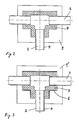
- FIGS. 2 and 3 the pipe joint molding 1 is shown cut after two consecutive process steps of the manufacturing process.
- the pipe joint molding 1 is produced in a combined foaming and casting process in a first mold 9.
- an inner pipe part 4 is inserted with a pipe branch 3.
- the inner tube part 4 may be formed instead of a plastic and metal.
- the free space between the inner tube part 4 and the inner wall of the mold 9 is filled in a first process step with a reactive and closed pore-forming polyurethane foam and foamed.
- the pipe joint molding 1 is brought into a second mold 9 ', which is only slightly larger than the first mold 9.
- the second mold 9' is a second layer 8 of a Polyurethanvergussmasse or other non-or not substantially foaming plastic molding system in the mold 9 'introduced.
- the material for the potting compound of the outer jacket 8 is selected so that the outer jacket 8 exerts only a slight pressure on the insulating layer 7.
- a polyurethane system it is also possible, for example, to choose a polyepoxy system or another thermoplastic system. Basically, with a small difference in the dimensions of the first and the second mold 9,9 'and a single mold with adjustable inner walls feasible.
- the first polyurethane foam layer 7 and the second Polyurethanvergussmasse 8 connect by adhesion to each other and form an insulating jacket 5, on the one hand ensures good thermal insulation and on the other hand sufficient rigidity and strength of the pipe joint molding 1.
- the first polyurethane foam layer 7 is, for example, two to six times as thick as the outer jacket 8 made of a polyurethane casting compound 8 or a casting resin.
- the insulating layer 7 made of polyurethane foam for example, has a density which is substantially less than 10% of the density of the outer jacket 8 of the Polyurethanvergussmasse.
- the pipe joint molding 1 is used for example in piping systems for refrigerant media.
- the pipe joint molding 1 is characterized by a very simple production, because the same plant can be used for the production of the insulating layer and the outer shell. The lowest possible thermal expansion is achieved by using the same materials for the insulating layer and the jacket.
- the outer sheath is waterproof and the pipe joint molding has a high rigidity. Especially in pipe fittings with pipe bends or pipe branches this manufacturing process is time and labor-saving than previous manufacturing process.
- the alignment of the inner tube 4 with respect to the outer shell 8 and / or the transferring in a further form is eliminated.
Description
Die Erfindung bezieht sich auf ein Rohrverbindungsformteil mit thermischer Isolierung umfassend ein Innenrohrteil, eine Dämmschicht und einen Aussenmantel aus Kunststoff, wobei der Aussenmantel und die Dämmschicht aus dem gleichen Werkstoff, beispielsweise Polyurethan, ausgebildet sind.The invention relates to a pipe joint molding with thermal insulation comprising an inner tube part, an insulating layer and an outer sheath made of plastic, wherein the outer sheath and the insulating layer of the same material, such as polyurethane, are formed.
Im Rohrleitungsbau werden, vor allem bei Anwendungen, bei denen eine gute Dämmung des Mediums gegenüber der Umgebung erforderlich ist, wie beispielsweise bei Rohrleitungssysteme für den Transport von Kälteträgermedien, vermehrt vorisolierte Rohrleitungsabschnitte eingesetzt. Ein gut geeignetes Material zur Isolierung von Kälteträgerrohrleitungen ist reaktives geschäumtes Polyurethan (= PUR). Als Schutz vor eindringendem Wasser, welches einen negativen Einfluss auf die Dämmwirkung des Schaums hat, sowie als Schutz vor mechanischen Beschädigungen der Dämmschicht, werden die isolierten Rohrleitungen mit einem Aussenmantel versehen.In piping, especially in applications where a good insulation of the medium to the environment is required, such as piping systems for the transport of refrigerant media, increasingly pre-insulated pipe sections used. A well-suited material for insulating brine pipes is reactive foamed polyurethane (= PUR). As protection against penetrating water, which has a negative influence on the insulating effect of the foam, as well as protection against mechanical damage of the insulating layer, the insulated pipes are provided with an outer jacket.
Um die Rohrleitung wird ein Aussenrohr oder ein rohrförmiger Aussenmantel konzentrisch um die Rohrleitung auf einem gleich bleibenden Abstand zur Aussenwand der Rohrleitung angeordnet. Der ringförmige Raum zwischen der Innenwand des Mantels und der Aussenwand der Rohrleitung wird vollständig mit Polyurethanschaum aufgefüllt. Der Polyurethanschaum wird als reaktive schaumbildende Flüssigkeit eingespritzt und der entstehende Schaum härtet aus. Der Schaum haftet gut an den Oberflächen der Rohrleitung und des Aussenmantels und gibt der so vorisolierten Rohrleitung auch eine höhere Steifigkeit.Around the pipeline, an outer tube or a tubular outer jacket is arranged concentrically around the pipeline at a constant distance from the outer wall of the pipeline. The annular space between the inner wall of the shell and the outer wall of the pipeline is completely filled with polyurethane foam. The polyurethane foam is injected as a reactive foam-forming liquid and the resulting foam cures. The foam adheres well to the surfaces of the piping and the outer jacket and also gives the pipe thus pre-insulated a higher rigidity.
Die Herstellung von vorisolierten Rohrleitungsteilen ist relativ aufwendig, weil mehrere Komponenten mit unterschiedlichen Eigenschaften zusammen gebracht werden müssen. Die Installation von Rohrverzweigungen in vorisolierten Rohrleitungsnetzwerken ist ebenfalls aufwendig, weil in verschiedenen Arbeitsschritten der Isolierungsmantel und die Rohrleitung freigelegt werden müssen, mit der abzweigenden Rohrleitung verbunden und wieder neu isoliert werden müssen.The production of pre-insulated pipe parts is relatively expensive, because several components with different properties must be brought together. The installation of manifolds in pre-insulated Pipe networks is also expensive because in various steps of the insulation jacket and the pipe must be exposed, connected to the branching pipe and re-isolated again.
Aus der
Die
Eine derartige Isolierung eignet sich für Rohre, ist aber für Rohrverbindungen wie Rohrbögen, Rohrkrümmer oder auch Rohrverzweigungen die eine optimale Dämmung erzielen sollen ungenügend, da breite nicht isolierte Bereiche an den Übergängen entstehen.Such insulation is suitable for pipes, but is insufficient for pipe joints such as pipe bends, elbows or pipe branches to achieve optimum insulation, as wide uninsulated areas arise at the transitions.
Die
Dies Isolierungsart, bei der sowohl die innere wie auch die äusseres Schicht aufgeschäumt wird, eignet sich nicht für eine Herstellung von fertig isolierten Rohrverbindungsteilen die schnell und einfach zu montieren sind.This type of insulation, in which both the inner and the outer layer is foamed, is not suitable for the production of completely insulated pipe connection parts which are quick and easy to assemble.
Ausgehend von diesem Stand der Technik ist es Aufgabe der Erfindung, ein Rohrverbindungsformteil mit thermischer Isolierung anzugeben, das auch bei einer verzweigten Rohrleitungsführung einfach hergestellt werden kann, das eine möglichst gute Dämmung gewährleistet, eine möglichst geringe Wärmeausdehnung aufweist, eine hohe Steifigkeit gegen Verformung aufweist und möglichst wasser- und dampfdicht ausgebildet ist. Bei der Herstellung des Rohrverbindungsformteils soll die Dämmschicht von dem Aussenmantel möglichst wenig verdrückt oder beschädigt werden.Based on this prior art, it is an object of the invention to provide a pipe joint molding with thermal insulation, which can be easily produced even with a branched pipe guide, which ensures the best possible insulation, has the lowest possible thermal expansion, has a high rigidity against deformation and is formed as water and vapor-tight as possible. In the manufacture of the pipe joint molding, the insulating layer should be as little as possible pushed or damaged by the outer shell.
Diese Aufgabe wird gelöst durch ein Rohrverbindungsformteil mit thermischer Isolierung umfassend ein Innenrohrteil, eine Dämmschicht und einen Aussenmantel aus Kunststoff, wobei der Aussenmantel und die Dämmschicht aus dem gleichen Werkstoff, beispielsweise Polyurethan, ausgebildet sind, wobei der gegossene Aussenmantel an der Dämmschicht anliegend, mit der Aussenseite der ersten Schaumschicht verbindbar und aus einem im Wesentlichen drucklos vergossenen Werkstoffsystem ausgebildet ist.This object is achieved by a pipe joint molding with thermal insulation comprising an inner tube part, an insulating layer and an outer sheath made of plastic, wherein the outer sheath and the insulating layer of the same material, such as polyurethane, are formed, wherein the cast outer sheath adjacent to the insulating layer, with the Outer side of the first foam layer connectable and formed from a substantially pressureless cast material system.
Die Aufgabe wird auch gelöst durch ein Verfahren zur Herstellung eines Rohrverbindungsformteils gemäss Patentanspruch 12.The object is also achieved by a method for producing a pipe joint molding according to claim 12.
Bevorzugte Weiterbildungen der Erfindung ergeben sich aus den abhängigen Ansprüchen.Preferred developments of the invention will become apparent from the dependent claims.
Es ist von Vorteil, dass das Rohrverbindungsformteil eine möglichst hohe Steifigkeit aufweist. Dies wird dadurch erreicht, dass eine zweite Polyurethanschicht an der ersten Polyurethanschaumschicht anliegend, mit der Aussenseite der ersten Polyurethanschaumschicht verbindbar und aus einem vergiessbaren Polyurethanvergusssystem ausgebildet ist. Dies wird auch dadurch erreicht, dass das Umspritzen des Rohrverbindungsformteils mit der ersten Polyurethanschaumschicht und das Umgiessen der ersten Polyurethanschaumschicht mit der zweiten Polyurethanvergussmasse nach einander in zwei sehr ähnlichen Formen oder in derselben Form auf einer ähnlichen Formanlage durchgeführt werden.It is advantageous that the pipe joint molding has the highest possible rigidity. This is achieved in that a second polyurethane layer adjacent to the first polyurethane foam layer, connectable to the outside of the first polyurethane foam layer and from a pourable Polyurethanvergusssystem is formed. This is also achieved by overmolding the pipe joint molding with the first polyurethane foam layer and casting the first polyurethane foam layer with the second polyurethane casting compound in two very similar forms or shapes on a similar molding line.
Vor allem bei komplizierten Rohrkrümmungen, Rohrbögen und/oder Rohrverzweigungen, die nur mit hohem und oft manuellem Arbeitsaufwand auf verschiedenen Anlagen aus den einzelnen Teilen zusammengesetzt werden mussten, kann durch die Herstellung der Dämmschicht und des Aussenmantels in der selben Anlage viel Zeit und Arbeitsaufwand eingespart werden.Especially in complicated pipe bends, pipe bends and / or pipe branches, which had to be assembled only with high and often manual labor on different systems from the individual parts, can be saved by the production of the insulating layer and the outer shell in the same system much time and effort ,
Ein Ausführungsbeispiel der Erfindung wird anhand der Figuren beschrieben. Es zeigen:
-
Figur 1 einen Schnitt durch ein erfindungsgemässes Rohrverbindungsformteil, -
Figur 2Figur 1 nach einem ersten Verfahrensschritt und -
Figur 3Figur 1 nach einem darauf folgenden Verfahrensschritt.
-
FIG. 1 a section through an inventive pipe joint molding, -
FIG. 2 a section through a mold for producing the pipe joint molding fromFIG. 1 after a first process step and -
FIG. 3 a section through a further mold for the preparation of the pipe joint moldingFIG. 1 after a subsequent process step.
In
Die Isolierung des Rohrverbindungsformteiles 1 ist zusammengesetzt aus einer ersten Polyurethanschaumschicht 7, die aus einem geschlossenporigen Schaum hergestellt ist und einer zweiten Polyurethanschicht 8, die aus einem vergiessbaren Polyurethansystem hergestellt ist. Der Aussenmantel 8 kann auch aus einem anderen unter möglichst niederem Druck vergiessbaren Kunststoffsystem hergestellt werden. Dabei ist vor allem wichtig, dass der Aussenmantel bei der Herstellung, beispielsweise durch Vergiessen, die innere Dämmschicht, das heisst die erste Polyurethanschaumschicht 7, nicht zusammendrückt und nicht beschädigt. Der Aussenmantel 8 soll möglichst wenig Druck auf die Dämmschicht 7 ausüben. Der Aussenmantel 8 kann auch nachträglich in einem Schrumpfverfahren fest mit der ersten Polyurethanschaumschicht 7 verbunden werden. Die Polyurethanschaumschichten 7,8 sind durch Adhäsion fest miteinander verklebt und mit dem Innenrohrteil 4 verbunden. Das Rohrverbindungsformteil 1 wird einstückig hergestellt und weist eine grosse Steifigkeit auf.The insulation of the pipe joint molding 1 is composed of a first
In den
Anschliessend wird, nachdem die erste Polyurethanschaumschicht 7 ausreagiert hat, das Rohrverbindungsformteil 1 in eine zweite Form 9' gebracht, die nur geringfügig grösser ist als die erste Form 9. In der zweiten Form 9' wird eine zweite Schicht 8 aus einer Polyurethanvergussmasse oder einem anderen nicht- oder nicht wesentlich schäumenden Kunststoffgiesssystem in die Form 9' eingebracht. Das Material für die Vergussmasse des Aussenmantels 8 wird so gewählt, dass der Aussenmantel 8 dabei nur einen geringen Druck auf die Dämmschicht 7 ausübt. An Stelle eines Polyurethansystems kann beispielsweise auch ein Polyepoxysystem oder ein anderes thermoplastisches System gewählt werden. Grundsätzlich ist bei einem geringen Unterschied in den Abmessungen der ersten und der zweiten Form 9,9' auch eine einzige Form mit verstellbaren Innenwandungen machbar.Subsequently, after the first polyurethane foam layer has reacted 7, the pipe joint molding 1 is brought into a second mold 9 ', which is only slightly larger than the
Die erste Polyurethanschaumschicht 7 und die zweite Polyurethanvergussmasse 8 verbinden sich durch Adhäsion mit einander und bilden einen Isolierungsmantel 5, der einerseits eine gute thermische Isolierung und andererseits eine ausreichende Steifigkeit und Festigkeit des Rohrverbindungsformteil 1 gewährleistet. Die erste Polyurethanschaumschicht 7 ist beispielsweise zwei- bis sechsmal so dick wie der Aussenmantel 8 aus einer Polyurethanvergussmasse 8 oder einem Giessharz. Die Dämmschicht 7 aus Polyurethanschaum weist beispielsweise eine Dichte auf, die wesentlich weniger als 10% der Dichte des Aussenmantels 8 aus der Polyurethanvergussmasse beträgt.The first
Das Rohrverbindungsformteil 1 wird beispielsweise in Rohrleitungssysteme für Kälteträgermedien verwendet. Das Rohrverbindungsformteil 1 zeichnet sich aus durch eine sehr einfache Herstellung, weil für die Herstellung der Dämmschicht und des Aussenmantels dieselbe Anlage verwendet werden kann. Eine möglichst geringe Wärmeausdehnung wird erreicht durch die Verwendung der gleichen Werkstoffe für Dämmschicht und Mantel. Der Aussenmantel ist wasserdicht und das Rohrverbindungsformteil weist eine hohe Steifigkeit auf. Vor allem bei Rohrverbindungsformteile mit Rohrkrümmungen oder Rohrverzweigungen ist dieses Herstellungsverfahren zeit- und arbeitssparender als bisherigen Herstellungsverfahren. Das Ausrichten des Innenrohres 4 in Bezug auf den Aussenmantel 8 und/oder das Überbringen in einer weiteren Form entfällt. DasThe pipe joint molding 1 is used for example in piping systems for refrigerant media. The pipe joint molding 1 is characterized by a very simple production, because the same plant can be used for the production of the insulating layer and the outer shell. The lowest possible thermal expansion is achieved by using the same materials for the insulating layer and the jacket. The outer sheath is waterproof and the pipe joint molding has a high rigidity. Especially in pipe fittings with pipe bends or pipe branches this manufacturing process is time and labor-saving than previous manufacturing process. The alignment of the
Schrumpfen des Schrumpfschlauches auf einer Schrumpfanlage entfällt.Shrinkage of the shrink tubing on a shrinking plant is eliminated.
Claims (12)
- Pipe-connection moulded part (1) having thermal insulation, comprising an inner pipe part (4), an insulating layer (7) and an outer casing (8) of plastic, wherein the outer casing (8) and the insulating layer (7) are formed from the same material, for example polyurethane, characterized in that the cast outer casing (8) is in contact with the insulating layer (7), can be connected to the outer side of the first foam layer (7) and is formed from a material system poured in an essentially pressureless manner.
- Pipe-connection moulded part (1) having thermal insulation according to Claim 1, characterized in that the insulating layer (7) is in contact with the inner pipe part (4), can be connected to the outer side of the inner pipe part (4) and is formed from a foam system.
- Pipe-connection moulded part (1) having thermal insulation according to at least one of Claims 1 and 2, characterized in that the insulating layer (7) is in contact with the inner pipe part (4), can be connected to the outer side of the inner pipe part (4) and is formed from a closed-cell polyurethane foam system.
- Pipe-connection moulded part (1) having thermal insulation according to at least one of Claims 1 to 3, characterized in that the outer casing (8) is formed from a pourable material compatible with the insulating layer.
- Pipe-connection moulded part (1) having thermal insulation according to at least one of Claims 1 to 4, characterized in that the outer casing (8) is in contact with the insulating layer (7), can be connected to the outer side of the first foam layer (7) and is formed from a pourable casting system which does foam to a considerable degree.
- Pipe-connection moulded part (1) having thermal insulation according to at least one of Claims 1 to 5, characterized in that the outer casing (8) is in contact with the insulating layer (7), can be connected to the outer side of the first foam layer (7) and is formed from a pourable polyurethane casting system which does not foam to a considerable degree.
- Pipe-connection moulded part (1) having thermal insulation according to at least one of Claims 1 to 6, characterized in that the inner pipe part (4) is formed from an acrylonitrile-butadiene-styrene copolymer (= ABS).
- Pipe-connection moulded part (1) having thermal insulation according to at least one of Claims 1 to 7, characterized in that the inner pipe part (4) is formed from any desired plastic, for example polyethylene, polypropylene or polyvinylchloride.
- Pipe-connection moulded part (1) having thermal insulation according to at least one of Claims 1 to 8, characterized in that the pipe-connection moulded part (1) has at least one pipe branch.
- Pipe-connection moulded part (1) having thermal insulation according to at least one of Claims 1 to 9, characterized in that the pipe-connection moulded part (1) has at least one pipe elbow.
- Method of producing a pipe-connection moulded part (1) having thermal insulation according to at least one of Claims 1 to 10, comprising at least the following method steps:a) inserting the inner pipe part (4) into a first mould (9),b) foam-encapsulating the inner pipe part (4) with a first insulating layer (7), consisting of a foam system, for example a closed-cell polyurethane foam system,c) inserting the foam-encapsulated inner pipe part (4) with the insulating layer (7) in a second mould (9') which is slightly larger than the first mould (9), andd) casting an outer casing (8) in an essentially pressureless manner around the insulating layer (7), said outer casing (8) consisting of a pourable, non-foaming material system compatible with the insulating layer (7) producing a low internal tool pressure, without the insulating layer (7) being damaged or compressed by the outer casing (8) in the process..
- Method of producing a pipe-connection moulded part (1) having thermal insulation according to Claim 11, characterized in that the method steps b), c) and d) are carried out successively in the same mould.
Priority Applications (4)
| Application Number | Priority Date | Filing Date | Title |
|---|---|---|---|
| EP06123155.1A EP1909018B1 (en) | 2006-10-05 | 2006-10-30 | Pipe connection with thermal insulation and procedure for the manufacture of the pipe connecting part |
| AU2007216715A AU2007216715B2 (en) | 2006-10-05 | 2007-09-11 | Pipe-connection moulded part having thermal insulation and method of producing the pipe-connection moulded part |
| US11/865,733 US20080084059A1 (en) | 2006-10-05 | 2007-10-02 | Pipe-connection moulded part having thermal insulation and method of producing the pipe-connection moulded part |
| JP2007261229A JP5629046B2 (en) | 2006-10-05 | 2007-10-04 | Method for manufacturing pipe joint molded member having heat insulating material |
Applications Claiming Priority (2)
| Application Number | Priority Date | Filing Date | Title |
|---|---|---|---|
| EP06121797 | 2006-10-05 | ||
| EP06123155.1A EP1909018B1 (en) | 2006-10-05 | 2006-10-30 | Pipe connection with thermal insulation and procedure for the manufacture of the pipe connecting part |
Publications (3)
| Publication Number | Publication Date |
|---|---|
| EP1909018A2 EP1909018A2 (en) | 2008-04-09 |
| EP1909018A3 EP1909018A3 (en) | 2009-09-23 |
| EP1909018B1 true EP1909018B1 (en) | 2014-08-20 |
Family
ID=38982526
Family Applications (1)
| Application Number | Title | Priority Date | Filing Date |
|---|---|---|---|
| EP06123155.1A Active EP1909018B1 (en) | 2006-10-05 | 2006-10-30 | Pipe connection with thermal insulation and procedure for the manufacture of the pipe connecting part |
Country Status (4)
| Country | Link |
|---|---|
| US (1) | US20080084059A1 (en) |
| EP (1) | EP1909018B1 (en) |
| JP (1) | JP5629046B2 (en) |
| AU (1) | AU2007216715B2 (en) |
Cited By (1)
| Publication number | Priority date | Publication date | Assignee | Title |
|---|---|---|---|---|
| EP3031599A1 (en) | 2014-12-11 | 2016-06-15 | Georg Fischer Rohrleitungssysteme AG | Insulated electrofusion fitting |
Families Citing this family (4)
| Publication number | Priority date | Publication date | Assignee | Title |
|---|---|---|---|---|
| JP2017025967A (en) * | 2015-07-17 | 2017-02-02 | ハジメ産業株式会社 | Shell |
| JP6709080B2 (en) * | 2016-03-02 | 2020-06-10 | 積水化学工業株式会社 | Foam pipe fittings |
| JP6885767B2 (en) * | 2017-03-30 | 2021-06-16 | 積水化学工業株式会社 | Pipe fitting |
| TW202041348A (en) * | 2019-03-22 | 2020-11-16 | 日商積水化學工業股份有限公司 | Pipe joint and piping structure |
Citations (1)
| Publication number | Priority date | Publication date | Assignee | Title |
|---|---|---|---|---|
| EP1584460A1 (en) * | 2004-03-15 | 2005-10-12 | Poloplast GmbH & Co. KG | Plastic pipe resp. pipe fitting |
Family Cites Families (29)
| Publication number | Priority date | Publication date | Assignee | Title |
|---|---|---|---|---|
| JPS433176Y1 (en) * | 1965-06-24 | 1968-02-09 | ||
| US3402731A (en) * | 1965-08-11 | 1968-09-24 | American Standard Inc | Piping systems |
| US3744823A (en) * | 1971-03-01 | 1973-07-10 | Shaw Pipe Ind Ltd | High temperature pipeline joints |
| GB1477074A (en) * | 1975-01-31 | 1977-06-22 | Hepworth Iron Co Ltd | Manufacture of pipe couplings |
| FR2402151A2 (en) * | 1977-09-05 | 1979-03-30 | Pont A Mousson | LARGE DIAMETER HEAT PIPE |
| DE2714576C2 (en) * | 1977-04-01 | 1983-11-17 | Wavin B.V., 8031 Zwolle | Plastic pipe part for drainage pipe systems |
| US4236736A (en) * | 1978-05-01 | 1980-12-02 | Turnbuckle Products Corporation | Hose coupling |
| GB2046865B (en) * | 1979-03-15 | 1983-06-15 | Kendall & Co | Insulation of pipe by multi-stage application of foam |
| US4303458A (en) * | 1980-02-19 | 1981-12-01 | Gambro Ab | Method of joining conduits with a connecting piece and connecting piece for use in the method |
| NL8005161A (en) * | 1980-09-15 | 1982-04-01 | Wavin Bv | GLUED TUBE CONNECTION. |
| NL8100776A (en) * | 1981-02-17 | 1982-09-16 | Wavin Bv | INSULATION TUBE PART, AND INSULATED TUBE CONNECTION. |
| JPS58128599A (en) * | 1982-01-26 | 1983-08-01 | 株式会社クボタ | Heat-insulating special-form pipe |
| US4484386A (en) * | 1982-11-01 | 1984-11-27 | Rovanco Corp. | Method of field insulating pipe joints |
| DE3370680D1 (en) * | 1982-12-23 | 1987-05-07 | Webco Ind Rubber Ltd | Insulated pipeline |
| JPS59166796A (en) * | 1982-12-23 | 1984-09-20 | ウエブコ・インダストリアル・ラバ−・リミテイド | Heat-insulating pipeline |
| JPS59146125U (en) * | 1983-03-22 | 1984-09-29 | 加藤 裕三 | Multilayer pipe with excellent insulation, heat retention, and cold retention properties |
| FR2563608B1 (en) * | 1984-04-25 | 1986-11-07 | Coflexip | INSULATED PIPE FOR THE TRANSPORT OF FLUIDS |
| DE3447393A1 (en) * | 1984-12-24 | 1986-07-03 | kabelmetal electro GmbH, 3000 Hannover | Method for producing a junction on a laid pipeline |
| US4804210A (en) * | 1987-06-15 | 1989-02-14 | Hancock James W | Double sealed, double wall insulated SPA pipe coupling |
| DE3822090C1 (en) * | 1988-06-30 | 1989-07-27 | Bayer Ag, 5090 Leverkusen, De | |
| JP2795485B2 (en) * | 1989-10-06 | 1998-09-10 | 古河電気工業株式会社 | Indoor plumbing materials, their connection members and plumbing methods |
| EP0532459B1 (en) * | 1991-09-06 | 1996-10-23 | Hobas Engineering AG | Junction sleeve for two plastic pipes. |
| US5681459A (en) * | 1994-03-07 | 1997-10-28 | Bowman; Dennis E. | Refect water drain line installation system and apparatus for under sink reverse osmosis filter system |
| US5900195A (en) * | 1996-08-12 | 1999-05-04 | Urethane Products International | Protection of pipeline joint connections |
| JP3137937B2 (en) * | 1997-11-25 | 2001-02-26 | 神戸樹脂工業株式会社 | Cladding fittings |
| JP3699579B2 (en) * | 1998-01-13 | 2005-09-28 | 積水化学工業株式会社 | Pipe joint with heat insulation layer and method for producing the same |
| GB9905037D0 (en) * | 1999-03-05 | 1999-04-28 | Raychem Sa Nv | Method of sealing a joint between two pipes |
| US6315006B1 (en) * | 2001-02-12 | 2001-11-13 | Hydra-Zorb, Co. | Pipe insulation coupling |
| DE10225802A1 (en) * | 2002-06-10 | 2003-12-24 | Fischer Georg Rohrleitung | Pipe joint molding for pre-insulated piping |
-
2006
- 2006-10-30 EP EP06123155.1A patent/EP1909018B1/en active Active
-
2007
- 2007-09-11 AU AU2007216715A patent/AU2007216715B2/en active Active
- 2007-10-02 US US11/865,733 patent/US20080084059A1/en not_active Abandoned
- 2007-10-04 JP JP2007261229A patent/JP5629046B2/en active Active
Patent Citations (1)
| Publication number | Priority date | Publication date | Assignee | Title |
|---|---|---|---|---|
| EP1584460A1 (en) * | 2004-03-15 | 2005-10-12 | Poloplast GmbH & Co. KG | Plastic pipe resp. pipe fitting |
Cited By (1)
| Publication number | Priority date | Publication date | Assignee | Title |
|---|---|---|---|---|
| EP3031599A1 (en) | 2014-12-11 | 2016-06-15 | Georg Fischer Rohrleitungssysteme AG | Insulated electrofusion fitting |
Also Published As
| Publication number | Publication date |
|---|---|
| EP1909018A3 (en) | 2009-09-23 |
| EP1909018A2 (en) | 2008-04-09 |
| AU2007216715A1 (en) | 2008-04-24 |
| AU2007216715B2 (en) | 2010-07-08 |
| JP5629046B2 (en) | 2014-11-19 |
| US20080084059A1 (en) | 2008-04-10 |
| JP2008095956A (en) | 2008-04-24 |
Similar Documents
| Publication | Publication Date | Title |
|---|---|---|
| EP1909018B1 (en) | Pipe connection with thermal insulation and procedure for the manufacture of the pipe connecting part | |
| CH631533A5 (en) | FORM-FITTED PIPE CONNECTION AND METHOD FOR THEIR PRODUCTION. | |
| CH662086A5 (en) | METHOD FOR PRODUCING INSULATED PIPELINE PARTS. | |
| DE2537251A1 (en) | PROCESS AND MOLDING CORE FOR MANUFACTURING A MULTI-SIDED, FLEXIBLE HOLLOW-SHAPED BODY | |
| DE19510490A1 (en) | Insulation for heat storage bodies and piping for high flexibility | |
| DE19600249A1 (en) | Pipe insulation kit composed of parts and method of manufacturing such parts | |
| WO1997043576A1 (en) | Process for manufacturing individual pipe sections of a pipe system, and pipe system manufactured in said manner | |
| CH660907A5 (en) | HEAT-INSULATED PIPE AND METHOD FOR THE PRODUCTION THEREOF. | |
| EP2137451B1 (en) | Plastic tube | |
| EP1471299A1 (en) | Thermally insulated pipe | |
| DE4402984C2 (en) | Process for the production of pipelines | |
| EP1511960B2 (en) | Pipe-connector moulded part for pre-insulated pipe conduits | |
| DE2824906C2 (en) | Process for the production of heat-insulated conduit pipes | |
| DE3300443A1 (en) | Foam-filled half-shells with solid outer wall for pipe insulation and process for the manufacture thereof | |
| DE1228468B (en) | Flexible pipeline and process for making same | |
| EP2060842B1 (en) | Connecting component | |
| DE2804645C2 (en) | Pipe with a plastic sleeve and process for its manufacture | |
| DE7837633U1 (en) | PIPE CLAMP FOR PIPES CARRYING COLD MATERIALS | |
| DE3534174C2 (en) | ||
| DE4130167A1 (en) | Chemical fluid or diffusion resistant composite tube e.g. for potable water pipe | |
| DE3921174C2 (en) | ||
| DE2527838A1 (en) | Rapid pipe join making system - uses length of heat shrinking material over ends of tubes to be connected | |
| WO2008113805A1 (en) | Pressure piping | |
| DE2320177C3 (en) | Conical screw connection of plastic pipes | |
| DE1679946A1 (en) | Method of manufacturing ball valves |
Legal Events
| Date | Code | Title | Description |
|---|---|---|---|
| PUAI | Public reference made under article 153(3) epc to a published international application that has entered the european phase |
Free format text: ORIGINAL CODE: 0009012 |
|
| AK | Designated contracting states |
Kind code of ref document: A2 Designated state(s): AT BE BG CH CY CZ DE DK EE ES FI FR GB GR HU IE IS IT LI LT LU LV MC NL PL PT RO SE SI SK TR |
|
| AX | Request for extension of the european patent |
Extension state: AL BA HR MK RS |
|
| PUAL | Search report despatched |
Free format text: ORIGINAL CODE: 0009013 |
|
| AK | Designated contracting states |
Kind code of ref document: A3 Designated state(s): AT BE BG CH CY CZ DE DK EE ES FI FR GB GR HU IE IS IT LI LT LU LV MC NL PL PT RO SE SI SK TR |
|
| AX | Request for extension of the european patent |
Extension state: AL BA HR MK RS |
|
| 17P | Request for examination filed |
Effective date: 20100319 |
|
| 17Q | First examination report despatched |
Effective date: 20100422 |
|
| AKX | Designation fees paid |
Designated state(s): AT BE BG CH CY CZ DE DK EE ES FI FR GB GR HU IE IS IT LI LT LU LV MC NL PL PT RO SE SI SK TR |
|
| GRAP | Despatch of communication of intention to grant a patent |
Free format text: ORIGINAL CODE: EPIDOSNIGR1 |
|
| INTG | Intention to grant announced |
Effective date: 20140414 |
|
| INTG | Intention to grant announced |
Effective date: 20140424 |
|
| GRAS | Grant fee paid |
Free format text: ORIGINAL CODE: EPIDOSNIGR3 |
|
| GRAA | (expected) grant |
Free format text: ORIGINAL CODE: 0009210 |
|
| AK | Designated contracting states |
Kind code of ref document: B1 Designated state(s): AT BE BG CH CY CZ DE DK EE ES FI FR GB GR HU IE IS IT LI LT LU LV MC NL PL PT RO SE SI SK TR |
|
| REG | Reference to a national code |
Ref country code: GB Ref legal event code: FG4D Free format text: NOT ENGLISH |
|
| REG | Reference to a national code |
Ref country code: CH Ref legal event code: NV Representative=s name: GEORG FISCHER AG, CH Ref country code: CH Ref legal event code: EP |
|
| REG | Reference to a national code |
Ref country code: AT Ref legal event code: REF Ref document number: 683669 Country of ref document: AT Kind code of ref document: T Effective date: 20140915 |
|
| REG | Reference to a national code |
Ref country code: IE Ref legal event code: FG4D Free format text: LANGUAGE OF EP DOCUMENT: GERMAN |
|
| REG | Reference to a national code |
Ref country code: DE Ref legal event code: R096 Ref document number: 502006013922 Country of ref document: DE Effective date: 20141002 |
|
| REG | Reference to a national code |
Ref country code: DK Ref legal event code: T3 Effective date: 20141029 |
|
| REG | Reference to a national code |
Ref country code: NL Ref legal event code: T3 |
|
| REG | Reference to a national code |
Ref country code: LT Ref legal event code: MG4D |
|
| PG25 | Lapsed in a contracting state [announced via postgrant information from national office to epo] |
Ref country code: GR Free format text: LAPSE BECAUSE OF FAILURE TO SUBMIT A TRANSLATION OF THE DESCRIPTION OR TO PAY THE FEE WITHIN THE PRESCRIBED TIME-LIMIT Effective date: 20141121 Ref country code: LT Free format text: LAPSE BECAUSE OF FAILURE TO SUBMIT A TRANSLATION OF THE DESCRIPTION OR TO PAY THE FEE WITHIN THE PRESCRIBED TIME-LIMIT Effective date: 20140820 Ref country code: SE Free format text: LAPSE BECAUSE OF FAILURE TO SUBMIT A TRANSLATION OF THE DESCRIPTION OR TO PAY THE FEE WITHIN THE PRESCRIBED TIME-LIMIT Effective date: 20140820 Ref country code: BG Free format text: LAPSE BECAUSE OF FAILURE TO SUBMIT A TRANSLATION OF THE DESCRIPTION OR TO PAY THE FEE WITHIN THE PRESCRIBED TIME-LIMIT Effective date: 20141120 Ref country code: FI Free format text: LAPSE BECAUSE OF FAILURE TO SUBMIT A TRANSLATION OF THE DESCRIPTION OR TO PAY THE FEE WITHIN THE PRESCRIBED TIME-LIMIT Effective date: 20140820 Ref country code: PT Free format text: LAPSE BECAUSE OF FAILURE TO SUBMIT A TRANSLATION OF THE DESCRIPTION OR TO PAY THE FEE WITHIN THE PRESCRIBED TIME-LIMIT Effective date: 20141222 Ref country code: ES Free format text: LAPSE BECAUSE OF FAILURE TO SUBMIT A TRANSLATION OF THE DESCRIPTION OR TO PAY THE FEE WITHIN THE PRESCRIBED TIME-LIMIT Effective date: 20140820 |
|
| PG25 | Lapsed in a contracting state [announced via postgrant information from national office to epo] |
Ref country code: LV Free format text: LAPSE BECAUSE OF FAILURE TO SUBMIT A TRANSLATION OF THE DESCRIPTION OR TO PAY THE FEE WITHIN THE PRESCRIBED TIME-LIMIT Effective date: 20140820 |
|
| PG25 | Lapsed in a contracting state [announced via postgrant information from national office to epo] |
Ref country code: CZ Free format text: LAPSE BECAUSE OF FAILURE TO SUBMIT A TRANSLATION OF THE DESCRIPTION OR TO PAY THE FEE WITHIN THE PRESCRIBED TIME-LIMIT Effective date: 20140820 Ref country code: SK Free format text: LAPSE BECAUSE OF FAILURE TO SUBMIT A TRANSLATION OF THE DESCRIPTION OR TO PAY THE FEE WITHIN THE PRESCRIBED TIME-LIMIT Effective date: 20140820 Ref country code: EE Free format text: LAPSE BECAUSE OF FAILURE TO SUBMIT A TRANSLATION OF THE DESCRIPTION OR TO PAY THE FEE WITHIN THE PRESCRIBED TIME-LIMIT Effective date: 20140820 Ref country code: RO Free format text: LAPSE BECAUSE OF FAILURE TO SUBMIT A TRANSLATION OF THE DESCRIPTION OR TO PAY THE FEE WITHIN THE PRESCRIBED TIME-LIMIT Effective date: 20140820 |
|
| REG | Reference to a national code |
Ref country code: DE Ref legal event code: R097 Ref document number: 502006013922 Country of ref document: DE |
|
| PG25 | Lapsed in a contracting state [announced via postgrant information from national office to epo] |
Ref country code: PL Free format text: LAPSE BECAUSE OF FAILURE TO SUBMIT A TRANSLATION OF THE DESCRIPTION OR TO PAY THE FEE WITHIN THE PRESCRIBED TIME-LIMIT Effective date: 20140820 Ref country code: LU Free format text: LAPSE BECAUSE OF FAILURE TO SUBMIT A TRANSLATION OF THE DESCRIPTION OR TO PAY THE FEE WITHIN THE PRESCRIBED TIME-LIMIT Effective date: 20141030 Ref country code: MC Free format text: LAPSE BECAUSE OF FAILURE TO SUBMIT A TRANSLATION OF THE DESCRIPTION OR TO PAY THE FEE WITHIN THE PRESCRIBED TIME-LIMIT Effective date: 20140820 |
|
| PLBE | No opposition filed within time limit |
Free format text: ORIGINAL CODE: 0009261 |
|
| STAA | Information on the status of an ep patent application or granted ep patent |
Free format text: STATUS: NO OPPOSITION FILED WITHIN TIME LIMIT |
|
| PG25 | Lapsed in a contracting state [announced via postgrant information from national office to epo] |
Ref country code: BE Free format text: LAPSE BECAUSE OF NON-PAYMENT OF DUE FEES Effective date: 20141031 |
|
| 26N | No opposition filed |
Effective date: 20150521 |
|
| REG | Reference to a national code |
Ref country code: IE Ref legal event code: MM4A |
|
| REG | Reference to a national code |
Ref country code: FR Ref legal event code: PLFP Year of fee payment: 10 |
|
| PG25 | Lapsed in a contracting state [announced via postgrant information from national office to epo] |
Ref country code: IE Free format text: LAPSE BECAUSE OF NON-PAYMENT OF DUE FEES Effective date: 20141030 |
|
| PG25 | Lapsed in a contracting state [announced via postgrant information from national office to epo] |
Ref country code: SI Free format text: LAPSE BECAUSE OF FAILURE TO SUBMIT A TRANSLATION OF THE DESCRIPTION OR TO PAY THE FEE WITHIN THE PRESCRIBED TIME-LIMIT Effective date: 20140820 |
|
| PG25 | Lapsed in a contracting state [announced via postgrant information from national office to epo] |
Ref country code: CY Free format text: LAPSE BECAUSE OF FAILURE TO SUBMIT A TRANSLATION OF THE DESCRIPTION OR TO PAY THE FEE WITHIN THE PRESCRIBED TIME-LIMIT Effective date: 20140820 |
|
| PG25 | Lapsed in a contracting state [announced via postgrant information from national office to epo] |
Ref country code: HU Free format text: LAPSE BECAUSE OF FAILURE TO SUBMIT A TRANSLATION OF THE DESCRIPTION OR TO PAY THE FEE WITHIN THE PRESCRIBED TIME-LIMIT; INVALID AB INITIO Effective date: 20061030 |
|
| REG | Reference to a national code |
Ref country code: FR Ref legal event code: PLFP Year of fee payment: 11 |
|
| REG | Reference to a national code |
Ref country code: FR Ref legal event code: PLFP Year of fee payment: 12 |
|
| REG | Reference to a national code |
Ref country code: FR Ref legal event code: PLFP Year of fee payment: 13 |
|
| PGFP | Annual fee paid to national office [announced via postgrant information from national office to epo] |
Ref country code: NL Payment date: 20191021 Year of fee payment: 14 |
|
| PGFP | Annual fee paid to national office [announced via postgrant information from national office to epo] |
Ref country code: FR Payment date: 20191028 Year of fee payment: 14 |
|
| PGFP | Annual fee paid to national office [announced via postgrant information from national office to epo] |
Ref country code: AT Payment date: 20191022 Year of fee payment: 14 Ref country code: TR Payment date: 20191021 Year of fee payment: 14 |
|
| PGFP | Annual fee paid to national office [announced via postgrant information from national office to epo] |
Ref country code: GB Payment date: 20191021 Year of fee payment: 14 |
|
| PGFP | Annual fee paid to national office [announced via postgrant information from national office to epo] |
Ref country code: IS Payment date: 20200121 Year of fee payment: 14 |
|
| REG | Reference to a national code |
Ref country code: NL Ref legal event code: MM Effective date: 20201101 |
|
| REG | Reference to a national code |
Ref country code: AT Ref legal event code: MM01 Ref document number: 683669 Country of ref document: AT Kind code of ref document: T Effective date: 20201030 |
|
| GBPC | Gb: european patent ceased through non-payment of renewal fee |
Effective date: 20201030 |
|
| PG25 | Lapsed in a contracting state [announced via postgrant information from national office to epo] |
Ref country code: FR Free format text: LAPSE BECAUSE OF NON-PAYMENT OF DUE FEES Effective date: 20201031 Ref country code: NL Free format text: LAPSE BECAUSE OF NON-PAYMENT OF DUE FEES Effective date: 20201101 |
|
| PG25 | Lapsed in a contracting state [announced via postgrant information from national office to epo] |
Ref country code: AT Free format text: LAPSE BECAUSE OF NON-PAYMENT OF DUE FEES Effective date: 20201030 Ref country code: GB Free format text: LAPSE BECAUSE OF NON-PAYMENT OF DUE FEES Effective date: 20201030 |
|
| PG25 | Lapsed in a contracting state [announced via postgrant information from national office to epo] |
Ref country code: TR Free format text: LAPSE BECAUSE OF NON-PAYMENT OF DUE FEES Effective date: 20201030 |
|
| P01 | Opt-out of the competence of the unified patent court (upc) registered |
Effective date: 20230529 |
|
| PGFP | Annual fee paid to national office [announced via postgrant information from national office to epo] |
Ref country code: IT Payment date: 20231026 Year of fee payment: 18 Ref country code: DK Payment date: 20231024 Year of fee payment: 18 Ref country code: DE Payment date: 20231020 Year of fee payment: 18 Ref country code: CH Payment date: 20231102 Year of fee payment: 18 |