EP1907310B1 - Trailer for a motor vehicle - Google Patents
Trailer for a motor vehicle Download PDFInfo
- Publication number
- EP1907310B1 EP1907310B1 EP05740666A EP05740666A EP1907310B1 EP 1907310 B1 EP1907310 B1 EP 1907310B1 EP 05740666 A EP05740666 A EP 05740666A EP 05740666 A EP05740666 A EP 05740666A EP 1907310 B1 EP1907310 B1 EP 1907310B1
- Authority
- EP
- European Patent Office
- Prior art keywords
- trailer
- forklift device
- hubstaplervorrichtung
- frame
- wheels
- Prior art date
- Legal status (The legal status is an assumption and is not a legal conclusion. Google has not performed a legal analysis and makes no representation as to the accuracy of the status listed.)
- Active
Links
Images


Classifications
-
- B—PERFORMING OPERATIONS; TRANSPORTING
- B66—HOISTING; LIFTING; HAULING
- B66F—HOISTING, LIFTING, HAULING OR PUSHING, NOT OTHERWISE PROVIDED FOR, e.g. DEVICES WHICH APPLY A LIFTING OR PUSHING FORCE DIRECTLY TO THE SURFACE OF A LOAD
- B66F9/00—Devices for lifting or lowering bulky or heavy goods for loading or unloading purposes
- B66F9/06—Devices for lifting or lowering bulky or heavy goods for loading or unloading purposes movable, with their loads, on wheels or the like, e.g. fork-lift trucks
- B66F9/075—Constructional features or details
- B66F9/08—Masts; Guides; Chains
- B66F9/10—Masts; Guides; Chains movable in a horizontal direction relative to truck
-
- B—PERFORMING OPERATIONS; TRANSPORTING
- B60—VEHICLES IN GENERAL
- B60P—VEHICLES ADAPTED FOR LOAD TRANSPORTATION OR TO TRANSPORT, TO CARRY, OR TO COMPRISE SPECIAL LOADS OR OBJECTS
- B60P1/00—Vehicles predominantly for transporting loads and modified to facilitate loading, consolidating the load, or unloading
- B60P1/02—Vehicles predominantly for transporting loads and modified to facilitate loading, consolidating the load, or unloading with parallel up-and-down movement of load supporting or containing element
- B60P1/025—Vehicles predominantly for transporting loads and modified to facilitate loading, consolidating the load, or unloading with parallel up-and-down movement of load supporting or containing element with a loading platform inside the wheels of a same axle and being lowerable below the axle
-
- B—PERFORMING OPERATIONS; TRANSPORTING
- B62—LAND VEHICLES FOR TRAVELLING OTHERWISE THAN ON RAILS
- B62D—MOTOR VEHICLES; TRAILERS
- B62D63/00—Motor vehicles or trailers not otherwise provided for
- B62D63/06—Trailers
-
- B—PERFORMING OPERATIONS; TRANSPORTING
- B66—HOISTING; LIFTING; HAULING
- B66F—HOISTING, LIFTING, HAULING OR PUSHING, NOT OTHERWISE PROVIDED FOR, e.g. DEVICES WHICH APPLY A LIFTING OR PUSHING FORCE DIRECTLY TO THE SURFACE OF A LOAD
- B66F9/00—Devices for lifting or lowering bulky or heavy goods for loading or unloading purposes
- B66F9/06—Devices for lifting or lowering bulky or heavy goods for loading or unloading purposes movable, with their loads, on wheels or the like, e.g. fork-lift trucks
Definitions
- the invention relates to a two-axle trailer for a motor vehicle with a trailer frame, on the frame longitudinal elements two longitudinally spaced pairs of wheels are arranged, and a mounted inside the trailer Hubstaplervor substances which Hubstaplervortechnisch within the trailer between a transposition, in the load can be transported, and a loading position in the load with the Hubstaplervorlase is raised and lowered, is displaceable, wherein at least one cross-connecting element is provided which connects the frame longitudinal elements in the wheels, and that the loading position of the Hubstaplervortechnisch - in the direction of travel Seen - is located immediately behind the at least one cross-connecting element, so that the Hubstaplervortechnisch is lowered to the ground level on which the trailer is.
- GB 2 145 995 A For example, there is shown a uniaxial U-shaped frame trailer and a lift truck apparatus having longitudinally extending fork arms for receiving cargo.
- the GB 2 153 339 A describes a uniaxial forklift trailer for agricultural tractors whose frame is composed essentially of two longitudinal elements and two cross-connection elements for the displaceable between a transport position and a loading position forklift device a corresponding counterweight is provided on the trailer drawbar, which compensates for the overturning moments occurring during loading , while driving is to be carried as an additional load from the trailer hitch.
- the forklift device can be lowered to the floor behind the cross connection elements in order to be able to pick up the load to be transported.
- a trailer is shown with a horizontally movable Hubstaplervorraum for carrying out loading work, which has a U-shaped trailer frame.
- Hubstaplervoriques By integrated in the trailer Hubstaplervoriques the transport of eg only a pallet of building material can be done very efficiently by this pallet can be delivered to the trailer and then unloaded with the Hubstaplervorides, without the need for a separate crane or forklift on site. Regardless of whether at the place of delivery mechanical charging devices are present or not, so can the Transporting the load and unloading or loading can be done very quickly. For example, if additional material is required on a construction site, this can be picked up immediately from a hardware store, without having to take account of order times and freight costs.
- the Hubstaplervoriques can be brought into a loading position in which the Hubstaplervortechnische can be lowered to the ground level.
- the wheels are not mounted on a continuous axis but on stub axles on the sides of the trailer. In this way, this type of trailer can be built only with an excess width, which limits the usability.
- a relatively heavy construction if sufficient rigidity should be ensured, but this has a negative impact on the fuel consumption of the towing vehicle and on its driving characteristics.
- a trailer for receiving pallets in which a lifting bar is movably mounted by means of a chain conveyor, so that a pallet is brought by means of introduced support rods from a front trailer area behind the trailer axles and then lowered to ground level.
- the loading area is composed of a fixed and a movable loading floor, wherein the fixed loading floor is held in a square profile of the trailer frame, which includes a cross-connection between two longitudinal profiles in the region of the wheel axles.
- the object of the invention is therefore to provide a trailer of the type mentioned, with the loads of small extent can be transported so that a loading and unloading of the trailer with little effort and time is possible, the trailer but sufficient stability with low weight having.
- Another object of the invention is to provide a trailer that can be realized by simple technical means.
- the ale hollow profiles formed cross-connection elements provide increased trailer stability and also serve the wheel bearing and shock absorption. In this way, a very small width can be achieved.
- the available standing space in the trailer according to the invention are advantageously used in that the Hubstaplervoropathy is in transport position substantially in the front region of the trailer and in Verladerium substantially in the region of the or the cross-connecting element (s) or the wheel axle (s) of the trailer, wherein the Hubstaplervortechnisch in Verlade ein behind the rear cross-member and the rear axle to the ground level on which the trailer is lowered.
- the bottom wall of the trailer be at least partially removable, so that the Hubstaplervorides in the region of the at least one cross-connecting element is movable up and down.
- the bottom wall may be composed of a fixed bottom wall portion extending from the front trailer portion to the cross member (s) and a removable bottom wall portion extending from the cross tie member (s) to the rear trailer wall.
- the removable in this way bottom wall part can be removed during loading operations from the trailer according to the invention and then the Hubstaplervorraum be brought to the transition between the fixed bottom wall element and the now open bottom wall portion to perform the upward and downward movement of the Hubstaplerelements can.
- a development of the invention may consist in that the Hubstaplervoriques has a vertically movable forklift fork, preferably with two parallel fork arms.
- Standardized load elements such as pallets or the like, as well as bulk material devices or concrete mixers, which have suitable fork slots, can be loaded onto or unloaded from the trailer according to the invention in a simple manner by means of the forklift fork.
- the distance between the fork arms may be adjustable so that an adaptation to different charging devices can be made.
- an alignment of the fork arms in the longitudinal direction of the trailer should be strived for.
- a loading and unloading of the trailer from the back of the trailer is preferred, with the free ends of the fork arms are preferably oriented opposite to the direction of travel of the trailer. It can be arranged differently according to the respective requirements, the fork arms.
- the mobility of the Hubstaplervoriques of the trailer according to the invention can be done in various ways, according to an embodiment of the invention, the Hubstaplervor Vietnamese ajar, ajar, a jar, a jar, a jar, a jar, a jar, a styrene-maleic anhydride (PAS), a styrene-maleic anhydride (PAS), a staplervortechnische, a low-friction movement is possible and on the other hand, this provides a stable support to absorb the forces and tilting moments effective during a loading process can.
- a horizontally movable, hydraulically driven horizontal carriage which is reciprocated between the transport position and the loading position.
- this may have laterally mounted guide rollers which are guided in horizontally extending profile guides, which are arranged parallel to the side walls of the trailer.
- the profile guides may for example be formed by U-profiles, which are connected in parallel to the frame longitudinal elements with these and allow a secure hold of the guide rollers of the horizontally movable carriage.
- a frame with vertical guide rails can be arranged on the horizontally movable carriage, in which the Hubstaplervorides, eg vertically movable on a vertical slide.
- the cross slide can be displaced, for example via a roller bearing.
- an embodiment of the invention may consist in that the horizontally movable horizontal slide on a along the trailer longitudinal axis extending, with the carriage in operative connection threaded spindle is movable over the a spindle hand crank is drivable.
- a secure and mechanically stable determination of the trailer side boundary can be achieved that are mounted on the frame longitudinal elements side walls.
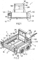
- a trailer 1 which can be pulled over a equipped with a trailer hitch 49 from a vehicle, in particular a motor vehicle of any kind, provided on the sides of the trailer 1 pairs of wheels 40, 41 and 42, 43 for locomotion are partially covered by Kotbleche 50, 51.
- the pairs of wheels 40, 41 and 42, 43 are attached to a trailer frame 210, 211, 289 (FIG. Figure 14 ) arranged.
- FIG 15 the front part 289 of the trailer frame is shown, which connects the two frame longitudinal members 210, 211 with the profile guides 80, 81 mounted thereon in the front region of the trailer 1 according to the invention and provides the connection point with the drawbar 49.
- a Hubstaplervoropathy 3 is provided, which between a transport position ( Fig.1, 2 ), in which load is transportable, and a loading position ( 3, 4 ), in the load with the Hubstaplervoruze 3 can be raised and lowered, is displaced.
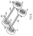
- two cross-connection elements 200, 201 (FIG. Figure 13 . 14 ), which connect the parallel frame longitudinal elements 210, 211 in the region of the wheels 40, 41, 42, 43, wherein the loading position of the Hubstaplervorplatz 3 - seen in the direction of travel - is located directly behind the rear of the two cross-connection elements 200, 201, so that the Hubstaplervortechnisch 3 is lowerable to the ground level 35 on which the trailer 1 is ( Figure 7 ).
- the two cross-connection elements 200, 201 are firmly screwed to the frame longitudinal elements 210, 211 to the stability of the frame to ensure.
- Number and type of wheels and the cross-connection elements may vary within the scope of the invention, in particular, in addition to the variant shown in the figures with two cross-connection elements 200, 201 and a trailer with only one cross-connection element or with more than two cross-connection elements realized. Accordingly, the trailer according to the invention may preferably be formed two-, four- or six-wheeled, with respect to the number of wheels, there is no restriction.
- a continuous wheel axle is to be understood, which is firmly connected to the trailer frame.
- the trailer 1 can also be pulled by hand and moved.
- Assisted is an extendable castor 60, which is supported on the drawbar 49.
- Equipment details such as suspension, size, shape and equipment of the trailer 1 are not specific to the invention and can be adapted to the requirements as desired.
- the Hubstaplervoretti 3 in transport position is essentially - seen in the direction of travel - in the front region of the trailer 1, as in Fig. 1, 2 shown.
- One of the Hubstaplervorides 3 deposited on the trailer 1, in the Fig.1, 2 not shown load is located above the continuous cross-connection elements 200, 201 and thus does not cause a tilting moment during the carriage.
- the transverse connecting elements 200, 201 passing through in the region of the wheels 40, 41, 42, 43 are, as already mentioned, firmly connected to the longitudinal frame elements 210, 211 ( Figure 13 ). Furthermore, the two cross-connection elements 200, 201 are formed in a manner known per se as hollow profiles ( Figure 11 ), in the ends of bearing legs 240, 241 for supporting the wheels 40, 41, 42, 43 are guided elastically rotatable. An impact force acting on the wheels 40, 41, 42, 43 is converted into a torsion of the elastic elements present in the hollow cross-connection elements 200, 201 and thus damps the impact effect.
- the trailer width does not exceed the usual extent in this construction.
- the cross-connection elements 200, 201 extend at a right angle to the longitudinal frame parts 210, 211, but they can be arranged obliquely.
- the inner structure or the profile of the cross-connection elements 200, 201 can be adapted to the respective needs and is not limited to any particular shape.
- FIG 13 there is shown a chassis usable for the purpose of the invention, which is known in this form and can be obtained from a manufacturer. Other embodiments of chassis are also applicable.
- Essential is the between opposite wheels 40, 41 and 42, 43 extending cross-connection of the frame longitudinal members 210, 211 through the parallel cross-connection elements 200, 201 to achieve a high frame stiffness and a small width of the trailer according to the invention.
- the bottom wall 72, 73 of the trailer 1 is at least partially removable in order to settle or receive the load moved by the Hubstäplervoriques 3 as close as possible to the rear cross-connection element 200 and thus to keep the tipping load as low as possible.
- the bottom wall of the trailer 1 is composed of a fixed, from Trailer frame held bottom wall portion 72 which extends from the front trailer area to the rear cross-connection element 200 and a removable bottom wall portion 73 (FIG. Figure 10 ), which extends from the rear cross-link 200 to the rear trailer wall 15.
- the removable bottom wall portion 73 may consist of one or more boards, which rest on the frame 210, 211 or on the cross-connection elements 200, 201 and can be removed if necessary or inserted into the trailer 1.
- the removable bottom wall part 73 is already removed from the trailer 1 and a rear trailer wall 15 (FIG. Fig.2 ), which may also be designed to be pivotable or tiltable, has been taken away in order to provide space for the lift-stacker device 3.
- the extent of the fixed and the removable bottom wall portion 72, 73 can be adapted to the requirements.
- the Hubstaplervorraum 3 is understood in the context of the invention, any type of lifting device with which a load can be raised or lowered.
- the Hubstaplervorraum 3 has a vertically movable stacker fork 2, which is formed of two parallel fork arms 20, 21, which can be introduced into corresponding fork slots of a load, not shown, to raise or lower this load.
- the distance between the fork arms 20, 21 adjustable, but can also be selected rigid.
- the fork arms 20, 21 of the forklift 2 are oriented opposite to the direction of travel of the trailer 1, so that the free ends of the fork arms 20, 21 point in the direction of the back of the trailer 1.
- An actuation of the Hubstaplervortechnik 3 is done by means of a hydraulic piston 291, but it can also be driven by a spindle or in another known to those skilled in the art.
- Fig.1 the hydraulic piston 291 is shown in its extended position, which corresponds to the raised position of the Hubstaplervor substances 3.
- the Hubstaplervoretti can also be designed so that it can be raised beyond the level shown.
- the mobility between the transport position and the loading position is achieved in that the Hubstaplervoropathy 3 is arranged on a horizontally movable horizontal slide 100, which laterally mounted guide rollers 101, 102 which in horizontally extending profile guides 80, 81, preferably U-profiles, the - as in Figure 14 shown - in parallel position to the longitudinal frame members 210, 211 connected to these, in particular screwed.
- a hydraulic piston 250 which can be extended in the direction of the trailer longitudinal axis and is operatively connected to the horizontal slide 100 via a hydraulic unit accommodated in a trailer box 290, can move the horizontal slide 100 horizontally between the transport position and the loading position.
- a hydraulic unit accommodated in a trailer box 290 which is located in the front trailer area, an additional control and operating unit and a battery supply are housed weatherproof.
- the hydraulic piston 250 In the loading position of the trailer 1, the hydraulic piston 250 is fully extended ( Figure 12 ).
- a support frame 160 is mounted, which is composed of two parallel vertical guide rails 162, 163 and an upper cross member 161.
- the Hubstaplervor substances 3 is vertically movable by means of a connected thereto, via rollers, guided vertical slide 177.
- the vertical slide 177 can be moved up and down via the hydraulically actuated piston 291.
- the type of lift truck drive is given here only by way of example and can be designed differently, for example via a threaded spindle driven by a crank or by means of a cable-driven hand crank.
- the support frame 160 is on the sides with Truncated pyramidal support elements 158, 159 secured against tilting movements caused by loads.
- taillights or reflectors 18, 19 are further provided for reasons of road safety.
Abstract
Description
Die Erfindung betrifft einen zweiachsigen Anhänger für ein Kraftfahrzeug mit einem Anhänger-Rahmen, an dessen Rahmen-Längselementen zwei in Längsrichtung voneinander beabstandete Räderpaare angeordnet sind, und einer im Inneren des Anhängers angebrachten Hubstaplervorrichtung, welche Hubstaplervorrichtung innerhalb des Anhängers zwischen einer Transpotstellung, in der Ladegut transportierbar ist, und einer Verladestellung, in der Ladegut mit der Hubstaplervorrichtung heb- und senkbar ist, verschiebbar ist, wobei zumindest ein Querverbindungselement vorgesehen ist, das die Rahmen-Längselemente im Bereich der Räder miteinander verbindet, und daß die Verladestellung der Hubstaplervorrichtung - in Fahrtrichtung gesehen - sich unmittelbar hinter dem zumindest einen Querverbindungselement befindet, sodaß die Hubstaplervorrichtung bis zum Bodenniveau, auf dem der Anhänger steht, absenkbar ist.The invention relates to a two-axle trailer for a motor vehicle with a trailer frame, on the frame longitudinal elements two longitudinally spaced pairs of wheels are arranged, and a mounted inside the trailer Hubstaplervorrichtung which Hubstaplervorrichtung within the trailer between a transposition, in the load can be transported, and a loading position in the load with the Hubstaplervorrichtung is raised and lowered, is displaceable, wherein at least one cross-connecting element is provided which connects the frame longitudinal elements in the wheels, and that the loading position of the Hubstaplervorrichtung - in the direction of travel Seen - is located immediately behind the at least one cross-connecting element, so that the Hubstaplervorrichtung is lowered to the ground level on which the trailer is.
Auf Baustellen erfolgt die Zubringung von Baumaterial, Werkzeugen etc. üblicherweise durch Lastkraftwagen-Transporte, welche für den Bauunternehmer entsprechende Frachtkosten verursachen. Nicht immer können solche Transporte ökonomisch sinnvoll ausgeführt werden, da nur die Lieferung von großen Materialmengen wirtschaftlich ist, diese aber vor Ort z.B. gegen Diebstahl oder Wettereinflüsse nicht ausreichend geschützt werden können. Dazu kommen die relativ langen Vorlaufzeiten für solche Transporte, da die Frächter für jede Bestellung eine Lieferzeit von mehreren Tagen benötigen.On construction sites, the delivery of building materials, tools, etc. usually takes place by truck transports, which cause corresponding freight costs for the contractor. Such transports can not always be carried out in an economically sensible way, since only the delivery of large quantities of material is economical, but they can be delivered on site, for example. can not be adequately protected against theft or weather. In addition, there are the relatively long lead times for such transports, since the shippers require a delivery time of several days for each order.
Kleinere Subunternehmer wiederum, die auf der Baustelle etwa nur für Bauarbeiten geringen Umfanges verantwortlich sind, benötigen oft nur relativ wenig Baumaterial, wie Sand, Fliesen, Zement od. dgl. und bringen diese in Klein-Transportern oder Anhängern mit, weil Lkw-Transporte hiefür zu hohe Kosten verursachen würden.Smaller subcontractors, on the other hand, who are only responsible for small-scale construction on the construction site, often only need relatively little building material, such as sand, tiles, cement or the like, and bring them with them in small transporters or trailers because of truck transports would cause too high a cost.
Insgesamt ist die Verbringung von kleinen Baumaterialmengen erwünscht und sinnvoll, bereitet aber einen entsprechenden Zeit- und Arbeitsaufwand, weil die Ladeflächen von Kleintransportern und Anhängern für ein rationelles Be- und Entladen nicht ausgelegt sind, und daher ein mühsames Manipulieren des Baumaterials bewerkstelligt werden muß. Was ein Llefer-Lkw mittels Kran in einem Arbeitsgang aufladen und entladen könnte, geschieht bei solchen kleineren Lieferungen z.B. durch Aufschultern und Tragen von Säcken oder anderen Behältnissen, da insbesondere kleine Baustellen über keine entsprechenden Kran- oder Hebevorrichtungen für diese Art von Arbeiten verfügen.Overall, the shipment of small amounts of building materials is desirable and useful, but prepares a corresponding time and effort, because the Loading surfaces of vans and trailers for a rational loading and unloading are not designed, and therefore a tedious manipulation of the building material must be accomplished. What a Llefer truck could load and unload by crane in a single operation is done in such smaller deliveries, for example, by shouldering and carrying sacks or other containers, since in particular small construction sites have no corresponding crane or lifting equipment for this type of work.
In der
Die
In der
In der
Aufgabe der Erfindung ist es daher, einen Anhänger der eingangs genannten Art anzugeben, mit dem Lasten geringen Umfanges so transportiert werden können, daß ein Beladen und Entladen des Anhängers mit geringem Arbeits- und Zeitaufwand möglich ist, der Anhänger aber eine ausreichende Stabilität bei geringem Eigengewicht aufweist.The object of the invention is therefore to provide a trailer of the type mentioned, with the loads of small extent can be transported so that a loading and unloading of the trailer with little effort and time is possible, the trailer but sufficient stability with low weight having.
Eine weitere Aufgabe der Erfindung besteht darin, einen Anhänger anzugeben, der mit einfachen technischen Mitteln realisierbar ist.Another object of the invention is to provide a trailer that can be realized by simple technical means.
Erfindungsgemäß wird dies dadurch erreicht, daß die Hubstaplervorrichtung entgegengesetzt zur Fahrrichtung des Anhängers orientierte Gabelarme umfaßt, die in entsprechende Gabelschlitze einer Last einbringbar sind, daß zwei mit den Rahmen-Längselementen fest verbundene Querverbindungselemente vorgesehen sind, die als Hohlprofile ausgebildet sind, in deren Enden Lagerschenkel zur Lagerung der Räder elastisch verdrehbar geführt sind, wobei die Hubstaplervorrichtung in der Verladestellung hinter dem hinteren Querverbindungselement der zwei Querverbindungselemente absenkbar ist.According to the invention this is achieved in that the Hubstaplervorrichtung opposite to the direction of travel of the trailer oriented fork arms, which are insertable into corresponding fork slots of a load that two fixedly connected to the frame longitudinal elements cross-connection elements are provided, which are formed as hollow profiles, in the ends of bearing legs are guided elastically rotatable for supporting the wheels, wherein the Hubstaplervorrichtung is lowered in the loading position behind the rear cross-connecting element of the two cross-connection elements.
Durch das Vorsehen von zwei Querverbindungselementen wird die für die Durchführung von Verladearbeiten mit der Hubstaplervorrichtung erforderliche Rahmensteifigkeit und zugleich eine leichte Bauweise des Anhängers erzielt, welche die Einsatzfähigkeit für verschiedenste Anwendungen verbessert und den Treibstoffverbrauch des Zugfahrzeuges erniedrigt. Zugleich wird die übliche Baubreite beim erfindungsgemäßen Anhänger nicht überschritten, wodurch zusätzliche Sicherheitsmaßnahmen und Schwierigkeiten mit der Typisierung wegfallen.The provision of two cross-linking elements, the necessary for the implementation of loading operations with the Hubstaplervorrichtung frame stiffness and at the same time a lightweight construction of the trailer is achieved, which improves the versatility for a variety of applications and reduces the fuel consumption of the towing vehicle. At the same time the usual width of the trailer according to the invention is not exceeded, eliminating additional security measures and difficulties with typing.
Die ale Hohlprofile ausgebildeten Querverbindungselemente stellen eine erhöhte Anhängerstabilität bereit und dienen zugleich der Radlagerung und Stoßdämpfung. Auf diese Weise kann eine sehr geringe Baubreite erzielt werden.The ale hollow profiles formed cross-connection elements provide increased trailer stability and also serve the wheel bearing and shock absorption. In this way, a very small width can be achieved.
Gemäß einer weiteren Ausführungsform der Erfindung kann der zur Verfügung stehende Raum im erfindungsgemäßen Anhänger dadurch vorteilhaft genutzt werden, daß die Hubstaplervorrichtung sich in Transportstellung im wesentlichen im vorderen Bereich des Anhängers und sich in Verladestellung im wesentlichen im Bereich des oder der Querverbindungselement(e) bzw. der Radachse(n) des Anhängers befindet, wobei die Hubstaplervorrichtung in Verladestellung hinter dem hinteren Querverbindungselement bzw. der hinteren Radachse bis zum Bodenniveau, auf dem der Anhänger steht, absenkbar ist.According to a further embodiment of the invention, the available standing space in the trailer according to the invention are advantageously used in that the Hubstaplervorrichtung is in transport position substantially in the front region of the trailer and in Verladestellung substantially in the region of the or the cross-connecting element (s) or the wheel axle (s) of the trailer, wherein the Hubstaplervorrichtung in Verladestellung behind the rear cross-member and the rear axle to the ground level on which the trailer is lowered.
Zu diesem Zweck kann in weiterer Ausbildung der Erfindung die Bodenwand des Anhängers zumindest teilweise entfernbar sein, sodaß die Hubstaplervorrichtung im Bereich des zumindest einen Querverbindungselements auf und ab bewegbar ist.For this purpose, in a further embodiment of the invention, the bottom wall of the trailer be at least partially removable, so that the Hubstaplervorrichtung in the region of the at least one cross-connecting element is movable up and down.
Insbesondere kann die Bodenwand sich aus einem fixen Bodenwandteil, der vom vorderen Anhängerbereich bis zu dem oder den Querverbindungselementen verläuft, und einem entfernbaren Bodenwandteil zusammensetzen, der sich von dem bzw. den Querverbindungselementen bis zur hinteren Anhängerwand erstreckt. Der auf diese Weise entfernbare Bodenwandteil kann bei Verladevorgängen aus dem erfindungsgemäßen Anhänger entnommen werden und dann die Hubstaplervorrichtung an den Übergang zwischen dem fixen Bodenwandelement und dem nunmehr offenen Bodenwandbereich herangeführt werden, um die Aufwärts- und Abwärtsbewegung des Hubstaplerelements durchführen zu können.In particular, the bottom wall may be composed of a fixed bottom wall portion extending from the front trailer portion to the cross member (s) and a removable bottom wall portion extending from the cross tie member (s) to the rear trailer wall. The removable in this way bottom wall part can be removed during loading operations from the trailer according to the invention and then the Hubstaplervorrichtung be brought to the transition between the fixed bottom wall element and the now open bottom wall portion to perform the upward and downward movement of the Hubstaplerelements can.
Eine Weiterbildung der Erfindung kann darin bestehen, daß die Hubstaplervorrichtung eine senkrecht verfahrbare Staplergabel, vorzugsweise mit zwei parallelen Gabelarmen aufweist. Mittels der Staplergabel können genormte Ladegutelemente, wie Paletten od. dgl. sowie Schüttgutvorrichtungen oder Betonmischmaschinen, welche geeignete Gabelschlitze aufweisen auf einfache Art und Weise auf den erfindungsgemäßen Anhänger geladen oder von diesem entladen werden. Der Abstand zwischen den Gabelarmen kann verstellbar sein, damit eine Anpassung auf unterschiedliche Ladevorrichtungen vorgenommen werden kann.A development of the invention may consist in that the Hubstaplervorrichtung has a vertically movable forklift fork, preferably with two parallel fork arms. Standardized load elements, such as pallets or the like, as well as bulk material devices or concrete mixers, which have suitable fork slots, can be loaded onto or unloaded from the trailer according to the invention in a simple manner by means of the forklift fork. The distance between the fork arms may be adjustable so that an adaptation to different charging devices can be made.
Um die Breite des Anhängers nicht zu groß zu dimensionieren, ist eine Ausrichtung der Gabelarme in Längsrichtung des Anhängers anzustreben. Für diesen Fall ist ein Be- und Entladen des Anhängers von der Rückseite des Anhängers aus bevorzugt, wobei die freien Enden der Gabelarme vorzugsweise entgegengesetzt zur Fahrtrichtung des Anhängers orientiert sind. Es können die Gabelarme entsprechend der jeweiligen Anforderungen auch anders angeordnet sein.In order not to dimension the width of the trailer too large, an alignment of the fork arms in the longitudinal direction of the trailer should be strived for. For this case, a loading and unloading of the trailer from the back of the trailer is preferred, with the free ends of the fork arms are preferably oriented opposite to the direction of travel of the trailer. It can be arranged differently according to the respective requirements, the fork arms.
Falls der Betrieb eines hydraulischen oder elektrischen Antriebs für die Hubstaplervorrichtung konstruktiv zu aufwendig ist, kann diese mit einer Handkurbel erfolgen, sodaß ein Abladen unabhängig vom Vorhandensein einer externen Energiequelle oder einer Kopplung mit dem Zug-Kraftwagen durchgeführt werden kann.If the operation of a hydraulic or electric drive for the Hubstaplervorrichtung is structurally too expensive, this can be done with a hand crank, so that a discharge can be performed regardless of the presence of an external power source or a coupling with the train cars.
Die Bewegbarkeit der Hubstaplervorrichtung des erfindungsgemäßen Anhängers kann auf verschiedene Arten geschehen, wobei gemäß einer Weiterbildung der Erfindung die Hubstaplervorrichtung auf einem horizontal verfahrbaren, hydraulisch angetriebenen Horizontal-Schlitten angeordnet ist, der zwischen der Transportstellung und der Verladestellung hin- und herbewegbar ist. Durch den Schlitten ist einerseits eine reibungsarme Bewegung möglich und andererseits bietet dieser eine stabile Auflage, um die während eines Verladevorganges wirksamen Kräfte und Kippmomente aufnehmen zu können.The mobility of the Hubstaplervorrichtung of the trailer according to the invention can be done in various ways, according to an embodiment of the invention, the Hubstaplervorrichtung is arranged on a horizontally movable, hydraulically driven horizontal carriage, which is reciprocated between the transport position and the loading position. By the slide on the one hand a low-friction movement is possible and on the other hand, this provides a stable support to absorb the forces and tilting moments effective during a loading process can.
Zum Zwecke einer leichtgängigen Verschiebbarkeit und einer sicheren Führung des horizontalen Schlittens innerhalb des erfindungsgemäßen Anhängers kann dieser seitlich angebrachte Führungsrollen aufweisen, die in waagrecht verlaufenden Profilführungen, die parallel zu den Seitenwänden des Anhängers angeordnet sind, geführt sind.For the purpose of smooth displacement and safe guidance of the horizontal carriage within the trailer according to the invention this may have laterally mounted guide rollers which are guided in horizontally extending profile guides, which are arranged parallel to the side walls of the trailer.
Die Profilführungen können beispielsweise durch U-Profile gebildet sein, die in Parallellage zu den Rahmen-Längselementen mit diesen verbunden sind und einen sicheren Halt der Führungsrollen des horizontal verfahrbaren Schlittens ermöglichen. Weiters kann auf dem horizontal verfahrbaren Schlitten ein Gestell mit vertikalen Führungsschienen angeordnet sein, in denen die Hubstaplervorrichtung, z.B. auf einem Vertikalschlitten senkrecht verfahrbar ist. In den Führungsschienen kann der Querschlitten z.B. über eine Rollenlagerung verschiebbar sein.The profile guides may for example be formed by U-profiles, which are connected in parallel to the frame longitudinal elements with these and allow a secure hold of the guide rollers of the horizontally movable carriage. Furthermore, a frame with vertical guide rails can be arranged on the horizontally movable carriage, in which the Hubstaplervorrichtung, eg vertically movable on a vertical slide. In the guide rails, the cross slide can be displaced, for example via a roller bearing.
So wie die Hubstaplervorrichtung kann auch der Horizontal-Schlitten in vielfacher Weise angetrieben werden, eine Ausführungsform der Erfindung kann darin bestehen, daß der horizontal verfahrbare Horizontal-Schlitten über eine entlang der Anhängerlängsachse verlaufende, mit dem Schlitten in Wirkverbindung stehende Gewindespindel verfahrbar ist, die über eine Spindel-Handkurbel antreibbar ist. Dadurch wird ein robuster und sicherer händischer Antrieb des Schlittens ohne Einsatz von Fremdenergie verwirklicht.As the Hubstaplervorrichtung also the horizontal slide can be driven in many ways, an embodiment of the invention may consist in that the horizontally movable horizontal slide on a along the trailer longitudinal axis extending, with the carriage in operative connection threaded spindle is movable over the a spindle hand crank is drivable. As a result, a robust and safe manual drive of the carriage is realized without the use of external energy.
Eine sichere und mechanisch stabile Festlegung der Anhänger-Seitenbegrenzung kann dadurch erreicht werden, daß auf den Rahmen-Längselementen Seitenwände befestigt sind.A secure and mechanically stable determination of the trailer side boundary can be achieved that are mounted on the frame longitudinal elements side walls.
Nachfolgend wird die Erfindung anhand eines in den angeschlossenen Zeichnungen dargestellten Ausführungsbeispiels der Erfindung eingehend erläutert. Es zeigt dabei
-
Fig.1 eine Rückansicht einer Ausführungsform des erfindungsgemäßen Anhängers mit der Hubstaplervorrichtung in Transportstellung; -
Fig.2 eine Schrägrißdarstellung des Anhängers gemäßFig.1 in Transportstellung; -
Fig.3 eine Rückansicht des Anhängers gemäßFig.1 in Verladestellung; -
Fig.4 eine Schrägrißdarstellung des Anhängers gemäßFig.1 in Verladestellung; -
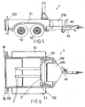
Fig 5 eine Seitenansicht des Anhängers gemäßFig.1 in Transportstellung; -
Fig.6 eine Draufsicht des Anhängers gemäßFig.1 in Transportstellung; -
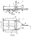
Fig.7 eine Seitenansicht des Anhängers gemäßFig.1 in Verladestellung; -
Fig.8 eine Draufsicht des Anhängers gemäßFig.1 in Verladestellung; -
Fig.9 einen Längsschnitt BB durch den Anhänger gemäßFig.1 in Verladestellung; -
Fig.10 eine Draufsicht des Anhängers gemäßFig.1 in Verladestellung; -
Fig.11 einen Längsschnitt BB durch den Anhänger gemäßFig.1 in Verladestellung; -
Fig.12 eine Draufsicht des Anhängers gemäßFig.1 in Verladestellung; -
Fig.13 einen Schrägriß des Fahrgestells des Anhängers gemäßFig.1 ; -
Fig.14 einen Schrägriß des Fahrgestells des Anhängers gemäßFig.1 mit montierten Laufschienen und Deichsel und -
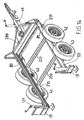
Fig.15 eine Explosionsdarstellung des Fahrgestells nachFig.14 ohne Deichsel.
-
Fig.1 a rear view of an embodiment of the trailer according to the invention with the Hubstaplervorrichtung in transport position; -
Fig.2 a Schräißißdarstellung the trailer according toFig.1 in transport position; -
Figure 3 a rear view of the trailer according toFig.1 in loading position; -
Figure 4 a Schräißißdarstellung the trailer according toFig.1 in loading position; -
Fig. 5 a side view of the trailer according toFig.1 in transport position; -
Figure 6 a plan view of the trailer according toFig.1 in transport position; -
Figure 7 a side view of the trailer according toFig.1 in loading position; -
Figure 8 a plan view of the trailer according toFig.1 in loading position; -
Figure 9 a longitudinal section BB through the trailer according toFig.1 in loading position; -
Figure 10 a plan view of the trailer according toFig.1 in loading position; -
Figure 11 a longitudinal section BB through the trailer according toFig.1 in loading position; -
Figure 12 a plan view of the trailer according toFig.1 in loading position; -
Figure 13 a Schrägriß the chassis of the trailer according toFig.1 ; -
Figure 14 a Schrägriß the chassis of the trailer according toFig.1 with mounted rails and drawbar and -
Figure 15 an exploded view of the chassis afterFigure 14 without drawbar.
In
In
Im Inneren des Anhängers 1 ist eine Hubstaplervorrichtung 3 vorgesehen, die zwischen einer Transportstellung (
Erfindungsgemäß sind zwei Querverbindungselemente 200, 201 (
Anzahl und Art der Räder und der Querverbindungselemente können im Rahmen der Erfindung variieren, insbesondere ist neben der in den Figuren dargestellten Variante mit zwei Querverbindungselementen 200, 201 auch ein Anhänger mit nur einem Querverbindungselement oder mit mehr als zwei Querverbindungselementen realisierbar. Entsprechend kann der erfindungsgemäße Anhänger vorzugsweise zwei-, vier- oder sechsrädrig ausgebildet sein, hinsichtlich der Anzahl der Räder besteht keine Einschränkung.Number and type of wheels and the cross-connection elements may vary within the scope of the invention, in particular, in addition to the variant shown in the figures with two
Als Querverbindungselement im Sinne der Erfindung ist auch eine durchgehende Radachse zu verstehen, die fest mit dem Anhängerrahmen verbunden ist.As a cross-connection element within the meaning of the invention, a continuous wheel axle is to be understood, which is firmly connected to the trailer frame.
Der Anhänger 1 kann auch mit der Hand gezogen und verschoben werden. Behilflich ist dabei eine ausfahrbare Lenkrolle 60, welche an der Deichsel 49 abgestützt ist. Ausstattungsdetails wie Radaufhängung, Größe, Form und Ausstattung des Anhängers 1 sind nicht erfindungsspezifisch und können den Erfordernissen beliebig angepasst sein.The
Dabei befindet sich die Hubstaplervorrichtung 3 in Transportstellung im wesentlichen - in Fahrtrichtung gesehen - im vorderen Bereich des Anhängers 1, wie in
In der in
Die im Bereich der Räder 40, 41, 42, 43 durchgehenden Querverbindungselemente 200, 201 sind, wie bereits erwähnt, mit den Rahmen-Längselementen 210, 211 fest verbunden sind (
Der innere Aufbau oder das Profil der Querverbindungselemente 200, 201 kann den jeweiligen Bedürfnissen angepasst sein und ist auf keine bestimmte Form beschränkt.The inner structure or the profile of the
In
Im gezeigten Ausführungsbeispiel ist die Bodenwand 72, 73 des Anhängers 1 zumindest teilweise entfernbar, um das von der Hubstäplervorrichtung 3 bewegte Ladegut möglichst nahe dem hinteren Querverbindungselement 200 absetzen oder aufnehmen zu können und damit die Kippbelastung möglichst gering zu halten.In the exemplary embodiment shown, the
Zu diesem Zweck setzt sich die Bodenwand des Anhängers 1 aus einem fixen, vom Anhängerrahmen gehaltenen Bodenwandteil 72, der vom vorderen Anhängerbereich bis zum hinteren Querverbindungselement 200 verläuft und einem entfernbaren Bodenwandteil 73 (
Der entfernbare Bodenwandteil 73 kann aus einem oder mehreren Brettern bestehen, die auf dem Rahmen 210, 211 oder auf den Querverbindungselementen 200, 201 aufliegen und bei Bedarf herausgenommen oder in den Anhänger 1 eingesetzt werden können. In
Unter der Hubstaplervorrichtung 3 wird im Rahmen der Erfindung jede Art von Hebevorrichtung verstanden, mit der eine Last angehoben oder abgesenkt werden kann. Im gezeigten Ausführungsbeispiel weist die Hubstaplervorrichtung 3 eine senkrecht verfahrbare Staplergabel 2 auf, die aus zwei parallelen Gabelarmen 20, 21 gebildet ist, die in entsprechende Gabelschlitze einer nicht dargestellten Last eingebracht werden können, um diese Last anzuheben oder abzusenken. Um vielfältige Anwendungsmöglichkeiten zuzulassen, ist der Abstand zwischen den Gabelarmen 20, 21 verstellbar, kann aber auch starr gewählt sein.Under the
Die Gabelarme 20, 21 der Staplergabel 2 sind entgegengesetzt zur Fahrtrichtung des Anhängers 1 orientiert, sodaß die freien Enden der Gabelarme 20, 21 in Richtung zur Rückseite des Anhängers 1 weisen. Eine Betätigung der Hubstaplervorrichtung 3 geschieht mit Hilfe eines Hydraulikkolbens 291, sie kann aber auch über eine Spindel oder in einer anderen dem Fachmann bekannten Art angetrieben sein. In
Da der Hub der Hubstaplervorrichtung 3 - in Gebrauchslage gesehen - bis zum Bodenniveau 35 (
Die Verfahrbarkeit zwischen der Transportstellung und der Verladestellung wird dadurch erreicht, daß die Hubstaplervorrichtung 3 auf einem horizontal verfahrbaren Horizontal-Schlitten 100 angeordnet ist, welcher seitlich angebrachte Führungsrollen 101, 102 aufweist, die in waagrecht verlaufenden Profilführungen 80, 81, vorzugsweise U-Profile, die - wie in
Über einen in Richtung der Anhängerlängsachse ausfahrbaren, mit dem Horizontal-Schlitten 100 in Wirkverbindung stehenden und über eine, in einem Anhängerkasten 290 untergebrachte Hydraulik-Einheit betätigbaren Hydraulikkolben 250 ist der Horizontal-Schlitten 100 horizontal zwischen der Transportstellung und der Verladestellung verfahrbar. Im Anhängerkasten 290, der sich im vorderen Anhängerbereich befindet, sind zusätzlich noch eine Steuerungs- und Bedieneinheit sowie eine Batterieversorgung wettergeschützt untergebracht. In der Verladestellung des Anhängers 1 ist der Hydraulikkolben 250 voll ausgefahren (
Auf dem Horizontal-Schlitten 100 ist ein Stützgestell 160 angebracht, das sich aus zwei parallelen Vertikal-Führungsschienen 162, 163 und einem oberen Querträger 161 zusammensetzt. In den zwei Vertikal-Führungsschienen 162, 163 ist die Hubstaplervorrichtung 3 mittels eines mit dieser verbundenen, über Rollen, geführten Vertikalschlittens 177 senkrecht verfahrbar. Der Vertikalschlitten 177 ist über den hydraulisch betätigten Kolben 291 auf- und abbewegbar. Die Art des Hubstapler-Antriebs ist hier nur beispielhaft angegeben und kann beliebig anders, z.B. über eine durch Kurbel angetriebene Gewindespindel oder mittels seilzuggetriebener Handkurbel ausgeführt sein. Das Stützgestell 160 ist an den Seiten mit pyramidenstumpfartigen Stützelementen 158, 159 gegen durch Lasten verursachte Kippbewegungen gesichert.On the
Soll der Anhänger 1, wie er in
Nun wird durch Verschiebung des Horizontal-Schlittens 100 infolge der Betätigung der Hydraulikkolbens 250 die Hubstaplervorrichtung 3 wieder in die Transportstellung gebracht und die Gabelarme 20, 21 mit ihrer Last wieder in Richtung Bodenwand 72 abgesenkt, sodaß die Last mit ihrer Unterseite auf der Bodenwand 72 zu liegen kommt und das Ladegut während des Transports sicher auf dieser ruht. Danach wird das entfernbare Bodenelement 73 wieder in den Anhänger 1 eingesetzt und die hintere Wand 15 wieder geschlossen.Now, by displacement of the
Unter Last oder Ladegut wird im Sinne der Erfindung alles von einem Anhänger transportierbare Gut oder Einrichtungen verstanden. Als Ladegutelement zum Bewegen der Last dienen einfache Paletten od. dgl., es kommen aber auch jegliche andere Vorrichtungen bzw. Werkzeuge oder Maschinen zum Transport bzw. Anheben und Absenken durch den erfindungsgemäßen Anhänger in Frage, welche mit Gabelarmen einer Hubstaplervorrichtung angehoben oder abgesenkt werden können. Hier besteht ein reichhaltiges Angebot an Zubehör, z.B. können mit den Gabelarmen 20, 21 ein an sich bekannter Kippbehälter für Schüttgut, eine an sich bekannte Arbeitsbühne, eine an sich bekannte Betonmaschine usw. gehoben und gesenkt sowie vom Anhänger 1 transportiert werden. Wie weit die vom erfindungsgemäßen Anhänger beförderte Last angehoben werden kann, wenn nicht nur das Transportieren und Ablegen von Lasten sondern auch ein darüber hinausgehendes Anheben ausgeführt werden soll, hängt von der jeweiligen Konstruktion der Hubstaplervorrichtung 3 ab und ist im Rahmen der Erfindung an die jeweiligen Erfordernisse anpaßbar.Under load or load is understood in the context of the invention, all transportable by a trailer Good or facilities. As loader element for moving the load are simple pallets od. Like., But there are also any other devices or tools or machinery for transport or lifting and lowering by the trailer according to the invention in question, which can be raised or lowered with fork arms of a Hubstaplervorrichtung , Here is a wide range of accessories, eg can with the fork arms 20, 21 a known dump tank for bulk material, a known working platform, a known concrete machine, etc. are raised and lowered and transported by the
Im hinteren Bereich des Anhängers 1 sind weiters aus Gründen der Verkehrssicherheit Rückleuchten bzw. Rückstrahler 18, 19 vorgesehen.In the rear area of the
Claims (4)
- Trailer (1) with two axes for a motor vehicle comprising a trailer frame (210, 211, 289) having two pairs of wheels (40, 41, 42, 43) arranged on the longitudinal elements (210, 211) thereof and located in longitudinal direction at a distance from each other and a forklift device (3) attached in the interior of the trailer (1), which forklift device (3) can be displaced inside the trailer (1) between a transport position in which goods can be transported and a loading position in which goods can be raised or lowered with the forklift device (3), there is provided at least one transverse connecting element (200, 201) which connects the frame longitudinal elements (210, 211) together in the area of the wheels (40, 41, 42, 43) and that the loading position of the forklift device (3), when viewed in the direction of travel, is located immediately behind the at least one transverse connecting element (200, 201) so that the forklift device (3) can be lowered as far as the ground level (35) on which the trailer (1) stands, characterised in that the forklift device comprises fork arms (20, 21) which are orientated opposite to the direction of travel of the trailer (1) and can be introduced into corresponding fork slits of a load, that two transverse connecting elements (200, 201) are provided, fixed to the longitudinal elements (210, 211) of the frame and being configured as hollow profiles, in the ends thereo bearing journals (240, 241) are guided in an elastically twistable manner for mounting the wheels (40, 41, 42, 43), in the loading position the forklift device (3) can be lowered behind the last transverse connecting element (200) of the two transverse connecting elements (200, 201).
- Trailer according to claim 1, characterised in that a load put down on the trailer (1) by the forklift device (3) is located above the two transverse connecting elements (200, 201).
- Trailer according to claim 1 or 2, characterised in that in the transport position, the forklift device (3) is located, when viewed in the direction of travel, substantially in the front area of the trailer (1).
- Trailer according to claim 1, 2 or 3, characterised in that a floor wall (72, 73) is provided which this is at least partly removable.
Priority Applications (2)
| Application Number | Priority Date | Filing Date | Title |
|---|---|---|---|
| SI200530559T SI1907310T1 (en) | 2005-05-20 | 2005-05-20 | Trailer for a motor vehicle |
| PL05740666T PL1907310T3 (en) | 2005-05-20 | 2005-05-20 | Trailer for a motor vehicle |
Applications Claiming Priority (1)
| Application Number | Priority Date | Filing Date | Title |
|---|---|---|---|
| PCT/AT2005/000173 WO2006122336A1 (en) | 2005-05-20 | 2005-05-20 | Trailer for a motor vehicle |
Publications (2)
| Publication Number | Publication Date |
|---|---|
| EP1907310A1 EP1907310A1 (en) | 2008-04-09 |
| EP1907310B1 true EP1907310B1 (en) | 2008-10-29 |
Family
ID=35107001
Family Applications (1)
| Application Number | Title | Priority Date | Filing Date |
|---|---|---|---|
| EP05740666A Active EP1907310B1 (en) | 2005-05-20 | 2005-05-20 | Trailer for a motor vehicle |
Country Status (7)
| Country | Link |
|---|---|
| EP (1) | EP1907310B1 (en) |
| CN (1) | CN101208253B (en) |
| AT (1) | ATE412607T1 (en) |
| BR (1) | BRPI0520261A2 (en) |
| DE (1) | DE502005005841D1 (en) |
| PL (1) | PL1907310T3 (en) |
| WO (1) | WO2006122336A1 (en) |
Families Citing this family (9)
| Publication number | Priority date | Publication date | Assignee | Title |
|---|---|---|---|---|
| DE102009023393A1 (en) * | 2009-05-29 | 2010-12-02 | Airbus Deutschland Gmbh | Transport device for use in mounting interior component modules in an aircraft |
| RU2624766C1 (en) * | 2016-02-29 | 2017-07-06 | Федеральное государственное бюджетное образовательное учреждение высшего профессионального образования "Пензенский государственный университет" (ФГБОУ ВПО "Пензенский государственный университет") | Trailer for vehicles |
| CH712469B1 (en) | 2016-05-17 | 2019-06-14 | Hanniske Kurt | Loading device for loading or unloading a load in and out of a transport vehicle and for transporting a load. |
| AT518649B1 (en) * | 2016-07-29 | 2017-12-15 | Bulmor Holding Gmbh | Self-propelled material handling equipment |
| US11427043B2 (en) * | 2016-08-09 | 2022-08-30 | Fahad ALRAJHI | Trailer for lifting and transporting loads |
| NO343459B1 (en) * | 2017-06-30 | 2019-03-18 | Multicargo As | Multipurpose trailer |
| CN108639033B (en) * | 2018-05-28 | 2024-04-09 | 徐工集团工程机械股份有限公司科技分公司 | Hand brake system and method for loader with trailer |
| AT523849B1 (en) | 2021-03-26 | 2021-12-15 | Varch Wolfgang | trailer for a motor vehicle |
| AT17376U1 (en) * | 2021-03-30 | 2022-02-15 | Varch Wolfgang | trailer for a motor vehicle |
Family Cites Families (5)
| Publication number | Priority date | Publication date | Assignee | Title |
|---|---|---|---|---|
| IE831782L (en) * | 1984-01-28 | 1985-07-28 | Thomas Davies | Trailor with fork-lift loading facility |
| DE8805335U1 (en) * | 1988-04-22 | 1988-06-23 | Willing, Hubert | |
| FR2654047A1 (en) * | 1989-11-08 | 1991-05-10 | Morel Michel | Road-going trailer equipped with a device making it possible to take, lift, transport, deposit a load from, on or onto a support |
| CN2117307U (en) * | 1992-03-12 | 1992-09-30 | 李青春 | Trailor of fork lifter |
| WO1995032917A1 (en) * | 1994-05-31 | 1995-12-07 | Pallet Boss Pty. Ltd. | Load transport vehicles |
-
2005
- 2005-05-20 AT AT05740666T patent/ATE412607T1/en active
- 2005-05-20 PL PL05740666T patent/PL1907310T3/en unknown
- 2005-05-20 CN CN2005800502420A patent/CN101208253B/en not_active Expired - Fee Related
- 2005-05-20 EP EP05740666A patent/EP1907310B1/en active Active
- 2005-05-20 WO PCT/AT2005/000173 patent/WO2006122336A1/en active Application Filing
- 2005-05-20 DE DE502005005841T patent/DE502005005841D1/en active Active
- 2005-05-20 BR BRPI0520261-2A patent/BRPI0520261A2/en not_active IP Right Cessation
Also Published As
| Publication number | Publication date |
|---|---|
| BRPI0520261A2 (en) | 2009-04-28 |
| ATE412607T1 (en) | 2008-11-15 |
| EP1907310A1 (en) | 2008-04-09 |
| WO2006122336A1 (en) | 2006-11-23 |
| CN101208253B (en) | 2010-05-12 |
| DE502005005841D1 (en) | 2008-12-11 |
| PL1907310T3 (en) | 2009-04-30 |
| CN101208253A (en) | 2008-06-25 |
Similar Documents
| Publication | Publication Date | Title |
|---|---|---|
| EP1907310B1 (en) | Trailer for a motor vehicle | |
| EP2443005B1 (en) | Transport system | |
| EP2260818B1 (en) | Load lift | |
| EP2079607A1 (en) | Floor-bound transportation vehicle, in particular for the transportation of containers | |
| DE4335456C2 (en) | Trucks for the transportation of goods | |
| EP0733003B1 (en) | Vehicle with superstructure | |
| DE19512246C2 (en) | Self-propelled loading system for containers or swap bodies that can be loaded and unloaded on a transport vehicle | |
| DE3213421C2 (en) | ||
| WO1986002326A1 (en) | Single-axle trailer | |
| EP0850157B1 (en) | Process and device for transporting light goods | |
| DE2648251A1 (en) | TRUCK WITH A LIFTING DEVICE | |
| AT523849B1 (en) | trailer for a motor vehicle | |
| DE1277038B (en) | Vehicle for the transport of large individual loads | |
| DE10019832A1 (en) | Auxiliary frame for safe adjustment and positioning of exchangeable container for lorry | |
| EP0883513B1 (en) | Quick-change attachment, means and use thereof for the transportation of lightweight goods | |
| DE10043398A1 (en) | Method of loading vehicles | |
| EP0901427B1 (en) | Loading space of a motor vehicle | |
| DE202007010664U1 (en) | Device for turning trolleys | |
| EP3604072B1 (en) | Liftable carrying device | |
| WO2006012652A1 (en) | Trailer for a motor vehicle | |
| WO2006047796A1 (en) | Trailer for a motor vehicle | |
| WO2016042147A1 (en) | Truck with a lifting device for containers | |
| EP1541501A1 (en) | transport unit | |
| WO2006039728A1 (en) | Transport container for goods | |
| DE10250852A1 (en) | Lorry-mounted skip loader and unloader includes both longitudinal- and vertical displacers |
Legal Events
| Date | Code | Title | Description |
|---|---|---|---|
| PUAI | Public reference made under article 153(3) epc to a published international application that has entered the european phase |
Free format text: ORIGINAL CODE: 0009012 |
|
| 17P | Request for examination filed |
Effective date: 20071214 |
|
| AK | Designated contracting states |
Kind code of ref document: A1 Designated state(s): AT BE BG CH CY CZ DE DK EE ES FI FR GB GR HU IE IS IT LI LT LU MC NL PL PT RO SE SI SK TR |
|
| AX | Request for extension of the european patent |
Extension state: AL BA HR LV MK YU |
|
| GRAP | Despatch of communication of intention to grant a patent |
Free format text: ORIGINAL CODE: EPIDOSNIGR1 |
|
| GRAS | Grant fee paid |
Free format text: ORIGINAL CODE: EPIDOSNIGR3 |
|
| GRAA | (expected) grant |
Free format text: ORIGINAL CODE: 0009210 |
|
| AK | Designated contracting states |
Kind code of ref document: B1 Designated state(s): AT BE BG CH CY CZ DE DK EE ES FI FR GB GR HU IE IS IT LI LT LU MC NL PL PT RO SE SI SK TR |
|
| AX | Request for extension of the european patent |
Extension state: AL BA HR LV MK YU |
|
| REG | Reference to a national code |
Ref country code: GB Ref legal event code: FG4D Free format text: NOT ENGLISH |
|
| REG | Reference to a national code |
Ref country code: CH Ref legal event code: EP |
|
| REG | Reference to a national code |
Ref country code: IE Ref legal event code: FG4D Free format text: LANGUAGE OF EP DOCUMENT: GERMAN |
|
| REF | Corresponds to: |
Ref document number: 502005005841 Country of ref document: DE Date of ref document: 20081211 Kind code of ref document: P |
|
| REG | Reference to a national code |
Ref country code: CH Ref legal event code: NV Representative=s name: RIEDERER HASLER & PARTNER PATENTANWAELTE AG |
|
| NLV1 | Nl: lapsed or annulled due to failure to fulfill the requirements of art. 29p and 29m of the patents act | ||
| LTIE | Lt: invalidation of european patent or patent extension |
Effective date: 20081029 |
|
| PG25 | Lapsed in a contracting state [announced via postgrant information from national office to epo] |
Ref country code: ES Free format text: LAPSE BECAUSE OF FAILURE TO SUBMIT A TRANSLATION OF THE DESCRIPTION OR TO PAY THE FEE WITHIN THE PRESCRIBED TIME-LIMIT Effective date: 20090209 Ref country code: LT Free format text: LAPSE BECAUSE OF FAILURE TO SUBMIT A TRANSLATION OF THE DESCRIPTION OR TO PAY THE FEE WITHIN THE PRESCRIBED TIME-LIMIT Effective date: 20081029 Ref country code: BG Free format text: LAPSE BECAUSE OF FAILURE TO SUBMIT A TRANSLATION OF THE DESCRIPTION OR TO PAY THE FEE WITHIN THE PRESCRIBED TIME-LIMIT Effective date: 20090129 |
|
| REG | Reference to a national code |
Ref country code: PL Ref legal event code: T3 |
|
| PG25 | Lapsed in a contracting state [announced via postgrant information from national office to epo] |
Ref country code: NL Free format text: LAPSE BECAUSE OF FAILURE TO SUBMIT A TRANSLATION OF THE DESCRIPTION OR TO PAY THE FEE WITHIN THE PRESCRIBED TIME-LIMIT Effective date: 20081029 Ref country code: IS Free format text: LAPSE BECAUSE OF FAILURE TO SUBMIT A TRANSLATION OF THE DESCRIPTION OR TO PAY THE FEE WITHIN THE PRESCRIBED TIME-LIMIT Effective date: 20090228 Ref country code: FI Free format text: LAPSE BECAUSE OF FAILURE TO SUBMIT A TRANSLATION OF THE DESCRIPTION OR TO PAY THE FEE WITHIN THE PRESCRIBED TIME-LIMIT Effective date: 20081029 Ref country code: PT Free format text: LAPSE BECAUSE OF FAILURE TO SUBMIT A TRANSLATION OF THE DESCRIPTION OR TO PAY THE FEE WITHIN THE PRESCRIBED TIME-LIMIT Effective date: 20090330 |
|
| REG | Reference to a national code |
Ref country code: IE Ref legal event code: FD4D |
|
| PG25 | Lapsed in a contracting state [announced via postgrant information from national office to epo] |
Ref country code: IE Free format text: LAPSE BECAUSE OF FAILURE TO SUBMIT A TRANSLATION OF THE DESCRIPTION OR TO PAY THE FEE WITHIN THE PRESCRIBED TIME-LIMIT Effective date: 20081029 Ref country code: DK Free format text: LAPSE BECAUSE OF FAILURE TO SUBMIT A TRANSLATION OF THE DESCRIPTION OR TO PAY THE FEE WITHIN THE PRESCRIBED TIME-LIMIT Effective date: 20081029 Ref country code: RO Free format text: LAPSE BECAUSE OF FAILURE TO SUBMIT A TRANSLATION OF THE DESCRIPTION OR TO PAY THE FEE WITHIN THE PRESCRIBED TIME-LIMIT Effective date: 20081029 Ref country code: EE Free format text: LAPSE BECAUSE OF FAILURE TO SUBMIT A TRANSLATION OF THE DESCRIPTION OR TO PAY THE FEE WITHIN THE PRESCRIBED TIME-LIMIT Effective date: 20081029 |
|
| PG25 | Lapsed in a contracting state [announced via postgrant information from national office to epo] |
Ref country code: SE Free format text: LAPSE BECAUSE OF FAILURE TO SUBMIT A TRANSLATION OF THE DESCRIPTION OR TO PAY THE FEE WITHIN THE PRESCRIBED TIME-LIMIT Effective date: 20090129 Ref country code: CZ Free format text: LAPSE BECAUSE OF FAILURE TO SUBMIT A TRANSLATION OF THE DESCRIPTION OR TO PAY THE FEE WITHIN THE PRESCRIBED TIME-LIMIT Effective date: 20081029 |
|
| PLBE | No opposition filed within time limit |
Free format text: ORIGINAL CODE: 0009261 |
|
| STAA | Information on the status of an ep patent application or granted ep patent |
Free format text: STATUS: NO OPPOSITION FILED WITHIN TIME LIMIT |
|
| PG25 | Lapsed in a contracting state [announced via postgrant information from national office to epo] |
Ref country code: SK Free format text: LAPSE BECAUSE OF FAILURE TO SUBMIT A TRANSLATION OF THE DESCRIPTION OR TO PAY THE FEE WITHIN THE PRESCRIBED TIME-LIMIT Effective date: 20081029 |
|
| 26N | No opposition filed |
Effective date: 20090730 |
|
| BERE | Be: lapsed |
Owner name: VARCH, WOLFGANG Effective date: 20090531 |
|
| PG25 | Lapsed in a contracting state [announced via postgrant information from national office to epo] |
Ref country code: MC Free format text: LAPSE BECAUSE OF NON-PAYMENT OF DUE FEES Effective date: 20090531 |
|
| PG25 | Lapsed in a contracting state [announced via postgrant information from national office to epo] |
Ref country code: BE Free format text: LAPSE BECAUSE OF NON-PAYMENT OF DUE FEES Effective date: 20090531 |
|
| PG25 | Lapsed in a contracting state [announced via postgrant information from national office to epo] |
Ref country code: GR Free format text: LAPSE BECAUSE OF FAILURE TO SUBMIT A TRANSLATION OF THE DESCRIPTION OR TO PAY THE FEE WITHIN THE PRESCRIBED TIME-LIMIT Effective date: 20090130 |
|
| PG25 | Lapsed in a contracting state [announced via postgrant information from national office to epo] |
Ref country code: IT Free format text: LAPSE BECAUSE OF NON-PAYMENT OF DUE FEES Effective date: 20100520 |
|
| PG25 | Lapsed in a contracting state [announced via postgrant information from national office to epo] |
Ref country code: LU Free format text: LAPSE BECAUSE OF NON-PAYMENT OF DUE FEES Effective date: 20090520 |
|
| PG25 | Lapsed in a contracting state [announced via postgrant information from national office to epo] |
Ref country code: HU Free format text: LAPSE BECAUSE OF FAILURE TO SUBMIT A TRANSLATION OF THE DESCRIPTION OR TO PAY THE FEE WITHIN THE PRESCRIBED TIME-LIMIT Effective date: 20090430 |
|
| PGRI | Patent reinstated in contracting state [announced from national office to epo] |
Ref country code: IT Effective date: 20110616 |
|
| PG25 | Lapsed in a contracting state [announced via postgrant information from national office to epo] |
Ref country code: TR Free format text: LAPSE BECAUSE OF FAILURE TO SUBMIT A TRANSLATION OF THE DESCRIPTION OR TO PAY THE FEE WITHIN THE PRESCRIBED TIME-LIMIT Effective date: 20081029 |
|
| PG25 | Lapsed in a contracting state [announced via postgrant information from national office to epo] |
Ref country code: CY Free format text: LAPSE BECAUSE OF FAILURE TO SUBMIT A TRANSLATION OF THE DESCRIPTION OR TO PAY THE FEE WITHIN THE PRESCRIBED TIME-LIMIT Effective date: 20081029 |
|
| REG | Reference to a national code |
Ref country code: DE Ref legal event code: R082 Ref document number: 502005005841 Country of ref document: DE Representative=s name: PATENT- UND RECHTSANWAELTE MEINKE, DABRINGHAUS, DE |
|
| REG | Reference to a national code |
Ref country code: DE Ref legal event code: R082 Ref document number: 502005005841 Country of ref document: DE Representative=s name: PATENT- UND RECHTSANWAELTE MEINKE, DABRINGHAUS, DE Effective date: 20141218 Ref country code: DE Ref legal event code: R081 Ref document number: 502005005841 Country of ref document: DE Owner name: REAL-DYNAMIC-VERMOEGENSVERWALTUNGSGESELLSCHAFT, AT Free format text: FORMER OWNER: VARCH, WOLFGANG, PISCHELDORF, AT Effective date: 20141218 |
|
| REG | Reference to a national code |
Ref country code: CH Ref legal event code: PUE Owner name: REAL-DYNAMIC-VERMOEGENSVERWALTUNGSGESELLSCHAFT, AT Free format text: FORMER OWNER: VARCH, WOLFGANG, AT |
|
| REG | Reference to a national code |
Ref country code: GB Ref legal event code: 732E Free format text: REGISTERED BETWEEN 20150108 AND 20150114 |
|
| REG | Reference to a national code |
Ref country code: FR Ref legal event code: TP Owner name: REAL-DYNAMIC-VERMOGENSVERWALTUNGSGESELLSCHAFT , AT Effective date: 20150121 |
|
| REG | Reference to a national code |
Ref country code: SI Ref legal event code: SP73 Owner name: REAL-DYNAMIC; AT Effective date: 20150216 |
|
| REG | Reference to a national code |
Ref country code: AT Ref legal event code: PC Ref document number: 412607 Country of ref document: AT Kind code of ref document: T Owner name: REAL-DYNAMIC-VERMOEGENSVERWALTUNGSGESELLSCHAFT, AT Effective date: 20151109 |
|
| REG | Reference to a national code |
Ref country code: FR Ref legal event code: PLFP Year of fee payment: 12 |
|
| PGFP | Annual fee paid to national office [announced via postgrant information from national office to epo] |
Ref country code: CH Payment date: 20160525 Year of fee payment: 12 Ref country code: GB Payment date: 20160525 Year of fee payment: 12 |
|
| PGFP | Annual fee paid to national office [announced via postgrant information from national office to epo] |
Ref country code: FR Payment date: 20160504 Year of fee payment: 12 Ref country code: SI Payment date: 20160518 Year of fee payment: 12 Ref country code: PL Payment date: 20160519 Year of fee payment: 12 Ref country code: IT Payment date: 20160520 Year of fee payment: 12 |
|
| REG | Reference to a national code |
Ref country code: CH Ref legal event code: PL |
|
| GBPC | Gb: european patent ceased through non-payment of renewal fee |
Effective date: 20170520 |
|
| PG25 | Lapsed in a contracting state [announced via postgrant information from national office to epo] |
Ref country code: CH Free format text: LAPSE BECAUSE OF NON-PAYMENT OF DUE FEES Effective date: 20170531 Ref country code: LI Free format text: LAPSE BECAUSE OF NON-PAYMENT OF DUE FEES Effective date: 20170531 Ref country code: SI Free format text: LAPSE BECAUSE OF NON-PAYMENT OF DUE FEES Effective date: 20170521 |
|
| REG | Reference to a national code |
Ref country code: SI Ref legal event code: KO00 Effective date: 20180111 |
|
| REG | Reference to a national code |
Ref country code: FR Ref legal event code: ST Effective date: 20180131 |
|
| PG25 | Lapsed in a contracting state [announced via postgrant information from national office to epo] |
Ref country code: GB Free format text: LAPSE BECAUSE OF NON-PAYMENT OF DUE FEES Effective date: 20170520 |
|
| PG25 | Lapsed in a contracting state [announced via postgrant information from national office to epo] |
Ref country code: FR Free format text: LAPSE BECAUSE OF NON-PAYMENT OF DUE FEES Effective date: 20170531 Ref country code: IT Free format text: LAPSE BECAUSE OF NON-PAYMENT OF DUE FEES Effective date: 20170520 |
|
| PG25 | Lapsed in a contracting state [announced via postgrant information from national office to epo] |
Ref country code: PL Free format text: LAPSE BECAUSE OF NON-PAYMENT OF DUE FEES Effective date: 20170520 |
|
| P01 | Opt-out of the competence of the unified patent court (upc) registered |
Effective date: 20230519 |
|
| P02 | Opt-out of the competence of the unified patent court (upc) changed |
Effective date: 20230522 |
|
| PGFP | Annual fee paid to national office [announced via postgrant information from national office to epo] |
Ref country code: DE Payment date: 20230531 Year of fee payment: 19 |
|
| PGFP | Annual fee paid to national office [announced via postgrant information from national office to epo] |
Ref country code: AT Payment date: 20230524 Year of fee payment: 19 |