EP1902876B1 - Air distribution case, in particular for a vehicle air conditioner, having a distribution valve and method of controlling such a distribution valve - Google Patents
Air distribution case, in particular for a vehicle air conditioner, having a distribution valve and method of controlling such a distribution valve Download PDFInfo
- Publication number
- EP1902876B1 EP1902876B1 EP06291485A EP06291485A EP1902876B1 EP 1902876 B1 EP1902876 B1 EP 1902876B1 EP 06291485 A EP06291485 A EP 06291485A EP 06291485 A EP06291485 A EP 06291485A EP 1902876 B1 EP1902876 B1 EP 1902876B1
- Authority
- EP
- European Patent Office
- Prior art keywords
- air
- distribution
- distribution valve
- air duct
- defrosting
- Prior art date
- Legal status (The legal status is an assumption and is not a legal conclusion. Google has not performed a legal analysis and makes no representation as to the accuracy of the status listed.)
- Expired - Fee Related
Links
Images


Classifications
-
- B—PERFORMING OPERATIONS; TRANSPORTING
- B60—VEHICLES IN GENERAL
- B60H—ARRANGEMENTS OF HEATING, COOLING, VENTILATING OR OTHER AIR-TREATING DEVICES SPECIALLY ADAPTED FOR PASSENGER OR GOODS SPACES OF VEHICLES
- B60H1/00—Heating, cooling or ventilating [HVAC] devices
- B60H1/00642—Control systems or circuits; Control members or indication devices for heating, cooling or ventilating devices
- B60H1/00664—Construction or arrangement of damper doors
- B60H1/00671—Damper doors moved by rotation; Grilles
- B60H1/00678—Damper doors moved by rotation; Grilles the axis of rotation being in the door plane, e.g. butterfly doors
-
- B—PERFORMING OPERATIONS; TRANSPORTING
- B60—VEHICLES IN GENERAL
- B60H—ARRANGEMENTS OF HEATING, COOLING, VENTILATING OR OTHER AIR-TREATING DEVICES SPECIALLY ADAPTED FOR PASSENGER OR GOODS SPACES OF VEHICLES
- B60H1/00—Heating, cooling or ventilating [HVAC] devices
- B60H1/00007—Combined heating, ventilating, or cooling devices
- B60H1/00021—Air flow details of HVAC devices
- B60H1/00028—Constructional lay-out of the devices in the vehicle
-
- B—PERFORMING OPERATIONS; TRANSPORTING
- B60—VEHICLES IN GENERAL
- B60H—ARRANGEMENTS OF HEATING, COOLING, VENTILATING OR OTHER AIR-TREATING DEVICES SPECIALLY ADAPTED FOR PASSENGER OR GOODS SPACES OF VEHICLES
- B60H1/00—Heating, cooling or ventilating [HVAC] devices
- B60H1/00507—Details, e.g. mounting arrangements, desaeration devices
- B60H1/00514—Details of air conditioning housings
-
- B—PERFORMING OPERATIONS; TRANSPORTING
- B60—VEHICLES IN GENERAL
- B60H—ARRANGEMENTS OF HEATING, COOLING, VENTILATING OR OTHER AIR-TREATING DEVICES SPECIALLY ADAPTED FOR PASSENGER OR GOODS SPACES OF VEHICLES
- B60H1/00—Heating, cooling or ventilating [HVAC] devices
- B60H1/00642—Control systems or circuits; Control members or indication devices for heating, cooling or ventilating devices
- B60H1/00814—Control systems or circuits characterised by their output, for controlling particular components of the heating, cooling or ventilating installation
- B60H1/00821—Control systems or circuits characterised by their output, for controlling particular components of the heating, cooling or ventilating installation the components being ventilating, air admitting or air distributing devices
- B60H1/00835—Damper doors, e.g. position control
- B60H1/00842—Damper doors, e.g. position control the system comprising a plurality of damper doors; Air distribution between several outlets
-
- B—PERFORMING OPERATIONS; TRANSPORTING
- B60—VEHICLES IN GENERAL
- B60H—ARRANGEMENTS OF HEATING, COOLING, VENTILATING OR OTHER AIR-TREATING DEVICES SPECIALLY ADAPTED FOR PASSENGER OR GOODS SPACES OF VEHICLES
- B60H1/00—Heating, cooling or ventilating [HVAC] devices
- B60H1/00642—Control systems or circuits; Control members or indication devices for heating, cooling or ventilating devices
- B60H1/00664—Construction or arrangement of damper doors
- B60H2001/00721—Air deflecting or air directing means
Definitions
- the invention relates to an air duct housing, in particular for a motor vehicle air conditioning system.
- a vehicle air conditioning system comprising a housing and a heater core arranged substantially horizontally in the housing.
- the housing has a central headspace opening disposed in a side wall of the housing at substantially the same height as the heater core, a defrost opening, and a footwell outlet.
- a hot air duct is disposed above the heater core to conduct warm air passing through the heater core. Warm air guided by the hot air guide is mixed with cool air bypassing the heater core and flows toward the defrost opening through an air port formed through an end portion of the warm air guide.
- the opening area of the air connection is simply increased by the length of the hot air duct is increased without increasing the size of the vehicle air conditioner. As a result, a sufficient amount of air is introduced into the defrost opening.
- the EP 0447 304 B1 discloses a device for ventilating and heating a passenger compartment of a motor vehicle with a arranged in a housing, pivotable about a pivot axis distribution flap, which regulates the air distribution to at least two adjacent air outlets for distribution of fresh and hot air in different zones of the passenger compartment.
- the distributor flap in this case has a first part and a second part, which extend in each case on both sides of the pivot axis of the distributor flap, wherein the first flap part has at least two baffles which are axially and angularly displaced from each other to the air distribution through the outlets of the first line to selectively control, and wherein the second flap part includes a deflection element for controlling the air distribution at the outlet of the second conduit.
- the first line on two inner walls which forms three adjacent air outlets, namely a central outlet and two lateral outlets.
- the first part of the distribution flap includes three axially and angularly displaced deflection elements and two lateral deflection elements, which are suitable for controlling the central outlet or the two aforementioned lateral outlets, while the second part of the distributor flap a single Includes deflecting element, which is suitable for controlling the exit of the second line.
- the central outlet opens into a vent at the level of the instrument panel.
- the two side outlets open into defrost openings of the windshield, and the outlet of the second line opens into an opening in the lower part of the passenger compartment.
- GB 2 346 209 discloses as the closest prior art einluft outsgeophuse with a distribution flap for center, side and Defrostdüsen. Further, from the document FR 278 9017 a distributor flap for a central ventilation channel and two lateral channels to side nozzles known.
- a distribution flap is provided in an air duct housing, in particular for a motor vehicle air conditioner, with at least one distribution flap pivotally mounted in an air duct housing about a pivot axis regulating the air distribution to a plurality of air ducts emanating from the air duct housing, at least one of the air ducts for side defrosting and at least one of the air ducts for windscreen defrosting is used, and in each operating position of the distributor flap, in which warm air can be fed to the vehicle interior, the distributor flap leaves at least a minimum opening through the air ducts for side defrosting.
- the distributor flap opening to the air duct or channels for side defrosting is preferably designed such that at least in operating positions "warm” 5% to 10% of the total, regulated by the distributor flap air flow through the air ducts for side defrosting is directed. This amount of air ensures adequate defrosting of the side windows and does not affect the comfort in the vehicle interior.
- the distributor flap is a butterfly flap, wherein the wings are arranged at an angle of less than 180 °, in particular less than 120 ° to each other. Particularly preferably, a plurality of sections are provided in the pivot axis longitudinal direction of the distribution flap, in which the wings occupy different angles.
- the distributor flap has individual sections, wherein preferably the section which is assigned to the air duct for controlling the side defroster is arranged rotated by an angle with respect to the section which is assigned to the air duct for controlling the windscreen defroster. This angle is preferably 5 ° to 25 °, particularly preferably 10 ° to 20 °. Between each of these two twisted arranged portions is preferably provided extending approximately in the radial direction transition region, which prevents cross-currents of the air and increases the stability of the distribution flap.
- To increase the rigidity may be provided on the surfaces of the distribution valve stiffening ribs.
- the distribution flap has individual sections, wherein preferably the section which is assigned to the air duct to the side nozzle offset by an offset relative to the portion which is associated with the air duct to the center nozzle, in particular offset in parallel, is arranged.
- the offset is preferably 2 to 10 mm, particularly preferably 5 +/- 3 mm.
- the portion which is assigned to the air duct for controlling the side defroster, seen in the longitudinal direction of the distributor flap is formed shorter than the portion which is associated with the air duct to the side nozzle, and / or the portion associated with the air duct for controlling the windshield defroster is formed longer in the longitudinal direction of the distribution flap, as the portion which is associated with the air duct to the center nozzle.
- the total length of the sections associated with the defrost is equal to the total length of the sections associated with the center and side nozzles, but the total lengths may also differ.
- the distributor flap preferably provides forced ventilation through the side nozzle.
- This forced ventilation is preferably ensured by an offset of the flap surfaces of the distributor flap, which is assigned to the center and side nozzles, for which purpose the corresponding flap surface sections are arranged offset from one another.
- the surfaces are arranged parallel to one another.
- a motor vehicle air conditioning system 1 with an evaporator and heater (not shown) arranged in a plastic air-injection molded housing 2 (not shown) is used for air temperature control of the vehicle interior of a motor vehicle.
- a single-wing footwell flap 5 Adjacent to the substantially two-wing distributor flap 3, a single-wing footwell flap 5 is arranged, which regulates the air flow through an air channel F to the front foot space, being pivotable about a pivot axis which is arranged parallel to the pivot axis of the distributor flap 3.
- the wing of the footwell flap 5 pivots into the mixing chamber 4, while the corresponding wing of the distributor flap 3, which regulates the air flow to the center and side jets, pivots in the direction of the air channels MD and SD and protrudes into the mixing chamber 4 in any position.
- the second wing of the distributor flap 3, which is associated with the defrost opening, also pivots in the direction of the corresponding air channels ME and SE.
- Another air channel FF branches further down from the mixing chamber 4 and leads air to the rear area.
- the mixing chamber 4 is supplied directly from the evaporator coming cold air and / or coming from the heater hot air by means of one or more mixing flaps (not shown) adjustable and mixed in the same before the tempered air enters the individual air channels.
- the provision of usually by means of flaps or the like. controllable bypasses to the distributor flap and / or mixing flap, for example, to achieve a temperature stratification is possible in principle.
- a single-tone air conditioning system is provided, however, a corresponding embodiment may also be provided for a multi-zone air conditioning system, wherein in the case of a zone subdivision of driver and passenger side a central partition and a divided distribution flap is provided with separate control of the sides.
- the air guide housing 2 is formed differently in the areas indicated by the arrows X and Y in the figures, so that the opening to the air channel SE opens earlier than the opening to the air duct ME. This is effected by a further raised wall, which reduces the air passage to the distributor flap 3.
- a cross-sectional widening in the form of a curvature to the outside begins earlier in the air duct SE for the side defroster, ie earlier in relation to the swiveling angle of the distributor flap 3 than in the air duct ME for defrosting the windscreen. At an angle ⁇ (see Fig.
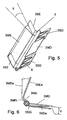
- the distributor flap 3 has three individual sections 3SE, 3SE and 3ME, in each case the outer axis 3SE associated with one of the air ducts SE for regulating the side defroster by an angle ⁇ with respect to the central section 3ME, which corresponds to the air duct ME assigned to control the windshield defrosting, is arranged twisted (see FIGS. 5 and 6 ).
- the angle ⁇ is preferably 5 ° to 25 °, in the present case about 20 °, so that each of the outer side defrosting sections 3SE of the distributor flap 3 releases the corresponding outlet opening to the air channel SE faster than the further middle and significantly larger section 3ME, which is assigned to the windscreen defrosting and thus the air channel SM.
- transition areas are arranged in the radial direction. These serve, inter alia, the stiffening of the distributor flap.
- a distribution flap position within the angle ⁇ is shown - in contrast to the middle, the windshield defroster associated area, ie the section 3ME - in the respective outer region of the distributor door 3, the cross section between the air duct housing 2 and distributor flap 3 already formed extended, which by the angular offset (angle ⁇ ) of the distributor door 3 yet is amplified, so that even at a low defrost position of the distributor flap 3, a relatively large air flow for the side defroster is available, while the windshield in the corresponding distributor flap position only a relatively small air flow is supplied.
- the portion 3ME has a slightly smaller radial extent than the two outer portions 3SE.
- the sections 3ME and 3SE have a first, in the radial direction with respect to the pivot axis extending inner region 3MEi and 3SEi, wherein the angular offset by the angle ⁇ is already provided in this area.
- sections 3SE and 3ME are angled at an angle of about 135 ° such that a substantial portion of sections 3ME and 3SE (exterior 3MEa and 3SEa), presently about four fifths of the total "radial" extent, do not extend in the radial direction with respect to the pivot axis (see Fig. 6 ).
- the outer axis portions 3SE in the swinging axis longitudinal direction each have a width of about one fifth of the width of the middle portion 3ME.
- the outermost region of the middle outer region 3MEa seen in the radial direction is also bent slightly curved, as in particular from Fig. 6 can be seen, whereby the flow path of the air is blocked over a slightly larger angular range (see Fig. 3 ).
- the distributor flap 3 also has three sections 3SD and 3MD for controlling the air supply of the side and center nozzles, which release the openings of the corresponding air channels SD and MD or completely or partially close.
- the middle portion 3MD extends in the radial direction with respect to the distributor flap pivot axis.
- the angle to the interior 3MEi is presently about 135 °.
- the lateral sections 3SD are - formed angled according to the sections 3SE and 3ME, wherein the respective inner area 3SDi extends approximately in extension of the inner areas 3SEi (see Fig. 6 ).
- the outside area 3SEa extends parallel to the middle section 3MD, resulting in an offset V of the sections.
- the offset V is usually between 2 and 10 mm, in this case 5 mm.
- ribs 6 are arranged on one flap surface each. How out Fig. 5 it can be seen, in each case two ribs 6 are arranged on the sections 3SD, which have a trapezoidal course, wherein the base is formed by the shaft region of the distributor flap 3. In the section 3MD on the ribs 6 of the sections 3SD facing flap surface a plurality, in the present case six, ribs 6 are arranged, which extend in the radial direction to the outside and have a triangular course of their height.
- the assembly of the distributor flap 3 in the air guide housing 2 is, as in the FIGS. 8 and 9 shown, easily possible if the air duct housing 2 is formed divided in the middle, and are inserted together with the distributor flap 3 in one of the halves, the halves and fixed together.
- Fig. 10 shows a section along by an air conditioner according to a variant of the embodiment described above, wherein the distributor flaps 3 and the releasable by the distributor flap 3 cross sections in the air guide housing 2 correspond to each other, so that the distributor flap 3 as well as their function is not described in detail.
- a mixing chamber 4 from which branches off a plurality of air channels.
- the regulation of the air distribution to the front area is done by means of said distributor flap 3 and a footwell flap 5, which regulates the inlet opening to the air channel F to the front footwell. How out Fig.
- the distributor flap 3 closes the air duct MD completely when the operating position 100% defrosting operation, as shown, is provided. In this operating position, moreover, the air channel F to the front footwell as well as the air duct FF to the rear area is closed, so that essentially all the air is available for defrosting the front and side windows.
- a small opening to the side nozzles is open due to the offset of the distributor flap 3, so that a (small) air flow flows to the side nozzles, which supports the defrosting of the side nozzles.
Landscapes
- Physics & Mathematics (AREA)
- Thermal Sciences (AREA)
- Engineering & Computer Science (AREA)
- Mechanical Engineering (AREA)
- Air-Conditioning For Vehicles (AREA)
Description
Die Erfindung betrifft ein Luftführungsgehäuse, insbesondere für eine Kraftfahrzeug-Klimaanlage.The invention relates to an air duct housing, in particular for a motor vehicle air conditioning system.
Aus der
Zur Veränderung der Lufttemperatur der Mittel- und Seitendüsen bei einer Heiz- und Belüftungsanlage eines Kraftfahrzeugs ist aus der
Die
Derartige Verteilerklappen lassen noch Wünsche offen, unter anderem in Hinblick auf die Defrostfunktion und den Komfort im Defrostbetrieb.Such distribution flaps still leave something to be desired, among other things with regard to the defrost function and the comfort in defrost operation.
Es ist Aufgabe der Erfindung, ein verbessertes Luftführungsgehäuse mit einer Verteilerklappe zur Verfügung zu stellen.It is an object of the invention to provide an improved air duct housing with a distribution flap available.
Diese Aufgabe wird gelöst durch ein Luftführungsgehäuse mit den Merkmalen des Anspruchs 1. Vorteilhafte Ausgestaltungen sind Gegenstand der Unteransprüche.This object is achieved by an air guide housing with the features of claim 1. Advantageous embodiments are the subject of the dependent claims.
Erfindungsgemäß ist eine Verteilerklappe in einem Luftführungsgehäuse vorgesehen, insbesondere für eine Kraftfahrzeug-Klimaanlage, mit mindestens einer in einem Luftführungsgehäuse um eine Schwenkachse verschwenkbar angeordneten Verteilerklappe, welche die Luftverteilung auf mehrere Luftkanäle regelt, die vom Luftführungsgehäuse ausgehen, wobei mindestens einer der Luftkanäle zur Seitenscheibenentfrostung und mindestens einer der Luftkanäle zur Frontscheibenentfrostung dient, und in jeder Betriebsstellung der Verteilerklappe, in welcher warme Luft dem Fahrzeuginnenraum zuführbar ist, die Verteilerklappe zumindest eine Mindestöffnung durch den oder die Luftkanäle zur Seitenscheibenentfrostung freilässt.According to the invention, a distribution flap is provided in an air duct housing, in particular for a motor vehicle air conditioner, with at least one distribution flap pivotally mounted in an air duct housing about a pivot axis regulating the air distribution to a plurality of air ducts emanating from the air duct housing, at least one of the air ducts for side defrosting and at least one of the air ducts for windscreen defrosting is used, and in each operating position of the distributor flap, in which warm air can be fed to the vehicle interior, the distributor flap leaves at least a minimum opening through the air ducts for side defrosting.
Die Verteilerklappenöffnung zu dem oder den Luftkanälen zur Seitenscheibenentfrostung ist vorzugsweise derart ausgebildet, dass zumindest in Betriebsstellungen "warm" 5% bis 10% der gesamten, durch die Verteilerklappe geregelten Luftmenge durch die Luftkanäle zur Seitenscheibenentfrostung geleitet wird. Diese Luftmenge stellt ein ausreichendes Entfrosten der Seitenscheiben sicher und beeinträchtigt den Komfort im Fahrzeuginnenraum nicht.The distributor flap opening to the air duct or channels for side defrosting is preferably designed such that at least in operating positions "warm" 5% to 10% of the total, regulated by the distributor flap air flow through the air ducts for side defrosting is directed. This amount of air ensures adequate defrosting of the side windows and does not affect the comfort in the vehicle interior.
Die Verteilerklappe ist eine Schmetterlingsklappe, wobei die Flügel in einem Winkel von weniger als 180°, insbesondere weniger als 120° zueinander angeordnet sind. Insbesondere bevorzugt sind mehrere Abschnitte in Schwenkachsenlängsrichtung der Verteilerklappe vorgesehen, in welchen die Flügel unterschiedliche Winkel einnehmen.The distributor flap is a butterfly flap, wherein the wings are arranged at an angle of less than 180 °, in particular less than 120 ° to each other. Particularly preferably, a plurality of sections are provided in the pivot axis longitudinal direction of the distribution flap, in which the wings occupy different angles.
Die Verteilerklappe weist einzelne Abschnitte auf, wobei vorzugsweise der Abschnitt, welcher dem Luftkanal zur Regelung der Seitenscheibenentfrostung zugeordnet ist, um einen Winkel gegenüber dem Abschnitt, welcher dem Luftkanal zur Regelung der Frontscheibenentfrostung zugeordnet ist, verdreht angeordnet ist. Dieser Winkel beträgt vorzugsweise 5° bis 25°, insbesondere bevorzugt 10° bis 20°. Zwischen jeweils zwei diesen verdreht angeordneten Abschnitten ist vorzugsweise ein etwa in radialer Richtung verlaufender Übergangsbereich vorgesehen, welcher Querströmungen der Luft verhindert und die Stabilität der Verteilerklappe erhöht.The distributor flap has individual sections, wherein preferably the section which is assigned to the air duct for controlling the side defroster is arranged rotated by an angle with respect to the section which is assigned to the air duct for controlling the windscreen defroster. This angle is preferably 5 ° to 25 °, particularly preferably 10 ° to 20 °. Between each of these two twisted arranged portions is preferably provided extending approximately in the radial direction transition region, which prevents cross-currents of the air and increases the stability of the distribution flap.
Zur Erhöhung der Steifigkeit können an den Flächen der Verteilerklappe Versteifungsrippen vorgesehen sein.To increase the rigidity may be provided on the surfaces of the distribution valve stiffening ribs.
Die Verteilerklappe weist einzelne Abschnitte auf, wobei vorzugsweise der Abschnitt, welcher dem Luftkanal zur Seitendüse zugeordnet ist, um einen Versatz gegenüber dem Abschnitt, welcher dem Luftkanal zur Mitteldüse zugeordnet ist, versetzt, insbesondere parallel versetzt, angeordnet ist. Der Versatz beträgt vorzugsweise 2 bis 10 mm, insbesondere bevorzugt 5 +/- 3 mm.The distribution flap has individual sections, wherein preferably the section which is assigned to the air duct to the side nozzle offset by an offset relative to the portion which is associated with the air duct to the center nozzle, in particular offset in parallel, is arranged. The offset is preferably 2 to 10 mm, particularly preferably 5 +/- 3 mm.
Vorzugsweise ist der Abschnitt, welcher dem Luftkanal zur Regelung der Seitenscheibenentfrostung zugeordnet ist, in Längsrichtung der Verteilerklappe gesehen kürzer ausgebildet ist, als der Abschnitt, welcher dem Luftkanal zur Seitendüse zugeordnet ist, und/oder der Abschnitt, welcher dem Luftkanal zur Regelung der Frontscheibenentfrostung zugeordnet ist, in Längsrichtung der Verteilerklappe gesehen länger ausgebildet ist, als der Abschnitt, welcher dem Luftkanal zur Mitteldüse zugeordnet ist. Bevorzugt ist die Gesamtlänge der Abschnitte, die der Entfrostung zugeordnet sind, gleich der Gesamtlänge der Abschnitte, die den Mittel- und Seitendüsen zugeordnet sind, jedoch können sich die Gesamtlängen auch unterscheiden.Preferably, the portion which is assigned to the air duct for controlling the side defroster, seen in the longitudinal direction of the distributor flap is formed shorter than the portion which is associated with the air duct to the side nozzle, and / or the portion associated with the air duct for controlling the windshield defroster is formed longer in the longitudinal direction of the distribution flap, as the portion which is associated with the air duct to the center nozzle. Preferably, the total length of the sections associated with the defrost is equal to the total length of the sections associated with the center and side nozzles, but the total lengths may also differ.
Die Verteilerklappe sieht vorzugsweise eine Zwangsbelüftung durch die Seitendüse vor. Diese Zwangsbelüftung wird bevorzugt durch einen Versatz der Klappenflächen der Verteilerklappe, welche den Mittel- und Seitendüsen zugeordnet ist, sichergestellt, wofür die entsprechenden Klappenflächenabschnitte versetzt zueinander angeordnet sind. Insbesondere bevorzugt sind die Flächen parallel zueinander angeordnet.The distributor flap preferably provides forced ventilation through the side nozzle. This forced ventilation is preferably ensured by an offset of the flap surfaces of the distributor flap, which is assigned to the center and side nozzles, for which purpose the corresponding flap surface sections are arranged offset from one another. Particularly preferably, the surfaces are arranged parallel to one another.
Im Folgenden wird die Erfindung anhand eines Ausführungsbeispiels unter Bezugnahme auf die Zeichnung im Einzelnen erläutert. In der Zeichnung zeigen:
-
Fig. 1 eine perspektivische Darstellung eines Luftführungsgehäuses mit Verteilerklappe einer Kraftfahrzeug-Klimaanlage gemäß dem Ausführungsbeispiel, -
Fig. 2 einen Schnitt in der Ebene A vonFig. 1 , -
Fig. 3 einen Schnitt in der Ebene B vonFig. 1 , -
Fig. 4 eine teilweise, aufgeschnittene Darstellung des Luftführungsgehäuses mit zur Hälfte dargestellter Verteilerklappe, -
Fig. 5 eine perspektivische Ansicht der Verteilerklappe, wie sie in dem Luftführungsgehäuse vonFig. 1 angeordnet ist, -
Fig. 6 eine Seitenansicht der Verteilerklappe vonFig. 5 , -
Fig. 7 eine andere perspektivische, teilweise Ansicht des Luftführungsgehäuses mit Verteilerklappe, -
Fig. 8 eine perspektivische Ansicht zur Verdeutlichung des Zusammenbaus des Luftführungsgehäuses und des Einbaus der Verteilerklappe, -
Fig. 9 eine weiter aufgerissene,Fig. 8 entsprechende Ansicht zur Verdeutlichung des Zusammenbaus, und -
Fig. 10 einen Schnitt in Längsrichtung durch eine Kraftfahrzeug-Klimaanlage gemäß einer Variante.
-
Fig. 1 a perspective view of an air guide housing with distributor flap of a motor vehicle air conditioner according to the embodiment, -
Fig. 2 a section in the plane A ofFig. 1 . -
Fig. 3 a section in the plane B ofFig. 1 . -
Fig. 4 a partial, cutaway view of the air duct housing with half-represented distributor flap, -
Fig. 5 a perspective view of the distribution flap, as in the air duct housing ofFig. 1 is arranged -
Fig. 6 a side view of the distribution flap ofFig. 5 . -
Fig. 7 another perspective, partial view of the air duct housing with distributor flap, -
Fig. 8 a perspective view to illustrate the assembly of the air duct housing and the installation of the distributor flap, -
Fig. 9 a wider,Fig. 8 corresponding view to illustrate the assembly, and -
Fig. 10 a longitudinal section through an automotive air conditioning system according to a variant.
Eine Kraftfahrzeug-Klimaanlage 1 mit in einem aus Kunststoff spritzgegossenen Luftführungsgehäuse 2 angeordneten Verdampfer und Heizer (nicht dargestellt) dient der Lufttemperierung des Fahrzeuginnenraums eines Kraftfahrzeugs. Die Luftverteilung auf die Mittel- und Seitendüsen, d.h. auf die Luftkanäle MD bzw. SD, sowie für die Frontscheiben- und Seitenscheibenentfrostung, d.h. auf die Luftkanäle ME bzw. SE, erfolgt mittels einer vorliegend stufenlos verstellbaren, als Kunststoff-Spritzgussteil ausgebildeten Verteilerklappe 3, die im Endbereich eines Mischraums 4 und an der Mündung der Luftkanäle MD, SD, ME, SE um ihre Längsachse innerhalb eines durch im Luftführungsgehäuse ausgebildete Anschlagflächen vorgegebenen Winkels verschwenkbar angeordnet ist. Benachbart der im Wesentlichen zweiflügeligen Verteilerklappe 3 ist eine einflügelige Fußraumklappe 5 angeordnet, die den Luftstrom durch einen Luftkanal F zum Frontfußraum regelt, wobei sie um eine Schwenkachse verschwenkbar ist, die parallel zur Schwenkachse der Verteilerklappe 3 angeordnet ist. Der Flügel der Fußraumklappe 5 schwenkt in den Mischraum 4 hinein, während der entsprechende Flügel der Verteilerklappe 3, welcher den Luftstrom zu den Mittel- und Seitendüsen regelt, in Richtung der Luftkanäle MD und SD schwenkt und in keiner Stellung in den Mischraum 4 hineinragt. Der zweite Flügel der Verteilerklappe 3, welcher der Defrost-Öffnung zugeordnet ist, schwenkt ebenfalls in Richtung der entsprechenden Luftkanäle ME und SE. Ein weiterer Luftkanal FF zweigt weiter unten vom Mischraum 4 ab und führt Luft zum Fondbereich.A motor vehicle air conditioning system 1 with an evaporator and heater (not shown) arranged in a plastic air-injection molded housing 2 (not shown) is used for air temperature control of the vehicle interior of a motor vehicle. The air distribution to the center and side nozzles, ie to the air ducts MD and SD, as well as for the windscreen and side defroster, ie on the air channels ME and SE, by means of a presently continuously adjustable, designed as a plastic injection molded
Dem Mischraum 4 wird direkt vom Verdampfer kommende Kaltluft und/oder vom Heizer kommende Warmluft mittels einer oder mehrerer Mischklappen (nicht dargestellt) regelbar zugeführt und in demselben vermischt, bevor die temperierte Luft in die einzelnen Luftkanäle gelangt. Das Vorsehen von in der Regel mittels Klappen o.ä. regelbaren Bypässen zur Verteilerklappe und/oder Mischklappe, um bspw. eine Temperaturschichtung zu erreichen, ist prinzipiell möglich.The
Vorliegend ist eine einzonige Klimaanlage vorgesehen, jedoch kann eine entsprechende Ausgestaltung auch für eine mehrzonige Klimaanlage vorgesehen sein, wobei im Falle einer Zonenunterteilung von Fahrer- und Beifahrerseite eine mittige Trennwand sowie eine unterteilte Verteilerklappe mit getrennter Regelung der Seiten vorgesehen ist.In the present case, a single-tone air conditioning system is provided, however, a corresponding embodiment may also be provided for a multi-zone air conditioning system, wherein in the case of a zone subdivision of driver and passenger side a central partition and a divided distribution flap is provided with separate control of the sides.
Um eine Entfrostung der Seitenscheiben sicherzustellen, ist vorliegend vorgesehen, dass zumindest in allen "warmen" Betriebsstellungen, d.h. wenn Luft den Heizer durchströmt, zwischen 5% und 10% der Gesamtluftmenge zu den Seitenscheiben gelangt, d.h durch die entsprechenden Luftkanäle SE strömt. Dies wird unter anderem dadurch sichergestellt, dass die Verteilerklappe 3 die außenseitig angeordneten Luftkanäle SE, über welche die Luft zu den Seitenscheiben gelangt, schneller freigibt als den mittig angeordneten Luftkanal ME, über welchen die Luft zur Frontscheibe gelangt.To ensure defrosting of the side windows, it is provided in the present case that at least in all "warm" operating positions, ie when air flows through the heater, between 5% and 10% of the total amount of air reaches the side windows, ie through the corresponding air channels SE flows. This is ensured, inter alia, by the fact that the
Wie bei Vergleich der
Ferner weist die Verteilerklappe 3 drei einzelne Abschnitte 3SE, 3SE und 3ME auf, wobei jeweils der in Schwenkachsenlängsrichtung äußere Abschnitt 3SE, welcher einem der Luftkanäle SE zur Regelung der Seitenscheibenentfrostung zugeordnet ist, um einen Winkel β gegenüber dem mittleren Abschnitt 3ME, welcher dem Luftkanal ME zur Regelung der Frontscheibenentfrostung zugeordnet ist, verdreht angeordnet ist (siehe
Zwischen den einzelnen Abschnitten sind in radialer Richtung verlaufende Übergangsbereiche angeordnet. Diese dienen unter anderem der Versteifung der Verteilerklappe.Between the individual sections extending transition areas are arranged in the radial direction. These serve, inter alia, the stiffening of the distributor flap.
Bei einer Verteilerklappenstellung innerhalb des Winkels α, wie in
Wie aus
Die Verteilerklappe 3 weist ferner drei Abschnitte 3SD und 3MD zur Regelung der Luftversorgung der Seiten- und Mitteldüsen auf, welche die Öffnungen der entsprechenden Luftkanäle SD und MD freigeben oder ganz oder teilweise verschließen. Hierbei erstreckt sich der mittlere Abschnitt 3MD in radialer Richtung bezüglich der Verteilerklappen-Schwenkachse. Der Winkel zum Innenbereich 3MEi beträgt vorliegend ca. 135°. Die seitlichen Abschnitte 3SD sind - entsprechend den Abschnitten 3SE und 3ME abgewinkelt ausgebildet, wobei der jeweilige Innenbereich 3SDi sich etwa in Verlängerung der Innenbereiche 3SEi erstreckt (siehe
Um die vorliegend nicht über Übergangsbereiche miteinander verbundenen Abschnitte 3SD und 3MD zu versteifen, sind Rippen 6 auf jeweils einer Klappenfläche angeordnet. Wie aus
Dadurch, dass die den Mitteldüsen und den Seitendüsen zugeordneten Abschnitte 3MD und 3SD parallel, aber versetzt zueinander angeordnet sind, kann eine Seitendüsenleckage sichergestellt werden, während durch die Mitteldüse keine Luft strömt. Dieser Zustand ist für den Komfort im Fahrzeuginnenraum wünschenswert und stellt auch bei geschlossenen Mitteldüsen eine Zwangsbelüftung sicher, welche jedoch von den Insassen nicht als störend empfunden wird.By arranging the portions 3MD and 3SD associated with the center nozzles and the side nozzles in parallel but staggered with each other, side nozzle leakage can be ensured while no air flows through the center nozzle. This condition is for the comfort in the vehicle interior desirable and ensures forced ventilation even with closed center nozzles, which, however, is not perceived as disturbing by the occupants.
In Folge der abgewinkelten Außenbereiche 3SEa und 3SDa ergibt sich zwischen diesen, der Seitenscheibenentfrostung bzw. den Seitendüsen zugeordneten Bereichen, wie aus
Die Montage der Verteilerklappe 3 im Luftführungsgehäuse 2 ist, wie in den
Die Funktion eines schnelleren Öffnens des Luftkanals SE zur Seitenscheibenentfrostung, wie auch die Zwangsbelüftung durch die Seitendüsen, ist natürlich auch durch eine getrennte Klappenausbildung möglich, jedoch ist hierbei die Regelung und/oder Kinematik der Koppelung der Klappen relativ aufwändig.The function of a faster opening of the air channel SE for side defrosting, as well as the forced ventilation by the side nozzles, of course, by a separate flap training is possible, but in this case the control and / or kinematics of the coupling of the flaps is relatively expensive.
Claims (8)
- An air distribution case, in particular for a motor vehicle air-conditioner (1), comprising at least one distribution valve (3), which is disposed pivotably about a pivot axis in the air distribution case (2) and controls the distribution of air among different air ducts (ME, SE, MD, SD) originating from the air distribution case (2), wherein at least one of the air ducts (SE) is used for side window defrosting, at least one of the air ducts (ME) is used for windshield defrosting, one air duct is used to distribute air among the center nozzles (MD), and two air ducts are used to distribute air among the lateral nozzles (SD), wherein in every operating position of the distribution valve (3) in which warm air can be supplied to the passenger compartment, the distribution valve (3) exposes at least one minimum opening to the air duct or air ducts (SE) for side windows defrosting, and the distribution valve (3) is a butterfly flap, wherein the wings are disposed at an angle of less than 180°, particularly less than 120° relative to each other, and the distribution valve (3) comprises individual sections (3MD, 3SD, 3ME, 3SE) which are each associated with the air duct (SE) for controlling the side window defrosting, the air duct (ME) for controlling the windshield defrosting, the air duct (MD) to the center nozzle, and the air ducts (SD) to the lateral nozzles.
- The air distribution case according to claim 1, characterized in that the distribution valve opening to the air duct or air ducts (SE) for side window defrosting is designed such that at least in the "warm" operating positions 5% to 10% of the entire air volume controlled by the distribution valve (3) is conducted through the air ducts (SE) for side window defrosting.
- An air distribution case according to any one of the preceding claims, characterized in that, viewed in the longitudinal direction of the pivot axis of the distribution valve (3), the distribution valve (3) comprises individual sections (3ME, 3SE), wherein the section (3SE) associated with the air duct (SE) for controlling the side window defrosting is disposed rotated by an angle (β) relative to the section (3ME) associated with the air duct (ME) for controlling the windshield defrosting.
- The air distribution case according to claim 3, characterized in that the angle (β) is 5° to 25°, in particular 10° to 20°.
- An air distribution case according to any one of the preceding claims, characterized in that, viewed in the longitudinal direction of the pivot axis of the distribution valve (3), the distribution valve (3) comprises individual sections (3ME, 3SE), wherein the section (3SD) associated with the air duct (SD) to the lateral nozzle is disposed offset, in particular offset in parallel, by an offset (V) relative to the section (3MD) associated with the air duct (MD) to the center nozzle.
- The air distribution case according to claim 5, characterized in that the offset (V) is 2 to 10 mm, in particular 5 +/- 3 mm.
- An air distribution case according to any one of the preceding claims, characterized in that, viewed in the longitudinal direction of the distribution valve (3), the section (3SE) associated with the air duct (SE) for controlling the side window defrosting is designed shorter than the section (3SD) associated with the air duct (SD) to the lateral nozzle, and/or that, viewed in the longitudinal direction of the distribution valve (3), the section (3ME) associated with the air duct (ME) for controlling the windshield defrosting is designed longer than the section (3MD) associated with the air duct (MD) to the center nozzle.
- An air distribution case according to any one of the preceding claims, characterized in that the distribution valve (3) provides for forced ventilation by the lateral nozzle (SD).
Priority Applications (3)
| Application Number | Priority Date | Filing Date | Title |
|---|---|---|---|
| DE502006006859T DE502006006859D1 (en) | 2006-09-19 | 2006-09-19 | Air duct housing, in particular for a motor vehicle air conditioning system, with a distributor flap and method for controlling such a distributor flap |
| EP06291485A EP1902876B1 (en) | 2006-09-19 | 2006-09-19 | Air distribution case, in particular for a vehicle air conditioner, having a distribution valve and method of controlling such a distribution valve |
| KR1020070094703A KR101465792B1 (en) | 2006-09-19 | 2007-09-18 | An air distribution case for an air conditioning system of motor car |
Applications Claiming Priority (1)
| Application Number | Priority Date | Filing Date | Title |
|---|---|---|---|
| EP06291485A EP1902876B1 (en) | 2006-09-19 | 2006-09-19 | Air distribution case, in particular for a vehicle air conditioner, having a distribution valve and method of controlling such a distribution valve |
Publications (2)
| Publication Number | Publication Date |
|---|---|
| EP1902876A1 EP1902876A1 (en) | 2008-03-26 |
| EP1902876B1 true EP1902876B1 (en) | 2010-04-28 |
Family
ID=37496525
Family Applications (1)
| Application Number | Title | Priority Date | Filing Date |
|---|---|---|---|
| EP06291485A Expired - Fee Related EP1902876B1 (en) | 2006-09-19 | 2006-09-19 | Air distribution case, in particular for a vehicle air conditioner, having a distribution valve and method of controlling such a distribution valve |
Country Status (3)
| Country | Link |
|---|---|
| EP (1) | EP1902876B1 (en) |
| KR (1) | KR101465792B1 (en) |
| DE (1) | DE502006006859D1 (en) |
Cited By (8)
| Publication number | Priority date | Publication date | Assignee | Title |
|---|---|---|---|---|
| US8925836B2 (en) | 2008-10-29 | 2015-01-06 | Sata Gmbh & Co. Kg | Gravity cup for a paint sprayer |
| USD740393S1 (en) | 2013-09-27 | 2015-10-06 | Sata Gmbh & Co. Kg | Paint spray gun |
| US9327301B2 (en) | 2008-03-12 | 2016-05-03 | Jeffrey D. Fox | Disposable spray gun cartridge |
| USD758537S1 (en) | 2014-07-31 | 2016-06-07 | Sata Gmbh & Co. Kg | Paint spray gun rear portion |
| US9409197B2 (en) | 2013-12-18 | 2016-08-09 | Sata Gmbh & Co. Kg | Air nozzle closure for a spray gun |
| USD768820S1 (en) | 2014-09-03 | 2016-10-11 | Sata Gmbh & Co. Kg | Paint spray gun with pattern |
| USD770593S1 (en) | 2014-07-31 | 2016-11-01 | Sata Gmbh & Co. Kg | Paint spray gun |
| US9533317B2 (en) | 2009-07-08 | 2017-01-03 | Sata Gmbh & Co. Kg | Paint spray gun |
Families Citing this family (19)
| Publication number | Priority date | Publication date | Assignee | Title |
|---|---|---|---|---|
| DE502007000825D1 (en) | 2006-12-05 | 2009-07-16 | Sata Gmbh & Co Kg | Ventilation for the gravity cup of a paint spray gun |
| KR101484707B1 (en) * | 2008-07-07 | 2015-01-21 | 한라비스테온공조 주식회사 | Air conditioner for vehicle |
| BRPI0900514A2 (en) * | 2009-03-06 | 2010-12-14 | Valeo Sist S Automotivos Ltda Divisao Climatizacao | ventilation, heating and / or conditioning apparatus of a motor vehicle |
| DE202010007355U1 (en) | 2010-05-28 | 2011-10-20 | Sata Gmbh & Co. Kg | Nozzle head for a spraying device |
| EP2646166B1 (en) | 2010-12-02 | 2018-11-07 | SATA GmbH & Co. KG | Spray gun and accessories |
| CN103517765B (en) | 2011-06-30 | 2017-09-12 | 萨塔有限两合公司 | The spray gun of easy cleaning, the annex for spray gun and installation and removal method |
| KR101406651B1 (en) | 2012-11-12 | 2014-06-13 | 현대자동차주식회사 | Apparatus for air-conditiong for vehicle |
| DE102013104461B4 (en) * | 2013-05-02 | 2022-06-09 | Denso Automotive Deutschland Gmbh | Air conditioning device for a motor vehicle |
| CN105289870B (en) | 2014-07-31 | 2019-09-24 | 萨塔有限两合公司 | Manufacturing method, spray gun, gun body and the lid of spray gun |
| US20170297413A9 (en) * | 2015-03-25 | 2017-10-19 | Denso International America, Inc. | Automotive hvac system |
| DE102015006484A1 (en) | 2015-05-22 | 2016-11-24 | Sata Gmbh & Co. Kg | Nozzle arrangement for a spray gun, in particular paint spray gun and spray gun, in particular paint spray gun |
| DE102015016474A1 (en) | 2015-12-21 | 2017-06-22 | Sata Gmbh & Co. Kg | Air cap and nozzle assembly for a spray gun and spray gun |
| CN205966208U (en) | 2016-08-19 | 2017-02-22 | 萨塔有限两合公司 | Hood subassembly and spray gun |
| CN205995666U (en) | 2016-08-19 | 2017-03-08 | 萨塔有限两合公司 | Spray gun and its trigger |
| DE102018202169A1 (en) * | 2018-02-13 | 2019-08-14 | Mahle International Gmbh | Air damper and method of manufacturing the damper |
| CN112533705B (en) | 2018-08-01 | 2023-07-04 | 萨塔有限两合公司 | Nozzle group for a spray gun, spray gun system, method for producing a nozzle module, method for selecting a nozzle module from a nozzle group for a painting task, selection system and computer program product |
| DE102018118738A1 (en) | 2018-08-01 | 2020-02-06 | Sata Gmbh & Co. Kg | Base body for a spray gun, spray guns, spray gun set, method for producing a base body for a spray gun and method for converting a spray gun |
| DE102018118737A1 (en) | 2018-08-01 | 2020-02-06 | Sata Gmbh & Co. Kg | Nozzle for a spray gun, nozzle set for a spray gun, spray guns and method for producing a nozzle for a spray gun |
| KR20230167602A (en) | 2022-06-02 | 2023-12-11 | 차윤원 | Air distributor for vehicle |
Family Cites Families (6)
| Publication number | Priority date | Publication date | Assignee | Title |
|---|---|---|---|---|
| FR2703304B1 (en) * | 1993-03-31 | 1995-06-23 | Valeo Thermique Habitacle | DISTRIBUTION BOX FOR A VENTILATION HEATING-VENTILATION INSTALLATION OF A MOTOR VEHICLE. |
| FR2717127B1 (en) * | 1994-03-11 | 1996-07-05 | Valeo Thermique Habitacle | Vehicle heating device with defrosting of the side windows. |
| FR2789017B1 (en) * | 1999-01-29 | 2001-06-08 | Valeo Climatisation | DEVICE FOR DISTRIBUTING AERATION AIR IN THE INTERIOR OF A MOTOR VEHICLE |
| FR2778151B1 (en) * | 1998-04-30 | 2000-06-30 | Valeo Climatisation | DEVICE FOR DISTRIBUTING AN AIRFLOW IN A COCKPIT, ESPECIALLY A MOTOR VEHICLE |
| JP3937626B2 (en) * | 1999-01-28 | 2007-06-27 | 株式会社デンソー | Air conditioner for vehicles |
| JP4015454B2 (en) * | 2002-03-28 | 2007-11-28 | カルソニックカンセイ株式会社 | Air conditioner for vehicles |
-
2006
- 2006-09-19 EP EP06291485A patent/EP1902876B1/en not_active Expired - Fee Related
- 2006-09-19 DE DE502006006859T patent/DE502006006859D1/en active Active
-
2007
- 2007-09-18 KR KR1020070094703A patent/KR101465792B1/en active IP Right Grant
Cited By (9)
| Publication number | Priority date | Publication date | Assignee | Title |
|---|---|---|---|---|
| US9327301B2 (en) | 2008-03-12 | 2016-05-03 | Jeffrey D. Fox | Disposable spray gun cartridge |
| US8925836B2 (en) | 2008-10-29 | 2015-01-06 | Sata Gmbh & Co. Kg | Gravity cup for a paint sprayer |
| US9533317B2 (en) | 2009-07-08 | 2017-01-03 | Sata Gmbh & Co. Kg | Paint spray gun |
| USD740393S1 (en) | 2013-09-27 | 2015-10-06 | Sata Gmbh & Co. Kg | Paint spray gun |
| US9409197B2 (en) | 2013-12-18 | 2016-08-09 | Sata Gmbh & Co. Kg | Air nozzle closure for a spray gun |
| USD758537S1 (en) | 2014-07-31 | 2016-06-07 | Sata Gmbh & Co. Kg | Paint spray gun rear portion |
| USD770593S1 (en) | 2014-07-31 | 2016-11-01 | Sata Gmbh & Co. Kg | Paint spray gun |
| USD798419S1 (en) | 2014-07-31 | 2017-09-26 | Sata Gmbh & Co. Kg | Paint spray gun |
| USD768820S1 (en) | 2014-09-03 | 2016-10-11 | Sata Gmbh & Co. Kg | Paint spray gun with pattern |
Also Published As
| Publication number | Publication date |
|---|---|
| EP1902876A1 (en) | 2008-03-26 |
| KR101465792B1 (en) | 2014-11-26 |
| KR20080026056A (en) | 2008-03-24 |
| DE502006006859D1 (en) | 2010-06-10 |
Similar Documents
| Publication | Publication Date | Title |
|---|---|---|
| EP1902876B1 (en) | Air distribution case, in particular for a vehicle air conditioner, having a distribution valve and method of controlling such a distribution valve | |
| EP0461421B1 (en) | Heating and ventilation device for motor vehicles | |
| EP1930191B1 (en) | Vehicle heating and/or air conditioning device with combined air mixing and distributing damper door | |
| DE19922324C1 (en) | Vehicle heating or air conditioning system has a throttle coupled to the cold air flap to cover or expose the warm air outlet with the swing movements of the flap | |
| DE102015110481A1 (en) | Device for heating, ventilating and / or conditioning a vehicle interior | |
| EP2062763B1 (en) | Nozzle, especially for a vehicle | |
| EP1526977B1 (en) | Air-conditioner housing | |
| EP2015948B1 (en) | Motor vehicle air conditioning system | |
| DE19804287C1 (en) | Air conditioner for motor vehicle interior | |
| DE102009044760B4 (en) | Air conditioning for a motor vehicle | |
| EP1641642B1 (en) | Air-conditioning system | |
| EP2072297B1 (en) | Flap, in particular for an air duct | |
| EP2048009B1 (en) | Vehicle air conditioning system | |
| EP2011675B1 (en) | Air conditioner | |
| EP2174809B1 (en) | Vehicle air conditioner | |
| DE102007013432B4 (en) | Warm air duct for an air conditioner of a motor vehicle | |
| DE10261036A1 (en) | Air conditioning housing for motor vehicle has hot air mixing chamber and separate duct for cooling air to floor area | |
| EP1522434B1 (en) | Air-conditioner, in particular vehicle air-conditioner | |
| EP1319537B1 (en) | Heating or air conditioning installation for motor vehicles | |
| EP1738941A1 (en) | Vehicle air-conditioner | |
| EP1843908B1 (en) | Motor vehicle air conditioning system | |
| DE19519114B4 (en) | Heating and air conditioning systems for vehicle interiors | |
| EP2011676B1 (en) | Air conditioner | |
| DE19951102C1 (en) | Vehicle interior air conditioning system has a defroster flap which is set to skim hot air flows at the air distribution zone to deflect the hot air through the defroster outlet | |
| DE102006012400B4 (en) | Heating and ventilation system for a vehicle with a cold air bypass downstream of the mixing flap |
Legal Events
| Date | Code | Title | Description |
|---|---|---|---|
| PUAI | Public reference made under article 153(3) epc to a published international application that has entered the european phase |
Free format text: ORIGINAL CODE: 0009012 |
|
| AK | Designated contracting states |
Kind code of ref document: A1 Designated state(s): AT BE BG CH CY CZ DE DK EE ES FI FR GB GR HU IE IS IT LI LT LU LV MC NL PL PT RO SE SI SK TR |
|
| AX | Request for extension of the european patent |
Extension state: AL BA HR MK YU |
|
| 17P | Request for examination filed |
Effective date: 20080926 |
|
| 17Q | First examination report despatched |
Effective date: 20081023 |
|
| AKX | Designation fees paid |
Designated state(s): CZ DE FR IT SE |
|
| GRAP | Despatch of communication of intention to grant a patent |
Free format text: ORIGINAL CODE: EPIDOSNIGR1 |
|
| GRAS | Grant fee paid |
Free format text: ORIGINAL CODE: EPIDOSNIGR3 |
|
| GRAA | (expected) grant |
Free format text: ORIGINAL CODE: 0009210 |
|
| AK | Designated contracting states |
Kind code of ref document: B1 Designated state(s): CZ DE FR IT SE |
|
| REF | Corresponds to: |
Ref document number: 502006006859 Country of ref document: DE Date of ref document: 20100610 Kind code of ref document: P |
|
| PG25 | Lapsed in a contracting state [announced via postgrant information from national office to epo] |
Ref country code: SE Free format text: LAPSE BECAUSE OF FAILURE TO SUBMIT A TRANSLATION OF THE DESCRIPTION OR TO PAY THE FEE WITHIN THE PRESCRIBED TIME-LIMIT Effective date: 20100428 |
|
| PG25 | Lapsed in a contracting state [announced via postgrant information from national office to epo] |
Ref country code: CZ Free format text: LAPSE BECAUSE OF FAILURE TO SUBMIT A TRANSLATION OF THE DESCRIPTION OR TO PAY THE FEE WITHIN THE PRESCRIBED TIME-LIMIT Effective date: 20100428 |
|
| PLBE | No opposition filed within time limit |
Free format text: ORIGINAL CODE: 0009261 |
|
| STAA | Information on the status of an ep patent application or granted ep patent |
Free format text: STATUS: NO OPPOSITION FILED WITHIN TIME LIMIT |
|
| PG25 | Lapsed in a contracting state [announced via postgrant information from national office to epo] |
Ref country code: IT Free format text: LAPSE BECAUSE OF FAILURE TO SUBMIT A TRANSLATION OF THE DESCRIPTION OR TO PAY THE FEE WITHIN THE PRESCRIBED TIME-LIMIT Effective date: 20100428 |
|
| 26N | No opposition filed |
Effective date: 20110131 |
|
| PGFP | Annual fee paid to national office [announced via postgrant information from national office to epo] |
Ref country code: FR Payment date: 20110927 Year of fee payment: 6 |
|
| REG | Reference to a national code |
Ref country code: FR Ref legal event code: ST Effective date: 20130531 |
|
| PG25 | Lapsed in a contracting state [announced via postgrant information from national office to epo] |
Ref country code: FR Free format text: LAPSE BECAUSE OF NON-PAYMENT OF DUE FEES Effective date: 20121001 |
|
| REG | Reference to a national code |
Ref country code: DE Ref legal event code: R082 Ref document number: 502006006859 Country of ref document: DE Representative=s name: GRAUEL, ANDREAS, DIPL.-PHYS. DR. RER. NAT., DE Ref country code: DE Ref legal event code: R081 Ref document number: 502006006859 Country of ref document: DE Owner name: MAHLE INTERNATIONAL GMBH, DE Free format text: FORMER OWNER: BEHR FRANCE ROUFFACH S.A.S., ROUFFACH, FR |
|
| PGFP | Annual fee paid to national office [announced via postgrant information from national office to epo] |
Ref country code: DE Payment date: 20181001 Year of fee payment: 13 |
|
| REG | Reference to a national code |
Ref country code: DE Ref legal event code: R119 Ref document number: 502006006859 Country of ref document: DE |
|
| PG25 | Lapsed in a contracting state [announced via postgrant information from national office to epo] |
Ref country code: DE Free format text: LAPSE BECAUSE OF NON-PAYMENT OF DUE FEES Effective date: 20200401 |