EP1901434A1 - An interleaving scheme for a LDPC coded 16APSK system - Google Patents
An interleaving scheme for a LDPC coded 16APSK system Download PDFInfo
- Publication number
- EP1901434A1 EP1901434A1 EP07016673A EP07016673A EP1901434A1 EP 1901434 A1 EP1901434 A1 EP 1901434A1 EP 07016673 A EP07016673 A EP 07016673A EP 07016673 A EP07016673 A EP 07016673A EP 1901434 A1 EP1901434 A1 EP 1901434A1
- Authority
- EP
- European Patent Office
- Prior art keywords
- mod
- offset
- ldpc
- bits
- interleaving
- Prior art date
- Legal status (The legal status is an assumption and is not a legal conclusion. Google has not performed a legal analysis and makes no representation as to the accuracy of the status listed.)
- Ceased
Links
Images


Classifications
-
- H—ELECTRICITY
- H03—ELECTRONIC CIRCUITRY
- H03M—CODING; DECODING; CODE CONVERSION IN GENERAL
- H03M13/00—Coding, decoding or code conversion, for error detection or error correction; Coding theory basic assumptions; Coding bounds; Error probability evaluation methods; Channel models; Simulation or testing of codes
- H03M13/03—Error detection or forward error correction by redundancy in data representation, i.e. code words containing more digits than the source words
- H03M13/05—Error detection or forward error correction by redundancy in data representation, i.e. code words containing more digits than the source words using block codes, i.e. a predetermined number of check bits joined to a predetermined number of information bits
- H03M13/11—Error detection or forward error correction by redundancy in data representation, i.e. code words containing more digits than the source words using block codes, i.e. a predetermined number of check bits joined to a predetermined number of information bits using multiple parity bits
- H03M13/1102—Codes on graphs and decoding on graphs, e.g. low-density parity check [LDPC] codes
- H03M13/1148—Structural properties of the code parity-check or generator matrix
-
- H—ELECTRICITY
- H03—ELECTRONIC CIRCUITRY
- H03M—CODING; DECODING; CODE CONVERSION IN GENERAL
- H03M13/00—Coding, decoding or code conversion, for error detection or error correction; Coding theory basic assumptions; Coding bounds; Error probability evaluation methods; Channel models; Simulation or testing of codes
- H03M13/03—Error detection or forward error correction by redundancy in data representation, i.e. code words containing more digits than the source words
- H03M13/05—Error detection or forward error correction by redundancy in data representation, i.e. code words containing more digits than the source words using block codes, i.e. a predetermined number of check bits joined to a predetermined number of information bits
- H03M13/11—Error detection or forward error correction by redundancy in data representation, i.e. code words containing more digits than the source words using block codes, i.e. a predetermined number of check bits joined to a predetermined number of information bits using multiple parity bits
- H03M13/1102—Codes on graphs and decoding on graphs, e.g. low-density parity check [LDPC] codes
-
- H—ELECTRICITY
- H03—ELECTRONIC CIRCUITRY
- H03M—CODING; DECODING; CODE CONVERSION IN GENERAL
- H03M13/00—Coding, decoding or code conversion, for error detection or error correction; Coding theory basic assumptions; Coding bounds; Error probability evaluation methods; Channel models; Simulation or testing of codes
- H03M13/31—Coding, decoding or code conversion, for error detection or error correction; Coding theory basic assumptions; Coding bounds; Error probability evaluation methods; Channel models; Simulation or testing of codes combining coding for error detection or correction and efficient use of the spectrum
-
- H—ELECTRICITY
- H03—ELECTRONIC CIRCUITRY
- H03M—CODING; DECODING; CODE CONVERSION IN GENERAL
- H03M13/00—Coding, decoding or code conversion, for error detection or error correction; Coding theory basic assumptions; Coding bounds; Error probability evaluation methods; Channel models; Simulation or testing of codes
- H03M13/35—Unequal or adaptive error protection, e.g. by providing a different level of protection according to significance of source information or by adapting the coding according to the change of transmission channel characteristics
- H03M13/356—Unequal error protection [UEP]
-
- H—ELECTRICITY
- H04—ELECTRIC COMMUNICATION TECHNIQUE
- H04L—TRANSMISSION OF DIGITAL INFORMATION, e.g. TELEGRAPHIC COMMUNICATION
- H04L1/00—Arrangements for detecting or preventing errors in the information received
- H04L1/004—Arrangements for detecting or preventing errors in the information received by using forward error control
- H04L1/0056—Systems characterized by the type of code used
- H04L1/0057—Block codes
- H04L1/0058—Block-coded modulation
-
- H—ELECTRICITY
- H04—ELECTRIC COMMUNICATION TECHNIQUE
- H04L—TRANSMISSION OF DIGITAL INFORMATION, e.g. TELEGRAPHIC COMMUNICATION
- H04L1/00—Arrangements for detecting or preventing errors in the information received
- H04L1/004—Arrangements for detecting or preventing errors in the information received by using forward error control
- H04L1/0056—Systems characterized by the type of code used
- H04L1/007—Unequal error protection
-
- H—ELECTRICITY
- H04—ELECTRIC COMMUNICATION TECHNIQUE
- H04L—TRANSMISSION OF DIGITAL INFORMATION, e.g. TELEGRAPHIC COMMUNICATION
- H04L1/00—Arrangements for detecting or preventing errors in the information received
- H04L1/004—Arrangements for detecting or preventing errors in the information received by using forward error control
- H04L1/0056—Systems characterized by the type of code used
- H04L1/0071—Use of interleaving
-
- H—ELECTRICITY
- H04—ELECTRIC COMMUNICATION TECHNIQUE
- H04L—TRANSMISSION OF DIGITAL INFORMATION, e.g. TELEGRAPHIC COMMUNICATION
- H04L27/00—Modulated-carrier systems
- H04L27/18—Phase-modulated carrier systems, i.e. using phase-shift keying
- H04L27/183—Multiresolution systems
-
- H—ELECTRICITY
- H04—ELECTRIC COMMUNICATION TECHNIQUE
- H04L—TRANSMISSION OF DIGITAL INFORMATION, e.g. TELEGRAPHIC COMMUNICATION
- H04L27/00—Modulated-carrier systems
- H04L27/18—Phase-modulated carrier systems, i.e. using phase-shift keying
- H04L27/186—Phase-modulated carrier systems, i.e. using phase-shift keying in which the information is carried by both the individual signal points and the subset to which the individual signal points belong, e.g. coset coding or related schemes
-
- H—ELECTRICITY
- H04—ELECTRIC COMMUNICATION TECHNIQUE
- H04L—TRANSMISSION OF DIGITAL INFORMATION, e.g. TELEGRAPHIC COMMUNICATION
- H04L27/00—Modulated-carrier systems
- H04L27/18—Phase-modulated carrier systems, i.e. using phase-shift keying
- H04L27/20—Modulator circuits; Transmitter circuits
- H04L27/2032—Modulator circuits; Transmitter circuits for discrete phase modulation, e.g. in which the phase of the carrier is modulated in a nominally instantaneous manner
- H04L27/2053—Modulator circuits; Transmitter circuits for discrete phase modulation, e.g. in which the phase of the carrier is modulated in a nominally instantaneous manner using more than one carrier, e.g. carriers with different phases
Definitions
- LDPC codes were first described by Gallager in the 1960s. LDPC codes perform remarkably close to the Shannon limit.
- a binary (N, K) LDPC code with a code length N and dimension K, is defined by a parity check matrix H of ( N-K ) rows and N columns. Most entries of the matrix H are zeros and only a small number the entries are ones, hence the matrix H is sparse.
- Each row of the matrix H represents a check sum, and each column represents a variable, e.g. a bit or symbol.
- the LDPC codes described by Gallager are regular, i.e. the parity check matrix H has constant-weight rows and columns.
- Regular LDPC codes can be extended to irregular LDPC codes, in which the weight of rows and columns vary.
- An irregular LDPC code is specified by degree distribution polynomials v(x) and c(x), which define the variable and check node degree distributions, respectively.
- the variables d v max and d c max are a maximum variable node degree and a check node degree, respectively
- v j ( c j ) represents the fraction of edges emanating from variable (check) nodes of degree j.
- FIG. 1 illustrates a parity check matrix representation of an exemplary irregular LDPC code of codeword length six.
- LDPC codes can also be represented by bipartite graphs, or Tanner graphs.
- Tanner graph one set of nodes called variable nodes (or bit nodes) corresponds to the bits of the codeword and the other set of nodes called constraints nodes (or check nodes) corresponds the set of parity check constrains which define the LDPC code.
- Bit nodes and check nodes are connected by edges. A bit node and a check node is said to be neighbors or adjacent if they are connected by an edge. Generally, it is assumed that a pair of nodes is connected by at most one edge.
- LDPC codes can be decoded in various ways, such as majority-logic decoding and iterative decoding. Due to the structures of their parity check matrices, LDPC codes are majority-logic decodable. Majority-logic decoding requires the least complexity and achieves reasonably good error performance for decoding, such as for LDPC codes with relatively high column weights in their parity check matrices (e. g. Euclidean geometry LDPC and projective geometry LDPC codes), whereas iterative decoding methods have received more attentions due to their better performance versus complexity tradeoffs. Unlike majority-logic decoding, iterative decoding processes the received symbols recursively to improve the reliability of each symbol based on constraints that specify the code.
- the iterative decoder uses the channel output as input, and generates reliability output for each symbol. Subsequently, the output reliability measures of the decoded symbols at the end of each decoding iteration are used as inputs for the next iteration. The decoding process continues until a certain stopping condition is satisfied. Then final decisions are made, based on the output reliability measures of the decoded symbols from the last iteration.
- iterative decoding algorithms can be further divided into hard decision, soft decision and hybrid decision algorithms.
- the corresponding popular algorithms are iterative bit-flipping (BF), belief propagation (BP), and weighted bit-flipping (WBF) decoding, respectively.
- BF belief propagation
- WBF weighted bit-flipping
- BP for LDPC codes is a kind of message passing decoding. Messages transmitted along the edges of the graph are log-likelihood ratio (LLR) log ⁇ p 0 p 1 associated with variable nodes corresponding to codeword bits. In this expression p 0 and p 1 denote the probability that the associated bit takes value 0 and 1, respectively.
- BP decoding has two steps, horizontal step and vertical step. In the horizontal step, each check node c m sends to each adjacent bit b n a check-to-bit message which is calculated based on all bit-to-check messages incoming to the check c m except the one from bit b n .
- each bit node b n sends to each adjacent check node c m a bit-to-check message which is calculated based on all check-to-bit messages incoming to the bit b n except the one from check node c m .
- irregular LDPC codes are among the best for many applications.
- Various irregular LDPC codes have been accepted or being considered for various communication and storage standards, such as DVB-S2/DAB, wireline ADSL, IEEE 802.1 In, and IEEE 802.16 [4][5]. While considering applying irregular LDPC codes to video broadcasting systems, one often encounter a trouble called error floor.
- the error floor performance region of an LDPC decoder can be described by the error performance curve of the system.
- the LDPC decoder system typically exhibits sharp decrease in error probability as the quality of the input signal improves.
- the resulting error performance curves are conventionally called waterfall curve and the corresponding region is called waterfall region. At some point, however, the decrease of error probability with input signal quality increase decreases.
- the resulting flat error performance curve is called error floor.
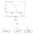
- FIG. 3 illustrates an exemplary frame error rate (FER) performance curve containing waterfall region 301 and error floor region 302 of an irregular LDPC code.
- FER frame error rate
- the invention discloses an interleaving approach in which for LDPC coded bits with any level of reliability, a portion of lower level modulation bits and a portion of higher level modulation bits are mapped. Given a specific structure of an LDPC code and the modulation method, the optimal portion of lower and higher level modulation bits can be determined through a theoretical algorithm called density evolution.
- a digital communications system to interleave bits in a 16ASPK modulation system with FEC code, comprising a transmitter to generate signal waveforms across a communication channel to a receiver, the transmitter having a message source to generate a set of discrete bits which has a corresponding signal waveform; and an LDPC encoder to generate signals from alphabet to a signal mapper, wherein interleaving is a non-consecutive mapping that generates the best threshold of corresponding LDPC codes predicted by density evolution.
- the LDPC codes in the invention have good threshold which reduce transmission power for a given FER performance.
- the threshold of an LDPC code is defined as the smallest SNR value at which, as the codeword length tends to infinity, the bit error probability can be made arbitrarily small.
- FIG. 1 is a parity check matrix representation of an exemplary irregular LDPC code of codeword length six.
- FIG. 2 illustrates a bipartite graph representation of the irregular LDPC code illustrated in FIG. 1.
- FIG. 3 illustrates an exemplary FER performance curve including waterfall and error floor region of an irregular LDPC code.
- FIG. 4 is an exemplary communications system which employs LDPC codes and interleavor/deinterleavor, according to an embodiment of the invention.
- FIG. 5 illustrates an exemplary transmitter in FIG. 4.
- FIG. 5 depicts an exemplary transmitter 401; 500 in the communications system of FIG. 4 which employs LDPC codes and interleaver.
- the LDPC encoder 502 encodes information bits from source 501 into LDPC codewords. The mapping from each information block to each LDPC codeword is specified by the parity check matrix (or equivalently the generator matrix) of the LDPC code.
- the LDPC codeword is interleaved and modulated to signal waveforms by the interleaver/modulator 503. These signal waveforms are sent to a transmit antenna 504 and propagated to a receiver shown in FIG. 6.
- FIG. 6 depicts an exemplary receiver 403; 600 in the communications system of FIG. 4 which employs LDPC codes and a deinterleaver.
- Signal waveforms are received by the receiving antenna 601 and distributed to demodulator/deinterleavor 602.
- Signal waveforms are demodulated by demodulator and deinterleaved by deinterleavor and then distributed to a LDPC decoder 603 which iteratively decodes the received messages and output estimations of the transmitted codeword.
- the deinterleaving rule employed by the demodulator/deinterleaver 602 should match with the interleaving rule employed by the interleaver/modulator 503. That is to say, the deinterleaving scheme should follow an anti-rule of the interleaving scheme.
- the optimal interleaving as the non-consecutive mapping arrangement which generate the best threshold of the corresponding LDPC code predicted by density evolution.
- the mapping logic is shown in FIG. 8.
Abstract
Description
- The invention relates to interleaving low-density parity-check (LDPC) encoded bits in 16APSK (adaptive phase-shift keying) modulation systems. In particular, by assigning the bits determining modulation symbols based on different bit degrees, the desirable tradeoff between error performance and error floor provided by the LDPC codes in use can be efficiently found.
- In " Bit-Reliability Mapping in LDPC-Codes Modulation systems," Yan Li and William Ryan, IEEE Communications Letters, vol. 9, no. 1, January 2005, the authors studied the performance of LDPC-coded modulation systems with 8PSK (phase-shift keying). With the proposed bit reliability mapping strategy, about 0.15 dB performance improvement over a non-interleaving scheme is achieved. The authors also explain the reason for this improvement using an analysis tool called EXIT charts. In the interleaving approach, one interleaving approach is considered and has been shown to offer a better performance over non-interleaving systems, i.e. in the bit-reliability mapping scheme less reliable LDPC code bits are mapped to the lower level modulation bits and the more reliable bits are mapped to the higher level bits.
- Forward error control (FEC) coding is critical for communications systems to ensure reliable transmission of data across noisy communication channels. Based on Shannon's theory, these communication channels exhibit fixed capacity that can be expressed in terms of bits per symbol at certain signal-to-noise ratio (SNR), which is defined as the Shannon limit. One of the most important research areas in communication and coding theory is to devise coding schemes offering performance approaching the Shannon limit with reasonable complexity. It has been shown that LDPC codes with belief propagation (BP) decoding provide performance close to the Shannon limit with tractable encoding and decoding complexity.
- LDPC codes were first described by Gallager in the 1960s. LDPC codes perform remarkably close to the Shannon limit. A binary (N, K) LDPC code, with a code length N and dimension K, is defined by a parity check matrix H of (N-K) rows and N columns. Most entries of the matrix H are zeros and only a small number the entries are ones, hence the matrix H is sparse. Each row of the matrix H represents a check sum, and each column represents a variable, e.g. a bit or symbol. The LDPC codes described by Gallager are regular, i.e. the parity check matrix H has constant-weight rows and columns.
- Regular LDPC codes can be extended to irregular LDPC codes, in which the weight of rows and columns vary. An irregular LDPC code is specified by degree distribution polynomials v(x) and c(x), which define the variable and check node degree distributions, respectively. More specifically, let


where the variables d v max and d c max are a maximum variable node degree and a check node degree, respectively, and vj (cj ) represents the fraction of edges emanating from variable (check) nodes of degree j. - While irregular LDPC codes can be more complicated to represent and/or implement, it has been shown, both theoretically and empirically, that irregular LDPC codes with properly selected degree distributions outperform regular LDPC codes. FIG. 1 illustrates a parity check matrix representation of an exemplary irregular LDPC code of codeword length six.
- LDPC codes can also be represented by bipartite graphs, or Tanner graphs. In a Tanner graph, one set of nodes called variable nodes (or bit nodes) corresponds to the bits of the codeword and the other set of nodes called constraints nodes (or check nodes) corresponds the set of parity check constrains which define the LDPC code. Bit nodes and check nodes are connected by edges. A bit node and a check node is said to be neighbors or adjacent if they are connected by an edge. Generally, it is assumed that a pair of nodes is connected by at most one edge.
- FIG. 2 illustrates a bipartite graph representation of the irregular LDPC code illustrated in FIG. 1. The LDPC code represented by FIG. 1 is of codeword length 6 and has 4 parity checks. As shown in FIG. 1, there are a total of 9 ones in the parity check matrix representation of the LDPC code. Therefore in the Tanner graph representation shown in FIG. 2, 6
bit nodes 201 are connected to 4check nodes 202 by 9edges 203. - LDPC codes can be decoded in various ways, such as majority-logic decoding and iterative decoding. Due to the structures of their parity check matrices, LDPC codes are majority-logic decodable. Majority-logic decoding requires the least complexity and achieves reasonably good error performance for decoding, such as for LDPC codes with relatively high column weights in their parity check matrices (e. g. Euclidean geometry LDPC and projective geometry LDPC codes), whereas iterative decoding methods have received more attentions due to their better performance versus complexity tradeoffs. Unlike majority-logic decoding, iterative decoding processes the received symbols recursively to improve the reliability of each symbol based on constraints that specify the code. In the first iteration, the iterative decoder uses the channel output as input, and generates reliability output for each symbol. Subsequently, the output reliability measures of the decoded symbols at the end of each decoding iteration are used as inputs for the next iteration. The decoding process continues until a certain stopping condition is satisfied. Then final decisions are made, based on the output reliability measures of the decoded symbols from the last iteration. According to the different properties of reliability measures used at each iteration, iterative decoding algorithms can be further divided into hard decision, soft decision and hybrid decision algorithms. The corresponding popular algorithms are iterative bit-flipping (BF), belief propagation (BP), and weighted bit-flipping (WBF) decoding, respectively. The BP algorithm has been proven to provide maximum likelihood decoding given the underlying Tanner graph is acyclic. Therefore, it realistically becomes the most popular decoding method. The invention described below, however, only discusses BP decoding of LDPC codes.
- BP for LDPC codes is a kind of message passing decoding. Messages transmitted along the edges of the graph are log-likelihood ratio (LLR)

value - Because of its remarkable performance with BP decoding, irregular LDPC codes are among the best for many applications. Various irregular LDPC codes have been accepted or being considered for various communication and storage standards, such as DVB-S2/DAB, wireline ADSL, IEEE 802.1 In, and IEEE 802.16 [4][5]. While considering applying irregular LDPC codes to video broadcasting systems, one often encounter a trouble called error floor.
- The error floor performance region of an LDPC decoder can be described by the error performance curve of the system. The LDPC decoder system typically exhibits sharp decrease in error probability as the quality of the input signal improves. The resulting error performance curves are conventionally called waterfall curve and the corresponding region is called waterfall region. At some point, however, the decrease of error probability with input signal quality increase decreases. The resulting flat error performance curve is called error floor.
FIG. 3 illustrates an exemplary frame error rate (FER) performance curve containingwaterfall region 301 anderror floor region 302 of an irregular LDPC code. - It is an object of the invention to present improved digital communications transmitter, reciever and method. This object is achieved by the subject matter of the independent claims.
- The invention discloses an interleaving approach in which for LDPC coded bits with any level of reliability, a portion of lower level modulation bits and a portion of higher level modulation bits are mapped. Given a specific structure of an LDPC code and the modulation method, the optimal portion of lower and higher level modulation bits can be determined through a theoretical algorithm called density evolution.
- In one embodiment of the invention, there is a digital communications system to interleave bits in a 16ASPK modulation system with FEC code, comprising a transmitter to generate signal waveforms across a communication channel to a receiver, the transmitter having a message source to generate a set of discrete bits which has a corresponding signal waveform; and an LDPC encoder to generate signals from alphabet to a signal mapper, wherein interleaving is a non-consecutive mapping that generates the best threshold of corresponding LDPC codes predicted by density evolution.
- Using carefully selected check and bit node degree distributions and Tanner graph constructions, the LDPC codes in the invention have good threshold which reduce transmission power for a given FER performance.
- The threshold of an LDPC code is defined as the smallest SNR value at which, as the codeword length tends to infinity, the bit error probability can be made arbitrarily small.
- Different applications have different requirements for the thresholds and error floor of LDPC codes. Therefore, it is desired to develop a method to determine the mapping scheme in 16APSK systems to provide required threshold while keeping error floor lower than specific criteria.
- The invention is illustrated by way of example, and not by way of limitation, in the figures of the corresponding drawings and in which like reference numerals refer to similar elements and in which:
- FIG. 1 is a parity check matrix representation of an exemplary irregular LDPC code of codeword length six.
- FIG. 2 illustrates a bipartite graph representation of the irregular LDPC code illustrated in FIG. 1.
- FIG. 3 illustrates an exemplary FER performance curve including waterfall and error floor region of an irregular LDPC code.
- FIG. 4 is an exemplary communications system which employs LDPC codes and interleavor/deinterleavor, according to an embodiment of the invention.
- FIG. 5 illustrates an exemplary transmitter in FIG. 4.
- FIG. 6 illustrates an exemplary receiver in FIG. 4.
- FIG. 7 illustrates the bit mapping block in 16APSK modulation.
- FIG. 8 illustrates the bit mapping for 16APSK symbol.
- Referring to the accompanying drawings, a detailed description will be given of encoded bit mapping methods using LDPC codes and program for executing this method according to embodiments of the invention.
- Although the invention is described with respect to LDPC codes, it is recognized that the bit labeling approach can be utilized with other codes. Further, this approach can be implemented with uncoded systems.
- FIG. 4 is a diagram of a communications system employing LDPC codes with an interleaver, according to an embodiment of the invention. The communications system includes a
transmitter 401 which generates signal waveforms across acommunication channel 402 to areceiver 403. Thetransmitter 401 includes a message source producing a discrete set of possible messages. Each of these messages corresponds a signal waveform. The waveforms enter thechannel 402 and are corrupted by noise. LDPC codes are employed to reduce the disturbances introduced by thechannel 402. Given an LDPC code and the desired error floor level, an interleaver and a deinterleaver are used in thetransmitter 401 and thereceiver 403, respectively, based on an interleaving rule to produce a good threshold. - FIG. 5 depicts an
exemplary transmitter 401; 500 in the communications system of FIG. 4 which employs LDPC codes and interleaver. TheLDPC encoder 502 encodes information bits fromsource 501 into LDPC codewords. The mapping from each information block to each LDPC codeword is specified by the parity check matrix (or equivalently the generator matrix) of the LDPC code. The LDPC codeword is interleaved and modulated to signal waveforms by the interleaver/modulator 503. These signal waveforms are sent to a transmitantenna 504 and propagated to a receiver shown in FIG. 6. - FIG. 6 depicts an
exemplary receiver 403; 600 in the communications system of FIG. 4 which employs LDPC codes and a deinterleaver. Signal waveforms are received by the receivingantenna 601 and distributed to demodulator/deinterleavor 602. Signal waveforms are demodulated by demodulator and deinterleaved by deinterleavor and then distributed to aLDPC decoder 603 which iteratively decodes the received messages and output estimations of the transmitted codeword. The deinterleaving rule employed by the demodulator/deinterleaver 602 should match with the interleaving rule employed by the interleaver/modulator 503. That is to say, the deinterleaving scheme should follow an anti-rule of the interleaving scheme. - Given an LDPC code and 16APSK modulation scheme, we define the optimal interleaving as the non-consecutive mapping arrangement which generate the best threshold of the corresponding LDPC code predicted by density evolution.
- As shown in FIG. 7, the 16APSK bit-to-symbol mapping circuit takes four bits (b 4i , b 4i+1, b 4i+2, b 4i+3) each time and maps them into an I value and a Q value, with i=0, 1, 2, ... The mapping logic is shown in FIG. 8.
- In 16APSK, let (b̃i b̃ i+1 b̃ i+2 b̃ i+3) be the 4 bits determining the i-th symbol, for i∈{i|0≤i≤Nldpc_bits -1, and imod4 = 0}. We specify a Noffset to define the number of bit mapping for each code rate. Given an LDPC code and the requirement of level of error floor, there is an optimal interleaving scheme obtained through density evolution analysis. For the LDPC codes with
rate 2/3, ¾, 4/5, 5/6, 13/15, and 9/10 the interleaving rule for 16APSK is:
- The numbers of bit offset is summarized in Table 1: Offset values for interleaving in 16APSK.
Table 1: Offset values for interleaving in 16APSK. Rate N offset 2/3 80 3/4 88 4/5 96 5/6 104 13/15 112 9/10 120 - Although the invention has been described by the way of examples of preferred embodiments, it is to be understood that various other adaptations and modifications may be made within the spirit and scope of the invention. Therefore, it is the object of the appended claims to cover all such variations and modifications as come within the true spirit and scope of the invention.
- Although specific embodiments have been illustrated and described herein, it will be appreciated by those of ordinary skill in the art, that any arrangement which is calculated to achieve the same purpose may be substituted for the specific embodiments shown. It is to be understood, that the above description is intended to be illustrative and not restrictive. This application is intended to cover any adaptations or variations of the invention. Combinations of the above embodiments and many other embodiments will be apparent to those of skill in the art upon reading and understanding the above description. The scope of the invention includes any other embodiments and applications in which the above structures and methods may be used. The scope of the invention should, therefore, be determined with reference to the appended claims along with the full scope of equivalents to which such claims are entitled.
Claims (6)
- A digital communications transmitter (401; 500) interleaving LDPC encoded bits in a 16APSK modulation system based on a rule:

Rate Noffset 2/3 80 3/4 88 4/5 96 5/6 104 13/15 112 9/10 120 - A digital communications receiver (403; 600) deinterleaving LDPC encoded bits in a 16APSK modulation system based on a rule:

Rate Noffset 2/3 80 3/4 88 4/5 96 5/6 104 13/15 112 9/10 120 - A digital communications system comprising the transmitter (401; 500) of claim 1 or the receiver (403; 600) of claim 2 or both.
- The digital communications system claim 3, wherein the digital communications system is a video broadcasting system.
- A digital communications method, comprising:interleaving or deinterleaving LDPC encoded bits in a 16APSK modulation system base on a rule:

Rate Noffset 2/3 80 3/4 88 4/5 96 5/6 104 13/15 112 9/10 120 - A computer-readable medium storing a computer program for performing a method specifying an interleaving scheme of LDPC encoded bits in a 16APSK modulation system base on a rule:

Rate Noffset 2/3 80 3/4 88 4/5 96 5/6 104 13/15 112 9/10 120
Applications Claiming Priority (1)
| Application Number | Priority Date | Filing Date | Title |
|---|---|---|---|
| PCT/CN2006/002421 WO2008034286A1 (en) | 2006-09-18 | 2006-09-18 | An interleaving scheme for an ldpc coded 16apsk system |
Publications (1)
| Publication Number | Publication Date |
|---|---|
| EP1901434A1 true EP1901434A1 (en) | 2008-03-19 |
Family
ID=38565559
Family Applications (1)
| Application Number | Title | Priority Date | Filing Date |
|---|---|---|---|
| EP07016673A Ceased EP1901434A1 (en) | 2006-09-18 | 2007-08-24 | An interleaving scheme for a LDPC coded 16APSK system |
Country Status (4)
| Country | Link |
|---|---|
| US (1) | US8028219B2 (en) |
| EP (1) | EP1901434A1 (en) |
| TW (1) | TWI325259B (en) |
| WO (1) | WO2008034286A1 (en) |
Families Citing this family (11)
| Publication number | Priority date | Publication date | Assignee | Title |
|---|---|---|---|---|
| WO2008034287A1 (en) * | 2006-09-18 | 2008-03-27 | Juntan Zhang | An interleaving scheme for an ldpc coded 32apsk system |
| US8230299B2 (en) * | 2006-09-18 | 2012-07-24 | Availink, Inc. | Interleaving scheme for an LDPC coded QPSK/8PSK system |
| US8370711B2 (en) | 2008-06-23 | 2013-02-05 | Ramot At Tel Aviv University Ltd. | Interruption criteria for block decoding |
| JP2012151676A (en) * | 2011-01-19 | 2012-08-09 | Jvc Kenwood Corp | Decoding apparatus and decoding method |
| US9602137B2 (en) * | 2014-02-19 | 2017-03-21 | Samsung Electronics Co., Ltd. | Transmitting apparatus and interleaving method thereof |
| US10326471B2 (en) * | 2014-05-22 | 2019-06-18 | Electronics And Telecommunications Research Institute | Bit interleaver for low-density parity check codeword having length of 16200 and code rate of 3/15 and quadrature phase shift keying, and bit interleaving method using same |
| KR102287620B1 (en) | 2015-02-16 | 2021-08-10 | 한국전자통신연구원 | Bit interleaver for 1024-symbol mapping and low density parity check codeword with 64800 length, 2/15 rate, and method using the same |
| KR102287629B1 (en) * | 2015-02-16 | 2021-08-10 | 한국전자통신연구원 | Bit interleaver for 4096-symbol mapping and low density parity check codeword with 64800 length, 3/15 rate, and method using the same |
| US9847794B2 (en) * | 2015-05-19 | 2017-12-19 | Samsung Electronics Co., Ltd. | Transmitting apparatus and interleaving method thereof |
| CN111064691B (en) | 2016-01-27 | 2024-02-09 | 华为技术有限公司 | Transmitter, receiver and signal processing method |
| US11043969B2 (en) * | 2019-11-12 | 2021-06-22 | SK Hynix Inc. | Fast-converging soft bit-flipping decoder for low-density parity-check codes |
Family Cites Families (8)
| Publication number | Priority date | Publication date | Assignee | Title |
|---|---|---|---|---|
| JPS60206284A (en) | 1984-03-30 | 1985-10-17 | Nippon Hoso Kyokai <Nhk> | Transmission system of still picture signal |
| JP3974712B2 (en) | 1998-08-31 | 2007-09-12 | 富士通株式会社 | Digital broadcast transmission / reception reproduction method, digital broadcast transmission / reception reproduction system, digital broadcast transmission apparatus, and digital broadcast reception / reproduction apparatus |
| KR20020001039A (en) | 2000-06-23 | 2002-01-09 | 서평원 | Service Method And Apparatus For Internet Satellite Broadcast Using Internet And Satellite Network |
| DE10134764A1 (en) | 2001-07-13 | 2003-01-30 | Deutsche Telekom Ag | Geostationary satellite management system for efficient use of transponder bandwidth, adapts modulation power and mode automatically, in terms of quality and noise parameters |
| EP1525664B9 (en) * | 2002-07-03 | 2015-09-02 | Dtvg Licensing, Inc | Method and system for memory management in low density parity check (ldpc) decoders |
| US7577207B2 (en) * | 2002-07-03 | 2009-08-18 | Dtvg Licensing, Inc. | Bit labeling for amplitude phase shift constellation used with low density parity check (LDPC) codes |
| KR100996029B1 (en) * | 2003-04-29 | 2010-11-22 | 삼성전자주식회사 | Apparatus and method for coding of low density parity check code |
| US7251769B2 (en) * | 2004-03-17 | 2007-07-31 | Lucent Technologies Inc. | Methods and apparatus for communication using generalized low density parity check codes |
-
2006
- 2006-09-18 WO PCT/CN2006/002421 patent/WO2008034286A1/en active Application Filing
- 2006-09-18 US US11/813,201 patent/US8028219B2/en not_active Expired - Fee Related
-
2007
- 2007-03-07 TW TW096107917A patent/TWI325259B/en not_active IP Right Cessation
- 2007-08-24 EP EP07016673A patent/EP1901434A1/en not_active Ceased
Non-Patent Citations (1)
| Title |
|---|
| LI Y ET AL: "BIT-RELIABILITY MAPPING IN LDPC-CODED MODULATION SYSTEMS", IEEE COMMUNICATIONS LETTERS, IEEE SERVICE CENTER, PISCATAWAY, NJ, US, vol. 9, no. 1, January 2005 (2005-01-01), pages 1 - 3, XP001211457, ISSN: 1089-7798 * |
Also Published As
| Publication number | Publication date |
|---|---|
| TWI325259B (en) | 2010-05-21 |
| US8028219B2 (en) | 2011-09-27 |
| TW200816732A (en) | 2008-04-01 |
| US20110107183A1 (en) | 2011-05-05 |
| WO2008034286A1 (en) | 2008-03-27 |
Similar Documents
| Publication | Publication Date | Title |
|---|---|---|
| US8369448B2 (en) | Bit mapping scheme for an LDPC coded 32APSK system | |
| US8028219B2 (en) | Interleaving scheme for an LDPC coded 16APSK system | |
| US8230299B2 (en) | Interleaving scheme for an LDPC coded QPSK/8PSK system | |
| US7802164B2 (en) | Apparatus and method for encoding/decoding block low density parity check codes having variable coding rate | |
| US8689092B2 (en) | Family of LDPC codes for video broadcasting applications | |
| US7222284B2 (en) | Low-density parity-check codes for multiple code rates | |
| US7555694B2 (en) | Channel interleaving/de-interleaving apparatus in a communication system using a low density parity check code and control method thereof | |
| EP2088678B1 (en) | Method and apparatus for channel encoding and decoding in a communication system using low-density parity-check codes | |
| EP2510623B1 (en) | Method and apparatus for channel encoding and decoding in a communication system using a low-density parity check code | |
| US8301960B2 (en) | Interleaving scheme for an LDPC coded 32 APSK system | |
| CN101150551B (en) | Interweaving scheme of QPSK/8PSK system for low-density checksum coding | |
| CN101150378B (en) | Interleaving scheme of 32APSK system for low-density checksum coding | |
| US7559010B2 (en) | Short length LDPC (Low Density Parity Check) code and modulation adapted for high speed Ethernet applications | |
| CN101150377A (en) | Bit mapping scheme of 32APSK system for low-density checksum coding | |
| CN101150550B (en) | Method for interweaving low-density parity check code bit, transmitter and receiver | |
| US7458003B2 (en) | Low-complexity, capacity-achieving code for communication systems | |
| EP1901438A2 (en) | An interleaving scheme for a LDPC coded QPSK/8PSK system | |
| EP1901436A2 (en) | Bit mapping scheme for an LDPC coded 16APSK system | |
| US20110173509A1 (en) | Bit mapping scheme for an ldpc coded 16apsk system | |
| Hekim et al. | Performance of low density parity check coded continuous phase frequency shift keying (LDPCC‐CPFSK) over fading channels | |
| CN101150552A (en) | Bit mapping scheme of 16APSK system for low-density parity check coding |
Legal Events
| Date | Code | Title | Description |
|---|---|---|---|
| PUAI | Public reference made under article 153(3) epc to a published international application that has entered the european phase |
Free format text: ORIGINAL CODE: 0009012 |
|
| AK | Designated contracting states |
Kind code of ref document: A1 Designated state(s): AT BE BG CH CY CZ DE DK EE ES FI FR GB GR HU IE IS IT LI LT LU LV MC MT NL PL PT RO SE SI SK TR |
|
| AX | Request for extension of the european patent |
Extension state: AL BA HR MK YU |
|
| 17P | Request for examination filed |
Effective date: 20080918 |
|
| AKX | Designation fees paid |
Designated state(s): AT BE BG CH CY CZ DE DK EE ES FI FR GB GR HU IE IS IT LI LT LU LV MC MT NL PL PT RO SE SI SK TR |
|
| 17Q | First examination report despatched |
Effective date: 20081121 |
|
| STAA | Information on the status of an ep patent application or granted ep patent |
Free format text: STATUS: THE APPLICATION HAS BEEN REFUSED |
|
| 18R | Application refused |
Effective date: 20101123 |