EP1900323B1 - Medical electrode - Google Patents
Medical electrode Download PDFInfo
- Publication number
- EP1900323B1 EP1900323B1 EP07017727A EP07017727A EP1900323B1 EP 1900323 B1 EP1900323 B1 EP 1900323B1 EP 07017727 A EP07017727 A EP 07017727A EP 07017727 A EP07017727 A EP 07017727A EP 1900323 B1 EP1900323 B1 EP 1900323B1
- Authority
- EP
- European Patent Office
- Prior art keywords
- skin
- connection piece
- holding element
- electrically conducting
- adhesive
- Prior art date
- Legal status (The legal status is an assumption and is not a legal conclusion. Google has not performed a legal analysis and makes no representation as to the accuracy of the status listed.)
- Active
Links
- 239000000853 adhesive Substances 0.000 claims abstract description 22
- 230000001070 adhesive effect Effects 0.000 claims abstract description 22
- 238000007789 sealing Methods 0.000 claims abstract description 15
- 238000000034 method Methods 0.000 claims abstract description 9
- 229920001169 thermoplastic Polymers 0.000 claims abstract description 3
- 239000004416 thermosoftening plastic Substances 0.000 claims abstract description 3
- 210000000744 eyelid Anatomy 0.000 abstract 1
- 238000010438 heat treatment Methods 0.000 description 6
- 239000004020 conductor Substances 0.000 description 3
- 239000012790 adhesive layer Substances 0.000 description 2
- 238000001816 cooling Methods 0.000 description 2
- 239000010410 layer Substances 0.000 description 2
- 229920000049 Carbon (fiber) Polymers 0.000 description 1
- 239000004831 Hot glue Substances 0.000 description 1
- 229910021607 Silver chloride Inorganic materials 0.000 description 1
- 206010040880 Skin irritation Diseases 0.000 description 1
- 239000004917 carbon fiber Substances 0.000 description 1
- 239000007933 dermal patch Substances 0.000 description 1
- 238000009792 diffusion process Methods 0.000 description 1
- 230000002349 favourable effect Effects 0.000 description 1
- 239000006260 foam Substances 0.000 description 1
- 230000001771 impaired effect Effects 0.000 description 1
- 238000004519 manufacturing process Methods 0.000 description 1
- 230000001681 protective effect Effects 0.000 description 1
- HKZLPVFGJNLROG-UHFFFAOYSA-M silver monochloride Chemical compound [Cl-].[Ag+] HKZLPVFGJNLROG-UHFFFAOYSA-M 0.000 description 1
- 230000036556 skin irritation Effects 0.000 description 1
- 231100000475 skin irritation Toxicity 0.000 description 1
- 239000007787 solid Substances 0.000 description 1
- 238000007711 solidification Methods 0.000 description 1
- 230000008023 solidification Effects 0.000 description 1
Images

Classifications
-
- A—HUMAN NECESSITIES
- A61—MEDICAL OR VETERINARY SCIENCE; HYGIENE
- A61B—DIAGNOSIS; SURGERY; IDENTIFICATION
- A61B5/00—Measuring for diagnostic purposes; Identification of persons
- A61B5/24—Detecting, measuring or recording bioelectric or biomagnetic signals of the body or parts thereof
- A61B5/25—Bioelectric electrodes therefor
- A61B5/251—Means for maintaining electrode contact with the body
- A61B5/257—Means for maintaining electrode contact with the body using adhesive means, e.g. adhesive pads or tapes
-
- A—HUMAN NECESSITIES
- A61—MEDICAL OR VETERINARY SCIENCE; HYGIENE
- A61B—DIAGNOSIS; SURGERY; IDENTIFICATION
- A61B5/00—Measuring for diagnostic purposes; Identification of persons
- A61B5/24—Detecting, measuring or recording bioelectric or biomagnetic signals of the body or parts thereof
- A61B5/25—Bioelectric electrodes therefor
- A61B5/263—Bioelectric electrodes therefor characterised by the electrode materials
- A61B5/266—Bioelectric electrodes therefor characterised by the electrode materials containing electrolytes, conductive gels or pastes
-
- A—HUMAN NECESSITIES
- A61—MEDICAL OR VETERINARY SCIENCE; HYGIENE
- A61N—ELECTROTHERAPY; MAGNETOTHERAPY; RADIATION THERAPY; ULTRASOUND THERAPY
- A61N1/00—Electrotherapy; Circuits therefor
- A61N1/02—Details
- A61N1/04—Electrodes
- A61N1/0404—Electrodes for external use
- A61N1/0472—Structure-related aspects
- A61N1/048—Electrodes characterised by a specific connection between lead and electrode
-
- A—HUMAN NECESSITIES
- A61—MEDICAL OR VETERINARY SCIENCE; HYGIENE
- A61N—ELECTROTHERAPY; MAGNETOTHERAPY; RADIATION THERAPY; ULTRASOUND THERAPY
- A61N1/00—Electrotherapy; Circuits therefor
- A61N1/02—Details
- A61N1/04—Electrodes
- A61N1/0404—Electrodes for external use
- A61N1/0472—Structure-related aspects
- A61N1/0492—Patch electrodes
Definitions
- the invention relates to a medical electrode for application to the skin surface of a subject, having a skin-side adhesive carrier and a holding element for at least one electrically conductive connection piece, wherein the half-element is adhesively bonded to the electrically conductive connection piece, wherein the connection piece is provided on the skin side with an electrically conductive gel. especially in a sponge - is covered. Furthermore, the invention relates to a method for producing a medical electrode.
- ECG electrodes which can be stuck onto the skin surface of a subject consist of a skin-side adhesive carrier layer with a recess into which an electrically conductive gel (in particular embedded in a sponge) is usually introduced ,
- the gel is in electrically conductive contact with an electrically conductive connector, which is often referred to as a sensor element or eyelet.
- Generic electrodes reveal, for example, the US 3,989,035 or the US 4,522.21.1 ,
- the fitting may e.g. consist of an approximately disc-shaped base body with an approximately cylindrical projection.
- the projection extends through a recess in the holding element while the base body is glued to the holding element.
- the connecting piece is connected to an electrical conductor, for example a cable, in order to transmit signals from or to the electrode via, for example, an electrocardiograph.
- the sensor element is fixed on one side (and with the skin-facing side of the disc-shaped base body) in direct contact with the gel and on the opposite side so with the side facing away from the skin on the holding element.
- the retaining element may e.g. be present as a label and fixed on the carrier.
- the electrically conductive gel diffuses between the connection piece and the holding element, thereby dissolving the connection between the two (eg in the form of an adhesive).
- the function and the accuracy of the electrode are impaired, which means that the electrode may become completely unusable as a result.
- Object of the present invention is therefore to improve a medical electrode of the type mentioned so that a longer shelf life is given. Furthermore, the mechanical strength for further processing or application is to be improved.
- thermoactivatable adhesive is, for example, a so-called hotmelt adhesive, which is made processable by increasing the temperature and, when the adhesive cools and solidifies, produces a solid and functional bond.
- a nonwoven impregnated with a thermoactivatable adhesive is particularly advantageous for the stepwise processing (as will be explained in detail in the method described below), since such a thermally activatable adhesive can be heated several times and thereby made processable.
- the sensor element is completely covered by a conductive surface, preferably Ag / AgCl, wherein it is further favorable if the plastifiable main body of the sensor element comprises ABS, and if the sensor element contains carbon fibers in an amount of less than 30%. , preferably about 20%.
- the sealing element is a thermoplastic film, which is plasticized by heating, so that a seal after hardening of the film by cooling takes place.
- the Fig. 1a shows an embodiment of a medical electrode according to the invention in cross section.
- This electrode consists of a carrier 1, which consists in the present case of a foam.
- This carrier 1 has an adhesive layer 8 on the skin side so that the electrode can be adhered to the skin surface (not shown).
- the adhesive layer 8 should be made skin-friendly, so that no skin irritation when sticking to the skin, similar to a skin patch.
- a retaining element 2 in the form of a label which is connected to the carrier 1 by means of a thermoactivatable adhesive 9.
- Sponge 5 electric gel and sensor element 3 are all introduced into the recess 11 of the carrier 1 and complete approximately flush with the underside of the carrier 1 (skin side), optionally, as shown, the compressible sponge 5 together with electric gel slightly above the Carrier 1 protrude so that when glued on the skin state of the sponge is pressed flush into the recess 11.
- a release liner 14 protects the electrode on the skin side before use. For use, the release liner is removed.
- the sponge 5 is also connected to the sensor element 3 via the thermoactivatable adhesive 9. For this purpose, an approximately annular region on the sensor element 3 is covered with adhesive 9 and the sponge 5 is placed after heating the adhesive 9. After solidification of the adhesive, the sponge 5 is permanently connected to the electrode (or the sensor element).
- the outer shape of the carrier 1 and the recess 11 are each formed approximately circular in the present case, so that the carrier 1 forms a circular ring.
- the invention is not limited to this form.
- oval or angular outer shapes for the carrier 1 and decentralized, non-circular recesses 11, etc. are conceivable.
- the shape of the recess 11 depends essentially on the intended use and of the shape of the sensor element 3 and of the shape of the sponge 5, which is introduced into the recess 11.
- Carrier 1 and retaining element 2 for the sensor element 3 could of course also be formed in one piece within the scope of the invention.
- the sensor element 3 in this case has a main body with which it is also connected to the holding element 2 via the thermoactivatable adhesive 9.
- the holding element 2 additionally has a recess 6, through which the approximately cylindrical projection of the sensor element 3 extends. At this projection of the connecting piece of the electrical conductor 7 (as a cable with multiple strands) is mounted in the operating state, the signals to the electrocardiograph, not shown passes.
- the gap 15 is located between the side of the carrier facing the skin surface and the side of the connection piece facing away from the skin surface. At least the gel penetrates into the adhesive after a certain time and thus impairs the connection between connection piece 3 and Retaining element 2.
- an annular sealing element 4 in the present case from a nonwoven impregnated with a thermally activated adhesive, the diffusion of the electrically conductive gel can be completely prevented.
- the gap is in this case between the underside of the holding element 3 (ie the side of the holding element 3, which is directed in glued or attached state to the skin) and the electrically conductive connector 3.
- the Fig. 1b shows a view from above of the electrode Fig. 1 a. Visible are the carrier 1, the holding element 2, as well as the cylindrical projection of the connecting piece 3, from which the electrical conductor 7 leads away.
- Fig. 1c are visible in the bottom view of the electrode, only the carrier 1 and the sponge 5 with electrically conductive gel.
- transparent release liner 14 is arranged, which protects the electrode. A recess facilitates the removal of the release liner 14th
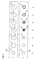
- FIG. 2 Let an embodiment of a method according to the invention briefly described.
- the letters A to H denote the individual process steps, the representation O describes the view from above and the representation U the view from below.
- C In step 3, a circular recess 6, which is significantly smaller than the recess 11, is then punched approximately in the middle of the holding element 2.
- step 5 the very essential step now takes place, namely that the sealing element 4 in the form of a fixing ring is pushed concentrically over the sensor element 2 from below. By heating the sealing member 4 is fixed to the support member 3 and the sensor element 2, and sealed.
- the sponge 5 is pushed over the into the recess 11 via the connecting piece 3 and the sealing element and also sealed with the connector 3, also by heating, by a thermooxidierbarer adhesive is on the sensor element 3 in the outer region, by heating liquefied and after cooling a stable connection with the sponge 5 produces.
- the sealing element 4 used is a nonwoven which has been impregnated in a thermoactivatable adhesive, since the adhesive can be activated several times by simple heating.
- the fleece serves as a seal on one side and on the other side for fastening the sponge 5.
- the sponge 5 is now filled with the electrically conductive gel.
- H Finally, a protective or covering film 14 is applied and then the electrodes are punched out.
Landscapes
- Health & Medical Sciences (AREA)
- Life Sciences & Earth Sciences (AREA)
- Engineering & Computer Science (AREA)
- Biomedical Technology (AREA)
- Animal Behavior & Ethology (AREA)
- General Health & Medical Sciences (AREA)
- Public Health (AREA)
- Veterinary Medicine (AREA)
- Nuclear Medicine, Radiotherapy & Molecular Imaging (AREA)
- Radiology & Medical Imaging (AREA)
- Physics & Mathematics (AREA)
- Biophysics (AREA)
- Pathology (AREA)
- Heart & Thoracic Surgery (AREA)
- Medical Informatics (AREA)
- Molecular Biology (AREA)
- Surgery (AREA)
- Measurement And Recording Of Electrical Phenomena And Electrical Characteristics Of The Living Body (AREA)
- Electrotherapy Devices (AREA)
- Materials For Medical Uses (AREA)
Abstract
Description
Die Erfindung betrifft eine medizinische Elektrode zum Aufbringen auf die Hautoberfläche eines Probanden, mit einem hautseitig haftenden Träger und einem Haltelement für mindestens ein elektrisch leitendes Anschlußstück, wobei das Halbelement mit dem elektrisch leitenden Anschlussstück verklebt ist, wobei das Anschlussstück hautseitig mit einem elektrisch leitenden Gel - insbesondere in einem Schwamm - abgedeckt ist. Weiters betrifft die Erfindung ein Verfahren zur Herstellung einer medizinischen Elektrode.The invention relates to a medical electrode for application to the skin surface of a subject, having a skin-side adhesive carrier and a holding element for at least one electrically conductive connection piece, wherein the half-element is adhesively bonded to the electrically conductive connection piece, wherein the connection piece is provided on the skin side with an electrically conductive gel. especially in a sponge - is covered. Furthermore, the invention relates to a method for producing a medical electrode.
Nach dem Stand der Technik bekannte, auf die Hautoberfläche eines Probanden aufklebbare, medizinischen Elektroden (zB EKG-Elektroden) bestehen aus einer hautseitig klebenden Trägerschicht mit einer Ausnehmung, in die in der Regel ein elektrisch leitendes Gel (insbesondere eingebettet in einem Schwamm) eingebracht wird. (Die Bezeichnung "Proband" ist an dieser Stelle selbstverständlich vollkommen geschlechtsneutral zu verstehen.) Das Gel steht mit einem elektrisch leitenden Anschlussstück, das häufig auch als Sensorelement oder Eyelet bezeichnet wird, in elektrisch leitendem Kontakt. Gattungsgemäße Elektroden offenbaren zum Beispiel die
Das Anschlussstück kann z.B. aus einem etwa scheibenförmigen Grundkörper mit einem etwa zylinderförmigen Vorsprung bestehen. Der Vorsprung reicht durch eine Ausnehmung im Halteelement während der Grundkörper mit dem Halteelement verklebt ist. Am zylinderförmigen Vorsprung ist das Anschlussstück mit einem elektrischen Leiter, beispielsweise einem Kabel verbunden, um Signale von oder zur Elektrode über beispielsweise einen Elektrokardiographen zu übermitteln. Das Sensorelement ist auf einer Seite (und zwar mit der der Haut zugewandten Seite des scheibenförmigen Grundkörpers) in direktem Kontakt mit dem Gel und auf der gegenüberliegenden Seite also mit der der Haut abgewandten Seite am Halteelement fixiert. Das Halteelement kann z.B. als Etikett vorliegen und am Träger fixiert sein.The fitting may e.g. consist of an approximately disc-shaped base body with an approximately cylindrical projection. The projection extends through a recess in the holding element while the base body is glued to the holding element. At the cylindrical projection, the connecting piece is connected to an electrical conductor, for example a cable, in order to transmit signals from or to the electrode via, for example, an electrocardiograph. The sensor element is fixed on one side (and with the skin-facing side of the disc-shaped base body) in direct contact with the gel and on the opposite side so with the side facing away from the skin on the holding element. The retaining element may e.g. be present as a label and fixed on the carrier.
Beim Stand der Technik hat es sich als nachteilhaft erwiesen, dass bei Lagerung der medizinischen Elektrode das elektrisch leitende Gel zwischen Anschlussstück und Halteelement eindiffundiert und dabei die Verbindung zwischen den beiden (z.B. in der Form eines Klebers) auflöst. Dadurch kommt es zu einer Beeinträchtigung der Funktion und der Genauigkeit der Elektrode, unter Umständen wird die Elektrode dadurch vollkommen unbrauchbar.In the prior art, it has proven to be disadvantageous that when storing the medical electrode, the electrically conductive gel diffuses between the connection piece and the holding element, thereby dissolving the connection between the two (eg in the form of an adhesive). As a result, the function and the accuracy of the electrode are impaired, which means that the electrode may become completely unusable as a result.
Aufgabe der vorliegenden Erfindung ist es daher, eine medizinische Elektrode der eingangs genannten Gattung so zu verbessern, dass eine längere Haltbarkeit gegeben ist. Weiters soll die mechanische Festigkeit zur Weiterverarbeitung oder Anwendung verbessert werden.Object of the present invention is therefore to improve a medical electrode of the type mentioned so that a longer shelf life is given. Furthermore, the mechanical strength for further processing or application is to be improved.
Diese Aufgabe wird mit den Merkmalen des Anspruchs 1 oder mit einem Verfahren nach Anspruch 4 gelöst. Indem der hautseitige Spalt zwischen Halteelement und elektrisch leitendem Anschlussstück (d.h. der Spalt zwischen der Unterseite des Halteelementes und dem elektrisch leitenden Anschlussstück) durch ein, vorzugsweise ringförmiges, Siegelelement überdeckt verschlossen ist bzw. mit dem Siegelelement versiegelt wird, kann das elektrisch leitende Gel nicht mehr in den Spalt zwischen das Halteelement und das Anschlussstück bzw. das Sensorelement eindiffundieren und so das Sensorelement vom Halteelement ablösen.This object is achieved by the features of
Dabei hat es sich als vorteilhaft erwiesen, wenn das Siegelelement ein mit einem thermoaktivierbaren Kleber getränktes Vlies ist. Ein thermoaktivierbarer Kleber ist beispielsweise ein so genannter Hotmeltkleber, der durch Temperaturerhöhung verarbeitbar gemacht wird und bei Abkühlen und Erstarren des Klebstoffs eine feste und funktionsfähige Verbindung herstellt. Speziell für die schrittweise Verarbeitung ist ein solches mit einem thermoaktivierbaren Kleber getränktes Vlies vorteilhaft (wie im weiter unten beschriebenen Verfahren noch ausführlich erläutert werden wird) da ein solcher thermoaktivierbarer Kleber mehrfach erhitzt und dadurch verarbeitbar gemacht werden kann.It has proven to be advantageous if the sealing element is a soaked with a thermally activated adhesive fleece. A thermoactivatable adhesive is, for example, a so-called hotmelt adhesive, which is made processable by increasing the temperature and, when the adhesive cools and solidifies, produces a solid and functional bond. Such a nonwoven impregnated with a thermoactivatable adhesive is particularly advantageous for the stepwise processing (as will be explained in detail in the method described below), since such a thermally activatable adhesive can be heated several times and thereby made processable.
Die besten Ergebnisse haben sich erzielen lassen, wenn das Sensorelement vollständig von einer leitfähigen Oberfläche bedeckt ist, vorzugsweise Ag/AgCl, wobei weiters günstig ist, wenn der plastifizierbare Grundkörper des Sensorelements ABS umfasst, sowie wenn das Sensorelement Karbonfasern in einer Menge von unter 30 %, vorzugsweise etwa 20 %, aufweist.The best results have been achieved when the sensor element is completely covered by a conductive surface, preferably Ag / AgCl, wherein it is further favorable if the plastifiable main body of the sensor element comprises ABS, and if the sensor element contains carbon fibers in an amount of less than 30%. , preferably about 20%.
Kostengünstiger könnte vorgesehen sein, dass das Siegelelement eine thermoplastische Folie ist, die durch Erwärmen plastifiziert, sodass eine Versiegelung nach dem Erhärten der Folie durch Abkühlung erfolgt.More cost effective, it could be provided that the sealing element is a thermoplastic film, which is plasticized by heating, so that a seal after hardening of the film by cooling takes place.
Weitere Vorteile und Details der Erfindung werden anhand der vorliegenden Zeichnungen näher erläutert. Dabei zeigen
Weiter mit Seite 3 der Beschreibung der Erfindung
- Fig. 1a, 1b und 1c
- einen Querschnitt, eine Sicht von oben und eine Sicht von unten auf ein Ausführungsbeispiel einer erfindungsgemäßen medizinischen Elektrode sowie
- Fig. 2
- schematisiert Verfahrensschritte eines erfindungsgemäßen Verfahrens.
Continue with
- Fig. 1a, 1b and 1c
- a cross section, a view from above and a view from below of an embodiment of a medical electrode according to the invention and
- Fig. 2
- schematized method steps of a method according to the invention.
Die
Erkennbar ist außerdem ein Halteelement 2 in der Form eines Etikettes, das mittels eines thermoaktivierbaren Klebers 9 mit dem Träger 1 verbunden ist. Der Träger 1 weist über einen größeren Bereich, wo sich das Haltelement 2 befindet, eine Ausnehmung 11 auf, in die ein elektrisch leitendes Anschlussstück 3 (=Sensorelement, Eyelet) geschoben ist. Erkennbar ist weiters der Schwamm 5, in dem sich ein elektrisch leitendes Gel befindet. Das Gel steht an sich im direkten Kontakt zur Haut und gibt dabei Signale weiter an das Sensorelement 3 bzw. umgekehrt. Schwamm 5, elektrisches Gel und Sensorelement 3 sind alle in der Ausnehmung 11 des Trägers 1 eingebracht und schließen insgesamt etwa bündig mit der Unterseite des Trägers 1 (hautseitig) ab, gegebenenfalls kann, wie gezeigt, der kompressible Schwamm 5 samt elektrischem Gel etwas über den Träger 1 vorstehen, sodass im auf die Haut geklebten Zustand der Schwamm bündig in die Ausnehmung 11 eingepresst wird. Eine Abziehfolie 14 schützt die Elektrode hautseitig vor der Benutzung. Zur Benutzung wird die Abziehfolie entfernt. Der Schwamm 5 ist ebenfalls über den thermoaktivierbaren Kleber 9 mit dem Sensorelement 3 verbunden. Dazu ist ein etwa kreisringförmiger Bereich am Sensorelement 3 mit Kleber 9 bedeckt und der Schwamm 5 wird nach Erwärmen des Klebers 9 aufgesetzt. Nach Erstarren des Klebers ist der Schwamm 5 dauerhaft mit der Elektrode (bzw. dem Sensorelement) verbunden.Also recognizable is a retaining element 2 in the form of a label which is connected to the
Die Außenform des Trägers 1 und die Ausnehmung 11 sind im vorliegenden Fall jeweils etwa kreisförmig ausgebildet, sodass der Träger 1 einen Kreisring bildet. Allerdings ist die Erfindung nicht auf diese Form beschränkt. Beispielsweise sind auch ovale oder eckige Außenformen für den Träger 1 sowie dezentrale, nicht-kreisförmige Ausnehmungen 11 usw. denkbar. Die Form der Ausnehmung 11 hängt im Wesentlichen vom Verwendungszweck und von der Form des Sensorelements 3 bzw. von der Form des Schwammes 5 ab, der in die Ausnehmung 11 eingebracht wird. Träger 1 und Halteelement 2 für das Sensorelement 3 könnten im Rahmen der Erfindung selbstverständlich auch einstückig ausgebildet sein. Das Sensorelement 3 weist dabei einen Grundkörper auf mit dem es mit dem Halteelement 2 ebenfalls über den thermoaktivierbaren Kleber 9 verbunden ist. Das Halteelement 2 weist zusätzlich eine Ausnehmung 6 auf, durch das der etwa zylinderförmige Vorsprung des Sensorelements 3 reicht. An diesem Vorsprung des Anschlussstückes ist der elektrische Leiter 7 (als Kabel mit mehreren Litzen) angebracht der im Betriebszustand die Signale an den nicht gezeigten Elektrokardiographen weiterleitet.The outer shape of the
Beim Stand der Technik kann nun im Spaltbereich 15 das elektrisch leitende Gel eindiffundieren und den thermoaktivierbaren Kleber ablösen. Der Spalt 15 befindet sich dabei zwischen der der Hautoberfläche zugewandten Seite des Trägers und der dieser Seite zugewandten, aber der Hautoberfläche abgewandten Seite des Anschlussstückes 3. Zumindest dringt das Gel nach einer gewissen Zeit in den Kleber ein und beeinträchtigt so die Verbindung zwischen Anschlussstück 3 und Halteelement 2. Durch das Einbringen eines im vorliegenden Fall ringförmigen Siegelelementes 4 aus einem mit einem thermoaktivierbaren Kleber getränkten Vlies, lässt sich das Eindiffundieren des elektrisch leitenden Gels vollständig unterbinden. Der Spalt befindet sich dabei zwischen der Unterseite des Halteelementes 3 (d.h. der Seite des Halteelementes 3, die im aufgeklebten oder angebrachten Zustand zur Haut gerichtet ist) und dem elektrisch leitenden Anschlussstück 3. An dieser Stelle sei angemerkt, dass Lageangaben sich auf die in den Figuren dargestellten Normallagen beziehen, bei der die Hautseite unten liegt.In the prior art can now diffuse in the
Die
In der
Anhand der
Claims (4)
- A medical electrode for placing on the skin of a patient, having a support (1) for attaching to the skin and a holding element (2) for at least one electrically conducting connection piece (3), wherein the holding element (2) is glued to the electrically conducting connection piece (3), wherein the connection piece (3) is covered on the skin side with an electrically conducting gel - in particular in a sponge, characterized in that the gap (15) on the skin side between the holding element (2) and the electrically conducting connection piece (3) is covered and closed by a sealing element (4) which is preferably ring-like.
- An electrode according to claim 1, characterized in that the sealing element (4) is a nonwoven impregnated with a heat-activatable adhesive.
- An electrode according to claim 1, characterized in that the sealing element (4) is a thermoplastic film.
- A process for producing a medical electrode according to one of claims 1 to 3. characterized in that the gap (15) between the underside of the holding element (2) and the electrically conducting connection piece (3) is sealed with a sealing element (4).
Applications Claiming Priority (1)
| Application Number | Priority Date | Filing Date | Title |
|---|---|---|---|
| AT0154206A AT503913B1 (en) | 2006-09-15 | 2006-09-15 | MEDICAL ELECTRODE |
Publications (2)
| Publication Number | Publication Date |
|---|---|
| EP1900323A1 EP1900323A1 (en) | 2008-03-19 |
| EP1900323B1 true EP1900323B1 (en) | 2010-01-06 |
Family
ID=38799332
Family Applications (1)
| Application Number | Title | Priority Date | Filing Date |
|---|---|---|---|
| EP07017727A Active EP1900323B1 (en) | 2006-09-15 | 2007-09-11 | Medical electrode |
Country Status (4)
| Country | Link |
|---|---|
| US (1) | US8160673B2 (en) |
| EP (1) | EP1900323B1 (en) |
| AT (2) | AT503913B1 (en) |
| DE (1) | DE502007002537D1 (en) |
Families Citing this family (3)
| Publication number | Priority date | Publication date | Assignee | Title |
|---|---|---|---|---|
| DE102009035018A1 (en) | 2009-07-28 | 2011-02-03 | Dräger Medical AG & Co. KG | Medical sensor device |
| JP6876622B2 (en) | 2015-02-09 | 2021-05-26 | ムラタ バイオス, インク.Murata Vios Inc. | Patient wearing sensor assembly |
| AT519280B1 (en) * | 2016-10-21 | 2019-08-15 | Leonh Lang | Electrode for attachment to human skin |
Family Cites Families (8)
| Publication number | Priority date | Publication date | Assignee | Title |
|---|---|---|---|---|
| US3805769A (en) * | 1971-08-27 | 1974-04-23 | R Sessions | Disposable electrode |
| US3989035A (en) * | 1975-08-04 | 1976-11-02 | Stemmen Laboratory, Inc. | Disposable medical electrode |
| US4029086A (en) * | 1975-08-11 | 1977-06-14 | Consolidated Medical Equipment, Inc. | Electrode arrangement |
| US4522211A (en) * | 1979-12-06 | 1985-06-11 | C. R. Bard, Inc. | Medical electrode construction |
| US5199432A (en) * | 1990-10-30 | 1993-04-06 | American Home Products Corporation | Fetal electrode product for use in monitoring fetal heart rate |
| AT399450B (en) * | 1993-07-19 | 1995-05-26 | Lang Leonhard Dr | METHOD AND DEVICE FOR PRODUCING ELECTRODES |
| AT407342B (en) * | 1999-04-29 | 2001-02-26 | Leonhard Lang Kg | NEUTRAL ELECTRODE |
| US9002473B2 (en) * | 2004-10-29 | 2015-04-07 | Koninklijke Philips N.V. | Electrode and enclosure for cardiac monitoring and treatment |
-
2006
- 2006-09-15 AT AT0154206A patent/AT503913B1/en active
-
2007
- 2007-09-11 AT AT07017727T patent/ATE454086T1/en active
- 2007-09-11 DE DE502007002537T patent/DE502007002537D1/en active Active
- 2007-09-11 EP EP07017727A patent/EP1900323B1/en active Active
- 2007-09-14 US US11/855,225 patent/US8160673B2/en active Active
Also Published As
| Publication number | Publication date |
|---|---|
| AT503913A4 (en) | 2008-02-15 |
| AT503913B1 (en) | 2008-02-15 |
| US8160673B2 (en) | 2012-04-17 |
| DE502007002537D1 (en) | 2010-02-25 |
| US20080071159A1 (en) | 2008-03-20 |
| EP1900323A1 (en) | 2008-03-19 |
| ATE454086T1 (en) | 2010-01-15 |
Similar Documents
| Publication | Publication Date | Title |
|---|---|---|
| DE10315544B4 (en) | Method for producing a piercing and measuring device and device | |
| DE2912161C2 (en) | Skin electrode | |
| DE2754465A1 (en) | EKG ELECTRODE PACK | |
| DE102006032583A1 (en) | introducer | |
| DE2538898A1 (en) | ELECTRODE FOR ELECTROCARDIOGRAPHIC MEASUREMENTS | |
| DE1253833B (en) | Electrode for supplying or removing currents to or from the skin | |
| AT519280B1 (en) | Electrode for attachment to human skin | |
| EP1900323B1 (en) | Medical electrode | |
| WO2012152418A1 (en) | Electrode comprising an embedded layer, and a method for producing same | |
| DE2737665A1 (en) | SKIN ELECTRODE FOR ELECTROMEDICAL PURPOSES | |
| DE3713481C2 (en) | Biomedical electrode | |
| EP2314345B1 (en) | Medicinal, self-adhesive, flexible disposable electrode and method for producing same | |
| DE69725323T2 (en) | BIOMEDICAL ELECTRODE AND METHOD FOR THE PRODUCTION THEREOF | |
| EP1021986B1 (en) | Disposable biomedical electrode and method of manufacture | |
| DE19918963A1 (en) | Biomedical electrode comprises conducting gel member, carrier material and electrical connection where gel member broadening is limited by base contouring | |
| AT522511B1 (en) | Electrode for attachment to human skin and method of making an electrode | |
| AT522148B1 (en) | electrode | |
| DE19730811C1 (en) | Biomedical electrode and process for its manufacture | |
| EP2983779A1 (en) | Measurement electrode arrangement | |
| DE102014114736A1 (en) | Passive hearing protection, earmold and earmold, and method of making the same | |
| DE102013018478A1 (en) | Measuring electrode arrangement | |
| DE102010024558A1 (en) | Transdermal therapeutic system comprises active ingredient reservoir, electrode on a skin-farther side, a counter-electrode on skin-nearer side or a side of reservoir facing skin and additional electrode to apply electric field across skin | |
| EP2727635A1 (en) | Climbing aid for snow sport equipment and repair element | |
| DE202009013253U1 (en) | Medical, self-adhesive, flexible disposable electrode | |
| EP1624720A2 (en) | Behind-the-ear equipment housing with self-adhesives properties |
Legal Events
| Date | Code | Title | Description |
|---|---|---|---|
| PUAI | Public reference made under article 153(3) epc to a published international application that has entered the european phase |
Free format text: ORIGINAL CODE: 0009012 |
|
| AK | Designated contracting states |
Kind code of ref document: A1 Designated state(s): AT BE BG CH CY CZ DE DK EE ES FI FR GB GR HU IE IS IT LI LT LU LV MC MT NL PL PT RO SE SI SK TR |
|
| AX | Request for extension of the european patent |
Extension state: AL BA HR MK YU |
|
| REG | Reference to a national code |
Ref country code: SE Ref legal event code: TRCL |
|
| 17P | Request for examination filed |
Effective date: 20080804 |
|
| 17Q | First examination report despatched |
Effective date: 20080911 |
|
| AKX | Designation fees paid |
Designated state(s): AT BE BG CH CY CZ DE DK EE ES FI FR GB GR HU IE IS IT LI LT LU LV MC MT NL PL PT RO SE SI SK TR |
|
| GRAP | Despatch of communication of intention to grant a patent |
Free format text: ORIGINAL CODE: EPIDOSNIGR1 |
|
| GRAS | Grant fee paid |
Free format text: ORIGINAL CODE: EPIDOSNIGR3 |
|
| GRAA | (expected) grant |
Free format text: ORIGINAL CODE: 0009210 |
|
| RAP1 | Party data changed (applicant data changed or rights of an application transferred) |
Owner name: LEONH. LANG |
|
| AK | Designated contracting states |
Kind code of ref document: B1 Designated state(s): AT BE BG CH CY CZ DE DK EE ES FI FR GB GR HU IE IS IT LI LT LU LV MC MT NL PL PT RO SE SI SK TR |
|
| REG | Reference to a national code |
Ref country code: GB Ref legal event code: FG4D Free format text: NOT ENGLISH |
|
| REG | Reference to a national code |
Ref country code: CH Ref legal event code: EP |
|
| REG | Reference to a national code |
Ref country code: IE Ref legal event code: FG4D |
|
| REF | Corresponds to: |
Ref document number: 502007002537 Country of ref document: DE Date of ref document: 20100225 Kind code of ref document: P |
|
| REG | Reference to a national code |
Ref country code: NL Ref legal event code: VDEP Effective date: 20100106 |
|
| PG25 | Lapsed in a contracting state [announced via postgrant information from national office to epo] |
Ref country code: SI Free format text: LAPSE BECAUSE OF FAILURE TO SUBMIT A TRANSLATION OF THE DESCRIPTION OR TO PAY THE FEE WITHIN THE PRESCRIBED TIME-LIMIT Effective date: 20100106 |
|
| LTIE | Lt: invalidation of european patent or patent extension |
Effective date: 20100106 |
|
| PG25 | Lapsed in a contracting state [announced via postgrant information from national office to epo] |
Ref country code: IS Free format text: LAPSE BECAUSE OF FAILURE TO SUBMIT A TRANSLATION OF THE DESCRIPTION OR TO PAY THE FEE WITHIN THE PRESCRIBED TIME-LIMIT Effective date: 20100506 Ref country code: ES Free format text: LAPSE BECAUSE OF FAILURE TO SUBMIT A TRANSLATION OF THE DESCRIPTION OR TO PAY THE FEE WITHIN THE PRESCRIBED TIME-LIMIT Effective date: 20100417 Ref country code: NL Free format text: LAPSE BECAUSE OF FAILURE TO SUBMIT A TRANSLATION OF THE DESCRIPTION OR TO PAY THE FEE WITHIN THE PRESCRIBED TIME-LIMIT Effective date: 20100106 Ref country code: LT Free format text: LAPSE BECAUSE OF FAILURE TO SUBMIT A TRANSLATION OF THE DESCRIPTION OR TO PAY THE FEE WITHIN THE PRESCRIBED TIME-LIMIT Effective date: 20100106 Ref country code: PT Free format text: LAPSE BECAUSE OF FAILURE TO SUBMIT A TRANSLATION OF THE DESCRIPTION OR TO PAY THE FEE WITHIN THE PRESCRIBED TIME-LIMIT Effective date: 20100506 |
|
| REG | Reference to a national code |
Ref country code: IE Ref legal event code: FD4D |
|
| PG25 | Lapsed in a contracting state [announced via postgrant information from national office to epo] |
Ref country code: PL Free format text: LAPSE BECAUSE OF FAILURE TO SUBMIT A TRANSLATION OF THE DESCRIPTION OR TO PAY THE FEE WITHIN THE PRESCRIBED TIME-LIMIT Effective date: 20100106 Ref country code: LV Free format text: LAPSE BECAUSE OF FAILURE TO SUBMIT A TRANSLATION OF THE DESCRIPTION OR TO PAY THE FEE WITHIN THE PRESCRIBED TIME-LIMIT Effective date: 20100106 Ref country code: FI Free format text: LAPSE BECAUSE OF FAILURE TO SUBMIT A TRANSLATION OF THE DESCRIPTION OR TO PAY THE FEE WITHIN THE PRESCRIBED TIME-LIMIT Effective date: 20100106 |
|
| PG25 | Lapsed in a contracting state [announced via postgrant information from national office to epo] |
Ref country code: GR Free format text: LAPSE BECAUSE OF FAILURE TO SUBMIT A TRANSLATION OF THE DESCRIPTION OR TO PAY THE FEE WITHIN THE PRESCRIBED TIME-LIMIT Effective date: 20100407 Ref country code: CY Free format text: LAPSE BECAUSE OF FAILURE TO SUBMIT A TRANSLATION OF THE DESCRIPTION OR TO PAY THE FEE WITHIN THE PRESCRIBED TIME-LIMIT Effective date: 20100106 Ref country code: EE Free format text: LAPSE BECAUSE OF FAILURE TO SUBMIT A TRANSLATION OF THE DESCRIPTION OR TO PAY THE FEE WITHIN THE PRESCRIBED TIME-LIMIT Effective date: 20100106 Ref country code: IE Free format text: LAPSE BECAUSE OF FAILURE TO SUBMIT A TRANSLATION OF THE DESCRIPTION OR TO PAY THE FEE WITHIN THE PRESCRIBED TIME-LIMIT Effective date: 20100106 Ref country code: RO Free format text: LAPSE BECAUSE OF FAILURE TO SUBMIT A TRANSLATION OF THE DESCRIPTION OR TO PAY THE FEE WITHIN THE PRESCRIBED TIME-LIMIT Effective date: 20100106 Ref country code: SE Free format text: LAPSE BECAUSE OF FAILURE TO SUBMIT A TRANSLATION OF THE DESCRIPTION OR TO PAY THE FEE WITHIN THE PRESCRIBED TIME-LIMIT Effective date: 20100106 |
|
| PLBE | No opposition filed within time limit |
Free format text: ORIGINAL CODE: 0009261 |
|
| STAA | Information on the status of an ep patent application or granted ep patent |
Free format text: STATUS: NO OPPOSITION FILED WITHIN TIME LIMIT |
|
| PG25 | Lapsed in a contracting state [announced via postgrant information from national office to epo] |
Ref country code: SK Free format text: LAPSE BECAUSE OF FAILURE TO SUBMIT A TRANSLATION OF THE DESCRIPTION OR TO PAY THE FEE WITHIN THE PRESCRIBED TIME-LIMIT Effective date: 20100106 Ref country code: CZ Free format text: LAPSE BECAUSE OF FAILURE TO SUBMIT A TRANSLATION OF THE DESCRIPTION OR TO PAY THE FEE WITHIN THE PRESCRIBED TIME-LIMIT Effective date: 20100106 Ref country code: BG Free format text: LAPSE BECAUSE OF FAILURE TO SUBMIT A TRANSLATION OF THE DESCRIPTION OR TO PAY THE FEE WITHIN THE PRESCRIBED TIME-LIMIT Effective date: 20100406 |
|
| 26N | No opposition filed |
Effective date: 20101007 |
|
| PG25 | Lapsed in a contracting state [announced via postgrant information from national office to epo] |
Ref country code: DK Free format text: LAPSE BECAUSE OF FAILURE TO SUBMIT A TRANSLATION OF THE DESCRIPTION OR TO PAY THE FEE WITHIN THE PRESCRIBED TIME-LIMIT Effective date: 20100106 |
|
| BERE | Be: lapsed |
Owner name: LEONH. LANG Effective date: 20100930 |
|
| PG25 | Lapsed in a contracting state [announced via postgrant information from national office to epo] |
Ref country code: IT Free format text: LAPSE BECAUSE OF FAILURE TO SUBMIT A TRANSLATION OF THE DESCRIPTION OR TO PAY THE FEE WITHIN THE PRESCRIBED TIME-LIMIT Effective date: 20100106 |
|
| PG25 | Lapsed in a contracting state [announced via postgrant information from national office to epo] |
Ref country code: MC Free format text: LAPSE BECAUSE OF NON-PAYMENT OF DUE FEES Effective date: 20100930 |
|
| PG25 | Lapsed in a contracting state [announced via postgrant information from national office to epo] |
Ref country code: BE Free format text: LAPSE BECAUSE OF NON-PAYMENT OF DUE FEES Effective date: 20100930 |
|
| PG25 | Lapsed in a contracting state [announced via postgrant information from national office to epo] |
Ref country code: MT Free format text: LAPSE BECAUSE OF FAILURE TO SUBMIT A TRANSLATION OF THE DESCRIPTION OR TO PAY THE FEE WITHIN THE PRESCRIBED TIME-LIMIT Effective date: 20100106 |
|
| REG | Reference to a national code |
Ref country code: CH Ref legal event code: PL |
|
| PG25 | Lapsed in a contracting state [announced via postgrant information from national office to epo] |
Ref country code: LI Free format text: LAPSE BECAUSE OF NON-PAYMENT OF DUE FEES Effective date: 20110930 Ref country code: CH Free format text: LAPSE BECAUSE OF NON-PAYMENT OF DUE FEES Effective date: 20110930 |
|
| PG25 | Lapsed in a contracting state [announced via postgrant information from national office to epo] |
Ref country code: LU Free format text: LAPSE BECAUSE OF NON-PAYMENT OF DUE FEES Effective date: 20100911 Ref country code: HU Free format text: LAPSE BECAUSE OF FAILURE TO SUBMIT A TRANSLATION OF THE DESCRIPTION OR TO PAY THE FEE WITHIN THE PRESCRIBED TIME-LIMIT Effective date: 20100707 |
|
| PG25 | Lapsed in a contracting state [announced via postgrant information from national office to epo] |
Ref country code: TR Free format text: LAPSE BECAUSE OF FAILURE TO SUBMIT A TRANSLATION OF THE DESCRIPTION OR TO PAY THE FEE WITHIN THE PRESCRIBED TIME-LIMIT Effective date: 20100106 |
|
| REG | Reference to a national code |
Ref country code: AT Ref legal event code: MM01 Ref document number: 454086 Country of ref document: AT Kind code of ref document: T Effective date: 20120911 |
|
| PG25 | Lapsed in a contracting state [announced via postgrant information from national office to epo] |
Ref country code: AT Free format text: LAPSE BECAUSE OF NON-PAYMENT OF DUE FEES Effective date: 20120911 |
|
| REG | Reference to a national code |
Ref country code: FR Ref legal event code: PLFP Year of fee payment: 10 |
|
| REG | Reference to a national code |
Ref country code: FR Ref legal event code: PLFP Year of fee payment: 11 |
|
| REG | Reference to a national code |
Ref country code: FR Ref legal event code: PLFP Year of fee payment: 12 |
|
| REG | Reference to a national code |
Ref country code: DE Ref legal event code: R079 Ref document number: 502007002537 Country of ref document: DE Free format text: PREVIOUS MAIN CLASS: A61B0005040800 Ipc: A61B0005280000 |
|
| P01 | Opt-out of the competence of the unified patent court (upc) registered |
Effective date: 20230522 |
|
| PGFP | Annual fee paid to national office [announced via postgrant information from national office to epo] |
Ref country code: GB Payment date: 20230918 Year of fee payment: 17 |
|
| PGFP | Annual fee paid to national office [announced via postgrant information from national office to epo] |
Ref country code: FR Payment date: 20230830 Year of fee payment: 17 Ref country code: DE Payment date: 20230911 Year of fee payment: 17 |