EP1899773B1 - Method for determination of the processing sequence of components of a function plan and electronic data processing unit for carrying out said method - Google Patents
Method for determination of the processing sequence of components of a function plan and electronic data processing unit for carrying out said method Download PDFInfo
- Publication number
- EP1899773B1 EP1899773B1 EP06777508.0A EP06777508A EP1899773B1 EP 1899773 B1 EP1899773 B1 EP 1899773B1 EP 06777508 A EP06777508 A EP 06777508A EP 1899773 B1 EP1899773 B1 EP 1899773B1
- Authority
- EP
- European Patent Office
- Prior art keywords
- modules
- module
- propagation
- order
- reached
- Prior art date
- Legal status (The legal status is an assumption and is not a legal conclusion. Google has not performed a legal analysis and makes no representation as to the accuracy of the status listed.)
- Active
Links
Images


Classifications
-
- G—PHYSICS
- G05—CONTROLLING; REGULATING
- G05B—CONTROL OR REGULATING SYSTEMS IN GENERAL; FUNCTIONAL ELEMENTS OF SUCH SYSTEMS; MONITORING OR TESTING ARRANGEMENTS FOR SUCH SYSTEMS OR ELEMENTS
- G05B19/00—Programme-control systems
- G05B19/02—Programme-control systems electric
- G05B19/04—Programme control other than numerical control, i.e. in sequence controllers or logic controllers
- G05B19/05—Programmable logic controllers, e.g. simulating logic interconnections of signals according to ladder diagrams or function charts
- G05B19/054—Input/output
Definitions
- the invention relates to a method for determining the processing order of blocks of a function plan for a sequentially operating automation system according to the preamble of claim 1.
- a method for determining the processing order of blocks of a function plan for a sequentially operating automation system according to the preamble of claim 1.
- Such a method is for example from WO 99/34302 A known.
- a similar procedure is from the WO 2004/072744 A2 known.
- the invention further relates to an electronic data processing system suitable for carrying out the method.
- the planning of process control functions of an automation system is often based on graphical function diagrams in which the required automation functions are placed, parameterized and interconnected in the form of graphical function blocks.
- a function diagram can be designed, for example, according to the industry standard IEC 61131-3.
- the function blocks which are also referred to as function blocks or simply as blocks, usually have one or more inputs and / or outputs. At the inputs, the output signals from other, upstream blocks of the function diagram are usually read in.
- Each of the automation functions represented by a function module is usually associated with a corresponding software routine which, for example, can be stored in a program library as software code executable on a target platform or can also be generated dynamically in an interpreter or the like.
- the execution and processing of the individual blocks corresponding program routines on the target platform of the automation system is usually carried out sequentially in a fixed time cycle, after editing all belonging to a runtime group or to a function block blocks processing after a certain waiting time begins again. It is particularly important for larger function plans with a large number of blocks and feedback of importance to select the processing order of the blocks such that cycle delays or dead times in the waveforms are avoided or at least minimized. This should ensure a timely response of automation to the underlying process.
- a cycle delay refers to the situation that a block connected downstream of the signal is executed before the signal-generating block itself and thus the signal of the previous cycle is present at the block input and is used for the internal calculation.
- Such a cycle delay or cycle offset which may result in particular from a feedback of signals, ultimately results in that a signal required for the processing of a function is available only at the next but one execution of the cycle or that the block is operating with a non-current signal, the off comes from the previous cycle.
- the reaction time could be shortened again, but this is usually not feasible for economic reasons.
- the sequence of execution should preferably be determined automatically under the constraint that the number of cycle delays should be as low as possible for high efficiency of the automation.
- Such a method for automatically determining the processing sequence of blocks of a function plan for a sequential automation system is, for example, from DE 42 30 178 A1 known.
- the invention is therefore based on the object of specifying a method of the type mentioned, which can be applied in as universal and reproducible manner to a variety of different function plans, while minimizing the reaction time of an automation system to process signals. Furthermore, an electronic data processing system suitable for carrying out the method should be specified.
- the invention is based on the consideration that the method for determining the processing sequence for as universal applicability to a large class of function plans largely independent of constraints such.
- B. should be the presence of external (cross-plane) outputs.
- the processing sequence should be chosen such that already clearly determined or fixed from the outset input signals are utilized early in the system. In other words, especially in the presence of feedback blocks with already defined input states should be processed as early as possible and thus provided with a low processing sequence number so that pending process signals early in the automation flow and shorten the reaction time.
- a predominantly graphically oriented method should be used, which is fundamentally forward-looking.
- the assignment of processing sequence numbers or sequence numbers should therefore depend decisively on the forward propagation in the signal direction in the function diagram, whereby branching points, that is to say modules with multiple outputs, are to be based on unambiguous branching rules.
- branching points that is to say modules with multiple outputs
- the outputs of the blocks should each be ordered in a predetermined manner, with the geometric location of an output in the function diagram Order criterion can serve.
- Order criterion can serve.
- Blocks in which all input signals are already clearly defined can be treated immediately.
- the starting point here are, in particular, blocks which have exclusively parameterized input ports, that is to say no input connections, or blocks in which the sources of all input connections are located in plans or plan segments which have already been executed on the basis of the planning sequence.
- Such blocks can already be pre-assigned a sequence number in ascending order.
- the components are presorted for the subsequent recursion procedure, where they are arranged according to a predetermined hierarchy of ordering and comparison criteria according to descending priority.
- the blocks are processed one after the other in this order, recursively taking into account all the blocks connected downstream of the signal via the output connections.
- the signal tracing is continued until either an already processed (ie reached in the course of the propagation) block is encountered or until all blocks of the function plan have been processed. For better "accounting" about already processed building blocks and paths covered it is advantageous mark each already achieved module and / or any already selected output connection.
- the sequence of components is determined in two phases.
- the order of the sub-plans is determined according to the method presented here, whereby the individual sub-plans, such as building blocks and the cross-chart connections, are treated analogously to block connections.
- the totality of the function diagrams can thus be considered as a virtual function diagram in which each plan is represented in the form of a building block.
- the sequence of the blocks is determined within a subplan.
- the method is carried out automatically by an electronic data processing system.
- an electronic data processing system with an input unit, an output unit and a processing unit is provided, whose components are designed for carrying out the method.
- the method is stored in a memory unit of the electronic data processing system as an executable software program. It proves to be particularly advantageous if the software program is implemented in the Java programming language, since in this way it can run directly on a plurality of target platforms for which a Java interpreter or a so-called virtual machine is available.
- the advantages achieved by the invention are in particular that a method for determining the processing order of blocks of a function plan is provided, with which not only a minimization of cycle delays is achieved, but in the prioritization of process-reading blocks and blocks with already specified input signals particularly short reaction times to process signals can be achieved. Since the process is largely independent of boundary conditions, it can be applied in a universal manner to any function diagrams. Even with complex function plans, which are subdivided into sub-plans, optimized signal processing is achieved, in particular, by taking into account the order of plan when determining the in-plane processing sequence.
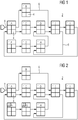
- FIG. 1 shows a function diagram 2 for the configuration of a process control system or an automation system.
- the function diagram 2 is modularly composed of individual function blocks, in short blocks 4, which each represent an automation function.
- Each block 4 is assigned a unique block identifier A, B,..., I, by means of which it can be identified.
- each module 4 has at least one input and one output, wherein the modules 4 are linked together on the signal side by virtue of in-plane component connections 6.
- the entrances are each at the left edge of the the building blocks 4 representing boxes arranged, the outputs on the right edge.
- the connections 6 between the blocks 4 are in FIG. 1 represented by solid lines.
- the direction of the signal flow - in each case from one output of a block 4 to the input of another block 4 - is illustrated by directional arrows.
- the block A is distinguished from the other blocks B,..., I in that, in addition to an in-plane input, it has a cross-planning (external) input 8 which receives its input signal from another function diagram.
- a cross-planning (external) input 8 which receives its input signal from another function diagram.
- process signal-reading inputs could also be provided which represent an interface to the process to be monitored or controlled by the automation system or to the underlying technical system.
- the module F has no input connection, since its input ports, which are not identified here in more detail, are so-called parameterized input ports, in which the respective input signal is predetermined independently of the results or output signals of the other modules 4.
- the output signal of the block F is fixed, this output signal also represents the input signal for the block F downstream block G. Therefore, the block G can be queued in the processing order immediately after the block F. It thus receives the sequence number 2.
- the process is generally continued until no further module can be processed in this way.
- the block H downstream of the block H no order number can be assigned directly because it next to the signal already set (upper) input still has another (lower) input, the input signal of the signal processing of other blocks is dependent.
- the result of the pre-determined direct order determination is in FIG. 2 shown.
- the already assigned sequence numbers are in each case entered in the upper left corner of the blocks 4 representing box.
- a start identifier according to criterion b) is generally allocated to those modules 4 which have a process-signal-reading input.
- the comparison criteria mentioned under point d) have a comparatively low priority and serve only to ensure the reproducibility of the method (determinism).
- the cross-chart input signal is provided at block A by another already processed function chart and thus is uniquely determined according to criterion c)
- the following sorting results F, G, A, H, B, C, D, E, I
- FIG. 3 shown picture.
- the tracking of the signal path is illustrated by dashed lines therein.
- the building block A is followed by C, then D, then E, H and again D. Da the block D has already been encountered, the forward propagation stops at the block H.
- the blocks encountered in the course of the signal tracking are now assigned the following sequence list.
- the blocks F and G are preceded by the processing number already assigned: FGACDEH (L1)
- the blocks arranged in this sequence list L1 can also be assigned a preliminary sequence number. It should be noted that the numbers 1 and 2 have already been assigned in advance to the blocks F and G, so that the numbering now continues at block A with 3. On the other hand, the provisional numbering in the subsequent recursion steps can also change again. It is also possible to dispense with the allocation of preliminary sequence numbers and instead to work with the sequence lists only in the manner described below. In this procedure, the sequence numbers are thus allocated only on the basis of the finally sorted and complete sequence list.
- the tracked signal path is now traced backwards until a block is reached that has another unselected or marked output connection.
- this is the block E with a further output connection to block I.
- This starts the signal tracking in the forward direction, starting from the block E again.
- the tracked signal path is in FIG. 4 again represented by a dashed line. Since the block A achievable by the block I has already been encountered in the course of the method, the forward propagation stops with the block I. Thus, the sequence list L1 obtained in this iteration step has only one list element, namely I.
- the sequence list obtained in the previous round is updated by the new sequence list (In this case, therefore, only the block E) is placed immediately after the block E in the previous sequence list L1, with the positions of the subsequent list elements (in this case by one) moves backwards.
- the updated sequence list therefore looks like this: FGACDEIH (L2)
- FIG. 5 shown image in which all the blocks of the function diagram 2 the finally assigned sequence numbers are entered. Due to the feedback, two cycle delays occur, namely the transition from H to D and from I to A.
- the recursion procedure would start from the beginning according to the original sorting (done in step II of the method) with the next not yet reached component. This would also be the case after a premature termination of the recursion when reaching a block provided with a start identifier, that is, for example in the case of a process signal-reading module.
- some special treatments may still be required as part of the sequence determination of the blocks. For example, in the case of a function plan that is segmented into sub-plans, it can be determined whether a sub-plan of a block provided with a start identifier also inherits this feature for determining the chart order. In particular, process signal-reading modules receive a higher priority by the allocation of a start identifier. In addition, there are internal dependencies for certain blocks, which can also affect the order of processing. For example, in the case of sequencers, there is a higher-level header block that is connected on the output side to further associated sequence blocks on the same function chart.
- header block is always executed before the step blocks, as the subsequently interconnected step blocks depend on the signals generated by the header block. For this reason, such a header module also receives a start identifier, which is not inherited to the associated plan or subplan, since the dependency is effective only within the plan.
Description
Die Erfindung betrifft ein Verfahren zur Bestimmung der Bearbeitungsreihenfolge von Bausteinen eines Funktionsplans für ein sequentiell arbeitendes Automatisierungssystem gemäß dem Oberbegriff des Anspruchs 1. Ein derartiges Verfahren ist beispielsweise aus der
Die Erfindung betrifft weiterhin eine zur Durchführung des Verfahrens geeignete elektronische Datenverarbeitungsanlage. Die Projektierung von leittechnischen Funktionen eines Automatisierungssystems basiert häufig auf graphischen Funktionsplänen, in denen die erforderlichen Automatisierungsfunktionen in Form graphischer Funktionsblöcke platziert, parametriert und miteinander verschaltet werden. Ein derartiger Funktionsplan kann beispielsweise gemäß der Industrienorm IEC 61131-3 gestaltet sein. Die Funktionsblöcke, die auch als Funktionsbausteine oder einfach nur als Bausteine bezeichnet werden, weisen in der Regel einen oder mehrere Eingänge und/oder Ausgänge auf. An den Eingängen werden üblicherweise die Ausgangssignale von anderen, vorgeschalteten Bausteinen des Funktionsplans eingelesen. Neben derartigen "internen" Eingängen gibt es häufig auch noch externe Eingänge, an denen in planübergreifender Weise von Bausteinen eines anderen Funktionsplans bereitgestellte Signale eingelesen werden, sowie solche Eingänge, die zum Einlesen eines unmittelbar aus dem zu überwachenden oder zu steuernden Prozess entnommenen oder ausgelesenen Signals (Prozesssignal) bestimmt sind. Schließlich können auch noch Bausteine mit fest parametrierten Eingangsports vorgesehen sein, welche keine Eingangsverbindung aufweisen. Gemäß dem grundlegenden Prinzip "Eingabe - Verarbeitung - Ausgabe" werden in einem Baustein die Eingangssignale verarbeitet und die resultierenden Ergebnisse an den Ausgängen zur Verfügung gestellt. Da die in den Bausteinen verarbeiteten Signale normalerweise logische Signale und keine physikalischen Größen darstellen, können innerhalb eines Funktionsplans auch isolierte Bausteine oder so genannte Endbausteine ohne Ausgänge existieren. Andere Ausgänge wiederum können externe bzw. planübergreifende Ausgänge des Funktionsplans sein.The invention further relates to an electronic data processing system suitable for carrying out the method. The planning of process control functions of an automation system is often based on graphical function diagrams in which the required automation functions are placed, parameterized and interconnected in the form of graphical function blocks. Such a function diagram can be designed, for example, according to the industry standard IEC 61131-3. The function blocks, which are also referred to as function blocks or simply as blocks, usually have one or more inputs and / or outputs. At the inputs, the output signals from other, upstream blocks of the function diagram are usually read in. In addition to such "internal" inputs, there are often also external inputs to which signals provided by blocks of another function plan are read in across the plan, as well as those inputs which are used for reading in a signal taken or read directly from the process to be monitored or controlled (Process signal) are determined. After all It is also possible to provide blocks with permanently parameterized input ports which have no input connection. According to the fundamental principle "input - processing - output", the input signals are processed in a block and the resulting results are made available at the outputs. Since the signals processed in the blocks normally represent logical signals and not physical quantities, isolated blocks or so-called end blocks without outputs can also exist within a function diagram. Other outputs can be external or cross-chart outputs of the function chart.
Jeder der von einem Funktionsbaustein repräsentierten Automatisierungsfunktionen ist üblicherweise eine entsprechende Software-Routine zugeordnet, die beispielsweise als auf einer Zielplattform ablauffähiger Software-Code in einer Programmbibliothek hinterlegt sein kann oder auch dynamisch in einem Interpreter oder dergleichen erzeugt werden kann. Die Ausführung und Bearbeitung der den einzelnen Bausteinen entsprechenden Programm-Routinen auf der Zielplattform des Automatisierungssystems erfolgt in der Regel sequentiell in einem festen Zeittakt, wobei nach Bearbeitung aller zu einer Ablaufgruppe bzw. zu einem Funktionsplan gehörigen Bausteine die Bearbeitung nach einer bestimmten Wartezeit erneut beginnt. Dabei ist es insbesondere bei größeren Funktionsplänen mit einer großen Anzahl von Bausteinen und Rückkopplungen von Bedeutung, die Bearbeitungsreihenfolge der Bausteine derart zu wählen, dass Zyklusverzögerungen bzw. Tot-Zeiten in den Signalverläufen vermieden oder zumindest minimiert werden. Dadurch soll eine möglichst zeitnahe Reaktion der Automatisierung auf den zugrunde liegenden Prozess gewährleistet sein. Mit einem Zyklusverzug bezeichnet man die Situation, dass ein signalseitig nachverschalteter Baustein vor dem signalerzeugenden Baustein selbst ausgeführt wird und somit das Signal des vorherigen Zyklus am Bausteineingang ansteht und für die interne Berechnung verwendet wird. Ein derartiger Zyklusverzug oder Zyklusversatz, der insbesondere aus einer Rückkopplung von Signalen resultieren kann, führt letztendlich dazu, dass ein für die Bearbeitung einer Funktion erforderliches Signal erst bei der übernächsten Ausführung des Zyklus zur Verfügung steht bzw. dass der Baustein mit einem nicht aktuellen Signal arbeitet, das aus dem vorherigen Zyklus stammt. Hieraus resultiert eine um die Anzahl der Zyklusverzüge verzögerte Reaktion des Systems. Durch eine Erhöhung der Taktrate für die gesamte Verschaltung könnte zwar prinzipiell die Reaktionszeit wieder verkürzt werden, doch ist dies aus wirtschaftlichen Gründen meist nicht tragbar.Each of the automation functions represented by a function module is usually associated with a corresponding software routine which, for example, can be stored in a program library as software code executable on a target platform or can also be generated dynamically in an interpreter or the like. The execution and processing of the individual blocks corresponding program routines on the target platform of the automation system is usually carried out sequentially in a fixed time cycle, after editing all belonging to a runtime group or to a function block blocks processing after a certain waiting time begins again. It is particularly important for larger function plans with a large number of blocks and feedback of importance to select the processing order of the blocks such that cycle delays or dead times in the waveforms are avoided or at least minimized. This should ensure a timely response of automation to the underlying process. A cycle delay refers to the situation that a block connected downstream of the signal is executed before the signal-generating block itself and thus the signal of the previous cycle is present at the block input and is used for the internal calculation. Such a cycle delay or cycle offset, which may result in particular from a feedback of signals, ultimately results in that a signal required for the processing of a function is available only at the next but one execution of the cycle or that the block is operating with a non-current signal, the off comes from the previous cycle. This results in a delayed by the number of cycle delays reaction of the system. By increasing the clock rate for the entire interconnection, in principle, the reaction time could be shortened again, but this is usually not feasible for economic reasons.
Da die gesamte Verschaltung aller Bausteine einer Automatisierungseinheit sehr komplex werden kann, sollte die Ablaufreihenfolge unter der Nebenbedingung, dass die Anzahl der Zyklusverzüge für eine hohe Effizienz der Automatisierung möglichst gering sein sollte, vorzugsweise automatisch ermittelt werden. Ein derartiges Verfahren zur automatischen Ermittlung der Bearbeitungsreihenfolge von Bausteinen eines Funktionsplans für ein sequentiell arbeitendes Automatisierungssystem ist beispielsweise aus der
Ein weiterer Nachteil der bisherigen Lösung macht sich insbesondere dann bemerkbar, falls der Funktionsplan für eine leichtere Nachvollziehbarkeit und Übersichtlichkeit oder aus sonstigen Gründen in mehrere Teilpläne segmentiert ist. Bei dem bereits bekannten Verfahren wird nämlich die Bearbeitungsreihenfolge der Teilpläne bei der Ermittlung der jeweiligen planinternen Bausteinreihenfolge nicht berücksichtigt. Zudem weist dieses Verfahren Performance-Probleme auf und arbeitet nicht streng deterministisch, da Eingänge eines Bausteins in beliebiger Reihenfolge abgefragt werden. Damit kann ein wiederholtes Ausführen des Verfahrens bei identisch verschalteten Funktionsplänen zu unterschiedlichen Ergebnissen führen.Another disadvantage of the previous solution is particularly noticeable if the function plan is segmented for easier traceability and clarity or for other reasons in several sub-plans. Namely, in the already known method, the processing order becomes the sub-plans are not taken into account when determining the respective in-plane block sequence. In addition, this method has performance problems and does not work strictly deterministic, since inputs of a block are queried in any order. Repeated execution of the procedure with identically interconnected function diagrams can lead to different results.
Der Erfindung liegt daher die Aufgabe zugrunde, ein Verfahren der eingangs genannten Art anzugeben, das sich in möglichst universeller und reproduzierbarer Weise auf eine Vielzahl verschiedener Funktionspläne anwenden lässt und dabei die Reaktionszeit eines Automatisierungssystems auf Prozesssignale minimiert. Weiterhin soll eine zur Durchführung des Verfahrens geeignete elektronische Datenverarbeitungsanlage angegeben werden.The invention is therefore based on the object of specifying a method of the type mentioned, which can be applied in as universal and reproducible manner to a variety of different function plans, while minimizing the reaction time of an automation system to process signals. Furthermore, an electronic data processing system suitable for carrying out the method should be specified.
Bezüglich des Verfahrens wird die Aufgabe erfindungsgemäß durch die Merkmale des Anspruchs 1 gelöst.With regard to the method, the object is achieved by the features of
Die Erfindung geht dabei von der Überlegung aus, dass das Verfahren zur Bestimmung der Bearbeitungsreihenfolge für eine möglichst universelle Anwendbarkeit auf eine große Klasse von Funktionsplänen weitgehend unabhängig von Randbedingungen wie z. B. dem Vorhandensein von externen (planübergreifenden) Ausgängen sein sollte. Weiterhin sollte die Bearbeitungsreihenfolge derart gewählt werden, dass bereits eindeutig bestimmte oder von vornherein feststehende Eingangssignale frühzeitig im System verwertet werden. Mit anderen Worten: Insbesondere bei Vorhandensein von Rückkopplungen sollten Bausteine mit bereits definierten Eingangszuständen möglichst früh abgearbeitet und somit mit einer niedrigen Bearbeitungsfolgenummer versehen werden, damit anstehende Prozesssignale frühzeitig in die Automatisierung einfließen und die Reaktionszeit verkürzen.The invention is based on the consideration that the method for determining the processing sequence for as universal applicability to a large class of function plans largely independent of constraints such. B. should be the presence of external (cross-plane) outputs. Furthermore, the processing sequence should be chosen such that already clearly determined or fixed from the outset input signals are utilized early in the system. In other words, especially in the presence of feedback blocks with already defined input states should be processed as early as possible and thus provided with a low processing sequence number so that pending process signals early in the automation flow and shorten the reaction time.
Zu diesem Zweck sollte eine vorwiegend graphisch orientierte Methode zum Einsatz kommen, die im Grundsatz vorwärtsgerichtet ist. Die Vergabe von Bearbeitungsfolgenummern oder Reihenfolgenummern sollte also entscheidend von der Vorwärtspropagation in Signalrichtung im Funktionsplan abhängen, wobei an Verzweigungspunkten, also Bausteinen mit mehreren Ausgängen, eindeutige Verzweigungsregeln zugrunde zu legen sind. Zur Realisierung eindeutiger und reproduzierbarer Propagationsregeln, die im Allgemeinen Verzweigungsregeln und Abbruchbedingungen für die Schrittfolgen in Vorwärts- und in Rückwärtsrichtung umfassen, sollten die Ausgänge der Bausteine jeweils in einer vorgegebenen Weise geordnet sein, wobei die geometrische Lage eines Ausgangs bzw. einer Ausgangsverbindung im Funktionsplan als Ordnungskriterium dienen kann. Zur Erzielung guter Performance-Eigenschaften beim Ablauf der Verfahrensschritte sollte überdies vermieden werden, dass eine Komponente (ein Baustein) mehrfach bearbeitet werden muss. In dieser Hinsicht ist erfindungsgemäß vorgesehen, die Reihenfolgenummern nicht in fortlaufender Reihenfolge zu vergeben, sondern ggf. eine temporär oder vorläufig vergebene Reihenfolge im Sinne eines iterativen Prozesses im Verlauf des Verfahrens auch noch einmal zu verändern und dabei zu verbessern. Derartige Iterationen werden anhand von Listenoperationen vorgenommen, wobei die Listenelemente durch die eindeutigen Bausteinkennungen gegeben sind, und wobei die Reihenfolge der Listenelemente je nach dem gerade durchgeführten Iterations- oder Rekursionsschritt eine vorläufige oder endgültige Bearbeitungsreihenfolge für die Bausteine des Funktionsplans repräsentiert.For this purpose, a predominantly graphically oriented method should be used, which is fundamentally forward-looking. The assignment of processing sequence numbers or sequence numbers should therefore depend decisively on the forward propagation in the signal direction in the function diagram, whereby branching points, that is to say modules with multiple outputs, are to be based on unambiguous branching rules. To realize unique and reproducible propagation rules, which generally include branching rules and termination conditions for the forward and reverse step sequences, the outputs of the blocks should each be ordered in a predetermined manner, with the geometric location of an output in the function diagram Order criterion can serve. To achieve good performance characteristics in the course of the process steps should also be avoided that a component (a block) must be processed multiple times. In this regard, it is provided according to the invention not to assign the sequence numbers in consecutive order, but possibly a temporarily or provisionally assigned order in the sense of an iterative process in the course of Process again to change and improve. Such iterations are made on the basis of list operations, the list elements being given by the unique building block identifiers, and the order of the list elements representing a preliminary or final processing order for the building blocks of the function plan, depending on the iteration or recursion step being performed.
Im Hinblick auf weitere erfindungswesentliche und vorteilhafte Ausgestaltungen des Verfahrens, insbesondere was die Propagationsregeln betrifft, wird auf die Merkmale des Anspruchs 1, auf die Unteransprüche sowie auf das Ausführungsbeispiel verwiesen. Die dabei maßgeblichen Prinzipien lassen sich wie folgt zusammenfassen: Bausteine, bei denen alle Eingangssignale bereits eindeutig definiert sind, können sofort behandelt werden. Ausgangspunkt sind hierbei insbesondere Bausteine, die ausschließliche parametrierte Eingangsports, sprich keine Eingangsverbindungen aufweisen, bzw. Bausteine, bei denen die Quellen aller Eingangsverbindungen in Plänen oder Plansegmenten lokalisiert sind, die aufgrund der Planreihenfolge bereits ausgeführt sind. Derartigen Bausteinen kann bereits vorab eine Reihenfolgenummer in aufsteigender Reihenfolge zugeordnet werden. Anschließend werden die Komponenten (die Bausteine) für die nachfolgende Rekursionsprozedur vorsortiert, wobei sie gemäß einer vorgegebenen Hierarchie von Ordnungs- und Vergleichskriterien nach absteigender Priorität geordnet werden. Schließlich werden die Bausteine in dieser Reihenfolge nacheinander abgearbeitet, wobei rekursiv über die Ausgangsverbindungen alle signalseitig nachgeschalteten Bausteine berücksichtigt werden. Die Signalverfolgung wird so lange fortgesetzt, bis entweder ein bereits verarbeiteter (d. h. im Verlauf der Propagation erreichter) Baustein angetroffen wird oder bis alle Bausteine des Funktionsplans verarbeitet worden sind. Zur besseren "Buchhaltung" über bereits verarbeitete Bausteine und zurückgelegte Pfade ist es vorteilhaft, jeden bereits erreichten Baustein und/oder jede bereits gewählte Ausgangsverbindung zu markieren.With regard to further inventive and advantageous embodiments of the method, in particular as regards the propagation rules, reference is made to the features of
Bei komplexeren Funktionsplänen, die der Übersichtlichkeit halber oder aus anderen Gründen in Teilpläne unterteilt sind, erfolgt die Ermittlung der Bausteinreihenfolge in zwei Phasen. In der ersten Phase wird die Reihenfolge der Teilpläne gemäß dem hier dargestellten Verfahren ermittelt, wobei die einzelnen Teilpläne wie Bausteine und die planübergreifenden Verbindungen analog zu Bausteinverbindungen behandelt werden. Die Gesamtheit der Funktionspläne kann somit wie ein virtueller Funktionsplan betrachtet werden, in dem jeder Plan in Form eines Bausteines repräsentiert ist. In der zweiten Phase wird die Reihenfolge der Bausteine jeweils innerhalb eines Teilplanes ermittelt.For more complex function diagrams, which are subdivided into sub-plans for the sake of clarity or for other reasons, the sequence of components is determined in two phases. In the first phase, the order of the sub-plans is determined according to the method presented here, whereby the individual sub-plans, such as building blocks and the cross-chart connections, are treated analogously to block connections. The totality of the function diagrams can thus be considered as a virtual function diagram in which each plan is represented in the form of a building block. In the second phase, the sequence of the blocks is determined within a subplan.
Vorteilhafterweise wird das Verfahren von einer elektronischen Datenverarbeitungsanlage automatisiert durchgeführt. Dazu ist eine elektronische Datenverarbeitungsanlage mit einer Eingabeeinheit, einer Ausgabeeinheit und einer Verarbeitungseinheit vorgesehen, deren Komponenten für die Durchführung des Verfahrens ausgelegt sind. Vorteilhafterweise ist das Verfahren in einer Speichereinheit der elektronischen Datenverarbeitungsanlage als ausführbares Software-Programm hinterlegt. Als besonders vorteilhaft erweist es sich, wenn das Software-Programm in der Programmiersprache Java implementiert ist, da es auf diese Weise unmittelbar auf einer Vielzahl von Zielplattformen, für die ein Java-Interpreter oder eine so genannte virtuelle Maschine zur Verfügung steht, ablauffähig ist.Advantageously, the method is carried out automatically by an electronic data processing system. For this purpose, an electronic data processing system with an input unit, an output unit and a processing unit is provided, whose components are designed for carrying out the method. Advantageously, the method is stored in a memory unit of the electronic data processing system as an executable software program. It proves to be particularly advantageous if the software program is implemented in the Java programming language, since in this way it can run directly on a plurality of target platforms for which a Java interpreter or a so-called virtual machine is available.
Die mit der Erfindung erzielten Vorteile bestehen insbesondere darin, dass ein Verfahren zur Ermittlung der Bearbeitungsreihenfolge von Bausteinen eines Funktionsplans bereitgestellt wird, mit dem nicht nur eine Minimierung von Zyklusverzügen erreicht wird, sondern bei dem durch die Priorisierung von prozesseinlesenden Bausteinen und von Bausteinen mit bereits festgelegten Eingangssignalen besonders kurze Reaktionszeiten auf Prozesssignale erreicht werden. Da das Verfahren weitestgehend unabhängig von Randbedingungen ist, lässt es sich in universeller Weise auf beliebige Funktionspläne anwenden. Auch bei komplexen Funktionsplänen, die in Teilpläne unterteilt sind, wird insbesondere durch die Berücksichtigung der Planreihenfolge bei der Ermittlung der planinternen Bearbeitungsreihenfolge eine optimierte Signalverarbeitung erreicht.The advantages achieved by the invention are in particular that a method for determining the processing order of blocks of a function plan is provided, with which not only a minimization of cycle delays is achieved, but in the prioritization of process-reading blocks and blocks with already specified input signals particularly short reaction times to process signals can be achieved. Since the process is largely independent of boundary conditions, it can be applied in a universal manner to any function diagrams. Even with complex function plans, which are subdivided into sub-plans, optimized signal processing is achieved, in particular, by taking into account the order of plan when determining the in-plane processing sequence.
Ein Ausführungsbeispiel der Erfindung wird anhand einer Zeichnung näher erläutert. Darin zeigen:
- FIG 1 bis 5
- aufeinander folgende Verfahrensschritte bei der Bestimmung der Bearbeitungsreihenfolge von Bausteinen eines Funktionsplans, wobei die ermittelte Reihenfolge in
FIG 5 eingetragen ist, und - FIG 6
- die für denselben Funktionsplan unter Zugrundelegung alternativer Verzweigungsregeln ermittelte Reihenfolge.
- 1 to 5
- successive process steps in the determination of the processing sequence of blocks of a function plan, wherein the determined sequence in
FIG. 5 is registered, and - FIG. 6
- The order determined for the same function plan using alternative branch rules.
Gleiche Teile sind in allen Figuren mit denselben Bezugszeichen versehen.Identical parts are provided with the same reference numerals in all figures.
Der Baustein A ist gegenüber den anderen Bausteinen B, ..., I insofern ausgezeichnet, als er neben einem planinternen Eingang einen planübergreifenden (externen) Eingang 8 aufweist, der sein Eingangssignal von einem anderen Funktionsplan erhält. Im Allgemeinen könnten auch noch so genannte prozesssignaleinlesende Eingänge vorgesehen sein, die eine Schnittstelle zu dem vom Automatisierungssystem zu überwachenden oder zu steuernden Prozess bzw. zu der zugrundeliegenden technischen Anlage darstellen. Der Baustein F weist keinerlei Eingangsverbindung auf, da seine hier nicht näher kenntlich gemachten Eingangsports so genannte parametrierte Eingangsports sind, bei denen das jeweilige Eingangssignal unabhängig von den Resultaten bzw. Ausgangssignalen der anderen Bausteine 4 vorgegeben ist.The block A is distinguished from the other blocks B,..., I in that, in addition to an in-plane input, it has a cross-planning (external)
Anhand des in
Im ersten Schritt werden alle Bausteine 4 ermittelt und markiert, die keine Eingangsverbindungen aufweisen bzw. bei denen alle Eingangssignale bereits vorhanden sind. Dies betrifft im Allgemeinen auch solche Signale, die von anderen (bereits verarbeiteten) Funktionsplänen ausgehen. Im Ausführungsbeispiel gemäß
Damit ist auch das Ausgangssignal des Bausteins F festgelegt, wobei dieses Ausgangssignal zugleich das Eingangssignal für den dem Baustein F nachgeschalteten Baustein G darstellt. Daher kann der Baustein G in der Bearbeitungsreihenfolge unmittelbar nach dem Baustein F eingereiht werden. Er erhält damit die Reihenfolgenummer 2. Der Vorgang wird im Allgemeinen so lange fortgesetzt, bis kein weiterer Baustein auf diese Weise mehr verarbeitet werden kann. Beispielsweise kann dem dem Baustein G nachgeschalteten Baustein H keine Reihenfolgenummer unmittelbar zugeordnet werden, da er neben dem bereits signalmäßig festgelegten (oberen) Eingang noch einen weiteren (unteren) Eingang aufweist, dessen Eingangssignal von der Signalverarbeitung weiterer Bausteine abhängig ist. Das Resultat der vorab durchgeführten direkten Reihenfolgeermittlung ist in
Im nächsten Schritt werden alle Bausteine 4 bzgl. ihrer nachfolgenden Bearbeitung gewichtet. Die für diese Sortierung verwendeten Kriterien haben maßgeblichen Einfluss auf das Resultat der gesamten Reihenfolgeermittlung. Durch die Veränderung der Ordnungs- und Vergleichskriterien kann das Endergebnis demnach entsprechend modifiziert werden. Eine vorteilhafte Sortierung ergibt sich durch die Anwendung der folgenden Vergleichskriterien, wobei die Priorität der aufgeführten Bedingungen nach unten hin abnimmt. Das heißt: Das Vergleichskriterium b) findet nur dann Anwendung, falls zwei zu vergleichende Bausteine 4 bzgl. dem Vergleichskriterium a) identisch sind, usw.
- a)
Bausteine 4 mit bereits vergebener Reihenfolgenummer - b)
Bausteine 4 mit einer Startkennung - c) Anzahl der eindeutig bestimmten Eingangssignale
- d) eindeutige Bausteinnummer oder Position im Funktionsplan
- a) blocks 4 with already assigned sequence number
- b) blocks 4 with a start identifier
- c) Number of clearly determined input signals
- d) unique block number or position in the function diagram
Eine Startkennung nach Kriterium b) wird im Allgemeinen denjenigen Bausteinen 4 zugeteilt, die einen prozesssignaleinlesenden Eingang aufweisen. Die unter Punkt d) genannten Vergleichskriterien weisen eine vergleichsweise geringe Priorität auf und dienen lediglich dazu, die Reproduzierbarkeit des Verfahrens sicherzustellen (Determinismus). Im Ausführungsbeispiel ergibt sich unter der Voraussetzung, dass das planübergreifende Eingangssignal am Baustein A von einem anderen bereits verarbeiteten Funktionsplan bereitgestellt wird und somit gemäß Kriterium c) eindeutig bestimmt ist, die nachfolgende Sortierung:
F, G, A, H, B, C, D, E, IA start identifier according to criterion b) is generally allocated to those
F, G, A, H, B, C, D, E, I
Gemäß der durch die Vorsortierung erhaltenen Reihenfolge werden nun die einzelnen Bausteine 4 bearbeitet, wobei folgende Fälle zu unterscheiden sind:
- Der betreffende Baustein 4 weist bereits eine Reihenfolgenummer auf. In diesem Fall kann sofort mit
dem nächsten Baustein 4 fortgefahren werden. Im Ausführungsbeispiel trifft dies auf die Bausteine F und G zu. - Andernfalls wird der betreffende Baustein 4 als Startbaustein definiert und der Signalweg unter Beachtung der Verzweigungsregeln in Vorwärtsrichtung verfolgt.
- The
relevant block 4 already has a sequence number. In this case, thenext block 4 can be started immediately. In the exemplary embodiment, this applies to the blocks F and G. - Otherwise, the
relevant block 4 is defined as the start block and the signal path is tracked in the forward direction, taking into account the branching rules.
Beginnend mit Baustein A und unter Zugrundelegung der Regel, dass mehrere Ausgangsverbindungen eines Bausteins der Reihe nach von unten nach oben abgearbeitet werden, ergibt sich das in
F-G-A-C-D-E-H (L1)
Beginning with block A and based on the rule that several output connections of a block are processed sequentially from bottom to top, this results in
FGACDEH (L1)
Den in dieser Sequenzliste L1 angeordneten Bausteinen kann auch eine vorläufige Reihenfolgenummer zugeordnet werden. Dabei ist zum einen zu beachten, dass die Nummern 1 und 2 bereits vorab an die Bausteine F und G vergeben wurden, so dass die Nummerierung nun beim Baustein A mit 3 fortfährt. Zum anderen kann sich die vorläufige Nummerierung in den nachfolgenden Rekursionsschritten auch noch einmal ändern. Es ist auch möglich, auf die Vergabe vorläufiger Reihenfolgenummern zu verzichten und stattdessen nur in der nachfolgend beschriebenen Weise mit den Sequenzlisten zu arbeiten. Bei dieser Vorgehensweise werden die Reihenfolgenummern also erst anhand der endgültig sortierten und vollständigen Sequenzliste zugeteilt.The blocks arranged in this sequence list L1 can also be assigned a preliminary sequence number. It should be noted that the
Der verfolgte Signalpfad wird nun in Rückwärtsrichtung zurückverfolgt, bis ein Baustein erreicht wird, der eine weitere noch nicht ausgewählte oder markierte Ausgangsverbindung aufweist. Im Ausführungsbeispiel ist dies der Baustein E mit einer weiteren Ausgangsverbindung zu Baustein I. Damit startet die Signalverfolgung in Vorwärtsrichtung ausgehend vom Baustein E erneut. Der verfolgte Signalweg ist in
F-G-A-C-D-E-I-H (L2)
The tracked signal path is now traced backwards until a block is reached that has another unselected or marked output connection. In the exemplary embodiment, this is the block E with a further output connection to block I. This starts the signal tracking in the forward direction, starting from the block E again. The tracked signal path is in
FGACDEIH (L2)
Die entsprechend aktualisierte vorläufige Reihenfolge der Bausteine ist wiederum in
Es schließt sich eine weitere Propagationsphase in Rückwärtsrichtung an. Dies stoppt schließlich beim Baustein A, der noch eine zweite, bislang nicht verfolgte Ausgangsverbindung zu Baustein B aufweist. Die anschließende Vorwärtsbewegung endet gemäß
F-G-A-B-C-D-E-I-H (L3)
This is followed by another propagation phase in the backward direction. This finally stops at the block A, which still has a second, so far unfollowed output connection to block B. The subsequent forward movement ends according to
FGABCDEIH (L3)
Da alle Bausteine des Funktionsplans abgearbeitet wurden, stoppt das Verfahren. Abschließend ergibt sich das in
Für den Fall, dass mehrere Ausgangsverbindungen an einem Baustein in entgegengesetzter Richtung von oben nach unten abgearbeitet würden, würde sich das in
Falls nach der vollständigen Abarbeitung aller Ausgänge des Startbausteins weitere, bislang noch nicht erreichte Bausteine existieren würden, so würde die Rekursionsprozedur gemäß der ursprünglichen (in Schritt II. des Verfahrens vorgenommenen) Sortierung mit dem nächsten noch nicht erreichten Baustein von vorne beginnen. Dies wäre auch nach einem vorzeitigen Abbruch der Rekursion beim Erreichen eines mit einer Startkennung versehenen Bausteins, also beispielsweise bei einem prozesssignaleinlesenden Baustein, der Fall.If, after the complete execution of all outputs of the start module, further, as yet not yet achieved, components would exist, then the recursion procedure would start from the beginning according to the original sorting (done in step II of the method) with the next not yet reached component. This would also be the case after a premature termination of the recursion when reaching a block provided with a start identifier, that is, for example in the case of a process signal-reading module.
Insbesondere bei komplexeren Funktionsplänen können im Rahmen der Reihenfolgeermittlung der Bausteine noch einige Sonderbehandlungen erforderlich sein. Beispielsweise kann bei einem Funktionsplan, der in Teilpläne segmentiert ist, festgelegt werden, ob ein Teilplan der einen mit einer Startkennung versehenen Baustein enthält, ebenfalls dieses Merkmal für die Ermittlung der Planreihenfolge erbt. Insbesondere erhalten prozesssignaleinlesende Bausteine durch die Zuteilung einer Startkennung eine höhere Priorität. Darüber hinaus gibt es für bestimmte Bausteine interne Abhängigkeiten, die sich ebenfalls in der Reihenfolge der Bearbeitung auswirken können. So gibt es beispielsweise bei Ablaufketten einen übergeordneten Kopfbaustein, der ausgangsseitig mit weiteren zugehörigen Schrittbausteinen auf demselben Funktionsplan verbunden ist. Dabei ist zu gewährleisten, dass der Kopfbaustein stets vor den Schrittbausteinen ausgeführt wird, da die nachverschalteten Schrittbausteine auf die vom Kopfbaustein generierten Signale angewiesen sind. Aus diesem Grund erhält ein derartiger Kopfbaustein ebenfalls eine Startkennung, die jedoch nicht an den zugehörigen Plan oder Teilplan vererbt wird, da die Abhängigkeit nur planintern wirksam ist.Especially with more complex function diagrams, some special treatments may still be required as part of the sequence determination of the blocks. For example, in the case of a function plan that is segmented into sub-plans, it can be determined whether a sub-plan of a block provided with a start identifier also inherits this feature for determining the chart order. In particular, process signal-reading modules receive a higher priority by the allocation of a start identifier. In addition, there are internal dependencies for certain blocks, which can also affect the order of processing. For example, in the case of sequencers, there is a higher-level header block that is connected on the output side to further associated sequence blocks on the same function chart. It must be ensured that the header block is always executed before the step blocks, as the subsequently interconnected step blocks depend on the signals generated by the header block. For this reason, such a header module also receives a start identifier, which is not inherited to the associated plan or subplan, since the dependency is effective only within the plan.
Schließlich kann es auch noch erforderlich oder sinnvoll sein, die Abarbeitungsreihenfolge für bestimmte Pläne manuell zu beeinflussen, um z. B. unter Rückgriff auf empirisch gewonnenes Know-how die Sequenz der Bausteine vorteilhaft zu modifizieren.Finally, it may also be necessary or useful to manually influence the execution order for certain plans to z. B. Advantageously to modify the sequence of the building blocks by recourse to empirically gained know-how.
Claims (14)
- Method for determining the processing order of modules (4) in a function plan (2) for a sequentially operating automation system,- each module (4) being assigned a module identifier (A, B, C, ..., I) in a reversibly unambiguous manner,- the modules (4) being linked, on the signal side, by means of inputs and outputs, and- in the case of a module (4) having a plurality of outputs, these outputs respectively being organized in a predefined manner,and
the signal path in the function plan (2) being respectively traced in a recursive procedure in the forward direction starting from a starting module and being traced back in the reverse direction,- a predefined set of propagation rules respectively being used as a basis for propagation in the forward direction and propagation in the reverse direction,- the modules (4) which are reached during forward propagation being assigned a sequence list whose list elements comprise the module identifiers (A, B, C, ..., I),- the sequence list available after the previous pass being updated during each pass through the recursion loop using the current sequence list, and- the order of the list elements in the sequence list available after the method has been concluded being used as a representation of the processing order of the modules (4),- the function plan (2) being segmented into partial plans, the order of the partial plans being taken into account when determining the plan-internal processing order of the modules (4),in that the sequence list is updated by inserting the sequence list obtained in the current pass through the recursion loop into the previous sequence list, the insertion being effected immediately after that list element which represents the starting point of the forward propagation carried out last,
in that the propagation path pursued during the previous propagation operations in the forward direction is traced back during reverse propagation and
in that reverse propagation is aborted as soon as the module (4) reached in the current propagation step is the starting module or a module (4) having an output connection which has not yet been traced during the previous recursion loops. - Method according to Claim 1,
characterized in that
when a module (4) having a plurality of outputs is reached during forward propagation, the next possible output which has not yet been traced during the previous recursion loops is selected according to the predefined order of outputs. - Method according to Claim 1 or 2,
characterized in that
forward propagation is aborted as soon as- a module (4) which has already been reached during the method,- a module (4) having a start identifier or an order number which has already been allocated in advance, or- an end module without output connections or with only external outputshas been found in the next propagation step in accordance with the predefined propagation rules. - Method according to one of Claims 1 to 3,
characterized in that
the recursion loop is ended as soon as all modules (4) which can be reached from the starting module (4) have been reached. - Method according to one of Claims 1 to 4,
characterized in that
each module (4) which has already been reached and/or each output connection which has already been selected is/are marked. - Method according to one of Claims 1 to 5,
characterized in that
the list elements in the sequence list are organized in that order which corresponds to the order in which the modules (4) are reached when tracing the signal path in the forward direction. - Method according to one of Claims 1 to 6,
characterized in that
all modules (4) without an input connection and all modules (4) whose input signal has been unambiguously determined are assigned an order number in ascending order in advance. - Method according to one of Claims 1 to 7,
characterized in that
all modules (4) which are intended to read in process signals are assigned a start identifier in advance. - Method according to one of Claims 1 to 8,
characterized in that
the modules (4) are organized according to their priority before the recursive procedure is carried out, an organization hierarchy which comprises the following organization and comparison criteria being used as a basis:a) modules (4) having an order number which has already been allocated,b) modules (4) having a start identifier, andc) number of input signals which have been unambiguously determined. - Method according to Claim 9,
characterized in that
a module (4) having the highest possible priority among the modules (4) having an order number which has not yet been allocated is selected as the starting module for the recursive procedure. - Method according to Claim 9 or 10,
characterized in that
the recursion procedure is repeated until all modules (4) in the function plan (2) have been reached, the modules (4) being successively used as a basis as starting modules in the order of decreasing priority. - Electronic data processing system having an input unit, an output unit and a processing unit, the components of which are configured for carrying out the method according to one of Claims 1 to 11.
- Electronic data processing system according to Claim 12, in which the method is stored in a memory unit in the form of an executable software program.
- Electronic data processing system according to Claim 12 or 13, in which the software program is implemented using the programming language Java.
Applications Claiming Priority (2)
| Application Number | Priority Date | Filing Date | Title |
|---|---|---|---|
| DE102005031246 | 2005-07-01 | ||
| PCT/EP2006/063681 WO2007003573A2 (en) | 2005-07-01 | 2006-06-29 | Method for determination of the processing sequence of a component of a function plan and electronic data processing unit for carrying out said method |
Publications (2)
| Publication Number | Publication Date |
|---|---|
| EP1899773A2 EP1899773A2 (en) | 2008-03-19 |
| EP1899773B1 true EP1899773B1 (en) | 2018-06-27 |
Family
ID=37562233
Family Applications (1)
| Application Number | Title | Priority Date | Filing Date |
|---|---|---|---|
| EP06777508.0A Active EP1899773B1 (en) | 2005-07-01 | 2006-06-29 | Method for determination of the processing sequence of components of a function plan and electronic data processing unit for carrying out said method |
Country Status (3)
| Country | Link |
|---|---|
| US (1) | US8635597B2 (en) |
| EP (1) | EP1899773B1 (en) |
| WO (1) | WO2007003573A2 (en) |
Families Citing this family (4)
| Publication number | Priority date | Publication date | Assignee | Title |
|---|---|---|---|---|
| EP2407839B1 (en) * | 2010-07-14 | 2013-04-17 | Siemens Aktiengesellschaft | Method for structuring a function plan into function plan areas |
| US9274790B2 (en) * | 2014-04-30 | 2016-03-01 | Oracle International Corporation | Customization manager |
| EP3299914A1 (en) * | 2016-09-26 | 2018-03-28 | Siemens Aktiengesellschaft | Method for creating a control flow plan |
| US11521080B2 (en) * | 2019-05-07 | 2022-12-06 | Sap Se | Declarative rule-based decision support system |
Family Cites Families (10)
| Publication number | Priority date | Publication date | Assignee | Title |
|---|---|---|---|---|
| US4451702A (en) * | 1977-12-27 | 1984-05-29 | Stromberg-Carlson Corporation | Arrangement of interactive telephone switching processors for performing timing analyses of port events |
| WO1987003974A1 (en) | 1986-07-07 | 1987-07-02 | Bbc Aktiengesellschaft Brown, Boveri & Cie. | Software tool for automatic production of a logical function diagram |
| DE4230178B4 (en) | 1992-09-09 | 2009-05-20 | Siemens Ag | A method of automatically determining the order of signal processing in a sequential building block system |
| JP3697317B2 (en) * | 1996-05-28 | 2005-09-21 | 株式会社東芝 | Communication device |
| US6233703B1 (en) | 1997-12-31 | 2001-05-15 | Triconex Corporation | Automatic generation of evaluation order for a function block diagram and detection of any associated errors |
| DE10108962A1 (en) | 2001-02-20 | 2002-09-12 | Pilz Gmbh & Co | Method and device for programming a safety controller |
| US7437740B1 (en) * | 2002-11-26 | 2008-10-14 | Unisys Corporation | Generation of Java language application programming interface for an object-oriented data store |
| US7587710B2 (en) | 2003-02-14 | 2009-09-08 | Siemens Aktiengesellschaft | Method for determining the processing sequence of function blocks of an automated system and corresponding automated system |
| CA2433379A1 (en) * | 2003-06-25 | 2004-12-25 | Ibm Canada Limited - Ibm Canada Limitee | Modulo scheduling of multiple instruction chains |
| JP4285307B2 (en) * | 2004-04-02 | 2009-06-24 | 株式会社日立製作所 | Data processing apparatus and method |
-
2006
- 2006-06-29 EP EP06777508.0A patent/EP1899773B1/en active Active
- 2006-06-29 WO PCT/EP2006/063681 patent/WO2007003573A2/en active Application Filing
- 2006-06-29 US US11/922,841 patent/US8635597B2/en active Active
Non-Patent Citations (1)
| Title |
|---|
| None * |
Also Published As
| Publication number | Publication date |
|---|---|
| US8635597B2 (en) | 2014-01-21 |
| US20090216343A1 (en) | 2009-08-27 |
| EP1899773A2 (en) | 2008-03-19 |
| WO2007003573A2 (en) | 2007-01-11 |
| WO2007003573A3 (en) | 2007-03-29 |
Similar Documents
| Publication | Publication Date | Title |
|---|---|---|
| DE1928202B2 (en) | Device for the creation of statistical data on the operational sequence of program-controlled data processing systems | |
| DE2556617C2 (en) | Sliding and rotating circuit | |
| EP1899773B1 (en) | Method for determination of the processing sequence of components of a function plan and electronic data processing unit for carrying out said method | |
| DE102007006421A1 (en) | Method for operating controlled machines | |
| EP2306349A1 (en) | Method for verifying the real-time capability of a system | |
| DE102011107646A1 (en) | Method and system for the dynamic distribution of program functions in distributed control systems | |
| EP2126644B1 (en) | Method for the conversion of ladder diagrams | |
| EP1593007A2 (en) | Method for determining the processing sequence of function blocks of an automated system and corresponding automated system | |
| EP2482148A1 (en) | Method for projecting and/or programming a multi-functional component of an industrial automation assembly | |
| DE3545957A1 (en) | Method and circuit arrangement for automatically processing setting-up functions in numeric controls | |
| WO2008098989A1 (en) | Method for exchanging structural components for an automation system | |
| EP1184760B1 (en) | Method for commanding and or controlling a technical process | |
| EP0006488B1 (en) | A jump-method in a memory-controlled sequential control device for machines, especially for industrial sewing machines, and sequential control circuits therefor | |
| DE102020103349B4 (en) | LOAD BALANCE OF TWO PROCESSORS WHEN EXECUTING DIVERSITY-REDUNDANT INSTRUCTION SEQUENCES | |
| EP0757314A1 (en) | Method for patching software functions in a communications system | |
| DE4230178B4 (en) | A method of automatically determining the order of signal processing in a sequential building block system | |
| DE102021003842A1 (en) | Method for creating a configuration data set for a motor vehicle by means of an electronic computing device and electronic computing device | |
| EP3764218A1 (en) | Method for the computer-assisted interaction of an operator with a model of a technical system | |
| WO2023066624A1 (en) | Data processing network for performing data processing | |
| WO2023131450A1 (en) | Method for optimizing a process | |
| EP1399856A1 (en) | Method for combining distributed data bases | |
| WO1999027448A2 (en) | Program-controlled unit and method | |
| DE102014107072A1 (en) | Method for parallel programming of a plurality of vehicle control devices | |
| DE19824568A1 (en) | Network switching procedures program control method | |
| EP3299956A1 (en) | Method and assembly for updating a computer program |
Legal Events
| Date | Code | Title | Description |
|---|---|---|---|
| PUAI | Public reference made under article 153(3) epc to a published international application that has entered the european phase |
Free format text: ORIGINAL CODE: 0009012 |
|
| 17P | Request for examination filed |
Effective date: 20080102 |
|
| AK | Designated contracting states |
Kind code of ref document: A2 Designated state(s): AT BE BG CH CY CZ DE DK EE ES FI FR GB GR HU IE IS IT LI LT LU LV MC NL PL PT RO SE SI SK TR |
|
| DAX | Request for extension of the european patent (deleted) | ||
| 17Q | First examination report despatched |
Effective date: 20080602 |
|
| DAX | Request for extension of the european patent (deleted) | ||
| RAP1 | Party data changed (applicant data changed or rights of an application transferred) |
Owner name: SIEMENS AKTIENGESELLSCHAFT |
|
| RAP1 | Party data changed (applicant data changed or rights of an application transferred) |
Owner name: SIEMENS AKTIENGESELLSCHAFT |
|
| GRAP | Despatch of communication of intention to grant a patent |
Free format text: ORIGINAL CODE: EPIDOSNIGR1 |
|
| INTG | Intention to grant announced |
Effective date: 20180302 |
|
| GRAS | Grant fee paid |
Free format text: ORIGINAL CODE: EPIDOSNIGR3 |
|
| GRAA | (expected) grant |
Free format text: ORIGINAL CODE: 0009210 |
|
| AK | Designated contracting states |
Kind code of ref document: B1 Designated state(s): AT BE BG CH CY CZ DE DK EE ES FI FR GB GR HU IE IS IT LI LT LU LV MC NL PL PT RO SE SI SK TR |
|
| REG | Reference to a national code |
Ref country code: GB Ref legal event code: FG4D Free format text: NOT ENGLISH |
|
| REG | Reference to a national code |
Ref country code: AT Ref legal event code: REF Ref document number: 1012856 Country of ref document: AT Kind code of ref document: T Effective date: 20180715 |
|
| REG | Reference to a national code |
Ref country code: IE Ref legal event code: FG4D Free format text: LANGUAGE OF EP DOCUMENT: GERMAN |
|
| REG | Reference to a national code |
Ref country code: DE Ref legal event code: R096 Ref document number: 502006015937 Country of ref document: DE |
|
| PG25 | Lapsed in a contracting state [announced via postgrant information from national office to epo] |
Ref country code: LT Free format text: LAPSE BECAUSE OF FAILURE TO SUBMIT A TRANSLATION OF THE DESCRIPTION OR TO PAY THE FEE WITHIN THE PRESCRIBED TIME-LIMIT Effective date: 20180627 Ref country code: FI Free format text: LAPSE BECAUSE OF FAILURE TO SUBMIT A TRANSLATION OF THE DESCRIPTION OR TO PAY THE FEE WITHIN THE PRESCRIBED TIME-LIMIT Effective date: 20180627 Ref country code: BG Free format text: LAPSE BECAUSE OF FAILURE TO SUBMIT A TRANSLATION OF THE DESCRIPTION OR TO PAY THE FEE WITHIN THE PRESCRIBED TIME-LIMIT Effective date: 20180927 Ref country code: SE Free format text: LAPSE BECAUSE OF FAILURE TO SUBMIT A TRANSLATION OF THE DESCRIPTION OR TO PAY THE FEE WITHIN THE PRESCRIBED TIME-LIMIT Effective date: 20180627 |
|
| REG | Reference to a national code |
Ref country code: NL Ref legal event code: MP Effective date: 20180627 |
|
| REG | Reference to a national code |
Ref country code: LT Ref legal event code: MG4D |
|
| PG25 | Lapsed in a contracting state [announced via postgrant information from national office to epo] |
Ref country code: GR Free format text: LAPSE BECAUSE OF FAILURE TO SUBMIT A TRANSLATION OF THE DESCRIPTION OR TO PAY THE FEE WITHIN THE PRESCRIBED TIME-LIMIT Effective date: 20180928 Ref country code: LV Free format text: LAPSE BECAUSE OF FAILURE TO SUBMIT A TRANSLATION OF THE DESCRIPTION OR TO PAY THE FEE WITHIN THE PRESCRIBED TIME-LIMIT Effective date: 20180627 |
|
| PG25 | Lapsed in a contracting state [announced via postgrant information from national office to epo] |
Ref country code: NL Free format text: LAPSE BECAUSE OF FAILURE TO SUBMIT A TRANSLATION OF THE DESCRIPTION OR TO PAY THE FEE WITHIN THE PRESCRIBED TIME-LIMIT Effective date: 20180627 |
|
| PG25 | Lapsed in a contracting state [announced via postgrant information from national office to epo] |
Ref country code: SK Free format text: LAPSE BECAUSE OF FAILURE TO SUBMIT A TRANSLATION OF THE DESCRIPTION OR TO PAY THE FEE WITHIN THE PRESCRIBED TIME-LIMIT Effective date: 20180627 Ref country code: CZ Free format text: LAPSE BECAUSE OF FAILURE TO SUBMIT A TRANSLATION OF THE DESCRIPTION OR TO PAY THE FEE WITHIN THE PRESCRIBED TIME-LIMIT Effective date: 20180627 Ref country code: RO Free format text: LAPSE BECAUSE OF FAILURE TO SUBMIT A TRANSLATION OF THE DESCRIPTION OR TO PAY THE FEE WITHIN THE PRESCRIBED TIME-LIMIT Effective date: 20180627 Ref country code: PL Free format text: LAPSE BECAUSE OF FAILURE TO SUBMIT A TRANSLATION OF THE DESCRIPTION OR TO PAY THE FEE WITHIN THE PRESCRIBED TIME-LIMIT Effective date: 20180627 Ref country code: EE Free format text: LAPSE BECAUSE OF FAILURE TO SUBMIT A TRANSLATION OF THE DESCRIPTION OR TO PAY THE FEE WITHIN THE PRESCRIBED TIME-LIMIT Effective date: 20180627 Ref country code: IS Free format text: LAPSE BECAUSE OF FAILURE TO SUBMIT A TRANSLATION OF THE DESCRIPTION OR TO PAY THE FEE WITHIN THE PRESCRIBED TIME-LIMIT Effective date: 20181027 |
|
| REG | Reference to a national code |
Ref country code: CH Ref legal event code: PL |
|
| PG25 | Lapsed in a contracting state [announced via postgrant information from national office to epo] |
Ref country code: IT Free format text: LAPSE BECAUSE OF FAILURE TO SUBMIT A TRANSLATION OF THE DESCRIPTION OR TO PAY THE FEE WITHIN THE PRESCRIBED TIME-LIMIT Effective date: 20180627 Ref country code: ES Free format text: LAPSE BECAUSE OF FAILURE TO SUBMIT A TRANSLATION OF THE DESCRIPTION OR TO PAY THE FEE WITHIN THE PRESCRIBED TIME-LIMIT Effective date: 20180627 |
|
| REG | Reference to a national code |
Ref country code: BE Ref legal event code: MM Effective date: 20180630 |
|
| REG | Reference to a national code |
Ref country code: DE Ref legal event code: R097 Ref document number: 502006015937 Country of ref document: DE |
|
| PG25 | Lapsed in a contracting state [announced via postgrant information from national office to epo] |
Ref country code: MC Free format text: LAPSE BECAUSE OF FAILURE TO SUBMIT A TRANSLATION OF THE DESCRIPTION OR TO PAY THE FEE WITHIN THE PRESCRIBED TIME-LIMIT Effective date: 20180627 Ref country code: LU Free format text: LAPSE BECAUSE OF NON-PAYMENT OF DUE FEES Effective date: 20180629 |
|
| REG | Reference to a national code |
Ref country code: IE Ref legal event code: MM4A |
|
| PG25 | Lapsed in a contracting state [announced via postgrant information from national office to epo] |
Ref country code: IE Free format text: LAPSE BECAUSE OF NON-PAYMENT OF DUE FEES Effective date: 20180629 Ref country code: CH Free format text: LAPSE BECAUSE OF NON-PAYMENT OF DUE FEES Effective date: 20180630 Ref country code: LI Free format text: LAPSE BECAUSE OF NON-PAYMENT OF DUE FEES Effective date: 20180630 |
|
| PLBE | No opposition filed within time limit |
Free format text: ORIGINAL CODE: 0009261 |
|
| STAA | Information on the status of an ep patent application or granted ep patent |
Free format text: STATUS: NO OPPOSITION FILED WITHIN TIME LIMIT |
|
| PG25 | Lapsed in a contracting state [announced via postgrant information from national office to epo] |
Ref country code: DK Free format text: LAPSE BECAUSE OF FAILURE TO SUBMIT A TRANSLATION OF THE DESCRIPTION OR TO PAY THE FEE WITHIN THE PRESCRIBED TIME-LIMIT Effective date: 20180627 Ref country code: BE Free format text: LAPSE BECAUSE OF NON-PAYMENT OF DUE FEES Effective date: 20180630 |
|
| 26N | No opposition filed |
Effective date: 20190328 |
|
| REG | Reference to a national code |
Ref country code: AT Ref legal event code: MM01 Ref document number: 1012856 Country of ref document: AT Kind code of ref document: T Effective date: 20180629 |
|
| PG25 | Lapsed in a contracting state [announced via postgrant information from national office to epo] |
Ref country code: SI Free format text: LAPSE BECAUSE OF FAILURE TO SUBMIT A TRANSLATION OF THE DESCRIPTION OR TO PAY THE FEE WITHIN THE PRESCRIBED TIME-LIMIT Effective date: 20180627 Ref country code: FR Free format text: LAPSE BECAUSE OF NON-PAYMENT OF DUE FEES Effective date: 20180827 |
|
| PG25 | Lapsed in a contracting state [announced via postgrant information from national office to epo] |
Ref country code: AT Free format text: LAPSE BECAUSE OF NON-PAYMENT OF DUE FEES Effective date: 20180629 |
|
| PG25 | Lapsed in a contracting state [announced via postgrant information from national office to epo] |
Ref country code: TR Free format text: LAPSE BECAUSE OF FAILURE TO SUBMIT A TRANSLATION OF THE DESCRIPTION OR TO PAY THE FEE WITHIN THE PRESCRIBED TIME-LIMIT Effective date: 20180627 |
|
| PG25 | Lapsed in a contracting state [announced via postgrant information from national office to epo] |
Ref country code: HU Free format text: LAPSE BECAUSE OF FAILURE TO SUBMIT A TRANSLATION OF THE DESCRIPTION OR TO PAY THE FEE WITHIN THE PRESCRIBED TIME-LIMIT; INVALID AB INITIO Effective date: 20060629 Ref country code: PT Free format text: LAPSE BECAUSE OF FAILURE TO SUBMIT A TRANSLATION OF THE DESCRIPTION OR TO PAY THE FEE WITHIN THE PRESCRIBED TIME-LIMIT Effective date: 20180627 |
|
| PG25 | Lapsed in a contracting state [announced via postgrant information from national office to epo] |
Ref country code: CY Free format text: LAPSE BECAUSE OF FAILURE TO SUBMIT A TRANSLATION OF THE DESCRIPTION OR TO PAY THE FEE WITHIN THE PRESCRIBED TIME-LIMIT Effective date: 20180627 |
|
| PGFP | Annual fee paid to national office [announced via postgrant information from national office to epo] |
Ref country code: DE Payment date: 20220630 Year of fee payment: 18 |
|
| PGFP | Annual fee paid to national office [announced via postgrant information from national office to epo] |
Ref country code: GB Payment date: 20230710 Year of fee payment: 18 |