EP1898666A2 - Electret condenser microphone - Google Patents
Electret condenser microphone Download PDFInfo
- Publication number
- EP1898666A2 EP1898666A2 EP07291069A EP07291069A EP1898666A2 EP 1898666 A2 EP1898666 A2 EP 1898666A2 EP 07291069 A EP07291069 A EP 07291069A EP 07291069 A EP07291069 A EP 07291069A EP 1898666 A2 EP1898666 A2 EP 1898666A2
- Authority
- EP
- European Patent Office
- Prior art keywords
- rectangular
- condenser microphone
- diaphragm
- box
- metal case
- Prior art date
- Legal status (The legal status is an assumption and is not a legal conclusion. Google has not performed a legal analysis and makes no representation as to the accuracy of the status listed.)
- Withdrawn
Links
Images

Classifications
-
- H—ELECTRICITY
- H04—ELECTRIC COMMUNICATION TECHNIQUE
- H04R—LOUDSPEAKERS, MICROPHONES, GRAMOPHONE PICK-UPS OR LIKE ACOUSTIC ELECTROMECHANICAL TRANSDUCERS; DEAF-AID SETS; PUBLIC ADDRESS SYSTEMS
- H04R19/00—Electrostatic transducers
- H04R19/01—Electrostatic transducers characterised by the use of electrets
- H04R19/016—Electrostatic transducers characterised by the use of electrets for microphones
Landscapes
- Physics & Mathematics (AREA)
- Engineering & Computer Science (AREA)
- Acoustics & Sound (AREA)
- Signal Processing (AREA)
- Electrostatic, Electromagnetic, Magneto- Strictive, And Variable-Resistance Transducers (AREA)
- Condensed Matter Physics & Semiconductors (AREA)
- General Physics & Mathematics (AREA)
- Computer Hardware Design (AREA)
- Microelectronics & Electronic Packaging (AREA)
- Power Engineering (AREA)
- Details Of Audible-Bandwidth Transducers (AREA)
Abstract
Description
- The present invention relates to an electret condenser microphone, and more particularly, to a surface-mount-device (SMD) type electret condenser microphone having a rectangular box shape, which can be easily curled.
- Condenser microphones are widely used in mobile communication terminals, audio equipment, etc. A typical condenser microphone includes a voltage bias element, a diaphragm/backplate pair configured to form a capacitance (C) varying with a sound pressure, and a junction field effect transistor (JFET) configured to buffer an output signal. Such a typical condenser microphone is fabricated by assembling a diaphragm, a spacer ring, an insulating ring, a backplate, a conductive ring, and a printed circuit board (PCB) within a case, and curling an edge portion of the case.
- However, since defects occur during the process of curling the edge portion of the case, sound quality is degraded. Compared with a cylinder-shaped condenser microphone, a rectangular-box-shaped condenser microphone is easy to mount on a main board because it can easily recognize directionality of parts. However, the process of curling an edge portion of a case receiving parts is more difficult in the rectangular-box-shaped case than in the cylinder-shaped case.
- Accordingly, the present invention is directed to an electret condenser microphone that substantially obviates one or more problems due to limitations and disadvantages of the related art.
- An object of the present invention is to provide an SMD-type electret condenser microphone having a rectangular box shape, in which a curling process can be easily performed by chamfering an edge of a rectangular-box-shaped case, and sound leakage caused by the chamfer can be prevented by using a sealing pad.
- Additional advantages, objects, and features of the invention will be set forth in part in the description which follows and in part will become apparent to those having ordinary skill in the art upon examination of the following or may be learned from practice of the invention. The objectives and other advantages of the invention may be realized and attained by the structure particularly pointed out in the written description and claims hereof as well as the appended drawings.
- To achieve these objects and other advantages and in accordance with the purpose of the invention, as embodied and broadly described herein, there is provided a rectangular-box-shaped electret condenser microphone, including: a pair of a diaphragm and a backplate disposed to face each other, with a spacer being interposed therebetween; å conductive base for electrically conducting the diaphragm; an insulating base for electrically insulating the backplate and the conductive base; a polar ring for electrically conducting the diaphragm; a metal case having a rectangular box shape with one side open, such that the diaphragm, the backplate, the conductive base, the insulating base, and the polar ring are received, the metal case including a curling surface, an edge portion of which is chamfered; a printed circuit board on which circuit components are mounted, the printed circuit board including a conductive pattern and a protruding connection terminal; and a sealing pad mounted on the insulating base to seal a gap between the metal case and the printed circuit board.
- The sealing pad may have a rectangular ring shape and may be formed of a flexible material, for example, rubber and resin. The curling surface of the case may be used as a connection terminal. The rectangular-box-shaped electret condenser microphone may further include a sound hole in a printed circuit board or a bottom surface of the case so as to receive an external sound.
- It is to be understood that both the foregoing general description and the following detailed description of the present invention are exemplary and explanatory and are intended to provide further explanation of the invention as claimed.
- The accompanying drawings, which are included to provide a further understanding of the invention and are incorporated in and constitute a part of this application, illustrate embodiment(s) of the invention and together with the description serve to explain the principle of the invention. In the drawings:
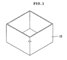
- FIG. 1 is a perspective view of a case of a conventional rectangular-box-shaped condenser microphone;
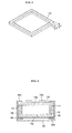
- FIG. 2 is a perspective view of a case of a rectangular-box-shaped condenser microphone according to an embodiment of the present invention;
- FIG. 3 is a perspective view illustrating an assembled state of a rectangular-box-shaped condenser microphone according to an embodiment of the present invention;
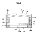
- FIG. 4 is a side sectional view of the rectangular-box-shaped condenser microphone illustrated in FIG. 3;
- FIG. 5 is a perspective view of a sealing pad according to an embodiment of the present invention; and
- FIG. 6 is a side sectional view of a rectangular-box-shaped condenser microphone according to another embodiment of the present invention.
- Reference will now be made in detail to the preferred embodiments of the present invention, examples of which are illustrated in the accompanying drawings. Wherever possible, the same reference numbers will be used throughout the drawings to refer to the same or like parts.
- FIG. 2 is a perspective view of a case of a rectangular-box-shaped condenser microphone according to an embodiment of the present invention, FIG. 3 is a perspective view illustrating an assembled state of a rectangular-box-shaped condenser microphone according to an embodiment of the present invention, and FIG. 4 is a side sectional view of the rectangular-box-shaped condenser microphone illustrated in FIG. 3.
- Referring to FIGs. 2 to 4, the rectangular-box-shaped condenser microphone includes a
metal case 102, apolar ring 104a, adiaphragm 104, aspacer 106, aninsulating base 108, abackplate 110 with asound hole 110a, aconductive base 112, a rectangular-ring-shaped sealing pad 114, and a printed circuit board (PCB) 116. Themetal case 102 has a rectangular box shape with one side open, such that parts are received therein. In the rectangular-box-shaped metal case 102, edge portions ofcurling surfaces 102c are chamfered for the purpose of easy curling. Thepolar ring 104a and thediaphragm 104 are built in themetal case 102. The rectangular-ring-shaped sealing pad 114 is used for preventing sound leakage. A conductive pattern and a protrudingconnection terminal 116a are formed in thePCB 116. - Referring to FIG. 2, the
metal case 102 has a rectangular box shape with one side open, and fouredges 102b of the open side are chamfered. Therefore, during the curling process, theend portions 102 of the adjacent surfaces do not overlap each other. Thesound hole 102a is formed in the bottom surface of the case. Thesound hole 102a may be formed in the PCB 116, instead of thecase 102, depending on a sound entry structure of the condenser microphone. - The
diaphragm 104 and thebackplate 110 are disposed to face each other, with theinsulating spacer 106 being interposed therebetween. Thediaphragm 104 can be vibrated by external sound. Thediaphragm 104 is electrically connected to thePCB 116 through thepolar ring 104a and themetal case 102. Thebackplate 110 and theconductive base 112 are electrically isolated from themetal case 102 by theinsulating base 108. Since such a structure has been well known to those skilled in the art, further description will be omitted. - Referring to FIG. 5, the rectangular-ring-
shaped sealing pad 114 prevents sound of the condenser microphone from leaking out. The sealingpad 114 is formed of a flexible material, for example, rubber and resin. Thesealing pad 114 is mounted into themetal case 102 and then the PCB 116 is put into themetal case 102. Thereafter, when themetal case 102 is curled, thesealing pad 114 is pressed to seal the gap between themetal case 102 and the PCB 116. When thesealing pad 114 is pressed by the curling process, its height is reduced from t1 to t2. - As illustrated in FIG. 3, the condenser microphone assembled in the above-mentioned way can be easily curled because the
edge portions 102c of the adjacent surfaces of thecase 102 do not overlap one another. Theprotruding connection terminal 116a makes it easy to perform an SMD process. Two or more connection terminals may be formed in the PCB 116. Thecurling surface 102c of thecase 102 may be used as a ground terminal. - FIG. 6 is a side sectional view of a rectangular-box-shaped condenser microphone according to another embodiment of the present invention.
- Referring to FIG. 6, the rectangular-box-shaped condenser microphone includes a
metal case 102, apolar ring 104a, adiaphragm 104, aspacer 106, aninsulating base 108, abackplate 110 with asound hole 110a, aconductive base 112, a rectangular-ring-shaped sealing pad 114, and a PCB 116. Themetal case 102 has a rectangular box shape with one side open, such that parts are received therein. In the rectangular-box-shaped metal case 102,edge portions 102b ofcurling surfaces 102c are chamfered for the purpose of easy curling. Thepolar ring 104a and thediaphragm 104 are built in themetal case 102. The rectangular-ring-shaped sealing pad 114 is used for preventing sound leakage. A conductive pattern, a protrudingconnection terminal 116a, and asound hole 116b are formed in thePCB 116. - A significant difference between the two condenser microphones is that the condenser microphone of FIG. 6 has the
sound hole 116b in the PCB 116, while the condenser microphone of FIG. 4 has thesound hole 102a in thecase 102. Further description about other elements will be omitted for avoiding the duplication. - As described above, the electret condenser microphone according to the embodiments of the present invention can be easily curled by chamfering the edge portions of the rectangular-box-shaped case. Furthermore, sound characteristics of the electret condenser microphone can be improved by sealing the gap between the case and the PCB using the sealing pad.
- It will be apparent to those skilled in the art that various modifications and variations can be made in the present invention. Thus, it is intended that the present invention covers the modifications and variations of this invention provided they come within the scope of the appended claims and their equivalents.
Claims (4)
- A rectangular-box-shaped electret condenser microphone, comprising:a pair of a diaphragm and a backplate disposed to face each other, with a spacer being interposed therebetween;a conductive base for electrically conducting the diaphragm;an insulating base for electrically insulating the backplate and the conductive base;a polar ring for electrically conducting the diaphragm;a metal case having a rectangular box shape with one side open, such that the diaphragm, the backplate, the conductive base, the insulating base, and the polar ring are received, the metal case including a curling surface, an edge portion of which is chamfered;a printed circuit board on which circuit components are mounted, the printed circuit board including a conductive pattern and a protruding connection terminal; anda sealing pad mounted on the insulating base to seal a gap between the metal case and the printed circuit board.
- The rectangular-box-shaped electret condenser microphone of claim 1, wherein the sealing pad has a rectangular ring shape and is formed of a flexible material, including rubber and resin.
- The rectangular-box-shaped electret condenser microphone of claim 1, wherein the curling surface of the case is used as a connection terminal.
- The rectangular-box-shaped electret condenser microphone of claim 1, further comprising a sound hole in a printed circuit board or a bottom surface of the case so as to receive an external sound.
Applications Claiming Priority (1)
| Application Number | Priority Date | Filing Date | Title |
|---|---|---|---|
| KR1020060085180A KR100797440B1 (en) | 2006-09-05 | 2006-09-05 | Electret condenser microphone |
Publications (2)
| Publication Number | Publication Date |
|---|---|
| EP1898666A2 true EP1898666A2 (en) | 2008-03-12 |
| EP1898666A3 EP1898666A3 (en) | 2012-04-18 |
Family
ID=38786591
Family Applications (1)
| Application Number | Title | Priority Date | Filing Date |
|---|---|---|---|
| EP07291069A Withdrawn EP1898666A3 (en) | 2006-09-05 | 2007-09-05 | Electret condenser microphone |
Country Status (9)
| Country | Link |
|---|---|
| US (1) | US20080056523A1 (en) |
| EP (1) | EP1898666A3 (en) |
| JP (1) | JP4800276B2 (en) |
| KR (1) | KR100797440B1 (en) |
| CN (1) | CN101141833B (en) |
| MY (1) | MY141669A (en) |
| SG (1) | SG140534A1 (en) |
| TW (1) | TWI331880B (en) |
| WO (1) | WO2008029973A1 (en) |
Cited By (2)
| Publication number | Priority date | Publication date | Assignee | Title |
|---|---|---|---|---|
| EP2051539A1 (en) * | 2007-10-18 | 2009-04-22 | BSE Co., Ltd. | MEMS microphone package |
| EP2056620A1 (en) * | 2007-11-02 | 2009-05-06 | BSE Co., Ltd. | MEMS microphone package having sound hole in PCB |
Families Citing this family (5)
| Publication number | Priority date | Publication date | Assignee | Title |
|---|---|---|---|---|
| KR20090039376A (en) * | 2007-10-18 | 2009-04-22 | 주식회사 비에스이 | Stray capacitance reduced condenser microphone |
| KR101109102B1 (en) * | 2010-01-18 | 2012-01-31 | 주식회사 비에스이 | Mems microphone package |
| KR101241475B1 (en) | 2011-11-24 | 2013-03-11 | 이오스 재팬, 인코포레이티드 | Condenser microphone which can be conveniently assembled |
| CN105578370A (en) * | 2016-03-15 | 2016-05-11 | 深圳捷力泰科技开发有限公司 | Electret microphone |
| CN108156564A (en) * | 2018-02-28 | 2018-06-12 | 深圳捷力泰科技开发有限公司 | Electret microphone |
Citations (2)
| Publication number | Priority date | Publication date | Assignee | Title |
|---|---|---|---|---|
| US20050185811A1 (en) * | 2004-02-24 | 2005-08-25 | Chung Dam Song | Parallelepiped condenser microphone |
| WO2006085707A1 (en) * | 2005-02-14 | 2006-08-17 | Bse Co., Ltd. | Case of condenser microphone having ventilation slit |
Family Cites Families (20)
| Publication number | Priority date | Publication date | Assignee | Title |
|---|---|---|---|---|
| US4380041A (en) * | 1978-09-25 | 1983-04-12 | Motorola Inc. | Capacitor pressure transducer with housing |
| JP2739543B2 (en) * | 1993-07-23 | 1998-04-15 | 株式会社ピーエフユー | Electronic device outer case |
| JP3192100B2 (en) * | 1996-11-08 | 2001-07-23 | 株式会社オーディオテクニカ | Microphone |
| JP2000050393A (en) * | 1998-05-25 | 2000-02-18 | Hosiden Corp | Electret condenser microphone |
| JP3425599B2 (en) * | 1999-06-18 | 2003-07-14 | Smk株式会社 | Condenser microphone |
| JP2002374598A (en) * | 2001-06-13 | 2002-12-26 | Hosiden Corp | Condenser microphone |
| JP4697763B2 (en) * | 2001-07-31 | 2011-06-08 | パナソニック株式会社 | Condenser microphone |
| US7184563B2 (en) * | 2003-03-04 | 2007-02-27 | Knowles Electronics Llc. | Electret condenser microphone |
| JP4095927B2 (en) * | 2003-05-15 | 2008-06-04 | 株式会社オーディオテクニカ | Condenser microphone unit |
| KR200330089Y1 (en) * | 2003-07-29 | 2003-10-11 | 주식회사 비에스이 | Integrated base and electret condenser microphone using the same |
| US7136500B2 (en) * | 2003-08-05 | 2006-11-14 | Knowles Electronics, Llc. | Electret condenser microphone |
| KR100549188B1 (en) * | 2003-08-14 | 2006-02-10 | 주식회사 비에스이 | Integrated base and electret condenser microphone using the same |
| JP4272017B2 (en) * | 2003-09-04 | 2009-06-03 | スター精密株式会社 | Manufacturing method of electret condenser microphone |
| KR100544277B1 (en) * | 2003-10-20 | 2006-01-23 | 주식회사 비에스이 | Case making a stair and electret condenser microphone using the same |
| KR100675026B1 (en) * | 2003-11-05 | 2007-01-29 | 주식회사 비에스이 | Method of mounting a condenser microphone on main PCB |
| KR100531716B1 (en) * | 2003-12-04 | 2005-11-30 | 주식회사 비에스이 | Biased Condenser Microphone For SMD |
| KR100544283B1 (en) * | 2004-01-20 | 2006-01-24 | 주식회사 비에스이 | A parallelepiped type condenser microphone for SMD |
| KR100540711B1 (en) * | 2004-01-29 | 2006-01-11 | 주식회사 비에스이 | PDE And Uni-Directional Condenser Microphone using the same |
| KR100544279B1 (en) * | 2004-02-27 | 2006-01-23 | 주식회사 비에스이 | A parallelepiped type directional condenser microphone for SMD |
| JP4150407B2 (en) * | 2005-06-20 | 2008-09-17 | ホシデン株式会社 | Electroacoustic transducer |
-
2006
- 2006-09-05 KR KR1020060085180A patent/KR100797440B1/en not_active IP Right Cessation
- 2006-12-29 WO PCT/KR2006/005860 patent/WO2008029973A1/en active Application Filing
- 2006-12-29 MY MYPI20081621A patent/MY141669A/en unknown
-
2007
- 2007-02-27 CN CN2007100787996A patent/CN101141833B/en not_active Expired - Fee Related
- 2007-03-03 TW TW096107406A patent/TWI331880B/en not_active IP Right Cessation
- 2007-08-02 SG SG200705651-8A patent/SG140534A1/en unknown
- 2007-09-03 JP JP2007228004A patent/JP4800276B2/en not_active Expired - Fee Related
- 2007-09-04 US US11/899,057 patent/US20080056523A1/en not_active Abandoned
- 2007-09-05 EP EP07291069A patent/EP1898666A3/en not_active Withdrawn
Patent Citations (2)
| Publication number | Priority date | Publication date | Assignee | Title |
|---|---|---|---|---|
| US20050185811A1 (en) * | 2004-02-24 | 2005-08-25 | Chung Dam Song | Parallelepiped condenser microphone |
| WO2006085707A1 (en) * | 2005-02-14 | 2006-08-17 | Bse Co., Ltd. | Case of condenser microphone having ventilation slit |
Cited By (2)
| Publication number | Priority date | Publication date | Assignee | Title |
|---|---|---|---|---|
| EP2051539A1 (en) * | 2007-10-18 | 2009-04-22 | BSE Co., Ltd. | MEMS microphone package |
| EP2056620A1 (en) * | 2007-11-02 | 2009-05-06 | BSE Co., Ltd. | MEMS microphone package having sound hole in PCB |
Also Published As
| Publication number | Publication date |
|---|---|
| JP4800276B2 (en) | 2011-10-26 |
| US20080056523A1 (en) | 2008-03-06 |
| TWI331880B (en) | 2010-10-11 |
| EP1898666A3 (en) | 2012-04-18 |
| KR100797440B1 (en) | 2008-01-23 |
| WO2008029973A1 (en) | 2008-03-13 |
| CN101141833A (en) | 2008-03-12 |
| JP2008067384A (en) | 2008-03-21 |
| CN101141833B (en) | 2012-05-30 |
| SG140534A1 (en) | 2008-03-28 |
| MY141669A (en) | 2010-05-31 |
| TW200814831A (en) | 2008-03-16 |
Similar Documents
| Publication | Publication Date | Title |
|---|---|---|
| US7260230B2 (en) | High performance microphone and manufacturing method thereof | |
| EP1898666A2 (en) | Electret condenser microphone | |
| JP4150407B2 (en) | Electroacoustic transducer | |
| US7327851B2 (en) | Parallelepiped condenser microphone | |
| US8107650B2 (en) | Piezoelectric electroacoustic transducing device | |
| US20080063232A1 (en) | Silicon condenser microphone | |
| US8144898B2 (en) | High performance microphone and manufacturing method thereof | |
| US9788093B2 (en) | Audio transducer electrical connectivity | |
| US7629730B2 (en) | Piezoelectric electroacoustic transducing device | |
| US20100290662A1 (en) | Stray capacitance reduced condenser microphone | |
| US7344405B2 (en) | Electro-acoustic transducer with holder | |
| WO2009005211A1 (en) | Diaphragm with air groove and condenser microphone using the same | |
| US20020051547A1 (en) | Capacitor microphone | |
| KR20130062569A (en) | Microphone assembly having ear set function and method of making the same | |
| CN101161031B (en) | Electret condenser microphone and manufacturing method thereof | |
| KR100797438B1 (en) | Microphone without curling process and method of assemblying the microphone | |
| EP1725071A2 (en) | Condenser microphone with air ventilation system | |
| KR100437681B1 (en) | Directional microphone | |
| KR20060091399A (en) | Case of condenser microphone having ventilation slit | |
| KR100722685B1 (en) | Condenser microphone using the elastic and conductive base ring | |
| CN209017308U (en) | Loudspeaker and electronic equipment | |
| US10939192B2 (en) | Electret condenser microphone and manufacturing method thereof | |
| JPS5830399Y2 (en) | condenser microphone | |
| KR20020092627A (en) | Microphone including printed circuit board having protrusion portion for electrical contact and Method of connecting for it to outer apparatus | |
| CN109348384A (en) | Loudspeaker and electronic equipment |
Legal Events
| Date | Code | Title | Description |
|---|---|---|---|
| PUAI | Public reference made under article 153(3) epc to a published international application that has entered the european phase |
Free format text: ORIGINAL CODE: 0009012 |
|
| 17P | Request for examination filed |
Effective date: 20070921 |
|
| AK | Designated contracting states |
Kind code of ref document: A2 Designated state(s): AT BE BG CH CY CZ DE DK EE ES FI FR GB GR HU IE IS IT LI LT LU LV MC MT NL PL PT RO SE SI SK TR |
|
| AX | Request for extension of the european patent |
Extension state: AL BA HR MK YU |
|
| PUAL | Search report despatched |
Free format text: ORIGINAL CODE: 0009013 |
|
| AK | Designated contracting states |
Kind code of ref document: A3 Designated state(s): AT BE BG CH CY CZ DE DK EE ES FI FR GB GR HU IE IS IT LI LT LU LV MC MT NL PL PT RO SE SI SK TR |
|
| AX | Request for extension of the european patent |
Extension state: AL BA HR MK RS |
|
| RIC1 | Information provided on ipc code assigned before grant |
Ipc: H04R 19/01 20060101AFI20120314BHEP |
|
| AKX | Designation fees paid |
Designated state(s): AT BE BG CH CY CZ DE DK EE ES FI FR GB GR HU IE IS IT LI LT LU LV MC MT NL PL PT RO SE SI SK TR |
|
| 17Q | First examination report despatched |
Effective date: 20130221 |
|
| STAA | Information on the status of an ep patent application or granted ep patent |
Free format text: STATUS: THE APPLICATION IS DEEMED TO BE WITHDRAWN |
|
| 18D | Application deemed to be withdrawn |
Effective date: 20150623 |