EP1897761A2 - Motor vehicle with a roll-over bar assembly - Google Patents
Motor vehicle with a roll-over bar assembly Download PDFInfo
- Publication number
- EP1897761A2 EP1897761A2 EP07015435A EP07015435A EP1897761A2 EP 1897761 A2 EP1897761 A2 EP 1897761A2 EP 07015435 A EP07015435 A EP 07015435A EP 07015435 A EP07015435 A EP 07015435A EP 1897761 A2 EP1897761 A2 EP 1897761A2
- Authority
- EP
- European Patent Office
- Prior art keywords
- connecting element
- roll bar
- motor vehicle
- vehicle
- vehicle according
- Prior art date
- Legal status (The legal status is an assumption and is not a legal conclusion. Google has not performed a legal analysis and makes no representation as to the accuracy of the status listed.)
- Withdrawn
Links
Images

Classifications
-
- B—PERFORMING OPERATIONS; TRANSPORTING
- B60—VEHICLES IN GENERAL
- B60R—VEHICLES, VEHICLE FITTINGS, OR VEHICLE PARTS, NOT OTHERWISE PROVIDED FOR
- B60R21/00—Arrangements or fittings on vehicles for protecting or preventing injuries to occupants or pedestrians in case of accidents or other traffic risks
- B60R21/02—Occupant safety arrangements or fittings, e.g. crash pads
- B60R21/13—Roll-over protection
-
- B—PERFORMING OPERATIONS; TRANSPORTING
- B62—LAND VEHICLES FOR TRAVELLING OTHERWISE THAN ON RAILS
- B62D—MOTOR VEHICLES; TRAILERS
- B62D25/00—Superstructure or monocoque structure sub-units; Parts or details thereof not otherwise provided for
- B62D25/08—Front or rear portions
- B62D25/087—Luggage compartments
Definitions
- the present invention relates to a motor vehicle with a roll bar arrangement, which comprises at least one roll bar, a transverse strut and a connecting element with a receiving opening, in which one end of the roll bar is received. Furthermore, the present invention relates to a connecting element for a roll bar arrangement in the motor vehicle.
- Known roll bar assemblies in motor vehicles usually comprise a substantially horizontal and arranged parallel to the transverse axis of the vehicle transverse strut and two mostly U-shaped roll bar.
- the roll bars are in this case attached to the vehicle center end facing the cross member and connected with its second end, which extends to the vehicle outside, via connecting means with the vehicle body.
- the transverse strut is preferably also fastened by means of this connecting device on the vehicle body.
- the European Patent Application EP 1 547 874 A1 describes a roll bar assembly in which the ends of the roll bars, which face the vehicle exterior, extend well down the plane of the crossbar. These extended ends of the roll bar enforce the crossbar and are bolted to it. At this screw connection are tabs attached, which connect the cross-strut roll bar attachment node with a fastener, which in turn is attached to the side body inner wall. In addition, the downwardly extended ends of the roll bars are bolted to a horizontally extending body wall and also connected in the region between the cross member and the horizontal body wall via a tab to the body outer wall. In this roll bar assembly, the consisting of a forming part fastening element on the body outer wall on an extension, are attached to the bolts and other fasteners for storage of the top.
- the object of the present invention is to provide a motor vehicle with an improved roll bar arrangement, which in particular increases the strength of the vehicle body.
- the connecting elements each comprise one Receiving opening, in which both an end of a roll bar and one end of the cross brace are received.
- the cross strut can be made for example from a conventional tubular semi-finished product, as a formed part or preferably as an extruded profile.
- Advantageous in a common storage of the ends of the crossbar and roll bar is the integration of the two elements in a common power flow, which ensures that forces acting on one of the two elements from the outside, can also be absorbed by the other element, creating a significantly increased vehicle stiffness is achieved.
- the receiving opening in the connecting element is preferably designed to be open towards the top and in the direction of the vehicle center.
- the receiving opening is in each case open in the direction of the male elements, the ends of the roll bar and the cross member.
- the receiving opening is closed.
- introduced forces are absorbed practically within the connecting element.
- no critical forces in the vertical direction from the vehicle floor lead the way, which require a positive connection in this direction.
- Due to the mirror-image arrangement of the roll bar arrangement according to the invention the forces which act horizontally along the vehicle transverse axis in the direction of the vehicle center are introduced on the opposite side of the vehicle into the vehicle body.
- the one end of the roll bar and the cross bar are preferably designed so that they are received by the receiving opening of the connecting element substantially positive fit and advantageously as a unit.
- Such a design simplifies the installation of the roll bar arrangement in the motor vehicle and enables a force flow-oriented initiation of occurring forces via contact surfaces in the connecting element.
- detachable fasteners This facilitates assembly and in particular allows easier subsequent replacement of damaged components.
- non-detachable fasteners can be provided. These advantageously reduce the number of assembly steps and the components required in this case, reduce the weight of the assembly and increase the strength of the connection.
- the ends of the roll bars which are preferably tubular, serve as deformation elements which absorb, for example, transverse forces occurring in a side impact. Due to the additional enclosure of the ends of the roll bar through the receiving opening, which additionally acts stiffening, a further destruction of energy is possible. Due to the closed design of the receiving opening in the direction of the vehicle longitudinal axis, relatively high forces, which are introduced obliquely to or in the direction of the vehicle longitudinal axis, can be absorbed by the connecting element.
- the connecting element is supported in a further preferred embodiment of an outer and an inner body wall of the vehicle.
- the inner body wall according to the present body structure, be arranged substantially vertically and / or substantially horizontally.
- it may be the roof of an engine compartment.
- connection of the connecting element on both the outer and on an inner body wall a particularly rigid and solid connection is achieved in the introduced into the connecting element forces, in particular vertical forces, can be advantageously introduced into the vehicle body. On the one hand, this can be enhanced by the double connection enlarged connection area.
- the connections to the outer and inner body panels can be oriented differently and thus optimally accommodate differently directed forces. If, for example, the inner body wall is substantially horizontal, the connecting element can be supported in the vertical direction on it, so that the connection with the outer body wall, which is usually substantially vertical, absorbs only low shear forces. Also, a train in the horizontal vehicle longitudinal direction, as occurs for example when opening a hood hinged to the connecting element, is advantageously absorbed via the connection with a substantially horizontal inner body wall and reduces occurring in the outer body wall shear forces.
- connection of the connecting element to these two body walls according to the invention can be carried out in each case both detachable and insoluble.
- fasteners such as screws, rivets, bolts or snap connections are used for releasable connections, for non-detachable connections preferably joining techniques such as welding, soldering, gluing or permanent forming processes.
- the connecting element can be supported on a horizontal body wall, for example in the case of a vehicle rollover. Even on substantially vertical body walls, the connecting element may be supported on protrusions which are preferably integrated in these walls and which improve the force introduction.
- top bearing in the connecting element.
- both the lateral forces introduced into the top bearing can be taken up as well as the very high tensile forces acting there when opening and closing and forwarded to the vehicle body.
- the connecting element is preferably designed as welded, forged or deformed constructions.
- it is particularly preferred to produce the connecting element as a casting since castings have a very high mechanical strength and thereby provide the design advantages required for such fasteners.
- the integrated into the roll bar assembly connecting elements based on both an inner and on an outer body wall.
- the integrated top storage in the motor vehicle directs the transmitted over the hood on the vehicle forces as well as forces from the Gurtumlenkhebel optimized in the vehicle body and thus increases the safety of the vehicle occupants.
- a vehicle roof is, apart from the locking on the windshield, only connected to the top storage firmly connected to the vehicle. Therefore, it is particularly advantageous lateral forces, which act on the hood, which can be relatively high even at low wind speeds, from the soft top bearings in the roll bar assembly.
- the integration of the top storage in the roll bar assembly of the motor vehicle according to the invention enables a simplified assembly of the top storage and the top of the top storage.
- this particularly preferred embodiment is characterized by a significant improvement in the ease of assembly of all components of the roll bar assembly. This applies both with regard to the inclusion of the ends of roll bar and cross member in the connecting element, as well as with respect to the force-transmitting attachment of the connecting element to the vehicle body, which preferably takes place at least partially form-fitting, especially in the area of inner body panels.
- the resulting elimination of additional required fasteners proves advantageous for the vehicle weight and also for the cost of installation of the vehicle. This not only eliminates the cost of the fasteners but the cost of installing this in the vehicle.
- Particularly advantageous is the flow of force within the roll bar assembly according to the particularly preferred embodiment and the transmission of introduced forces in the vehicle body.
- the reduced space requirement of the roll bar arrangement in the vehicle due to the simple and effective design.
- the optimized power flow between the elements of the roll bar arrangement should be emphasized.
- the resilience of the vehicle safety, in particular the rollover safety, as well as the vehicle stiffness, in particular the transverse stiffness, essential roll bar or crossbar connection significantly improved.
- the roll bar assembly of the motor vehicle according to the invention further avoids any interruption of the power flow or strength-reducing Force curves, which reduces the absorption capacity introduced forces in known systems due to a separate storage of the crossbar and the roll bar.
- Another advantage of the vehicle according to the invention is the integration of the roll bar arrangement, which is arranged directly behind the backrests of the vehicle occupants, as an additional transverse reinforcement in the safety concept of open vehicles. Due to the lack of B-pillar of these vehicles, these have in the area behind the vehicle doors on a reduced transverse stiffness, which is significantly improved by the use of the roll bar assembly.
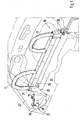
- Fig. 1 shows a three-dimensional view of the roll bar assembly 10 according to the invention, which is shown installed in a motor vehicle.
- the roll bar assembly 10 includes two U-shaped roll bar 11, a cross member 12 and a Connecting element 20 with a receiving opening 21.
- This receiving opening 21 one end of a roll bar 11 and one end of the transverse strut 12 is received in each case.
- the connecting elements 20, which are arranged on both sides between the transverse strut and the inner wall of the body, are executed in mirror image.
- the connecting element 20 is attached to the outer body wall 23.
- the connecting element 20 is on the one hand form-fitting, but additionally fastened by means of a screw 28 on the outer body wall.
- the connecting element 20 is supported horizontally over the contact surface 25 and additionally vertically over the contact surface 26 from. In the embodiment shown, no further fastening elements are attached to the contact surfaces 25 and 26.
- the ends of the roll bars 11, which face the vehicle longitudinal center axis, are suitably fixed in or on the transverse strut.
- the ends of the roll bars, which point in the direction of the outer body walls, are received in the receiving opening 21 of the connecting element 20, which is shown in FIG.
- Fig. 3 shows a section through the connecting element 20 along the section line III - III in Fig. 2 through the receiving opening 21 and the ends located therein of the roll bar 11 and the cross member 12.
- the cross member 12 can be in this exemplary arrangement at a load in the longitudinal direction (transverse to the vehicle longitudinal axis) over the end of the roll bar 11 in the connecting element and thus on the outer body walls 23 are supported.
- the transverse stability of the tubular end of the roll bar 11, which is additionally embraced by the receiving opening is used.
- these are directly or partially over transferred the end of the roll bar 11 in the connecting element and thus to the vehicle body.
- Very high introduced forces lead to the deformation of the cross section of the roll bar 11, wherein the receiving opening 21 of the connecting element 20 also undergoes a deformation.
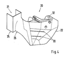
- Fig. 4 shows the connecting element 20 seen from the rear of the vehicle in the direction of the vehicle front.
- integrated in the connecting element hood 30 can be seen, on which the hood is hinged.
- Transverse forces introduced into the convertible top and, in particular, the tensile forces occurring when opening and closing the moving vehicle are picked up by the top bearing 30 and introduced into the vehicle body via the connecting element 20 and via its contact surfaces 22, 25 and 26.
- a Gurtumlenkhebel 32 which also initiates high forces in the vehicle body in the event of an impact, shown.
Abstract
Description
Die vorliegende Erfindung betrifft ein Kraftfahrzeug mit einer Überrollbügelanordnung, welche wenigstens einen Überrollbügel, eine Querstrebe und ein Verbindungselement mit einer Aufnahmeöffnung umfasst, in der ein Ende des Überrollbügels aufgenommen ist. Ferner betrifft die vorliegende Erfindung ein Verbindungselement für eine Überrollbügelanordnung im Kraftfahrzeug.The present invention relates to a motor vehicle with a roll bar arrangement, which comprises at least one roll bar, a transverse strut and a connecting element with a receiving opening, in which one end of the roll bar is received. Furthermore, the present invention relates to a connecting element for a roll bar arrangement in the motor vehicle.
Bekannte Überrollbügelanordnungen in Kraftfahrzeugen umfassen üblicherweise eine im Wesentlichen horizontale und parallel zur Fahrtzeugquerachse angeordnete Querstrebe sowie zwei meist U-förmige Überrollbügel. Die Überrollbügel sind hierbei mit dem der Fahrzeugmitte zugewandten Ende an der Querstrebe befestigt und mit ihrem zweiten Ende, welches sich zur Fahrzeugaußenseite hin erstreckt, über Verbindungseinrichtungen mit der Fahrzeugkarosserie verbunden. Die Querstrebe ist bevorzugt ebenfalls mittels dieser Verbindungseinrichtung am Fahrzeugaufbau befestigt.Known roll bar assemblies in motor vehicles usually comprise a substantially horizontal and arranged parallel to the transverse axis of the vehicle transverse strut and two mostly U-shaped roll bar. The roll bars are in this case attached to the vehicle center end facing the cross member and connected with its second end, which extends to the vehicle outside, via connecting means with the vehicle body. The transverse strut is preferably also fastened by means of this connecting device on the vehicle body.
Für solche Überrollbügelanordnungen sind verschiedene Ausführungsformen bekannt. So beschreibt beispielsweise das
Die
Der Kraftfluss zwischen den Elementen der Überrollbügelanordnung ist bei diesen bekannten Systemen häufig nicht so geführt, dass eine optimale Belastbarkeit der für die Fahrzeugsicherheit wesentlichen Anbindung der Überrollbügelanordnung an den Fahrzeugaufbau erreicht wird. Dies beeinträchtigt ferner die Festigkeit des Fahrzeugaufbaus.The power flow between the elements of the roll bar assembly is often not performed in these known systems, that an optimal load capacity of essential for vehicle safety connection of the roll bar assembly is achieved to the vehicle body. This also affects the strength of the vehicle body.
Weiterhin ist es beispielsweise aus der
Die vorliegende Erfindung stellt sich die Aufgabe, ein Kraftfahrzeug mit einer verbesserten Überrollbügelanordnung zur Verfügung zu stellen, welche insbesondere die Festigkeit des Fahrzeugaufbaus erhöht.The object of the present invention is to provide a motor vehicle with an improved roll bar arrangement, which in particular increases the strength of the vehicle body.
Diese Aufgabe wird erfindungsgemäß durch den Gegenstand des Anspruchs 1 bzw. des Anspruchs 4 gelöst. Vorteilhafte Weiterbildungen sind Gegenstand der Unteransprüche.This object is achieved by the subject matter of claim 1 and of
Bei einem Kraftfahrzeug mit Überrollbügelanordnung nach einer Ausführung der vorliegenden Erfindung umfassen die Verbindungselemente jeweils eine Aufnahmeöffnung, in welcher sowohl ein Ende eines Überrollbügels als auch ein Ende der Querstrebe aufgenommen werden. Die Querstrebe kann dabei beispielsweise aus einem üblichen rohrförmigen Halbzeug, als Umformteil oder vorzugsweise als Strangpressprofil hergestellt sein. Vorteilig bei einer gemeinsamen Lagerung der Enden von Querstrebe und Überrollbügel ist die Einbindung der beiden Elemente in einen gemeinsamen Kraftfluss, wodurch erreicht wird, dass Kräfte, welche von außen auf eines der beiden Elemente wirken, auch vom jeweils anderen Element aufgenommen werden können, wodurch eine deutlich erhöhte Fahrzeugsteifigkeit erzielt wird.In a roll bar type motor vehicle according to an embodiment of the present invention, the connecting elements each comprise one Receiving opening, in which both an end of a roll bar and one end of the cross brace are received. The cross strut can be made for example from a conventional tubular semi-finished product, as a formed part or preferably as an extruded profile. Advantageous in a common storage of the ends of the crossbar and roll bar is the integration of the two elements in a common power flow, which ensures that forces acting on one of the two elements from the outside, can also be absorbed by the other element, creating a significantly increased vehicle stiffness is achieved.
Die Aufnahmeöffnung im Verbindungselement ist dabei bevorzugt nach oben und in Richtung zur Fahrzeugmitte hin offen gestaltet. Damit ist die Aufnahmeöffnung jeweils in Richtung der aufzunehmenden Elemente, der Enden des Überrollbügels sowie der Querstrebe hin geöffnet. In Richtung zur Fahrzeugseite und zum Fahrzeugboden hin ist die Aufnahmeöffnung geschlossen. Damit werden eingeleitete Kräfte praktisch innerhalb des Verbindungselements aufgenommen. Im Fahrbetrieb und im Falle eines Aufpralls treten keine kritischen Kräfte in senkrechter Richtung vom Fahrzeugboden wegweisend auf, die einen Formschluss in dieser Richtung erfordern. Aufgrund der spiegelbildlichen Anordnung der erfindungsgemäßen Überrollbügelanordnung werden die Kräfte, welche horizontal entlang der Fahrzeugquerachse in Richtung zur Fahrzeugmitte hin wirken, auf der gegenüberliegenden Fahrzeugseite in den Fahrzeugaufbau eingeleitet.The receiving opening in the connecting element is preferably designed to be open towards the top and in the direction of the vehicle center. Thus, the receiving opening is in each case open in the direction of the male elements, the ends of the roll bar and the cross member. Towards the vehicle side and the vehicle floor, the receiving opening is closed. Thus, introduced forces are absorbed practically within the connecting element. When driving and in the event of an impact, no critical forces in the vertical direction from the vehicle floor lead the way, which require a positive connection in this direction. Due to the mirror-image arrangement of the roll bar arrangement according to the invention, the forces which act horizontally along the vehicle transverse axis in the direction of the vehicle center are introduced on the opposite side of the vehicle into the vehicle body.
Das eine Ende des Überrollbügels sowie das der Querstrebe sind dabei bevorzugt so ausgeführt, dass sie von der Aufnahmeöffnung des Verbindungselements im Wesentlichen formschlüssig und vorteilhafterweise als eine Einheit aufgenommen werden. Eine solche Gestaltung vereinfacht die Montage der Überrollbügelanordnung im Kraftfahrzeug und ermöglicht eine kraftflussgerechte Einleitung auftretender Kräfte über Kontaktflächen in das Verbindungselement. Auch die Übertragung von Kräften zwischen den Enden des Überrollbügels sowie der Querstrebe erfolgt über eine Abstützung an Bauteilkanten bzw. - flächen.The one end of the roll bar and the cross bar are preferably designed so that they are received by the receiving opening of the connecting element substantially positive fit and advantageously as a unit. Such a design simplifies the installation of the roll bar arrangement in the motor vehicle and enables a force flow-oriented initiation of occurring forces via contact surfaces in the connecting element. The transmission of forces between the ends of the roll bar and the cross member via a support to component edges or - surfaces.
Zur Sicherung der Elemente in der Aufnahmeöffnung ist es auch möglich, lösbare Befestigungen vorzusehen. Dies erleichtert die Montage und ermöglicht insbesondere einen einfacheren nachträglichen Austausch beschädigter Bauteile. Gleichermaßen können auch unlösbare Befestigungen vorgesehen sein. Diese verringern vorteilhaft die Zahl der Montageschritte und der hierbei benötigten Bauteile, verringern das Gewicht der Anordnung und erhöhen die Festigkeit der Verbindung. Durch die Anordnung (von einer Fahrzeugseite zur anderen Fahrzeugseite) Verbindungselement - Überrollbügelende - Querstrebe - Überrollbügelende - Verbindungselement entsteht so in Fahrzeugquerrichtung eine sehr steife Anordnung, welche, als Strukturbauteil im Rohbau montiert, die Rohbausteifigkeit deutlich erhöht. Dabei dienen die Enden der Überrollbügel, welche bevorzugt rohrförmig sind, als Deformationselemente, welche beispielsweise bei einem Seitenaufprall auftretende Querkräfte aufnehmen. Aufgrund der zusätzlichen Einfassung der Enden der Überrollbügel durch die Aufnahmeöffnung, welche zusätzlich versteifend wirkt, ist eine weitere Vernichtung von Energie möglich. Durch die geschlossene Gestaltung der Aufnahmeöffnung in Richtung der Fahrzeuglängsachse, können vom Verbindungselement auch relativ hohe Kräfte, welche schräg zur oder in Richtung der Fahrzeuglängsachse eingeleitet werden, aufgenommen werden.To secure the elements in the receiving opening, it is also possible to provide detachable fasteners. This facilitates assembly and in particular allows easier subsequent replacement of damaged components. Similarly, non-detachable fasteners can be provided. These advantageously reduce the number of assembly steps and the components required in this case, reduce the weight of the assembly and increase the strength of the connection. By arranging (from one side of the vehicle to the other side of the vehicle) connecting element - roll bar end - cross strut - roll bar end - connecting element is formed in the vehicle transverse direction a very rigid arrangement, which, mounted as a structural component in the shell, significantly increases the Rohbausteifigkeit. The ends of the roll bars, which are preferably tubular, serve as deformation elements which absorb, for example, transverse forces occurring in a side impact. Due to the additional enclosure of the ends of the roll bar through the receiving opening, which additionally acts stiffening, a further destruction of energy is possible. Due to the closed design of the receiving opening in the direction of the vehicle longitudinal axis, relatively high forces, which are introduced obliquely to or in the direction of the vehicle longitudinal axis, can be absorbed by the connecting element.
Auch die Kräfte, die über einen Überrollbügel eingeleitet werden, werden von dieser kompakten, von Karosseriewand zu Karosseriewand reichenden, Überrollbügelanordnung gegenüber bekannten Überrollbügelanordnungen verbessert aufgenommen. Vertikale Kräfte auf den Überrollbügel werden dabei direkt von dem bevorzugt flächig in der Aufnahmeöffnung aufgenommenen Überrolibügelquerschnitt auf das Verbindungselement und somit in den Fahrzeugaufbau übertragen. Schräg auf den Überrollbügel aufgebrachte Kräfte werden in Abhängigkeit der Kraftrichtung sowohl von der Querstrebe als auch vom Verbindungselement aufgenommen und in den Fahrzeugaufbau eingeleitet.The forces that are introduced via a roll bar, are improved by this compact, ranging from body wall to body wall, roll bar assembly compared to known roll bar assemblies recorded. Vertical forces on the roll bar are transmitted directly from the preferably areally received in the receiving opening Überrolibügelquerschnitt on the connecting element and thus in the vehicle body. Obliquely applied to the roll bar forces are absorbed as a function of the direction of both the cross member and the connecting element and introduced into the vehicle body.
Aufgrund des vereinfachten Aufbaus und des damit fehlenden Erfordernisses für kraftübertragende Befestigungselemente kann die Montage, die großteils bevorzugt durch Steckverbindung der einzelnen Elemente der Überrollbügelanordnung erfolgt, sehr vereinfacht durchgeführt werden.Due to the simplified structure and the lack of need for force-transmitting fasteners assembly, which largely preferred by plug connection of the individual elements of the roll bar arrangement is carried out very simplified.
Zur Lösung der beschriebenen Aufgabenstellung ist es vorteilhaft, wenn sich das Verbindungselement in einer weiteren bevorzugten Ausführungsform an einer äußeren und einer inneren Karosseriewand des Fahrzeugs abstützt. Dabei kann die innere Karosseriewand, entsprechend dem vorliegenden Karosserieaufbau, im Wesentlichen vertikal und/ oder im Wesentlichen horizontal angeordnet sein. Insbesondere kann es sich um das Dach eines Motorraums handeln.To solve the described problem, it is advantageous if the connecting element is supported in a further preferred embodiment of an outer and an inner body wall of the vehicle. In this case, the inner body wall, according to the present body structure, be arranged substantially vertically and / or substantially horizontally. In particular, it may be the roof of an engine compartment.
Durch die Anbindung des Verbindungselements sowohl an der äußeren als auch an einer inneren Karosseriewand wird eine besonders steife und feste Verbindung erreicht, in der in das Verbindungselement eingeleitete Kräfte, insbesondere Vertikalkräfte, vorteilhaft in die Fahrzeugkarosserie eingeleitet werden können. Hierzu kann einerseits die durch die doppelte Anbindung vergrößerte Verbindungsfläche beitragen. Gleichermaßen können die Verbindungen mit der äußeren und inneren Karosseriewand unterschiedlich orientiert sein und so optimal verschieden gerichtete Kräfte aufnehmen. Sofern beispielsweise die innere Karosseriewand im Wesentlichen horizontal ist, kann sich das Verbindungselement in vertikaler Richtung auf ihr abstützen, so dass die Verbindung mit der äußeren Karosseriewand, die meist im Wesentlichen vertikal ist, nur geringe Schubkräfte aufnimmt. Auch ein Zug in horizontaler Fahrzeuglängsrichtung, wie er beispielsweise beim Öffnen eines am Verbindungselement angelenkten Verdecks auftritt, wird vorteilhaft über die Verbindung mit einer im Wesentlichen horizontalen inneren Karosseriewand aufgenommen und verringert in der äußeren Karosseriewand auftretende Schubkräfte.The connection of the connecting element on both the outer and on an inner body wall a particularly rigid and solid connection is achieved in the introduced into the connecting element forces, in particular vertical forces, can be advantageously introduced into the vehicle body. On the one hand, this can be enhanced by the double connection enlarged connection area. Likewise, the connections to the outer and inner body panels can be oriented differently and thus optimally accommodate differently directed forces. If, for example, the inner body wall is substantially horizontal, the connecting element can be supported in the vertical direction on it, so that the connection with the outer body wall, which is usually substantially vertical, absorbs only low shear forces. Also, a train in the horizontal vehicle longitudinal direction, as occurs for example when opening a hood hinged to the connecting element, is advantageously absorbed via the connection with a substantially horizontal inner body wall and reduces occurring in the outer body wall shear forces.
Die Anbringung des Verbindungselements an diesen zwei Karosseriewänden kann erfindungsgemäß jeweils sowohl lösbar als auch unlösbar ausgeführt sein. Dabei werden für lösbare Verbindungen bevorzugt Befestigungselemente wie Schrauben, Nieten, Bolzen oder Schnappverbindungen eingesetzt, für unlösbare Verbindungen vorzugsweise Verbindungstechniken wie Schweißen, Löten, Kleben oder unlösbare Umformverfahren.The attachment of the connecting element to these two body walls according to the invention can be carried out in each case both detachable and insoluble. In this case, preferably fasteners such as screws, rivets, bolts or snap connections are used for releasable connections, for non-detachable connections preferably joining techniques such as welding, soldering, gluing or permanent forming processes.
Besonders bevorzugt wird ein Großteil der vom Verbindungselement über die Karosseriewände in den Fahrzeugaufbau eingebrachten Kräfte formschlüssig übertragen. Dabei ist es besonders vorteilhaft, wenn sich das Verbindungselement auf einer horizontalen Karosseriewand abstützen kann, beispielsweise im Fall eines Fahrzeugüberschlags. Auch an im Wesentlichen vertikalen Karosseriewänden kann sich das Verbindungselement an bevorzugt in diesen Wänden integrierten, die Krafteinleitung verbessernden, Vorsprüngen abstützen.Particularly preferably, a large part of the forces introduced by the connecting element via the body walls into the vehicle body are transmitted in a form-fitting manner. It is particularly advantageous if the connecting element can be supported on a horizontal body wall, for example in the case of a vehicle rollover. Even on substantially vertical body walls, the connecting element may be supported on protrusions which are preferably integrated in these walls and which improve the force introduction.
Besonders vorteilhaft ist es ebenfalls, das Verdecklager in das Verbindungselement zu integrieren. Durch die beschriebene verbesserte Kraftübertragung vom Verbindungselement auf die Karosseriewände als auch in die Überrollbügelanordnung können sowohl die ins Verdecklager eingeleiteten Querkräfte als insbesondere auch die beim Öffnen und Schließen sehr hohen dort angreifenden Zugkräfte aufgenommen und in den Fahrzeugaufbau weitergeleitet werden.It is also particularly advantageous to integrate the top bearing in the connecting element. By the described improved power transmission from the connecting element to the body walls as well as in the roll bar arrangement, both the lateral forces introduced into the top bearing can be taken up as well as the very high tensile forces acting there when opening and closing and forwarded to the vehicle body.
Vorzugsweise ist es aufgrund der vorher genannten Gründe ebenso zweckmäßig, einen in diesem Bereich der Fahrzeugkarosserie angeordneten Gurtumlenkhebel ebenfalls am Verbindungselement anzuordnen. Gerade für den Insassenschutz ist die optimierte Krafteinleitung vom Gurtumlenkhebel über das Verbindungselement in den Fahrzeugaufbau, welche durch die im erfindungsgemäßen Kraftfahrzeug angeordnete Überrollbügelanordnung zur Verfügung gestellt wird, äußerst vorteilhaft.Preferably, due to the aforementioned reasons, it is likewise expedient to likewise arrange a belt reversing lever arranged in this region of the vehicle body on the connecting element. Especially for occupant protection, the optimized introduction of force from Gurtumlenkhebel via the connecting element in the vehicle body, which is provided by the arranged in the motor vehicle roll bar assembly according to the invention is extremely advantageous.
Um die vielfältigen Anforderungen, welche die vorbeschriebenen Aufgaben und Ausgestaltungen an das Verbindungselement stellen zu erfüllen, ist das Verbindungselement vorzugsweise als Schweiß-, Schmiede- oder Umformkonstruktionen ausgeführt. Besonders bevorzugt ist es jedoch, das Verbindungselement als Gussteil herzustellen, da Gussteile eine sehr hohe mechanische Festigkeit aufweisen und dabei die für solche Verbindungselemente erforderlichen gestalterischen Vorteile bieten.In order to meet the diverse demands which the above-described objects and embodiments make on the connecting element, the connecting element is preferably designed as welded, forged or deformed constructions. However, it is particularly preferred to produce the connecting element as a casting, since castings have a very high mechanical strength and thereby provide the design advantages required for such fasteners.
In einer besonders bevorzugten Ausführungsform stützen sich die in die Uberrollbügelanordnung integrierten Verbindungselemente sowohl an einer inneren als auch an einer äußeren Karosseriewand ab. Dadurch ergänzen sich die vorstehend genannten erfindungsgemäßen Vorteile, wodurch eine im Vergleich zum bisher bekannten Stand der Technik ein deutlich verbessertes Kraftfahrzeug mit Überrollbügelanordnung geschaffen wird.In a particularly preferred embodiment, the integrated into the roll bar assembly connecting elements based on both an inner and on an outer body wall. As a result, the abovementioned advantages according to the invention complement one another, as a result of which a significantly improved motor vehicle with roll bar arrangement is created in comparison with the previously known prior art.
Besonders vorteilhaft an dieser Ausführungsform des erfindungsgemäßen Kraftfahrzeugs mit Überrollbügelanordnung ist eine verbesserte Aufnahme, Weiterleitung in den Fahrzeugaufbau und erforderlichenfalls sogar Vernichtung von Kräften, welche einerseits über die Überrollbügel oder andererseits, wie beispielsweise bei einem Seitenaufprall, über die gegenüberliegende Fahrzeugseite in den Fahrzeugaufbau eingeleitet werden. Die erfindungsgemäße Überrollbügelanordnung, welche im Fahrzeug direkt hinter den Rückenlehnen der Fahrzeuginsassen integriert sein kann, bietet damit eine deutlich erhöhte Querversteifung offener Fahrzeuge.Particularly advantageous in this embodiment of the motor vehicle according to the invention with roll bar arrangement is an improved recording, forwarding in the vehicle body and, if necessary, even destruction of forces which are introduced on the one hand on the roll bar or on the other hand, such as in a side impact on the opposite side of the vehicle in the vehicle body. The roll bar arrangement according to the invention, which can be integrated in the vehicle directly behind the backrests of the vehicle occupants, thus offers a significantly increased transverse reinforcement of open vehicles.
Die integrierte Verdecklagerung im erfindungsgemäßen Kraftfahrzeug leitet die über das Verdeck auf das Fahrzeug übertragenen Kräfte ebenso, wie Kräfte aus dem Gurtumlenkhebel optimiert in den Fahrzeugaufbau ein und erhöht damit die Sicherheit der Fahrzeuginsassen.The integrated top storage in the motor vehicle according to the invention directs the transmitted over the hood on the vehicle forces as well as forces from the Gurtumlenkhebel optimized in the vehicle body and thus increases the safety of the vehicle occupants.
Ein Fahrzeugverdeck ist, abgesehen von der Verriegelung an der Windschutzscheibe, nur an der Verdecklagerung fest mit dem Fahrzeug verbunden. Daher ist es besonders vorteilhaft, Querkräfte, welche das Verdeck wirken, die schon bei geringen Seitenwindgeschwindigkeiten relativ hoch sein können, von den Verdecklagerstellen im Bereich der Überrollbügelanordnung aufzunehmen. Durch die Integration der Verdecklagerung in den Kraftfluss der Überrollbügelanordnung werden folglich vorhandene Potenziale zur Stabilisierung des Verdecklagers ausgeschöpft.A vehicle roof is, apart from the locking on the windshield, only connected to the top storage firmly connected to the vehicle. Therefore, it is particularly advantageous lateral forces, which act on the hood, which can be relatively high even at low wind speeds, from the soft top bearings in the roll bar assembly. By integrating the top storage in the power flow of the roll bar assembly thus existing potentials for stabilizing the top bearing are exhausted.
Die höchsten Kräfte werden jedoch beim Öffnen und Schließen des Verdecks während der Fahrt eingeleitet in das Verdecklager. Aufgrund der großen im Fahrtwind stehenden Fläche wirken dabei sehr hohe Zugkräfte an der Verdecklagerung. Weiterhin ermöglicht die Integration der Verdecklagerung in die Überrollbügelanordnung des erfindungsgemäßen Kraftfahrzeugs eine vereinfachte Montage der Verdecklagerung sowie des Verdecks am Verdecklager.However, the highest forces are introduced when opening and closing the roof while driving in the top storage. Due to the large standing in the wind surface very high tensile forces act on the top storage. Furthermore, the integration of the top storage in the roll bar assembly of the motor vehicle according to the invention enables a simplified assembly of the top storage and the top of the top storage.
Auch insgesamt zeichnet sich diese besonders bevorzugte Ausführungsform durch eine deutliche Verbesserung der Montagefreundlichkeit aller Komponenten der Überrollbügelanordnung aus. Dies gilt sowohl in Hinblick auf die Aufnahme der Enden von Überrollbügel und Querstrebe im Verbindungselement, als auch bezüglich der kraftübertragenden Befestigung des Verbindungselements an der Fahrzeugkarosserie, welche vorzugsweise vor allem im Bereich innerer Karosseriewände zumindest teilweise formschlüssig erfolgt. Der hieraus folgende Wegfall zusätzlich erforderlicher Befestigungselemente erweist sich vorteilig für das Fahrzeuggewicht und ebenfalls für die Montagekosten des Fahrzeugs. Dabei entfallen nicht nur die Kosten für die Befestigungselemente sondern die Kosten für einen Einbau dieser in das Fahrzeug. Besonders vorteilhaft erweist sich der Kraftfluss innerhalb der Überrollbügelanordnung gemäß der besonders bevorzugten Ausführungsform und die Übertragung von eingeleiteten Kräften in den Fahrzeugaufbau. Als weiterer Vorteil der besonders bevorzugten Ausführungsform ist der aufgrund der einfachen und wirkungsvollen Gestaltung verminderte Platzbedarf der Überrollbügelanordnung im Fahrzeug anzuführen.Also, overall, this particularly preferred embodiment is characterized by a significant improvement in the ease of assembly of all components of the roll bar assembly. This applies both with regard to the inclusion of the ends of roll bar and cross member in the connecting element, as well as with respect to the force-transmitting attachment of the connecting element to the vehicle body, which preferably takes place at least partially form-fitting, especially in the area of inner body panels. The resulting elimination of additional required fasteners proves advantageous for the vehicle weight and also for the cost of installation of the vehicle. This not only eliminates the cost of the fasteners but the cost of installing this in the vehicle. Particularly advantageous is the flow of force within the roll bar assembly according to the particularly preferred embodiment and the transmission of introduced forces in the vehicle body. As a further advantage of the particularly preferred embodiment, the reduced space requirement of the roll bar arrangement in the vehicle due to the simple and effective design.
Als besonderer Vorteil des erfindungsgemäßen Kraftfahrzeugs ist der optimierte Kraftfluss zwischen den Elementen der Überrollbügelanordnung hervorzuheben.
Hierdurch wird die Belastbarkeit der für die Fahrzeugsicherheit, insbesondere die Überschlagsicherheit, wie auch für die Fahrzeugsteifigkeit, insbesondere die Quersteifigkeit, wesentlichen Überrollbügel- bzw. Querstrebenanbindung erheblich verbessert. Die Überrollbügelanordnung des erfindungsgemäßen Kraftfahrzeugs vermeidet ferner jegliche Unterbrechung des Kraftflusses oder festigkeitsvermindernde Kraftverläufe, welche bei bekannten Systemen aufgrund einer getrennten Lagerung der Querstrebe und des Überrollbügels die Aufnahmefähigkeit eingeleiteter Kräfte reduziert.As a particular advantage of the motor vehicle according to the invention, the optimized power flow between the elements of the roll bar arrangement should be emphasized.
As a result, the resilience of the vehicle safety, in particular the rollover safety, as well as the vehicle stiffness, in particular the transverse stiffness, essential roll bar or crossbar connection significantly improved. The roll bar assembly of the motor vehicle according to the invention further avoids any interruption of the power flow or strength-reducing Force curves, which reduces the absorption capacity introduced forces in known systems due to a separate storage of the crossbar and the roll bar.
Ein weiterer Vorteil des erfindungsgemäßen Fahrzeugs ist die Integration der Überrollbügelanordnung, welche direkt hinter den Rückenlehnen der Fahrzeuginsassen angeordnet ist, als zusätzliche Querversteifung in das Sicherheitskonzept offener Fahrzeuge. Aufgrund der fehlenden B-Säule dieser Fahrzeuge weisen diese in dem Bereich hinter den Fahrzeugtüren eine verminderte Quersteifigkeit auf, welche durch den Einsatz der Überrollbügelanordnung deutlich verbessert wird.Another advantage of the vehicle according to the invention is the integration of the roll bar arrangement, which is arranged directly behind the backrests of the vehicle occupants, as an additional transverse reinforcement in the safety concept of open vehicles. Due to the lack of B-pillar of these vehicles, these have in the area behind the vehicle doors on a reduced transverse stiffness, which is significantly improved by the use of the roll bar assembly.
Weitere Vorteile, Merkmale und Anwendungsmöglichkeiten der vorliegenden Erfindung ergeben sich aus der nachfolgenden Beschreibung in Zusammenhang mit den Figuren. Es zeigt:
- Fig. 1
- eine räumliche Ansicht der erfindungsgemäßen Überrollbügelanordnung in einem Kraftfahrzeug,
- Fig. 2
- eine räumliche Ansicht eines Verbindungselements in Richtung Fahrzeugheck gesehen,
- Fig. 3
- eine Schnittdarstellung des Verbindungselements entlang der Schnittlinie III - III in Fig. 2 durch die Aufnahmeöffnung mit den darin angeordneten Enden des Überrollbügels und der Querstrebe und
- Fig. 4
- eine räumliche Ansicht eines Verbindungselements in Richtung zur Fahrzeugfront gesehen.
- Fig. 1
- a spatial view of the roll bar assembly according to the invention in a motor vehicle,
- Fig. 2
- seen a spatial view of a connecting element in the direction of the vehicle rear,
- Fig. 3
- a sectional view of the connecting element along the section line III - III in Fig. 2 through the receiving opening with the arranged therein ends of the roll bar and the cross member and
- Fig. 4
- a spatial view of a connecting element seen in the direction of the vehicle front.
Fig. 1 zeigt eine räumliche Ansicht der erfindungsgemäßen Überrollbügelanordnung 10, welche in ein Kraftfahrzeug eingebaut dargestellt ist. Die Überrollbügelanordnung 10 umfasst dabei zwei U-förmige Überrollbügel 11, eine Querstrebe 12 sowie ein Verbindungselement 20 mit einer Aufnahmeöffnung 21. In dieser Aufnahmeöffnung 21 ist jeweils ein Ende eines Überrollbügels 11 sowie ein Ende der Querstrebe 12 aufgenommen. Die Verbindungselemente 20, welche zu beiden Seiten zwischen der Querstrebe und der Karosserieinnenwand angeordnet sind, sind spiegelbildlich ausgeführt. An der Kontaktfläche 22 ist das Verbindungselement 20 an der äußeren Karosseriewand 23 befestigt. In der beispielhaften Ausführungsform ist das Verbindungselement 20 einerseits formschlüssig, zusätzlich jedoch mittels einer Verschraubung 28 an der äußeren Karosseriewand befestigt.Fig. 1 shows a three-dimensional view of the
An der inneren Karosseriewand, welche bei der beispielhaften Ausführungsform vom Dach des Motorraums gebildet wird, stützt sich das Verbindungselement 20 horizontal über die Kontaktfläche 25 und zusätzlich vertikal über die Kontaktfläche 26 ab. Bei der gezeigten Ausführungsform sind keine weiteren Befestigungselemente an den Kontaktflächen 25 und 26 angebracht.On the inner body wall, which is formed in the exemplary embodiment of the roof of the engine compartment, the connecting
Die Enden der Überrollbügel 11, welche der Fahrzeuglängsmittelachse zugewandt sind, sind in geeigneter Weise in oder an der Querstrebe befestigt. Die Enden der Überrollbügel, welche in Richtung der äußeren Karosseriewände weisen, werden in der Aufnahmeöffnung 21 des Verbindungselements 20, welches in Fig. 2 dargestellt ist, aufgenommen.The ends of the roll bars 11, which face the vehicle longitudinal center axis, are suitably fixed in or on the transverse strut. The ends of the roll bars, which point in the direction of the outer body walls, are received in the receiving
Fig. 3 zeigt einen Schnitt durch das Verbindungselement 20 entlang der Schnittlinie III - III in Fig. 2 durch die Aufnahmeöffnung 21 und den sich darin befindenden Enden des Überrollbügels 11 sowie der Querstrebe 12. Die Querstrebe 12 kann sich bei dieser beispielhaften Anordnung bei einer Belastung in Längsrichtung (quer zur Fahrzeuglängsachse) über das Ende des Überrollbügels 11 im Verbindungselement und somit an den äußeren Karosseriewänden 23 abstützen. Dabei wird auch die Querstabilität des rohrförmigen Endes des Überrollbügels 11, das zusätzlich von der Aufnahmeöffnung umfangen ist, genutzt. Bei einer Belastung, bei der Kräfte in Fahrzeuglängsrichtung oder in vertikaler Richtung auf das Fahrzeug auftreten, werden diese direkt oder teilweise über das Ende des Überrollbügels 11 in das Verbindungselement und damit auf die Fahrzeugkarosserie übertragen. Sehr hohe eingeleitete Kräfte führen dabei zur Deformation des Querschnitts des Überrollbügels 11, wobei die Aufnahmeöffnung 21 des Verbindungselements 20 ebenfalls eine Deformation erfährt.Fig. 3 shows a section through the connecting
Fig. 4 zeigt das Verbindungselement 20 vom Fahrzeugheck in Richtung der Fahrzeugfront gesehen. In dieser Ansicht ist das im Verbindungselement integrierte Verdecklager 30 zu erkennen, an dem das Verdeck drehbar angelenkt wird. In das Verdeck eingeleitete Querkräfte sowie insbesondere die beim Öffnen und Schließen des fahrenden Fahrzeugs auftretende Zugkräfte werden vom Verdecklager 30 aufgenommen und über das Verbindungselement 20 und über dessen Kontaktflächen 22, 25 und 26 in die Fahrzeugkarosserie eingeleitet. Ebenso ist hier ein Gurtumlenkhebel 32, der im Falle eines Aufpralls ebenfalls hohe Kräfte in den Fahrzeugaufbau einleitet, gezeigt.Fig. 4 shows the connecting
Claims (10)
Applications Claiming Priority (1)
| Application Number | Priority Date | Filing Date | Title |
|---|---|---|---|
| DE102006042284A DE102006042284A1 (en) | 2006-09-08 | 2006-09-08 | Motor vehicle with a roll bar arrangement |
Publications (2)
| Publication Number | Publication Date |
|---|---|
| EP1897761A2 true EP1897761A2 (en) | 2008-03-12 |
| EP1897761A3 EP1897761A3 (en) | 2010-06-02 |
Family
ID=38823650
Family Applications (1)
| Application Number | Title | Priority Date | Filing Date |
|---|---|---|---|
| EP07015435A Withdrawn EP1897761A3 (en) | 2006-09-08 | 2007-08-07 | Motor vehicle with a roll-over bar assembly |
Country Status (5)
| Country | Link |
|---|---|
| US (1) | US20080061542A1 (en) |
| EP (1) | EP1897761A3 (en) |
| JP (1) | JP5306618B2 (en) |
| CN (1) | CN101138972A (en) |
| DE (1) | DE102006042284A1 (en) |
Families Citing this family (12)
| Publication number | Priority date | Publication date | Assignee | Title |
|---|---|---|---|---|
| DE102008049985A1 (en) * | 2008-10-01 | 2010-04-08 | Dr. Ing. H.C. F. Porsche Aktiengesellschaft | Vehicle support structure for a motor vehicle |
| DE102008050129A1 (en) * | 2008-10-04 | 2010-04-08 | Dr.Ing.H.C.F.Porsche Aktiengesellschaft | Vehicle body of a convertible vehicle |
| DE202010004753U1 (en) * | 2010-04-09 | 2010-07-22 | Bomag Gmbh | Swiveling roll bar |
| DE102012104812B4 (en) * | 2012-06-04 | 2023-12-07 | Dr. Ing. H.C. F. Porsche Aktiengesellschaft | Motor vehicle with a fixed roll bar |
| DE102012106974B4 (en) * | 2012-07-31 | 2024-04-11 | Dr. Ing. H.C. F. Porsche Aktiengesellschaft | Roof assembly and method for assembling a roof assembly for a convertible vehicle |
| JP6152789B2 (en) * | 2013-12-05 | 2017-06-28 | マツダ株式会社 | Vehicle seat back bar structure |
| JP2015182683A (en) * | 2014-03-25 | 2015-10-22 | ヤマハ発動機株式会社 | vehicle |
| JP5986609B2 (en) * | 2014-09-17 | 2016-09-06 | 本田技研工業株式会社 | Body side structure |
| DE102015105091A1 (en) * | 2015-04-01 | 2016-10-06 | Dr. Ing. H.C. F. Porsche Aktiengesellschaft | Rollover protection system for a motor vehicle |
| CN107150633B (en) * | 2016-03-04 | 2022-04-01 | 福特环球技术公司 | Cargo curtain end cap assembly in a vehicle |
| US10906590B2 (en) | 2018-12-27 | 2021-02-02 | Honda Motor Co., Ltd. | Vehicle assembly and methods of making and using the same |
| US11345406B2 (en) * | 2019-12-05 | 2022-05-31 | Honda Motor Co., Ltd. | Vehicle assembly with grab bar and methods of making and using the same |
Citations (5)
| Publication number | Priority date | Publication date | Assignee | Title |
|---|---|---|---|---|
| DE19734963A1 (en) * | 1997-08-13 | 1999-02-18 | Bayerische Motoren Werke Ag | Roll-over bar arrangement for a motor vehicle |
| DE19910007C1 (en) * | 1999-03-08 | 2000-03-30 | Audi Ag | Rollover protection bar for motor vehicle has U-shaped rollover bar mounted in openings in cross member of bodywork |
| WO2005080142A2 (en) * | 2004-02-18 | 2005-09-01 | Bayerische Motoren Werke Aktiengesellschaft | Vehicle body |
| EP1582421A2 (en) * | 2004-03-29 | 2005-10-05 | Mazda Motor Corporation | Roll bar assembly and method for mounting the same |
| US7032927B1 (en) * | 2002-09-30 | 2006-04-25 | Joranlien Ric S | Rollbar apparatus for automobiles |
Family Cites Families (9)
| Publication number | Priority date | Publication date | Assignee | Title |
|---|---|---|---|---|
| DE4412108C1 (en) * | 1994-04-08 | 1995-11-02 | Porsche Ag | Roll bars for a motor vehicle |
| JP3578441B2 (en) * | 1998-05-15 | 2004-10-20 | 本田技研工業株式会社 | Body reinforcement structure for cabriolet vehicles |
| JP2000255356A (en) * | 1999-03-10 | 2000-09-19 | Toyota Motor Corp | Support structure for roll bar of automobile |
| DE20103001U1 (en) * | 2001-02-20 | 2001-06-21 | Blechformwerke Bernsbach Gmbh | Vehicle body for a car convertible and structural unit |
| US7325832B2 (en) * | 2003-12-24 | 2008-02-05 | Mazda Motor Corporation | Roll bar structure of vehicle |
| JP4296942B2 (en) * | 2004-01-15 | 2009-07-15 | マツダ株式会社 | Mounting structure for vehicle seat belt |
| JP4399791B2 (en) * | 2004-07-02 | 2010-01-20 | マツダ株式会社 | Mounting structure of roll bar for vehicle |
| JP4507871B2 (en) * | 2004-12-09 | 2010-07-21 | マツダ株式会社 | Open car rear body structure |
| DE102005028929B4 (en) * | 2005-06-22 | 2009-04-09 | Wilhelm Karmann Gmbh | Component group for a convertible motor vehicle |
-
2006
- 2006-09-08 DE DE102006042284A patent/DE102006042284A1/en active Pending
-
2007
- 2007-08-07 EP EP07015435A patent/EP1897761A3/en not_active Withdrawn
- 2007-09-06 JP JP2007230981A patent/JP5306618B2/en active Active
- 2007-09-07 CN CNA2007101490436A patent/CN101138972A/en active Pending
- 2007-09-10 US US11/852,537 patent/US20080061542A1/en not_active Abandoned
Patent Citations (5)
| Publication number | Priority date | Publication date | Assignee | Title |
|---|---|---|---|---|
| DE19734963A1 (en) * | 1997-08-13 | 1999-02-18 | Bayerische Motoren Werke Ag | Roll-over bar arrangement for a motor vehicle |
| DE19910007C1 (en) * | 1999-03-08 | 2000-03-30 | Audi Ag | Rollover protection bar for motor vehicle has U-shaped rollover bar mounted in openings in cross member of bodywork |
| US7032927B1 (en) * | 2002-09-30 | 2006-04-25 | Joranlien Ric S | Rollbar apparatus for automobiles |
| WO2005080142A2 (en) * | 2004-02-18 | 2005-09-01 | Bayerische Motoren Werke Aktiengesellschaft | Vehicle body |
| EP1582421A2 (en) * | 2004-03-29 | 2005-10-05 | Mazda Motor Corporation | Roll bar assembly and method for mounting the same |
Also Published As
| Publication number | Publication date |
|---|---|
| JP2008062928A (en) | 2008-03-21 |
| EP1897761A3 (en) | 2010-06-02 |
| US20080061542A1 (en) | 2008-03-13 |
| DE102006042284A1 (en) | 2008-03-27 |
| CN101138972A (en) | 2008-03-12 |
| JP5306618B2 (en) | 2013-10-02 |
Similar Documents
| Publication | Publication Date | Title |
|---|---|---|
| EP1897761A2 (en) | Motor vehicle with a roll-over bar assembly | |
| DE102007006722C5 (en) | Carrier for a body of a motor vehicle | |
| DE102011051481B4 (en) | Bumper arrangement for a motor vehicle | |
| DE102006055730A1 (en) | MacPherson strut | |
| DE19812701B4 (en) | Body structure for the front of a motor vehicle | |
| EP1984205B1 (en) | Motor vehicle with a device for attaching a backrest | |
| EP2643181B1 (en) | Front end module for a motor vehicle | |
| DE102009004886B4 (en) | body structure | |
| WO2008034481A1 (en) | Device for a motor vehicle for protecting vehicle occupants when there is an application of energy directed at a motor vehicle door due to a collision | |
| DE19858303B4 (en) | Front structure for a self-supporting bodyshell of a passenger car | |
| DE102005050951B4 (en) | Front support structure for a motor vehicle | |
| DE102004050435A1 (en) | Bumper system for motor vehicle | |
| DE10119131B4 (en) | vehicle door | |
| EP1116641B1 (en) | Front structure for a motor vehicle | |
| WO2006111310A1 (en) | Frame structure for receiving pivotally mounted the truck driver's cab | |
| DE19910086C2 (en) | Motor vehicle with vehicle seat | |
| DE10223674A1 (en) | Bumper assembly for front structure of motor vehicle has deformation members which by cross member sections protruding over inner longitudinal supports form corner components interconnected by center cross member section | |
| DE102017118812A1 (en) | Reinforced four-bar linkage | |
| DE102018120872B4 (en) | Deflector rail for frame longitudinal member | |
| DE102005031731B4 (en) | Support structure of an end portion of a vehicle body | |
| DE10026336B4 (en) | Body shell for a passenger car | |
| DE102022113406B3 (en) | Side skirts for a motor vehicle body | |
| DE102011114384A1 (en) | Vehicle body for passenger car, has front-end structure with longitudinal carriers of three longitudinal carrier planes arranged over each other | |
| EP4035950B1 (en) | Bumper assembly with hollow profile at the end | |
| DE10305909B3 (en) | Supporting structure for a vehicle comprises a longitudinal support arranged on the vehicle side and connected to an end transversal support in an end section on the front or rear side |
Legal Events
| Date | Code | Title | Description |
|---|---|---|---|
| PUAI | Public reference made under article 153(3) epc to a published international application that has entered the european phase |
Free format text: ORIGINAL CODE: 0009012 |
|
| AK | Designated contracting states |
Kind code of ref document: A2 Designated state(s): AT BE BG CH CY CZ DE DK EE ES FI FR GB GR HU IE IS IT LI LT LU LV MC MT NL PL PT RO SE SI SK TR |
|
| AX | Request for extension of the european patent |
Extension state: AL BA HR MK YU |
|
| RAP1 | Party data changed (applicant data changed or rights of an application transferred) |
Owner name: DR. ING. H.C. F. PORSCHE AKTIENGESELLSCHAFT |
|
| RAP1 | Party data changed (applicant data changed or rights of an application transferred) |
Owner name: DR. ING. H.C. F. PORSCHE AKTIENGESELLSCHAFT |
|
| RAP1 | Party data changed (applicant data changed or rights of an application transferred) |
Owner name: DR. ING. H.C. F. PORSCHE AG |
|
| PUAL | Search report despatched |
Free format text: ORIGINAL CODE: 0009013 |
|
| AK | Designated contracting states |
Kind code of ref document: A3 Designated state(s): AT BE BG CH CY CZ DE DK EE ES FI FR GB GR HU IE IS IT LI LT LU LV MC MT NL PL PT RO SE SI SK TR |
|
| AX | Request for extension of the european patent |
Extension state: AL BA HR MK RS |
|
| 17P | Request for examination filed |
Effective date: 20101202 |
|
| D17P | Request for examination filed (deleted) | ||
| AKY | No designation fees paid | ||
| STAA | Information on the status of an ep patent application or granted ep patent |
Free format text: STATUS: THE APPLICATION IS DEEMED TO BE WITHDRAWN |
|
| 18D | Application deemed to be withdrawn |
Effective date: 20101202 |
|
| REG | Reference to a national code |
Ref country code: DE Ref legal event code: R108 Effective date: 20110426 |