EP1896204B1 - Strand guide installation for guiding a metal strip - Google Patents
Strand guide installation for guiding a metal strip Download PDFInfo
- Publication number
- EP1896204B1 EP1896204B1 EP07725326A EP07725326A EP1896204B1 EP 1896204 B1 EP1896204 B1 EP 1896204B1 EP 07725326 A EP07725326 A EP 07725326A EP 07725326 A EP07725326 A EP 07725326A EP 1896204 B1 EP1896204 B1 EP 1896204B1
- Authority
- EP
- European Patent Office
- Prior art keywords
- guide element
- cross member
- strip
- measuring roller
- metal strip
- Prior art date
- Legal status (The legal status is an assumption and is not a legal conclusion. Google has not performed a legal analysis and makes no representation as to the accuracy of the status listed.)
- Not-in-force
Links
Images

Classifications
-
- B—PERFORMING OPERATIONS; TRANSPORTING
- B22—CASTING; POWDER METALLURGY
- B22D—CASTING OF METALS; CASTING OF OTHER SUBSTANCES BY THE SAME PROCESSES OR DEVICES
- B22D11/00—Continuous casting of metals, i.e. casting in indefinite lengths
- B22D11/12—Accessories for subsequent treating or working cast stock in situ
- B22D11/128—Accessories for subsequent treating or working cast stock in situ for removing
-
- B—PERFORMING OPERATIONS; TRANSPORTING
- B22—CASTING; POWDER METALLURGY
- B22D—CASTING OF METALS; CASTING OF OTHER SUBSTANCES BY THE SAME PROCESSES OR DEVICES
- B22D11/00—Continuous casting of metals, i.e. casting in indefinite lengths
- B22D11/16—Controlling or regulating processes or operations
- B22D11/20—Controlling or regulating processes or operations for removing cast stock
Definitions
- the invention relates to a strand guiding device for guiding a metal strip, in particular a slab.
- Such a strand guiding device is known, for example, from the European patent application EP 1 525 931 A1 known.
- the strand guide device disclosed therein comprises a segment frame with a plurality of cross members arranged transversely to the transport direction.
- the trusses are aligned parallel to each other and arranged stationary in the segment frame.
- a first guide element is arranged with a knife roller.
- the first guide element with the measuring roller is mounted in a second guide element vertically displaceable relative to the plane of the metal strip to be guided.
- the storage of the first Leonselememes in the second guide element is very complex using compression springs and ropes.
- the invention is based on the object to further develop a known strand guiding device to the effect that the storage of the vertically displaceable guide element is formed simplified with the measuring roller.
- the traverse (s), be it (s) upstream and / or downstream, where the handlebar is attached to support the guide element with measuring roller / can be arranged to the guide element with the measuring roller immediately adjacent.
- further trusses, preferably with segmented rollers, may be arranged.
- the other or intermediate trusses are then preferably bridged without contact by the handlebars.
- the measuring roller can be driveless or drivable by means of a drive device.
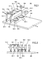
- FIG. 1 shows a strand guiding device 100 for guiding a metal strip 200, in particular a slab.
- the slab 200 is transported in a transport direction R.
- the strand guiding device 100 comprises a segment frame (not shown here) with at least one traverse 112-1 arranged upstream in the transport direction R and a downstream traverse 112 + 2 (see FIG FIG. 2 ), which are arranged parallel to one another and transversely to the transport direction R stationary. Between the upstream and the downstream traverse 112 -1, 112 +1 and parallel to these, a first guide element 120-0 is mounted.
- the first guide element is mounted vertically displaceable transversely to the plane of the metal strip.
- a measuring roller 120 for supporting the metal strip 200 is rotatably mounted on the first guide element 112 -0.
- the first guide element 112 -0 is by means of links 130 -1, 130 -2 preferably at the upper edge O of the upstream stationary cross member 112 -1 and by means of links 130 -3, 130 -4 preferably at the lower edge U of the downstream stationary crossbar 112th +1 vertically displaceable or oscillatory stored.
- the upstream cross member 112 -1 and the downstream traverse 112 +1 (dash-dotted lines) the guide element 112-0 immediately adjacent.
- an adjusting device for adjusting the guide element with the measuring roller 120 against the metal strip 200 is shown.
- the adjusting device is preferably in the form of two position-controlled hydraulic cylinders 150a, 150b, which engage at the level of the edges of the metal strip on the guide element 120-0.
- the adjusting device could also comprise only one position-controlled hydraulic cylinder, which is then preferably arranged so that it acts in the middle of the guide element.
- the strand guiding device or the steel device comprises a pressure measuring device 160a, 160b for detecting a force exerted on the measuring roller 120 by the metal strip 200, possibly due to its ferrostatic pressure.
- the pressure measuring device is designed to detect the action of force on the measuring roller in the form of the pressure in the hydraulic cylinder 150a, 150b of the actuating device.
- the adjusting device further comprises a displacement measuring device (162a, 162b) for detecting the respective of the guide element or. the measuring roller 120 against a reference point, e.g. the segment frame, traveled distance.
- the path measuring device is integrated in the Hydrualikzylindern for detecting the distance in the form of the distance traveled by the cylinders way.
- Both the pressure and force values detected by the pressure measuring device and the distances covered by the displacement measuring device are advantageously evaluated by an evaluation device in order to obtain information about To obtain the consistency of the metal strip, such as a slab, in particular with regard to the degree of its solidification.
- FIG. 2 shows a second embodiment of the strand guide device according to the invention in a cross-sectional view.
- the second embodiment differs from the first embodiment in that the links 130-1, 130-3 for supporting and supporting the guide element 112-0 are not connected to the cross members 120-1, 120 + 1 immediately adjacent to the guide element 120-0, but are each attached to the next traverses 112 -2, 112 +2.
- the handlebars 130-3, 130-4 are passed in the adjacent traverse 120 +1 between the lower edge-U and the segment rollers 120 + 1.
- the adjacent, upstream in the transport direction R Traverse 120 -1 is bridged by the handlebars 130 -1, 130 -2 contactless.
- the links 130 may be formed longer than in the first embodiment; This has the advantage that the guide element 120-0 together with the measuring roller 120 can perform larger oscillation strokes than in the first embodiment.
- FIG. 3 shows a third embodiment of the strand guide device according to the invention in a cross-sectional view.
- the third embodiment differs from the first and second embodiments in that the handlebars 130 -1, 130 -3 support and support the guide element 112-0 only relative to a directly or indirectly adjacent crossbeam.
- the traverse may be upstream or downstream of the guide element 112 -0 in the transport direction R.
- the links (130) may be designed as rigid connecting elements with joints arranged on both sides or as flexible elastic connecting elements, for example as leaf springs.
Landscapes
- Engineering & Computer Science (AREA)
- Mechanical Engineering (AREA)
- Advancing Webs (AREA)
- Registering, Tensioning, Guiding Webs, And Rollers Therefor (AREA)
Description
Die Erfindung betrifft eine Strangführungseinrichtung zum Führen eines Metallbandes, insbesondere einer Bramme.The invention relates to a strand guiding device for guiding a metal strip, in particular a slab.
Eine derartige Strangführungseinrichtung ist zum Beispiel aus der europäischen Patentanmeldung
Ausgehend von diesem Stand der Technik liegt der Erfindung die Aufgabe zu Grunde, eine bekannte Strangführungseinrichtung dahingehend weiterzubilden, dass die Lagerung des vertikal verschiebbaren Führungselementes mit der Messrolle vereinfacht ausgebildet ist.Based on this prior art, the invention is based on the object to further develop a known strand guiding device to the effect that the storage of the vertically displaceable guide element is formed simplified with the measuring roller.
Diese Aufgabe wird durch den Gegenstand des Patentanspruchs 1 gelöst. Demnach ist das Führungselement mit Hilfe von Lenkern an der ortsfesten Traverse vertikal verschiebbar gelagert und abgestützt.This object is solved by the subject matter of
Der Begriff "ortsfest" ist bei der vorliegenden Beschreibung im Sinne von ruhend gegenüber dem vertikal verschiebbaren bzw. oszillierbaren Führungselement mit der Messrolle und ruhend gegenüber dem transportierten Metallband zu verstehen.The term "stationary" is to be understood in the present description in the sense of resting against the vertically displaceable or oscillatable guide element with the measuring roller and resting against the transported metal strip.
Die beanspruchte Verwendung der Lenker zur Lagerung des Führungselementes mit der Messrolle gestattet zwar eine gewünschte Bewegung des Führungselementes vertikal zur Ebene des Metallbandes, aber eine Bewegung des Führungselementes in Transportrichtung des Metallbandes und in Breitenrichtung des Metallbandes wird wirkungsvoll unterbunden. Dies hat den Vorteil, dass das im Stand der Technik erforderliche zweite Führungselement sowie die dort zur Stabilisierung des ersten Führungselementes benötigten Druckfedern, Gleitsteine und Seile eingespart werden können. Insbesondere durch den Wegfall des aus dem Stand der Technik bekannten zweiten Führungsetementes kann das erfindungsgemäße Führungselement mit der Messerolle nun auch bei Strangführungseinrichtungen eingesetzt werden, bei denen die Traversen relativ eng zueinander beabstandet angeordnet sind, d.h. bei engen Einbauräumen.Although the claimed use of the links for supporting the guide element with the measuring roller permits a desired movement of the guide element vertically to the plane of the metal strip, but a movement of the guide element in the transport direction of the metal strip and in the width direction of the metal strip is effectively prevented. This has the advantage that the second guide element required in the prior art as well as the pressure springs, sliding blocks and cables required there for stabilizing the first guide element can be saved. In particular, by eliminating the well-known from the prior art second Führungsetementes guide element according to the invention with the knife roller can now also be used in strand guiding devices, in which the trusses are arranged relatively closely spaced from each other, i. in tight installation spaces.
Die Traverse(n), sei(en) sie vorgelagert und/oder nachgelagert, an denen die Lenker zur Halterung des Führungselementes mit Messrolle befestigt ist/sind, kann /können zu dem Führungselement mit der Messrolle unmittelbar benachbart angeordnet sein. Alternativ können zwischen der vorgelagerten Traverse und dem Führungselement mit der Messrolle und/oder zwischen der nachgelagerten Traverse und dem Führungselement mit der Messrolle weitere Traversen, vorzugsweise mit Segmentrollen, angeordnet sein. Die weiteren bzw. zwischenliegenden Traversen werden dann von den Lenkern vorzugsweiseberührungslos überbrückt.The traverse (s), be it (s) upstream and / or downstream, where the handlebar is attached to support the guide element with measuring roller / can be arranged to the guide element with the measuring roller immediately adjacent. Alternatively, between the upstream cross member and the guide element with the measuring roller and / or between the downstream cross member and the guide element with the measuring roller further trusses, preferably with segmented rollers, may be arranged. The other or intermediate trusses are then preferably bridged without contact by the handlebars.
Die Messrolle kann antriebslos oder mithilfe einer Antriebseinrichtung antreibbar ausgebildet sein.The measuring roller can be driveless or drivable by means of a drive device.
Weitere vorteilhafte Ausgestaltungen der Strangführungseinrichtung, insbesondere der Lenker, der Stelleinrichtung zum Anstellen des Führungselementes mit der Messrolle gegen das Metallband und der Druck- und/oder Wegmesseinrichtung sind Gegenstand der Unteransprüche.Further advantageous embodiments of the strand guide device, in particular the link, the adjusting device for hiring the guide element with the measuring roller against the metal strip and the pressure and / or displacement measuring device are the subject of the dependent claims.
Der Beschreibung sind drei Figuren beigefügt, wobei
- Figur 1:
- ein erstes Ausführungsbeispiel für die erfindungsgemäße Strangführungseinrichtung;
- Figur 2:
- ein zweites Ausführungsbeispiel für die erfindungsgemäße Strangführungseinrichtung; und
- Figur 3:
- ein drittes Ausführungsbeispiel für die erfindungsgemäße Strangführungseinrichtung
- FIG. 1:
- a first embodiment of the strand guiding device according to the invention;
- FIG. 2:
- A second embodiment of the strand guide device according to the invention; and
- FIG. 3:
- a third embodiment of the strand guiding device according to the invention
Die Erfindung wird nachfolgend in Form von Ausführungsbeispielen unter Bezugnahme auf die genannten Figuren detailliert beschrieben. In allen Figuren sind gleiche Elemente mit gleichen Bezugszeichen bezeichnet.The invention will now be described in detail in the form of embodiments with reference to said figures. In all figures, like elements are designated by like reference numerals.
Bei dem in
In
Weiterhin umfasst die Strangführungseinrichtung bzw. die Stahleinrichtung eine Druckmesseinrichtung 160a, 160b zum Erfassen einer durch das Metallband 200, ggf. aufgrund von dessen ferrostatischem Druck, auf die Messrolle 120 ausgeübten Krafteinwirkung. Vorzugsweise ist die Druckmesseinrichtung ausgebildet zum Erfassen der Krafteinwirkung auf die Messrolle in Form des Druckes in den Hydraulikzylinder 150a, 150b der Stelleinrichtung.Furthermore, the strand guiding device or the steel device comprises a
Schließlich umfasst die Stelleinrichtung weiterhin eine Wegmesseinrichtung (162a, 162b) zum Erfassen der jeweils von dem Führungselementbzw. der Messrolle 120 gegenüber einem Bezugspunkt, z.B. dem Segmentrahmen, zurückgelegten Wegstrecke. Vorzugsweise ist die Wegmesseinrichtung in den Hydrualikzylindern integriert zum Erfassen der Wegstrecke in Form des von den Zylindern zurückgelegten Weges.Finally, the adjusting device further comprises a displacement measuring device (162a, 162b) for detecting the respective of the guide element or. the
Sowohl die von der Druckmesseinrichtung erfassten Druck- bzw. Kraftwerte wie auch die von der Wegmesseinrichtung erfassten Wegstrecken werden vorteilhafter Weise von einer Auswerteeinrichtung ausgewertet, um eine Aussage über die Konsistenz des Metallbandes, beispielsweise einer Bramme, zu erhalten, insbesondere im Hinblick auf den Grad von dessen Durcherstarrung.Both the pressure and force values detected by the pressure measuring device and the distances covered by the displacement measuring device are advantageously evaluated by an evaluation device in order to obtain information about To obtain the consistency of the metal strip, such as a slab, in particular with regard to the degree of its solidification.
Die soeben beschriebenen Mess- und Auswerteeinrichtungen sind zwar nur in
Bei allen Ausführungsbeispielen können die Lenker (130) als starre Verbindungselemente mit beidseitig angeordneten Gelenken oder als biegeelastische Verbindungselemente, beispielsweise als Blattfedern, ausgebildet sein.In all embodiments, the links (130) may be designed as rigid connecting elements with joints arranged on both sides or as flexible elastic connecting elements, for example as leaf springs.
Claims (11)
- Strip guide device (100) for guiding a metal strip (200), particularly a slab, in a transport direction (R), comprising:at least one segment frame with at least one cross member (112 -1; 112 +1), which is arranged to be stationary oriented in width direction of the metal strip;a guide element (112 -0) arranged substantially parallel to the cross member and mounted to be vertically displaceable transversely to the plane of the metal strip (200); anda segment roller, which is rotatably mounted at the guide element (112 -0) in the form of a measuring roller (120) for contacting the metal strip (200);characterised in that the guide element (112 -0) is mounted and supported with the help of guides (130 -n) at the stationary cross member (112 -1, 112 -2; 112 +1, 112 +2) to be vertically displaceable.
- Strip guide device (100) according to claim 1, characterised in that at least a first one of the guides (130 -1) connects the upper edge of the cross member (112 -1) with the upper edge of the guide element (112 -0) and at least a second one of the guides (130 -3) connects the lower edge of the cross member (112 -1) with the lower edge of the guide element.
- Strip guide device (100) according to claim 1, characterised in that the segment frame comprises at least one cross member (112 -1, 112 +1) mounted to be stationary relative to the guide element (120 -0) upstream in the transport direction (R) and at least one cross member (112 -1, 112 +1) mounted to be stationary relative to the guide element downstream in the transport direction; that at least a first one of the guides (130 -1; 130 -2) connects the lower edge (U), which faces the measuring roller, of the guide element (112 - 0) with the lower edge of the upstream cross member (112 -1) and at least a second one of the guides (130 -3, 130 -4) connects the upper edge (O), which is opposite the lower edge, of the guide element (112 -0) with the upper edge of the downstream cross member (112+1).
- Strip guide device (100) according to any one of the preceding claims, characterised in that the at least one stationary cross member (112 -1, 112 +1) is arranged directly adjacent to the guide element.
- Strip guide device (100) according to claim 3, characterised in that at least one further cross member (120 -1, 120 +1), preferably with segment rollers (120 -1, 120 +1), is arranged between the upstream cross member (112 -2) and the guide element (112 -0) with the measuring roller (120) and/or between the downstream cross member (112 +2) and the guide element (112 -0) with the measuring roller; and that the further cross member (120 -1, 120 +1) is bridged over, preferably contactlessly, by the guides (130).
- Strip guide device (100) according to any one of the preceding claims, characterised in that the guides (130) are constructed as rigid connecting elements with guides arranged at both sides or as resilient connecting elements, for example as leaf springs.
- Strip guide device (100) according to any one of the preceding claims, characterised by a drive device (14) for driving the measuring roller (120) in a rotational movement.
- Strip guide device according to any one of the preceding claims, characterised by a setting device in the form of at least one hydraulic cylinder (150a, 150b), which is controlled in drive and which engages the guide element (120 -0), for adjusting the guide element with the measuring roller (120) relative to the metal strip (200).
- Strip guide device (100) according to any one of the preceding claims, characterised by a pressure measuring device (160a, 160b) for detecting a force action exerted by the metal strip (200), optionally through the ferrostatic pressure thereof, on the measuring roller (120).
- Strip guide device according to claim 9, characterised in that the pressure measuring device (160a, 160b) is constructed to detect the force, which is exerted by the metal strip (200) on the measuring roller (120), in the form of the pressure in the hydraulic cylinders (150a, 150b) of the setting device.
- Strip guide device (100) according to any one of the preceding claims, characterised by a travel measuring device (162a, 162b) for detecting a travel path covered by the guide element or by the measuring roller relative to a reference point, for example the segment frame.
Applications Claiming Priority (3)
| Application Number | Priority Date | Filing Date | Title |
|---|---|---|---|
| DE102006025779 | 2006-05-31 | ||
| DE102006033370A DE102006033370A1 (en) | 2006-05-31 | 2006-07-19 | Strand guiding device for guiding a metal strip |
| PCT/EP2007/004411 WO2007137712A1 (en) | 2006-05-31 | 2007-05-16 | Strand guide installation for guiding a metal strip |
Publications (2)
| Publication Number | Publication Date |
|---|---|
| EP1896204A1 EP1896204A1 (en) | 2008-03-12 |
| EP1896204B1 true EP1896204B1 (en) | 2009-07-15 |
Family
ID=38537823
Family Applications (1)
| Application Number | Title | Priority Date | Filing Date |
|---|---|---|---|
| EP07725326A Not-in-force EP1896204B1 (en) | 2006-05-31 | 2007-05-16 | Strand guide installation for guiding a metal strip |
Country Status (4)
| Country | Link |
|---|---|
| EP (1) | EP1896204B1 (en) |
| DE (2) | DE102006033370A1 (en) |
| ES (1) | ES2327014T3 (en) |
| WO (1) | WO2007137712A1 (en) |
Families Citing this family (2)
| Publication number | Priority date | Publication date | Assignee | Title |
|---|---|---|---|---|
| DE102008009136A1 (en) * | 2008-02-14 | 2009-10-15 | Sms Siemag Aktiengesellschaft | Strand guide, in particular for a continuous steel slab caster |
| DE102017117634A1 (en) * | 2017-08-03 | 2019-02-07 | Salzgitter Flachstahl Gmbh | Optimized continuous casting plant and process for the optimized alignment of components of a continuous casting plant |
Family Cites Families (1)
| Publication number | Priority date | Publication date | Assignee | Title |
|---|---|---|---|---|
| DE10349962B3 (en) * | 2003-10-24 | 2005-06-02 | Ingo Dr. Schubert | Arrangement for determining the consistency of a cast strand in a continuous casting plant and / or its mouth width |
-
2006
- 2006-07-19 DE DE102006033370A patent/DE102006033370A1/en not_active Withdrawn
-
2007
- 2007-05-16 EP EP07725326A patent/EP1896204B1/en not_active Not-in-force
- 2007-05-16 WO PCT/EP2007/004411 patent/WO2007137712A1/en active Application Filing
- 2007-05-16 DE DE502007001059T patent/DE502007001059D1/en active Active
- 2007-05-16 ES ES07725326T patent/ES2327014T3/en active Active
Also Published As
| Publication number | Publication date |
|---|---|
| DE502007001059D1 (en) | 2009-08-27 |
| DE102006033370A1 (en) | 2007-12-06 |
| ES2327014T3 (en) | 2009-10-22 |
| WO2007137712A1 (en) | 2007-12-06 |
| EP1896204A1 (en) | 2008-03-12 |
Similar Documents
| Publication | Publication Date | Title |
|---|---|---|
| EP2938445B1 (en) | Device and method for laterally guiding a rolled or cast product on a transport track | |
| EP0531491B1 (en) | Roll press | |
| EP2666560A1 (en) | Straightening machine with adjustable support roll mounts | |
| WO2009065401A1 (en) | Device for deep-rolling transition radii on crankshafts | |
| DE3119677A1 (en) | "MACHINE SUPER CALENDAR FOR PAPER OR THE LIKE" | |
| EP1896204B1 (en) | Strand guide installation for guiding a metal strip | |
| DE102008014524A1 (en) | Continuous casting plant with a device for determining solidification states of a cast strand and method therefor | |
| WO2017174275A1 (en) | Guide carriage having deformation sensor on track element | |
| DE202009015980U1 (en) | Replacement device for exchanging a flexible sheath, belt or sieve | |
| DE102009023110A1 (en) | Blank alignment device for use in folding and pasting machine, has thrust component transferred to blanks, and blanks held in lateral contact with guiding surface, where component is arranged transverse to conveyor direction | |
| EP0389073A1 (en) | Device for noise-deficient buffering and transverse-transport of elongated rolling stock | |
| EP2525928B2 (en) | Strand guide segment for guiding and supporting a metallic strand in a continuous casting machine | |
| DE19817002A1 (en) | Apparatus for descaling of semifinished products e.g. metal strips and sheets | |
| DE3400608C2 (en) | Roll stand with an offset intermediate roll inserted between the work roll and the back-up roll | |
| DE2418695A1 (en) | DEVICE FOR CONTROLLING THE WIDTH AND TRANSVERSAL TENSION OF MOVING MATERIAL TRAILS | |
| DE10362038A1 (en) | Method and device for controlling the contact pressure of a pressure roller to a goods guide roller | |
| DE10040271A1 (en) | Device for the continuous casting of metals, in particular steel | |
| DE102006002929B4 (en) | Component for a continuous casting device | |
| DE60110818T2 (en) | DEVICE FOR VARIATING THE POSITIONING OF ROLLING ROLLERS FOR FLAT PRODUCTS | |
| EP1449958B1 (en) | Device for the treatment, in particular for low pressure treatment, of the wire or felt of a papermachine | |
| DE19711241C2 (en) | Calender for paper and similar web material | |
| EP2666558A1 (en) | Lateral guide for a mill train | |
| DE10152438A1 (en) | Snow gliding board, in particular skis, and spreading device for a snow gliding board | |
| DE102004021871B4 (en) | Plant for the chemical treatment of the surface of strip material | |
| DE102005044538B4 (en) | Conveyor device |
Legal Events
| Date | Code | Title | Description |
|---|---|---|---|
| PUAI | Public reference made under article 153(3) epc to a published international application that has entered the european phase |
Free format text: ORIGINAL CODE: 0009012 |
|
| 17P | Request for examination filed |
Effective date: 20080108 |
|
| AK | Designated contracting states |
Kind code of ref document: A1 Designated state(s): AT BE BG CH CY CZ DE DK EE ES FI FR GB GR HU IE IS IT LI LT LU LV MC MT NL PL PT RO SE SI SK TR |
|
| AX | Request for extension of the european patent |
Extension state: AL BA HR MK YU |
|
| RAX | Requested extension states of the european patent have changed |
Extension state: MK Extension state: RS Extension state: HR Extension state: BA Extension state: AL |
|
| GRAP | Despatch of communication of intention to grant a patent |
Free format text: ORIGINAL CODE: EPIDOSNIGR1 |
|
| DAX | Request for extension of the european patent (deleted) | ||
| RIN1 | Information on inventor provided before grant (corrected) |
Inventor name: DIE ERFINDER HABEN AUF IHRE NENNUNG VERZICHTET. |
|
| GRAS | Grant fee paid |
Free format text: ORIGINAL CODE: EPIDOSNIGR3 |
|
| GRAA | (expected) grant |
Free format text: ORIGINAL CODE: 0009210 |
|
| RAP1 | Party data changed (applicant data changed or rights of an application transferred) |
Owner name: SMS SIEMAG AG |
|
| AK | Designated contracting states |
Kind code of ref document: B1 Designated state(s): AT BE BG CH CY CZ DE DK EE ES FI FR GB GR HU IE IS IT LI LT LU LV MC MT NL PL PT RO SE SI SK TR |
|
| REG | Reference to a national code |
Ref country code: CH Ref legal event code: EP Ref country code: GB Ref legal event code: FG4D Free format text: NOT ENGLISH |
|
| REG | Reference to a national code |
Ref country code: IE Ref legal event code: FG4D |
|
| REF | Corresponds to: |
Ref document number: 502007001059 Country of ref document: DE Date of ref document: 20090827 Kind code of ref document: P |
|
| REG | Reference to a national code |
Ref country code: ES Ref legal event code: FG2A Ref document number: 2327014 Country of ref document: ES Kind code of ref document: T3 |
|
| NLV1 | Nl: lapsed or annulled due to failure to fulfill the requirements of art. 29p and 29m of the patents act | ||
| PG25 | Lapsed in a contracting state [announced via postgrant information from national office to epo] |
Ref country code: SE Free format text: LAPSE BECAUSE OF FAILURE TO SUBMIT A TRANSLATION OF THE DESCRIPTION OR TO PAY THE FEE WITHIN THE PRESCRIBED TIME-LIMIT Effective date: 20090715 Ref country code: FI Free format text: LAPSE BECAUSE OF FAILURE TO SUBMIT A TRANSLATION OF THE DESCRIPTION OR TO PAY THE FEE WITHIN THE PRESCRIBED TIME-LIMIT Effective date: 20090715 Ref country code: IS Free format text: LAPSE BECAUSE OF FAILURE TO SUBMIT A TRANSLATION OF THE DESCRIPTION OR TO PAY THE FEE WITHIN THE PRESCRIBED TIME-LIMIT Effective date: 20091115 Ref country code: LT Free format text: LAPSE BECAUSE OF FAILURE TO SUBMIT A TRANSLATION OF THE DESCRIPTION OR TO PAY THE FEE WITHIN THE PRESCRIBED TIME-LIMIT Effective date: 20090715 |
|
| REG | Reference to a national code |
Ref country code: IE Ref legal event code: FD4D |
|
| PG25 | Lapsed in a contracting state [announced via postgrant information from national office to epo] |
Ref country code: NL Free format text: LAPSE BECAUSE OF FAILURE TO SUBMIT A TRANSLATION OF THE DESCRIPTION OR TO PAY THE FEE WITHIN THE PRESCRIBED TIME-LIMIT Effective date: 20090715 Ref country code: SI Free format text: LAPSE BECAUSE OF FAILURE TO SUBMIT A TRANSLATION OF THE DESCRIPTION OR TO PAY THE FEE WITHIN THE PRESCRIBED TIME-LIMIT Effective date: 20090715 Ref country code: LV Free format text: LAPSE BECAUSE OF FAILURE TO SUBMIT A TRANSLATION OF THE DESCRIPTION OR TO PAY THE FEE WITHIN THE PRESCRIBED TIME-LIMIT Effective date: 20090715 Ref country code: PL Free format text: LAPSE BECAUSE OF FAILURE TO SUBMIT A TRANSLATION OF THE DESCRIPTION OR TO PAY THE FEE WITHIN THE PRESCRIBED TIME-LIMIT Effective date: 20090715 |
|
| PG25 | Lapsed in a contracting state [announced via postgrant information from national office to epo] |
Ref country code: BG Free format text: LAPSE BECAUSE OF FAILURE TO SUBMIT A TRANSLATION OF THE DESCRIPTION OR TO PAY THE FEE WITHIN THE PRESCRIBED TIME-LIMIT Effective date: 20091015 Ref country code: PT Free format text: LAPSE BECAUSE OF FAILURE TO SUBMIT A TRANSLATION OF THE DESCRIPTION OR TO PAY THE FEE WITHIN THE PRESCRIBED TIME-LIMIT Effective date: 20091115 |
|
| PG25 | Lapsed in a contracting state [announced via postgrant information from national office to epo] |
Ref country code: IE Free format text: LAPSE BECAUSE OF FAILURE TO SUBMIT A TRANSLATION OF THE DESCRIPTION OR TO PAY THE FEE WITHIN THE PRESCRIBED TIME-LIMIT Effective date: 20090715 Ref country code: EE Free format text: LAPSE BECAUSE OF FAILURE TO SUBMIT A TRANSLATION OF THE DESCRIPTION OR TO PAY THE FEE WITHIN THE PRESCRIBED TIME-LIMIT Effective date: 20090715 Ref country code: DK Free format text: LAPSE BECAUSE OF FAILURE TO SUBMIT A TRANSLATION OF THE DESCRIPTION OR TO PAY THE FEE WITHIN THE PRESCRIBED TIME-LIMIT Effective date: 20090715 Ref country code: CZ Free format text: LAPSE BECAUSE OF FAILURE TO SUBMIT A TRANSLATION OF THE DESCRIPTION OR TO PAY THE FEE WITHIN THE PRESCRIBED TIME-LIMIT Effective date: 20090715 Ref country code: RO Free format text: LAPSE BECAUSE OF FAILURE TO SUBMIT A TRANSLATION OF THE DESCRIPTION OR TO PAY THE FEE WITHIN THE PRESCRIBED TIME-LIMIT Effective date: 20090715 |
|
| PLBE | No opposition filed within time limit |
Free format text: ORIGINAL CODE: 0009261 |
|
| STAA | Information on the status of an ep patent application or granted ep patent |
Free format text: STATUS: NO OPPOSITION FILED WITHIN TIME LIMIT |
|
| PG25 | Lapsed in a contracting state [announced via postgrant information from national office to epo] |
Ref country code: SK Free format text: LAPSE BECAUSE OF FAILURE TO SUBMIT A TRANSLATION OF THE DESCRIPTION OR TO PAY THE FEE WITHIN THE PRESCRIBED TIME-LIMIT Effective date: 20090715 |
|
| 26N | No opposition filed |
Effective date: 20100416 |
|
| BERE | Be: lapsed |
Owner name: SMS SIEMAG AG Effective date: 20100531 |
|
| PG25 | Lapsed in a contracting state [announced via postgrant information from national office to epo] |
Ref country code: MC Free format text: LAPSE BECAUSE OF NON-PAYMENT OF DUE FEES Effective date: 20100531 |
|
| REG | Reference to a national code |
Ref country code: FR Ref legal event code: ST Effective date: 20110131 |
|
| PG25 | Lapsed in a contracting state [announced via postgrant information from national office to epo] |
Ref country code: BE Free format text: LAPSE BECAUSE OF NON-PAYMENT OF DUE FEES Effective date: 20100531 Ref country code: IT Free format text: LAPSE BECAUSE OF NON-PAYMENT OF DUE FEES Effective date: 20100516 |
|
| PG25 | Lapsed in a contracting state [announced via postgrant information from national office to epo] |
Ref country code: MT Free format text: LAPSE BECAUSE OF FAILURE TO SUBMIT A TRANSLATION OF THE DESCRIPTION OR TO PAY THE FEE WITHIN THE PRESCRIBED TIME-LIMIT Effective date: 20090715 |
|
| PG25 | Lapsed in a contracting state [announced via postgrant information from national office to epo] |
Ref country code: FR Free format text: LAPSE BECAUSE OF NON-PAYMENT OF DUE FEES Effective date: 20100531 |
|
| REG | Reference to a national code |
Ref country code: CH Ref legal event code: PL |
|
| PG25 | Lapsed in a contracting state [announced via postgrant information from national office to epo] |
Ref country code: LI Free format text: LAPSE BECAUSE OF NON-PAYMENT OF DUE FEES Effective date: 20110531 Ref country code: CH Free format text: LAPSE BECAUSE OF NON-PAYMENT OF DUE FEES Effective date: 20110531 |
|
| PG25 | Lapsed in a contracting state [announced via postgrant information from national office to epo] |
Ref country code: CY Free format text: LAPSE BECAUSE OF FAILURE TO SUBMIT A TRANSLATION OF THE DESCRIPTION OR TO PAY THE FEE WITHIN THE PRESCRIBED TIME-LIMIT Effective date: 20090715 |
|
| PG25 | Lapsed in a contracting state [announced via postgrant information from national office to epo] |
Ref country code: HU Free format text: LAPSE BECAUSE OF FAILURE TO SUBMIT A TRANSLATION OF THE DESCRIPTION OR TO PAY THE FEE WITHIN THE PRESCRIBED TIME-LIMIT Effective date: 20100116 Ref country code: LU Free format text: LAPSE BECAUSE OF NON-PAYMENT OF DUE FEES Effective date: 20100516 |
|
| PG25 | Lapsed in a contracting state [announced via postgrant information from national office to epo] |
Ref country code: TR Free format text: LAPSE BECAUSE OF FAILURE TO SUBMIT A TRANSLATION OF THE DESCRIPTION OR TO PAY THE FEE WITHIN THE PRESCRIBED TIME-LIMIT Effective date: 20090715 |
|
| PGFP | Annual fee paid to national office [announced via postgrant information from national office to epo] |
Ref country code: ES Payment date: 20120521 Year of fee payment: 6 |
|
| PGFP | Annual fee paid to national office [announced via postgrant information from national office to epo] |
Ref country code: AT Payment date: 20120511 Year of fee payment: 6 |
|
| PGFP | Annual fee paid to national office [announced via postgrant information from national office to epo] |
Ref country code: GB Payment date: 20130521 Year of fee payment: 7 Ref country code: DE Payment date: 20130522 Year of fee payment: 7 |
|
| PGFP | Annual fee paid to national office [announced via postgrant information from national office to epo] |
Ref country code: IT Payment date: 20130530 Year of fee payment: 7 |
|
| PG25 | Lapsed in a contracting state [announced via postgrant information from national office to epo] |
Ref country code: GR Free format text: LAPSE BECAUSE OF FAILURE TO SUBMIT A TRANSLATION OF THE DESCRIPTION OR TO PAY THE FEE WITHIN THE PRESCRIBED TIME-LIMIT Effective date: 20090715 |
|
| REG | Reference to a national code |
Ref country code: DE Ref legal event code: R119 Ref document number: 502007001059 Country of ref document: DE |
|
| REG | Reference to a national code |
Ref country code: AT Ref legal event code: MM01 Ref document number: 436319 Country of ref document: AT Kind code of ref document: T Effective date: 20140516 |
|
| GBPC | Gb: european patent ceased through non-payment of renewal fee |
Effective date: 20140516 |
|
| REG | Reference to a national code |
Ref country code: DE Ref legal event code: R119 Ref document number: 502007001059 Country of ref document: DE Effective date: 20141202 |
|
| PG25 | Lapsed in a contracting state [announced via postgrant information from national office to epo] |
Ref country code: AT Free format text: LAPSE BECAUSE OF NON-PAYMENT OF DUE FEES Effective date: 20140516 |
|
| PG25 | Lapsed in a contracting state [announced via postgrant information from national office to epo] |
Ref country code: DE Free format text: LAPSE BECAUSE OF NON-PAYMENT OF DUE FEES Effective date: 20141202 Ref country code: IT Free format text: LAPSE BECAUSE OF NON-PAYMENT OF DUE FEES Effective date: 20140516 |
|
| PG25 | Lapsed in a contracting state [announced via postgrant information from national office to epo] |
Ref country code: GB Free format text: LAPSE BECAUSE OF NON-PAYMENT OF DUE FEES Effective date: 20140516 |
|
| REG | Reference to a national code |
Ref country code: ES Ref legal event code: FD2A Effective date: 20150701 |
|
| PG25 | Lapsed in a contracting state [announced via postgrant information from national office to epo] |
Ref country code: ES Free format text: LAPSE BECAUSE OF NON-PAYMENT OF DUE FEES Effective date: 20140517 |