EP1886259B1 - Automatic remote acquisition system for determining the configuration of an installation - Google Patents
Automatic remote acquisition system for determining the configuration of an installation Download PDFInfo
- Publication number
- EP1886259B1 EP1886259B1 EP05778893A EP05778893A EP1886259B1 EP 1886259 B1 EP1886259 B1 EP 1886259B1 EP 05778893 A EP05778893 A EP 05778893A EP 05778893 A EP05778893 A EP 05778893A EP 1886259 B1 EP1886259 B1 EP 1886259B1
- Authority
- EP
- European Patent Office
- Prior art keywords
- transponder
- identification data
- write
- read
- fitted
- Prior art date
- Legal status (The legal status is an assumption and is not a legal conclusion. Google has not performed a legal analysis and makes no representation as to the accuracy of the status listed.)
- Not-in-force
Links
Images


Classifications
-
- G—PHYSICS
- G06—COMPUTING; CALCULATING OR COUNTING
- G06K—GRAPHICAL DATA READING; PRESENTATION OF DATA; RECORD CARRIERS; HANDLING RECORD CARRIERS
- G06K19/00—Record carriers for use with machines and with at least a part designed to carry digital markings
- G06K19/06—Record carriers for use with machines and with at least a part designed to carry digital markings characterised by the kind of the digital marking, e.g. shape, nature, code
- G06K19/067—Record carriers with conductive marks, printed circuits or semiconductor circuit elements, e.g. credit or identity cards also with resonating or responding marks without active components
- G06K19/07—Record carriers with conductive marks, printed circuits or semiconductor circuit elements, e.g. credit or identity cards also with resonating or responding marks without active components with integrated circuit chips
- G06K19/077—Constructional details, e.g. mounting of circuits in the carrier
- G06K19/07749—Constructional details, e.g. mounting of circuits in the carrier the record carrier being capable of non-contact communication, e.g. constructional details of the antenna of a non-contact smart card
- G06K19/07758—Constructional details, e.g. mounting of circuits in the carrier the record carrier being capable of non-contact communication, e.g. constructional details of the antenna of a non-contact smart card arrangements for adhering the record carrier to further objects or living beings, functioning as an identification tag
-
- G—PHYSICS
- G06—COMPUTING; CALCULATING OR COUNTING
- G06K—GRAPHICAL DATA READING; PRESENTATION OF DATA; RECORD CARRIERS; HANDLING RECORD CARRIERS
- G06K17/00—Methods or arrangements for effecting co-operative working between equipments covered by two or more of main groups G06K1/00 - G06K15/00, e.g. automatic card files incorporating conveying and reading operations
-
- G—PHYSICS
- G06—COMPUTING; CALCULATING OR COUNTING
- G06K—GRAPHICAL DATA READING; PRESENTATION OF DATA; RECORD CARRIERS; HANDLING RECORD CARRIERS
- G06K19/00—Record carriers for use with machines and with at least a part designed to carry digital markings
- G06K19/06—Record carriers for use with machines and with at least a part designed to carry digital markings characterised by the kind of the digital marking, e.g. shape, nature, code
- G06K19/067—Record carriers with conductive marks, printed circuits or semiconductor circuit elements, e.g. credit or identity cards also with resonating or responding marks without active components
- G06K19/07—Record carriers with conductive marks, printed circuits or semiconductor circuit elements, e.g. credit or identity cards also with resonating or responding marks without active components with integrated circuit chips
- G06K19/0723—Record carriers with conductive marks, printed circuits or semiconductor circuit elements, e.g. credit or identity cards also with resonating or responding marks without active components with integrated circuit chips the record carrier comprising an arrangement for non-contact communication, e.g. wireless communication circuits on transponder cards, non-contact smart cards or RFIDs
- G06K19/0726—Record carriers with conductive marks, printed circuits or semiconductor circuit elements, e.g. credit or identity cards also with resonating or responding marks without active components with integrated circuit chips the record carrier comprising an arrangement for non-contact communication, e.g. wireless communication circuits on transponder cards, non-contact smart cards or RFIDs the arrangement including a circuit for tuning the resonance frequency of an antenna on the record carrier
-
- G—PHYSICS
- G06—COMPUTING; CALCULATING OR COUNTING
- G06K—GRAPHICAL DATA READING; PRESENTATION OF DATA; RECORD CARRIERS; HANDLING RECORD CARRIERS
- G06K19/00—Record carriers for use with machines and with at least a part designed to carry digital markings
- G06K19/06—Record carriers for use with machines and with at least a part designed to carry digital markings characterised by the kind of the digital marking, e.g. shape, nature, code
- G06K19/067—Record carriers with conductive marks, printed circuits or semiconductor circuit elements, e.g. credit or identity cards also with resonating or responding marks without active components
- G06K19/07—Record carriers with conductive marks, printed circuits or semiconductor circuit elements, e.g. credit or identity cards also with resonating or responding marks without active components with integrated circuit chips
- G06K19/077—Constructional details, e.g. mounting of circuits in the carrier
- G06K19/07749—Constructional details, e.g. mounting of circuits in the carrier the record carrier being capable of non-contact communication, e.g. constructional details of the antenna of a non-contact smart card
- G06K19/07758—Constructional details, e.g. mounting of circuits in the carrier the record carrier being capable of non-contact communication, e.g. constructional details of the antenna of a non-contact smart card arrangements for adhering the record carrier to further objects or living beings, functioning as an identification tag
- G06K19/0776—Constructional details, e.g. mounting of circuits in the carrier the record carrier being capable of non-contact communication, e.g. constructional details of the antenna of a non-contact smart card arrangements for adhering the record carrier to further objects or living beings, functioning as an identification tag the adhering arrangement being a layer of adhesive, so that the record carrier can function as a sticker
-
- G—PHYSICS
- G06—COMPUTING; CALCULATING OR COUNTING
- G06K—GRAPHICAL DATA READING; PRESENTATION OF DATA; RECORD CARRIERS; HANDLING RECORD CARRIERS
- G06K19/00—Record carriers for use with machines and with at least a part designed to carry digital markings
- G06K19/06—Record carriers for use with machines and with at least a part designed to carry digital markings characterised by the kind of the digital marking, e.g. shape, nature, code
- G06K19/067—Record carriers with conductive marks, printed circuits or semiconductor circuit elements, e.g. credit or identity cards also with resonating or responding marks without active components
- G06K19/07—Record carriers with conductive marks, printed circuits or semiconductor circuit elements, e.g. credit or identity cards also with resonating or responding marks without active components with integrated circuit chips
- G06K19/077—Constructional details, e.g. mounting of circuits in the carrier
- G06K19/07749—Constructional details, e.g. mounting of circuits in the carrier the record carrier being capable of non-contact communication, e.g. constructional details of the antenna of a non-contact smart card
- G06K19/07771—Constructional details, e.g. mounting of circuits in the carrier the record carrier being capable of non-contact communication, e.g. constructional details of the antenna of a non-contact smart card the record carrier comprising means for minimising adverse effects on the data communication capability of the record carrier, e.g. minimising Eddy currents induced in a proximate metal or otherwise electromagnetically interfering object
-
- Y—GENERAL TAGGING OF NEW TECHNOLOGICAL DEVELOPMENTS; GENERAL TAGGING OF CROSS-SECTIONAL TECHNOLOGIES SPANNING OVER SEVERAL SECTIONS OF THE IPC; TECHNICAL SUBJECTS COVERED BY FORMER USPC CROSS-REFERENCE ART COLLECTIONS [XRACs] AND DIGESTS
- Y10—TECHNICAL SUBJECTS COVERED BY FORMER USPC
- Y10T—TECHNICAL SUBJECTS COVERED BY FORMER US CLASSIFICATION
- Y10T29/00—Metal working
- Y10T29/49—Method of mechanical manufacture
- Y10T29/49002—Electrical device making
- Y10T29/49016—Antenna or wave energy "plumbing" making
Definitions
- the present invention relates to an automatic remote acquisition system for determining the configuration of an installation.
- the present invention may be used to particular advantage, though not exclusively, in an installation installed and activated at different stages, to which the following description refers purely by way of example.
- a computer network is a definite and indispensable aid to all aspects of servicing work, by constructing and maintaining a centralized data bank constituting an inventory of parts and elementary units (LRU - "Logic Replaceable Unit") of which the installation is composed.
- LRU Light Reliable Unit
- a centralized data bank is only effective to the extent that the data in it is correct, updated and reliable.
- the parts and elementary units of an installation are identified using various identification systems, one of the cheapest of which is based on the use of bar codes. More specifically, an unequivocal bar code is assigned to each part and each elementary unit in the installation, and is normally printed on a label applied to the respective installation part or elementary unit.
- a transponder 101 typically comprises a microchip 102 having an electronic memory (not shown); and a normally miniaturized antenna 103.
- transponder 101 is excited, via antenna 103, by the electromagnetic field generated by an external (fixed or portable) RFid read/write device 104, with which it dialogues by radio, and to which it returns the identification code and/or any other information memorized in microchip 102.
- the external RFid read/write device 104 is normally connectable to a computer device 105 for collecting the identification code and/or any other memorized information.
- Transponder 101 also comprises a capacitor (not shown), in which case, transponder 101 is passive, or a small battery (not shown), in which case, transponder 101 is active. Transponder 101 may also be rewritable, for remote programming with additional data, or for complete reprogramming with a new "identity".
- Figure 2 shows a few examples of transponders 101 of different sizes, which depend on performance requirements, and on the size of the elementary units to which they are applied.
- the RFid identification system is affected by transponder read noise - particularly in the case of passive transponders - caused by numerous situations, in which the magnetic component of the electromagnetic field generated by the RFid read/write device is distorted or attenuated to the point of drastically reducing the energy absorbed by the transponder antenna. More specifically, transponder reading is disturbed by:
- NL 1 016 686 C2 discloses a method for identifying a physical assembly of objects, using an identification unit having a physical relationship with and receiving identification information from the objects in the assembly, which is then identified based on all this information.
- US 2004/108378 A1 discloses a system and method for compiling a service history for a machine.
- a transmitter is attached to a serviceable part for a machine. When the part is installed, the transmitter relays an identification which is received by a receiver preferably attached to the machine.
- a processor stores the identification and associated machine data to build the service history.
- the service history data may be relayed to a remote storage system for storage and display.
- a system for automatically remotely determining the configuration of an installation is provided, as claimed in Claim 1.
- STC system The automatic remote acquisition system for determining the configuration of an installation in accordance with the present invention - hereinafter referred to simply as STC system - observes the following guide lines:
- An installation 1 normally comprises a number of different types of elementary units 2 ( Figure 3 ), such as radars, display equipment, dedicated computers, work stations, etc., which may also differ as to version or degree of customization.
- Elementary units 2 are assigned respective identification codes, which are grouped into varying configurations defining subsystems incorporated in further, more complex higher-level, subsystems according to a specific multilevel hierarchical structure.
- FIG. 3 example shows grouping of the identification codes, and therefore of the relative elementary units 2, in a four-level hierarchical structure organized by devices 3, cabinets 4, and control rooms 5.
- control rooms 5 are connected to a central control device 6 comprising a central data bank 7, e.g. a SAP database, for storing and updating information concerning the configuration of installation 1.
- a central data bank 7 e.g. a SAP database
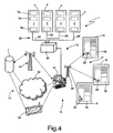
- Figure 4 shows one configuration of installation 1 associated with a control room 5 ( Figure 3 ), and which comprises a first number of four cabinets 4, each housing a number of devices forming part of a first main family of devices hereinafter referred to as standard devices 3a; and a second number of three containers 8, each housing a device forming part of a second family of devices hereinafter referred to as non-standard devices 3b.
- Standard devices 3a are of standard shape and size, and comprise basic elementary units 2 typically organized by cabinets 4 and hereinafter indicated 2a.
- Figure 5 shows an example of a cabinet 4 comprising a number of racks 9 for supporting respective standard devices 3a, each in turn comprising a respective number of elementary units 2a.
- Figure 6 shows a non-standard device 3b, which comprises heterogeneous elementary units 2 - such as displays, power supplies, junction-box plates, antennas, TWT devices, mass storage units, customized electronic boards, interfaces, COTS systems, etc. - housed in a relative container 8 normally difficult to access and inspect, and which are hereinafter indicated 2b.
- heterogeneous elementary units 2 - such as displays, power supplies, junction-box plates, antennas, TWT devices, mass storage units, customized electronic boards, interfaces, COTS systems, etc. - housed in a relative container 8 normally difficult to access and inspect, and which are hereinafter indicated 2b.
- STC system 10 indicates the STC system of control room 5 according to the present invention.
- STC system 10 comprises an automatic identification system 11 based on RFid transponder technology to read and/or modify identification data - including the identification code mentioned previously - relative to elementary units 2a, 2b ( Figures 5 and 6 ) of installation 1; a data gathering and management system 12 for gathering and organizing data read and/or modified by identification system 11; said central data bank 7 located remotely with respect to installation 1 and for memorizing and updating identification data of all elementary units 2a, 2b alongside configuration changes to installation 1; and a data transmission system 13 for data exchange between data gathering and management system 12 and central data bank 7.
- Identification system 11, data gathering and management system 12, and data transmission system 13 substantially reflect the Figure 3 hierarchical structure, and are technologically interdependent, in the sense that technological choices for one affect the others.
- central data bank 7 In addition to all the identification data of elementary units 2a, 2b of installation 1, central data bank 7 also memorizes and updates information concerning the hierarchical grouping structure ( Figure 3 ) of such identification data, so as to form a pool of information available for any servicing of installation 1.
- identification system 11 comprises a number of passive transponders 14, each fitted to, and for memorizing the identification data of, a respective elementary unit 2a, 2b of installation 1.
- Passive transponders 14 operate to ISO/IEC standard 15693, i.e. operate at a nominal radiofrequency F1 of 13.56 MHz, and have a memory capacity M1 of 1 Kbit to 2 Kbytes and a read range D1 of 10 to 120 cm.
- identification system 11 comprises a substantially straight antenna 15, which has an internal impedance of 50 ohms, is 19" long, has a respective antenna output 16, and is mounted longitudinally, by a Velcro fastener (not shown), to a side 17 of respective rack 9.
- Passive transponders 14 are mounted to walls 18 of respective elementary units 2a facing side 17 of rack 9, so as to facilitate electromagnetic coupling of antenna 15 and passive transponders 14, and so facilitate reading and writing of passive transponders 14.
- identification system 11 also comprises a control unit 19 integrated in each cabinet 4, and for reading and/or modifying the identification data of elementary units 2a memorized in respective passive transponders 14 in cabinet 4, and for transferring said data between passive transponders 14 in cabinet 4 and data gathering and management system 12 ( Figure 4 ).
- control unit 19 comprises an antenna multiplexer device 20 having a number of input ports 21, each connected to a respective antenna output 16 by a respective coaxial cable 22; an RFid read/write device 23, for passive transponders 14, output-connected to antenna multiplexer device 20 and for controlling antennas 15, via antenna multiplexer device 20, one at a time in rotation according to an interrogation cycle having a minimum switching time of 1 msec; and a microcontroller 24 output-connected to RFid read/write device 23 to transfer the identification data of elementary units 2a in cabinet 4 between respective passive transponders 14 and data gathering and management system 12 ( Figure 4 ) at each interrogation cycle.
- Control unit 19 is connected to data gathering and management system 12 ( Figure 4 ) over a respective coaxial output cable 25.
- identification system 11 comprises a number of active transponders 26, each fitted to container 8 of a respective non-standard device 3b, and for memorizing an inventory of elementary units 2b of non-standard device 3b.
- the inventory is constructed on the basis of the identification data of elementary units 2b memorized in respective passive transponders 14.
- Active transponders 26 operate at a nominal radiofrequency F2 of 868 MHz, have a memory capacity M2 greater than memory capacity M1 - more specifically, of up to 64 Kbytes - and have a read range D2 greater than read range D1 - more specifically, of 6 to 100 m.
- Identification system 11 also comprises at least one updating unit 27 ( Figure 6 ) for updating the inventories of elementary units 2b of non-standard devices 3b, memorized in respective active transponders 26, with the identification data of all the elementary units 2b memorized in respective passive transponders 14.
- updating unit 27 has an RFid read/write device (not shown) for passive transponders 14, and an RFid read/write device (not shown) for active transponders 26.
- updating unit 27 is portable, i.e. is incorporated, for example, in a portable computer (PDA).
- PDA portable computer
- identification system 11 also comprises an RFid read/write device 28, for active transponders 26, located in a fixed position at a distance from non-standard devices 3b of no more than maximum read range D2, to read and/or modify the inventory data of elementary units 2b of non-standard devices 3b memorized in respective active transponders 26.
- RFid read/write device 28 for active transponders 26, located in a fixed position at a distance from non-standard devices 3b of no more than maximum read range D2, to read and/or modify the inventory data of elementary units 2b of non-standard devices 3b memorized in respective active transponders 26.
- data gathering and management system 12 comprises an Ethernet local communication network (LAN) 29 having a repeater device (LAN hub) 30 connected to output cables 25 of control units 19 integrated in cabinets 4; and a host 31 associated with control room 5 and loaded with a program for managing and automating acquisition of the identification data of elementary units 2a, 2b.
- Host 31 is connected to repeater device 30, to RFid read/write device 28, and to data transmission system 13, to transfer the identification data acquired by identification system 11 to data transmission system 13.
- local communication network 29 is a wireless type (WiFi), i.e. operating to IEEE standard 802.11b/g. More specifically, control units 19 ( Figure 5 ) integrated in cabinets 4 are provided, at the output, with respective WiFi transceivers for radio connection to a WiFi access device ("Access Point") connected to host 31. The access device thus defines a wireless access network with "hot spot" radio coverage.
- WiFi wireless type
- control units 19 Figure 5
- WiFi access device Access Point
- Data transmission system 13 is bidirectional, in that data must flow to central data bank 7, but peripheral updating must also be possible of the identification data memorized in individual passive transponders 14.
- data transmission system 13 comprises a fixed telecommunication network 32, e.g. a telephone network; a wide-band network, or any other type of fixed network, connected directly to host 31 over a modem or network board; a radio telecommunication network 33, such as a GPRS, UMTS, satellite network, etc., to which host 31 is connected by a GPRS, UMTS or satellite board; and a portable computer 34 connectable to host 31 and to central data bank 7 by standard communication ports, e.g. RS232, USB, etc., to carry the identification data when fixed telecommunication network 32 and radio telecommunication network 33 cannot be used.
- a fixed telecommunication network 32 e.g. a telephone network
- wide-band network or any other type of fixed network
- radio telecommunication network 33 such as a GPRS, UMTS, satellite network, etc.
- portable computer 34 connectable to host 31 and to central data bank 7 by standard communication ports, e.g. RS232, USB, etc., to carry the
- FIG. 7 shows a block diagram of the passive transponder 14 used in STC system 10 according to the present invention.
- Passive transponder 14 comprises an antenna 35 designed to guarantee read range D1; a memory 36 having an EEPROM microchip of memory capacity M1 to memorize the identification data of respective elementary unit 2; a digital control block 37 for controlling reading and writing of data in memory 36; and a radiofrequency analog block, hereinafter referred to simply as RF block 38, connected between antenna 35 and digital control block 37 to demodulate and modulate the radiofrequency signals received by and transmitted to antenna 35 respectively.
- RF block 38 radiofrequency analog block
- RF block 38 in turn comprises a demodulating unit 39; a modulating unit 40; a synchronizing unit 41 for generating a synchronous clock signal required for operation of digital control block 37; and a power unit 42 for converting part of the power of the radiofrequency signal received by antenna 35 into direct-voltage power for supply to all the active electronic circuits of passive transponder 14.
- Figure 8 shows a detail of RF block 38, and in particular a block diagram of power unit 42, which comprises a matching network 43 connected downstream from antenna 35; a voltage multiplier 44 cascade-connected to matching network 43; and a voltage regulator 45 cascade-connected to voltage multiplier 44 and having a direct-voltage power output 46.
- matching network 43 comprises an LC circuit 47 connected directly to antenna 35 to form a resonant circuit with a resonance frequency equal, in operating conditions, to nominal radiofrequency F1.
- antenna 35 is represented by an equivalent circuit 48 connected to LC circuit 47 to form an antenna resonant circuit.
- "Programmed" frequency shift FS and subsequent realignment, in operating conditions, with nominal value F1 improve the signal/noise S/N ratio of passive transponder 14, i.e. provide for a signal/noise S/N ratio of values typical of operation in high-immunity conditions to ambient electromagnetic noise.
- passive transponders 14 may even be fitted to elementary units 2a, 2b comprising working electronic circuits, i.e. in the presence of severe electromagnetic noise.
- Antenna 35 of passive transponder 14 typically comprises a number of metal, substantially complete turns of appropriate length and wound parallel to an antenna plane normally parallel to the metal wall to which passive transponder 14 is applied.
- the field lines magnetically coupling antenna 35 of passive transponder 14 and the antenna of RFid read/write device 23 ( Figure 5 ) travel through the turns of antenna 15 perpendicularly to the antenna plane, and are therefore cut by the metal wall. This distortion in magnetic coupling reduces the radiofrequency energy transferred from RFid read/write device 23 to passive transponder 14.
- the metal wall amounts to a virtual turn closely coupled magnetically to antenna 35 of passive transponder 14, and antenna 35 and the metal wall combine to actually form a virtual transformer, the primary circuit of which is defined by antenna 35, and the secondary circuit of which is defined by the short-circuited virtual turn, on which most of the radiofrequency energy transmitted by RFid read/write device 23 is dissipated.
- central data bank 7 With reference to Figures 4 , 5 and 6 , to update central data bank 7 with the data of all the elementary units 2 of installation 1, this is done as follows.
- Data gathering and management system 12 activates host 31 to interrogate control units 19 in cabinets 4 and the RFid read/write device 28 associated with control room 5.
- Control unit 19 in each cabinet 4 responds by performing an interrogation cycle - in particular, a read cycle - to read, over relative antennas 15, the identification data of all of elementary units 2a memorized in respective passive transponders 14 in cabinet 4.
- RFid read/write device 28 reads the inventories of elementary units 2b of non-standard devices 3b directly from all the active transponders 26.
- the information in the inventories memorized in active transponders 26 is kept updated by updating unit 27 with the identification data of elementary units 2b memorized in respective passive transponders 14.
- host 31 gathers the identification data read from passive transponders 14 in cabinets 4 and from active transponders 26, and organizes it for transfer over data transmission system 13 to central data bank 7, thus permitting remote, automatic acquisition of the configuration of installation 1.
- STC system 10 has the following main advantages:
- STC system 10 also has the following further advantages:
Landscapes
- Engineering & Computer Science (AREA)
- Physics & Mathematics (AREA)
- Theoretical Computer Science (AREA)
- General Physics & Mathematics (AREA)
- Microelectronics & Electronic Packaging (AREA)
- Computer Hardware Design (AREA)
- Computer Networks & Wireless Communication (AREA)
- Electromagnetism (AREA)
- Near-Field Transmission Systems (AREA)
- Radar Systems Or Details Thereof (AREA)
- Mobile Radio Communication Systems (AREA)
- Geophysics And Detection Of Objects (AREA)
- Burglar Alarm Systems (AREA)
Abstract
Description
- The present invention relates to an automatic remote acquisition system for determining the configuration of an installation.
- The present invention may be used to particular advantage, though not exclusively, in an installation installed and activated at different stages, to which the following description refers purely by way of example.
- Setting up a technologically advanced installation, such as a ground system, a submarine, etc., represents an enormous investment on the part of the owner, who, to safeguard his investment, often requests that the manufacturer or installation firm also provide for high-level, long-term servicing of the installation. In fact, it is not unusual for a technologically advanced installation to continue operating well past its time, e.g. even 40 years after it is installed, thanks to continual technological updating of the original installation structure.
- Servicing an installation normally comprises:
- repairs;
- spare parts supply;
- customized installation programming and updating;
- running the installation;
- training of installation technicians;
- integration with the owner's existing equipment or servicing procedures.
- Servicing involves working in collaboration with installation technicians, which means devising, in conjunction with installation technicians, appropriate processes to maximize efficiency and prompt service, and to keep track of the work carried out and the equipment installed, so that the exact configuration of the installation is known at all times. In other words, the manufacturer or installation firm must maintain full control over the servicing chain, in the sense of knowing exactly the configuration of the installation and the availability of spare parts and servicing material.
- A computer network is a definite and indispensable aid to all aspects of servicing work, by constructing and maintaining a centralized data bank constituting an inventory of parts and elementary units (LRU - "Logic Replaceable Unit") of which the installation is composed. A centralized data bank, however, is only effective to the extent that the data in it is correct, updated and reliable.
- The parts and elementary units of an installation are identified using various identification systems, one of the cheapest of which is based on the use of bar codes. More specifically, an unequivocal bar code is assigned to each part and each elementary unit in the installation, and is normally printed on a label applied to the respective installation part or elementary unit.
- A bar code system, however, is not the best or most efficient solution to the above problems, for the following main reasons:
- the enormous number of references involved, and the complex, variable, and, very often, unique nature of the elementary units associated with the references; a bar code system therefore calls for continually producing and applying different labels, and for appropriate printers, thus increasing running costs (labels, ribbons, maintenance).
- in non-industrial environments, reading bar code labels is intentional, and is therefore performed manually by the operator on a portable terminal;
- remote bar code reading is only possible using highly complex systems (multiple or robotized readers);
- bar codes are read sequentially (one at a time), so that inventories take longer;
- a bar code has no memory, the only information being the code reading, which is decoded by access to the data bank; and
- to be changed, a bar code label must be physically replaced.
- The drawbacks of the bar code system can be eliminated using a known RFid ("Radio Frequency Identification") system, which is based on the use of radiofrequency tags known as "tag transponders" or, more simply, "transponders", which are applied to respective elementary units for identification.
- As shown in
Figure 1 , atransponder 101 typically comprises amicrochip 102 having an electronic memory (not shown); and a normally miniaturizedantenna 103. In actual use,transponder 101 is excited, viaantenna 103, by the electromagnetic field generated by an external (fixed or portable) RFid read/writedevice 104, with which it dialogues by radio, and to which it returns the identification code and/or any other information memorized inmicrochip 102. The external RFid read/writedevice 104 is normally connectable to acomputer device 105 for collecting the identification code and/or any other memorized information. -
Transponder 101 also comprises a capacitor (not shown), in which case,transponder 101 is passive, or a small battery (not shown), in which case,transponder 101 is active.Transponder 101 may also be rewritable, for remote programming with additional data, or for complete reprogramming with a new "identity". -
Figure 2 shows a few examples oftransponders 101 of different sizes, which depend on performance requirements, and on the size of the elementary units to which they are applied. - RFid technology provides for solving almost all the drawbacks of bar codes, in that each transponder:
- identifies a respective part or elementary unit of the installation with an unequivocal code memorized in its microchip, and is capable of acquiring and memorizing additional data and making it available substantially in real time;
- is of the desired shape and size, and can be covered with appropriate material for the type of operation involved;
- can be reused, in production or logistics, to perform an infinite number of read/write operations;
- unlike bar code labels, can be used in any environment, i.e. in the presence of dirt, water, detergents, paint, chemical solvents, and high temperature;
- is readable even when concealed, in inaccessible conditions, free-handedly, and unattended;
- is recommended when the respective installation part or component is "followed" by additional data, and so involves memorizing and/or reading data relating, for example, to work progress, maintenance work carried out, tracking, product tracing or authentication (imitation prevention : cannot be photocopied); and
- prevents theft, with the provision of appropriate security thresholds.
- Notwithstanding all this, inventory work is hampered, and inventory data made outdated, by a whole host of installation configuration changes that are difficult to trace. Outdated inventory data, in particular, can be attributed to the type of installation and the maintenance work carried out, for example:
- remote installation that cannot be moved for reasons of security or non-stop service;
- emergency configuration repairs and changes;
- configuration changes made by installation operatives without informing the Service Department;
- inaccessible installation, e.g. stationed in military or reserved areas.
- Moreover, the RFid identification system is affected by transponder read noise - particularly in the case of passive transponders - caused by numerous situations, in which the magnetic component of the electromagnetic field generated by the RFid read/write device is distorted or attenuated to the point of drastically reducing the energy absorbed by the transponder antenna. More specifically, transponder reading is disturbed by:
- reflection of the electromagnetic field on metal walls or walls made of electrically conducting material in the vicinity of the transponder ("eco" effect);
- distortion of the electromagnetic field flux lines, caused by the presence of metal or electrically conducting material in the vicinity of the transponder;
- the presence of pole fluids (such as distilled water) which absorb the magnetic component; and
- stray capacitances introduced by metal walls of installation parts or elementary units, to which the transponder is fitted.
- The presence of metal in the vicinity of the transponder, in particular, impairs the signal/noise S/N ratio of the transponder to the extent of making the transponder unsuitable for use close to electronic circuits, which greatly increase ambient electromagnetic noise.
-
NL 1 016 686 C2 -
US 2004/108378 A1 discloses a system and method for compiling a service history for a machine. A transmitter is attached to a serviceable part for a machine. When the part is installed, the transmitter relays an identification which is received by a receiver preferably attached to the machine. A processor stores the identification and associated machine data to build the service history. The service history data may be relayed to a remote storage system for storage and display. - It is an object of the present invention to provide a system for automatically remotely determining the configuration of an installation, which provide for eliminating the aforementioned drawbacks.
- According to the present invention, a system for automatically remotely determining the configuration of an installation is provided, as claimed in
Claim 1. - A preferred, non-limiting embodiment of the present invention will be described by way of example with reference to the accompanying drawings, in which:
-
Figure 1 shows an RFid-technology identification system; -
Figure 2 shows examples of transponders of different sizes; -
Figure 3 shows a schematic of grouping of the elementary units of the installation; -
Figure 4 shows one configuration of the installation and of the relative remote acquisition system associated with a control room in accordance with the present invention; -
Figure 5 shows part of theFigure 4 configuration of the installation and the relative part of the remote acquisition system; -
Figure 6 shows a further part of theFigure 4 configuration of the installation and the relative part of the remote acquisition system; -
Figure 7 shows a block diagram of a passive transponder of the part of the remote acquisition system shown inFigures 5 and 6 ; -
Figure 8 shows a detail of theFigure 7 block diagram; -
Figure 9 shows an equivalent circuit representation of theFigure 8 detail. - The automatic remote acquisition system for determining the configuration of an installation in accordance with the present invention - hereinafter referred to simply as STC system - observes the following guide lines:
- use of "open" technology to permit system scalability, maintenance, and incremental growth;
- modular construction for smooth migration to future technology;
- use of standard interface and connectivity solutions to permit integration in the installation of additional COTS ("commercial Off The Shelf") equipment of different makes;
- use of state-of-the-art COTS components; and
- low running cost.
- An installation 1 (
Figure 3 ) normally comprises a number of different types of elementary units 2 (Figure 3 ), such as radars, display equipment, dedicated computers, work stations, etc., which may also differ as to version or degree of customization.Elementary units 2 are assigned respective identification codes, which are grouped into varying configurations defining subsystems incorporated in further, more complex higher-level, subsystems according to a specific multilevel hierarchical structure. - The
Figure 3 example shows grouping of the identification codes, and therefore of the relativeelementary units 2, in a four-level hierarchical structure organized by devices 3,cabinets 4, and control rooms 5. At the top of the hierarchical structure, control rooms 5 are connected to a central control device 6 comprising acentral data bank 7, e.g. a SAP database, for storing and updating information concerning the configuration ofinstallation 1. -
Figure 4 shows one configuration ofinstallation 1 associated with a control room 5 (Figure 3 ), and which comprises a first number of fourcabinets 4, each housing a number of devices forming part of a first main family of devices hereinafter referred to asstandard devices 3a; and a second number of threecontainers 8, each housing a device forming part of a second family of devices hereinafter referred to asnon-standard devices 3b. -
Standard devices 3a are of standard shape and size, and comprise basicelementary units 2 typically organized bycabinets 4 and hereinafter indicated 2a.Figure 5 shows an example of acabinet 4 comprising a number ofracks 9 for supporting respectivestandard devices 3a, each in turn comprising a respective number ofelementary units 2a. -
Figure 6 shows anon-standard device 3b, which comprises heterogeneous elementary units 2 - such as displays, power supplies, junction-box plates, antennas, TWT devices, mass storage units, customized electronic boards, interfaces, COTS systems, etc. - housed in arelative container 8 normally difficult to access and inspect, and which are hereinafter indicated 2b. - It should be pointed out that no clear distinction exists between standard and
non-standard devices Figure 3 hierarchical structure. - With reference to
Figure 4 ,number 10 indicates the STC system of control room 5 according to the present invention.STC system 10 comprises anautomatic identification system 11 based on RFid transponder technology to read and/or modify identification data - including the identification code mentioned previously - relative toelementary units Figures 5 and 6 ) ofinstallation 1; a data gathering andmanagement system 12 for gathering and organizing data read and/or modified byidentification system 11; saidcentral data bank 7 located remotely with respect toinstallation 1 and for memorizing and updating identification data of allelementary units installation 1; and adata transmission system 13 for data exchange between data gathering andmanagement system 12 andcentral data bank 7. -
Identification system 11, data gathering andmanagement system 12, anddata transmission system 13 substantially reflect theFigure 3 hierarchical structure, and are technologically interdependent, in the sense that technological choices for one affect the others. - In addition to all the identification data of
elementary units installation 1,central data bank 7 also memorizes and updates information concerning the hierarchical grouping structure (Figure 3 ) of such identification data, so as to form a pool of information available for any servicing ofinstallation 1. - With reference to
Figures 5 and 6 ,identification system 11 comprises a number ofpassive transponders 14, each fitted to, and for memorizing the identification data of, a respectiveelementary unit installation 1. -
Passive transponders 14 operate to ISO/IEC standard 15693, i.e. operate at a nominal radiofrequency F1 of 13.56 MHz, and have a memory capacity M1 of 1 Kbit to 2 Kbytes and a read range D1 of 10 to 120 cm. - As shown in
Figure 5 , for eachrack 9 ofcabinet 4,identification system 11 comprises a substantiallystraight antenna 15, which has an internal impedance of 50 ohms, is 19" long, has arespective antenna output 16, and is mounted longitudinally, by a Velcro fastener (not shown), to aside 17 ofrespective rack 9.Passive transponders 14 are mounted towalls 18 of respectiveelementary units 2a facing side 17 ofrack 9, so as to facilitate electromagnetic coupling ofantenna 15 andpassive transponders 14, and so facilitate reading and writing ofpassive transponders 14. - As shown in
Figure 5 ,identification system 11 also comprises acontrol unit 19 integrated in eachcabinet 4, and for reading and/or modifying the identification data ofelementary units 2a memorized in respectivepassive transponders 14 incabinet 4, and for transferring said data betweenpassive transponders 14 incabinet 4 and data gathering and management system 12 (Figure 4 ). - More specifically,
control unit 19 comprises anantenna multiplexer device 20 having a number ofinput ports 21, each connected to arespective antenna output 16 by a respectivecoaxial cable 22; an RFid read/write device 23, forpassive transponders 14, output-connected toantenna multiplexer device 20 and for controllingantennas 15, viaantenna multiplexer device 20, one at a time in rotation according to an interrogation cycle having a minimum switching time of 1 msec; and amicrocontroller 24 output-connected to RFid read/write device 23 to transfer the identification data ofelementary units 2a incabinet 4 between respectivepassive transponders 14 and data gathering and management system 12 (Figure 4 ) at each interrogation cycle.Control unit 19 is connected to data gathering and management system 12 (Figure 4 ) over a respectivecoaxial output cable 25. - With reference to
Figure 4 ,identification system 11 comprises a number ofactive transponders 26, each fitted tocontainer 8 of a respectivenon-standard device 3b, and for memorizing an inventory ofelementary units 2b ofnon-standard device 3b. The inventory is constructed on the basis of the identification data ofelementary units 2b memorized in respectivepassive transponders 14. -
Active transponders 26 operate at a nominal radiofrequency F2 of 868 MHz, have a memory capacity M2 greater than memory capacity M1 - more specifically, of up to 64 Kbytes - and have a read range D2 greater than read range D1 - more specifically, of 6 to 100 m. -
Identification system 11 also comprises at least one updating unit 27 (Figure 6 ) for updating the inventories ofelementary units 2b ofnon-standard devices 3b, memorized in respectiveactive transponders 26, with the identification data of all theelementary units 2b memorized in respectivepassive transponders 14. For which purpose, updatingunit 27 has an RFid read/write device (not shown) forpassive transponders 14, and an RFid read/write device (not shown) foractive transponders 26. - In a further embodiment (not shown) of the present invention, updating
unit 27 is portable, i.e. is incorporated, for example, in a portable computer (PDA). - As shown in
Figure 4 ,identification system 11 also comprises an RFid read/write device 28, foractive transponders 26, located in a fixed position at a distance fromnon-standard devices 3b of no more than maximum read range D2, to read and/or modify the inventory data ofelementary units 2b ofnon-standard devices 3b memorized in respectiveactive transponders 26. - With reference to
Figure 4 , data gathering andmanagement system 12 comprises an Ethernet local communication network (LAN) 29 having a repeater device (LAN hub) 30 connected tooutput cables 25 ofcontrol units 19 integrated incabinets 4; and ahost 31 associated with control room 5 and loaded with a program for managing and automating acquisition of the identification data ofelementary units Host 31 is connected torepeater device 30, to RFid read/write device 28, and todata transmission system 13, to transfer the identification data acquired byidentification system 11 todata transmission system 13. - In another further embodiment (not shown) of the present invention,
local communication network 29 is a wireless type (WiFi), i.e. operating to IEEE standard 802.11b/g. More specifically, control units 19 (Figure 5 ) integrated incabinets 4 are provided, at the output, with respective WiFi transceivers for radio connection to a WiFi access device ("Access Point") connected to host 31. The access device thus defines a wireless access network with "hot spot" radio coverage. -
Data transmission system 13 is bidirectional, in that data must flow tocentral data bank 7, but peripheral updating must also be possible of the identification data memorized in individualpassive transponders 14. - As shown in
Figure 4 ,data transmission system 13 comprises a fixedtelecommunication network 32, e.g. a telephone network; a wide-band network, or any other type of fixed network, connected directly to host 31 over a modem or network board; aradio telecommunication network 33, such as a GPRS, UMTS, satellite network, etc., to whichhost 31 is connected by a GPRS, UMTS or satellite board; and aportable computer 34 connectable to host 31 and tocentral data bank 7 by standard communication ports, e.g. RS232, USB, etc., to carry the identification data when fixedtelecommunication network 32 andradio telecommunication network 33 cannot be used. -
Figure 7 shows a block diagram of thepassive transponder 14 used inSTC system 10 according to the present invention.Passive transponder 14 comprises anantenna 35 designed to guarantee read range D1; amemory 36 having an EEPROM microchip of memory capacity M1 to memorize the identification data of respectiveelementary unit 2; adigital control block 37 for controlling reading and writing of data inmemory 36; and a radiofrequency analog block, hereinafter referred to simply asRF block 38, connected betweenantenna 35 anddigital control block 37 to demodulate and modulate the radiofrequency signals received by and transmitted toantenna 35 respectively. -
RF block 38 in turn comprises ademodulating unit 39; a modulatingunit 40; a synchronizingunit 41 for generating a synchronous clock signal required for operation ofdigital control block 37; and apower unit 42 for converting part of the power of the radiofrequency signal received byantenna 35 into direct-voltage power for supply to all the active electronic circuits ofpassive transponder 14. -
Figure 8 shows a detail ofRF block 38, and in particular a block diagram ofpower unit 42, which comprises amatching network 43 connected downstream fromantenna 35; avoltage multiplier 44 cascade-connected to matchingnetwork 43; and avoltage regulator 45 cascade-connected tovoltage multiplier 44 and having a direct-voltage power output 46. - With reference to
Figure 9 , matchingnetwork 43 comprises anLC circuit 47 connected directly toantenna 35 to form a resonant circuit with a resonance frequency equal, in operating conditions, to nominal radiofrequency F1. InFigure 9 , in fact,antenna 35 is represented by anequivalent circuit 48 connected toLC circuit 47 to form an antenna resonant circuit. - When
passive transponder 14 is fitted to a wall ofelementary unit passive transponder 14, which parasitic capacitance adds to the capacitance C of the LC circuit, and reduces the resonance frequency by an amount - hereinafter referred to as frequency shift FS - depending on the type of material. According to the present invention, the capacitance C and inductance L values are designed to bring the freely operating resonance frequency, i.e. in the absence of the metal wall, to a value of :

so that, in operating conditions, i.e. when fitted to the metal wall,passive transponder 14 can actually operate at a resonance frequency equal to nominal radiofrequency F1. - "Programmed" frequency shift FS and subsequent realignment, in operating conditions, with nominal value F1 improve the signal/noise S/N ratio of
passive transponder 14, i.e. provide for a signal/noise S/N ratio of values typical of operation in high-immunity conditions to ambient electromagnetic noise. Which meanspassive transponders 14 may even be fitted toelementary units - By simply making, and applying
passive transponder 14 to, a cross-shaped incision (not shown) on the metal wall ofelementary unit antenna 35 ofpassive transponder 14 and the antenna of an RFid read/write device 23 interrogatingpassive transponder 14. This is explained as follows. -
Antenna 35 ofpassive transponder 14 typically comprises a number of metal, substantially complete turns of appropriate length and wound parallel to an antenna plane normally parallel to the metal wall to whichpassive transponder 14 is applied. The field lines magnetically couplingantenna 35 ofpassive transponder 14 and the antenna of RFid read/write device 23 (Figure 5 ) travel through the turns ofantenna 15 perpendicularly to the antenna plane, and are therefore cut by the metal wall. This distortion in magnetic coupling reduces the radiofrequency energy transferred from RFid read/write device 23 topassive transponder 14. In other words, the metal wall amounts to a virtual turn closely coupled magnetically toantenna 35 ofpassive transponder 14, andantenna 35 and the metal wall combine to actually form a virtual transformer, the primary circuit of which is defined byantenna 35, and the secondary circuit of which is defined by the short-circuited virtual turn, on which most of the radiofrequency energy transmitted by RFid read/write device 23 is dissipated. - Making such a cross-shaped incision on the metal wall, at the point at which
antenna 15 ofpassive transponder 14 is located, therefore opens the virtual turn, thus improving magnetic coupling betweenantenna 15 ofpassive transponder 14 and the RFid read/write device 23. - With reference to
Figures 4 ,5 and 6 , to updatecentral data bank 7 with the data of all theelementary units 2 ofinstallation 1, this is done as follows. - Data gathering and
management system 12 activateshost 31 to interrogatecontrol units 19 incabinets 4 and the RFid read/write device 28 associated with control room 5. -
Control unit 19 in eachcabinet 4 responds by performing an interrogation cycle - in particular, a read cycle - to read, overrelative antennas 15, the identification data of all ofelementary units 2a memorized in respectivepassive transponders 14 incabinet 4. - RFid read/
write device 28, on the other hand, reads the inventories ofelementary units 2b ofnon-standard devices 3b directly from all theactive transponders 26. The information in the inventories memorized inactive transponders 26 is kept updated by updatingunit 27 with the identification data ofelementary units 2b memorized in respectivepassive transponders 14. - At this point,
host 31 gathers the identification data read frompassive transponders 14 incabinets 4 and fromactive transponders 26, and organizes it for transfer overdata transmission system 13 tocentral data bank 7, thus permitting remote, automatic acquisition of the configuration ofinstallation 1. -
STC system 10 according to the present invention, has the following main advantages: - it provides, in practically one read and/or write operation, for interrogating all the
passive transponders 14 andactive transponders 26 substantially simultaneously, thus permitting fast, automatic, remote, collision-free identification of all theelementary units installation 1; - it can be applied to any configuration of
installation 1, in terms of combinations ofactive transponders 26 andpassive transponders 14; - each transponder may contain the history of a given
elementary unit - technical documentation and spare parts catalogues, nowadays mostly available in electronic form, may be used to provide operatives and maintenance personnel of
installation 1 with the exact configuration ofinstallation 1 in terms of installedelementary units 2. -
STC system 10 according to the present invention also has the following further advantages: - it eliminates or at least reduces the effect of stray capacitances between
passive transponder 14 and the metal walls ofelementary units installation 1, to whichpassive transponder 14 is fitted; - it reduces the signal/noise S/N ratio of
passive transponder 14 to values enablingpassive transponder 14 to be applied to functioning electronic circuits; and - it improves magnetic coupling between
antenna 35 ofpassive transponder 14 and the antenna of the interrogating RFid read/write device 23.
Claims (10)
- A system (10) for automatically remotely determining the configuration of an installation (1) comprising a number of standardized devices (3a), each comprising a number of first elementary units (2a), and a number of non-standardized devices (3b), each comprising a number of second elementary units (2b);
the system (10) comprising:• a number of first passive transponders (14), each intended to be fitted in use to, and configured to store identification data of, a corresponding first elementary unit (2a);• a number of second passive transponders (14), each intended to be fitted in use to, and configured to store identification data of, a corresponding second elementary unit (2b);• a number of active transponders (26), each intended to be fitted in use to a corresponding non-standardized device (3b), and configured to store identification data of the second elementary units (2b) thereof;• a portable updating device (27) operable to update identification data stored in an active transponder (26) fitted to a non-standardized device (3b) with identification data stored in the second passive transponders (14) fitted to the second elementary units (2b) of the non-standardized device (3b);• a stationary transponder read/write system (15, 19, 28) operable to automatically read identification data out from or write identification data in the first passive transponders (14) and the active transponders (26);• a data gathering system (12) coupled to the stationary transponder read/write system (15, 19, 28) and operable to automatically gather identification data read out from the first passive transponders (14) and the active transponders (26); and• a storage system (7) coupled to the data gathering system (12) to store the gathered identification data. - The system of claim 1, for an installation (1) comprising a number of cabinets (4), each housing a number of standardized device (3a);
the stationary transponder read/write system (15, 19, 28) comprising:• a number of stationary transponder read/write devices (15, 19), each associated with a corresponding cabinet (4) and operable to automatically read identification data out from or write identification data in the first passive transponders (14) in the corresponding cabinet (4);each stationary transponder read/write device (15, 19) comprising:• a number of antennas (15) arranged in the corresponding cabinet (4);• an antenna multiplexer (20) coupled to the antennas (15); and• a transponder reader/writer (23) coupled to, and operable to cause the, antenna multiplexer (20) to operate the antennas (15) one at a time according to an interrogation cycle. - The system of claim 2, wherein the first passive transponders (14) are so fitted to the first elementary units (2a), and the antennas (15) are so arranged in the cabinet (4) such that an antenna (15) faces the first passive transponders (14) fitted to the first elementary units (2a) of a corresponding standardized device (3a).
- The system of any one of the preceding claims, wherein the stationary transponder read/write system (15, 19, 28) further comprises:• a stationary transponder read/write device (28) operable to automatically read identification data out from or write identification data in the active transponders (26).
- The system of any one of the preceding claims, wherein the data gathering system (12) comprises a stationary host computer (31) programmed to automatically acquire and manage the gathered identification data, and a local communication network (29) configured to connect the host computer (31) and the stationary transponder read/write system (15, 19).
- The system of claim 5, when dependent on claim 2, wherein the local communication network (29) is an Ethernet communication network including a repeater (30) operable to connect the stationary transponder read/write devices (15, 19) to the host computer (31).
- The system of claim 4, when dependent on claim 2, wherein the local communication network (29) is a wireless communication network including wireless transceivers connected to the stationary transponder read/write devices (15, 19), and an access point connected to the host computer (31) and configured to communicate with the wireless transceivers.
- The system of any one of the preceding claims, wherein the storage system (7) comprises a remote central database (7), and a data transmission system (13) configured to connect the remote central database (7) and the data gathering system (12).
- The system of claim 8, wherein the data transmission system (13) includes a fixed telecommunication network (32), a radio telecommunication network (33), and a portable computer (34) for use to connect the remote central database (7) and the stationary host computer (31) when the fixed and radio telecommunication networks (32, 33) are out of order.
- The system of any one of the preceding claims, wherein a transponder (14, 16), which is intended to be fitted to a metal structure, is designed to operate at a nominal operating frequency which is different from an actual operating frequency (F1), at which the transponder (14) will actually operate when fitted to the metal structure, of a frequency shift (FS) that depends on the parasitic capacitance that is produced between the metal structure and the transponder (14) when the latter is fitted to the metal structure.
Priority Applications (1)
| Application Number | Priority Date | Filing Date | Title |
|---|---|---|---|
| EP10172243.7A EP2242008B1 (en) | 2005-05-20 | 2005-08-05 | Transponder designed for use on a metal structure |
Applications Claiming Priority (2)
| Application Number | Priority Date | Filing Date | Title |
|---|---|---|---|
| IT000350A ITTO20050350A1 (en) | 2005-05-20 | 2005-05-20 | REMOTE SENSING SYSTEM OF THE CONFIGURATION OF AN INSTALLED SYSTEM |
| PCT/IT2005/000478 WO2006123377A1 (en) | 2005-05-20 | 2005-08-05 | Automatic remote acquisition system for determining the configuration of an installation |
Related Child Applications (2)
| Application Number | Title | Priority Date | Filing Date |
|---|---|---|---|
| EP10172243.7A Division EP2242008B1 (en) | 2005-05-20 | 2005-08-05 | Transponder designed for use on a metal structure |
| EP10172243.7 Division-Into | 2010-08-06 |
Publications (2)
| Publication Number | Publication Date |
|---|---|
| EP1886259A2 EP1886259A2 (en) | 2008-02-13 |
| EP1886259B1 true EP1886259B1 (en) | 2011-10-05 |
Family
ID=35655421
Family Applications (2)
| Application Number | Title | Priority Date | Filing Date |
|---|---|---|---|
| EP05778893A Not-in-force EP1886259B1 (en) | 2005-05-20 | 2005-08-05 | Automatic remote acquisition system for determining the configuration of an installation |
| EP10172243.7A Not-in-force EP2242008B1 (en) | 2005-05-20 | 2005-08-05 | Transponder designed for use on a metal structure |
Family Applications After (1)
| Application Number | Title | Priority Date | Filing Date |
|---|---|---|---|
| EP10172243.7A Not-in-force EP2242008B1 (en) | 2005-05-20 | 2005-08-05 | Transponder designed for use on a metal structure |
Country Status (9)
| Country | Link |
|---|---|
| US (2) | US8215549B2 (en) |
| EP (2) | EP1886259B1 (en) |
| CN (2) | CN101223541B (en) |
| AT (1) | ATE527623T1 (en) |
| BR (1) | BRPI0520389A2 (en) |
| ES (2) | ES2374737T3 (en) |
| IT (1) | ITTO20050350A1 (en) |
| RU (1) | RU2381555C2 (en) |
| WO (1) | WO2006123377A1 (en) |
Families Citing this family (13)
| Publication number | Priority date | Publication date | Assignee | Title |
|---|---|---|---|---|
| US7978123B2 (en) * | 2009-05-04 | 2011-07-12 | Raytheon Company | System and method for operating a radar system in a continuous wave mode for data communication |
| US9189769B2 (en) | 2009-12-07 | 2015-11-17 | Meps Real-Time, Inc. | Real-time inventory re-supply system |
| US9135482B2 (en) | 2009-12-07 | 2015-09-15 | Meps Real-Time, Inc. | Mobile dispensing system for medical articles |
| US8384545B2 (en) | 2009-12-07 | 2013-02-26 | Meps Real-Time, Inc. | System and method of identifying tagged articles |
| KR20110127968A (en) * | 2010-05-20 | 2011-11-28 | 엘에스산전 주식회사 | Remote control transmitter/receiver using rfid and method thereof |
| US8872630B2 (en) * | 2012-02-13 | 2014-10-28 | Huawei Technologies Co., Ltd. | Method and apparatus for cabinet asset management, and cabinet system |
| DE102013113978A1 (en) * | 2013-12-12 | 2015-06-18 | Harting Kgaa | Modular RFID reader |
| US9075845B1 (en) * | 2013-12-16 | 2015-07-07 | Ca, Inc. | Correlating and reconciling descriptor data associated with computing systems |
| US9075844B1 (en) * | 2013-12-16 | 2015-07-07 | Ca, Inc. | Correlating and reconciling descriptor data associated with computing systems |
| RU2549504C1 (en) * | 2014-01-31 | 2015-04-27 | Открытое Акционерное Общество "Российские Железные Дороги" | System for collection of information on telecommunication devices in railway transport |
| EP3021255A1 (en) * | 2014-11-11 | 2016-05-18 | Primetals Technologies Austria GmbH | Identification tag for attachment to a metallurgical vessel, reading station and method for determining a wear status for the identification tag |
| RU182969U1 (en) * | 2018-05-29 | 2018-09-06 | Сергей Александрович Мосиенко | CRYPOGRAPHIC METER READER |
| CN112995334B (en) * | 2021-04-02 | 2022-07-01 | 南京品微智能科技有限公司 | Device for realizing remote data acquisition and control of equipment |
Family Cites Families (20)
| Publication number | Priority date | Publication date | Assignee | Title |
|---|---|---|---|---|
| US6128549A (en) * | 1996-06-21 | 2000-10-03 | Symbol Technologies, Inc. | RF interrogatable processing system |
| US6840440B2 (en) * | 1998-11-11 | 2005-01-11 | Mitsubishi Materials Corporation | Identifying system of overlapped tag |
| WO2001080174A1 (en) * | 2000-04-13 | 2001-10-25 | International Paper | Integrated package and rfid antenna |
| DE60139994D1 (en) * | 2000-05-05 | 2009-11-05 | Nxp Bv | DATA CARRIER WITH MEANS FOR CHANGING THE RESONANCE FREQUENCY OF ITS RESONANCE SWITCHING |
| CN1337645A (en) * | 2000-08-04 | 2002-02-27 | 上海普德科技发展有限公司 | Commodity network scanning anti-fake system and its electronic identification label |
| NL1016686C2 (en) * | 2000-11-23 | 2002-05-24 | Andries De Vries | Identification method for physical assembly of objects, using unit having physical relationship with and receiving identification information from these objects |
| US6600418B2 (en) * | 2000-12-12 | 2003-07-29 | 3M Innovative Properties Company | Object tracking and management system and method using radio-frequency identification tags |
| JP2002290131A (en) * | 2000-12-18 | 2002-10-04 | Mitsubishi Materials Corp | Antenna for transponder |
| US7082344B2 (en) * | 2001-10-12 | 2006-07-25 | Touraj Ghaffari | Real time total asset visibility system |
| EP1308872A1 (en) * | 2001-10-24 | 2003-05-07 | Datamars SA | An identifying assembly comprising an interrogator and a transponder |
| US7151453B2 (en) * | 2002-01-11 | 2006-12-19 | Sap Aktiengesellschaft | Bi-directional data flow in a real time tracking system |
| DE10204884A1 (en) * | 2002-02-06 | 2003-08-14 | Schreiner Gmbh & Co Kg | transponder tag |
| US6618024B1 (en) * | 2002-03-21 | 2003-09-09 | Brady Worldwide, Inc. | Holographic label with a radio frequency transponder |
| US7123126B2 (en) * | 2002-03-26 | 2006-10-17 | Kabushiki Kaisha Toshiba | Method of and computer program product for monitoring person's movements |
| US6900731B2 (en) * | 2002-10-30 | 2005-05-31 | Bellsouth Intellectual Property Corporation | Method for monitoring and tracking objects |
| US6840445B2 (en) * | 2002-12-09 | 2005-01-11 | Caterpillar Inc. | System and method for compiling a machine service history |
| US6817522B2 (en) * | 2003-01-24 | 2004-11-16 | Hewlett-Packard Development Company, L.P. | System and method for distributed storage management |
| US20040186768A1 (en) * | 2003-03-21 | 2004-09-23 | Peter Wakim | Apparatus and method for initiating remote content delivery by local user identification |
| US7239243B2 (en) * | 2005-03-04 | 2007-07-03 | Printronix, Inc. | RFID tag imager |
| US7837694B2 (en) * | 2005-04-28 | 2010-11-23 | Warsaw Orthopedic, Inc. | Method and apparatus for surgical instrument identification |
-
2005
- 2005-05-20 IT IT000350A patent/ITTO20050350A1/en unknown
- 2005-08-05 WO PCT/IT2005/000478 patent/WO2006123377A1/en active Application Filing
- 2005-08-05 CN CN2005800510963A patent/CN101223541B/en not_active Expired - Fee Related
- 2005-08-05 EP EP05778893A patent/EP1886259B1/en not_active Not-in-force
- 2005-08-05 US US11/915,153 patent/US8215549B2/en not_active Expired - Fee Related
- 2005-08-05 BR BRPI0520389-9A patent/BRPI0520389A2/en not_active Application Discontinuation
- 2005-08-05 RU RU2007147470/09A patent/RU2381555C2/en not_active IP Right Cessation
- 2005-08-05 AT AT05778893T patent/ATE527623T1/en not_active IP Right Cessation
- 2005-08-05 ES ES05778893T patent/ES2374737T3/en active Active
- 2005-08-05 EP EP10172243.7A patent/EP2242008B1/en not_active Not-in-force
- 2005-08-05 CN CN2010102252456A patent/CN101968855B/en not_active Expired - Fee Related
- 2005-08-05 ES ES10172243.7T patent/ES2461166T3/en active Active
-
2012
- 2012-06-14 US US13/523,752 patent/US8628010B2/en not_active Expired - Fee Related
Also Published As
| Publication number | Publication date |
|---|---|
| ATE527623T1 (en) | 2011-10-15 |
| US20080191005A1 (en) | 2008-08-14 |
| BRPI0520389A2 (en) | 2009-08-18 |
| RU2381555C2 (en) | 2010-02-10 |
| RU2007147470A (en) | 2009-06-27 |
| CN101223541A (en) | 2008-07-16 |
| CN101223541B (en) | 2010-09-01 |
| EP2242008B1 (en) | 2014-03-05 |
| CN101968855B (en) | 2012-06-13 |
| US8215549B2 (en) | 2012-07-10 |
| EP1886259A2 (en) | 2008-02-13 |
| EP2242008A2 (en) | 2010-10-20 |
| WO2006123377A1 (en) | 2006-11-23 |
| CN101968855A (en) | 2011-02-09 |
| ES2374737T3 (en) | 2012-02-21 |
| US8628010B2 (en) | 2014-01-14 |
| WO2006123377A8 (en) | 2007-08-09 |
| ITTO20050350A1 (en) | 2006-11-21 |
| US20120248202A1 (en) | 2012-10-04 |
| EP2242008A3 (en) | 2012-08-01 |
| ES2461166T3 (en) | 2014-05-19 |
Similar Documents
| Publication | Publication Date | Title |
|---|---|---|
| EP1886259B1 (en) | Automatic remote acquisition system for determining the configuration of an installation | |
| Zhekun et al. | Applications of RFID technology and smart parts in manufacturing | |
| US9201416B2 (en) | Asset data modules including an integral near field communication interface | |
| US7961097B2 (en) | RFID based monitoring system and method | |
| US7932826B2 (en) | System for tracking the location of components, assemblies, and subassemblies in an automated diagnostic analyzer | |
| CN206209389U (en) | For the device of the multi-mode RFST communications in Process Control System | |
| CN101150043A (en) | Electronic rack and material management systems utilizing the same | |
| US20070106574A1 (en) | Inventory management system and method for a cellular communications system | |
| EP1933260B1 (en) | RFID based monitoring system and method | |
| CN201134107Y (en) | Radio frequency recognition network antenna | |
| CN212647477U (en) | Warehouse article access data acquisition system based on RFID | |
| CN211293981U (en) | Material management system suitable for operation car | |
| CN1897017B (en) | Method and system for setting parameters of a field station in a communication network | |
| CN101609512A (en) | General service disposal route and system based on radio-frequency (RF) identification | |
| Husár et al. | The concept of implementation of multifrequency RFID system industrial involvement in laboratory conditions | |
| CN111080215A (en) | Material management system suitable for operation car | |
| KR20230015095A (en) | Smart tag system for logistics management |
Legal Events
| Date | Code | Title | Description |
|---|---|---|---|
| PUAI | Public reference made under article 153(3) epc to a published international application that has entered the european phase |
Free format text: ORIGINAL CODE: 0009012 |
|
| 17P | Request for examination filed |
Effective date: 20071212 |
|
| AK | Designated contracting states |
Kind code of ref document: A2 Designated state(s): AT BE BG CH CY CZ DE DK EE ES FI FR GB GR HU IE IS IT LI LT LU LV MC NL PL PT RO SE SI SK TR |
|
| AX | Request for extension of the european patent |
Extension state: AL BA HR MK YU |
|
| DAX | Request for extension of the european patent (deleted) | ||
| 17Q | First examination report despatched |
Effective date: 20081021 |
|
| GRAP | Despatch of communication of intention to grant a patent |
Free format text: ORIGINAL CODE: EPIDOSNIGR1 |
|
| GRAS | Grant fee paid |
Free format text: ORIGINAL CODE: EPIDOSNIGR3 |
|
| GRAA | (expected) grant |
Free format text: ORIGINAL CODE: 0009210 |
|
| AK | Designated contracting states |
Kind code of ref document: B1 Designated state(s): AT BE BG CH CY CZ DE DK EE ES FI FR GB GR HU IE IS IT LI LT LU LV MC NL PL PT RO SE SI SK TR |
|
| REG | Reference to a national code |
Ref country code: GB Ref legal event code: FG4D |
|
| REG | Reference to a national code |
Ref country code: CH Ref legal event code: EP |
|
| REG | Reference to a national code |
Ref country code: IE Ref legal event code: FG4D |
|
| REG | Reference to a national code |
Ref country code: DE Ref legal event code: R096 Ref document number: 602005030450 Country of ref document: DE Effective date: 20111215 |
|
| REG | Reference to a national code |
Ref country code: NL Ref legal event code: VDEP Effective date: 20111005 |
|
| REG | Reference to a national code |
Ref country code: ES Ref legal event code: FG2A Ref document number: 2374737 Country of ref document: ES Kind code of ref document: T3 Effective date: 20120221 |
|
| PG25 | Lapsed in a contracting state [announced via postgrant information from national office to epo] |
Ref country code: SI Free format text: LAPSE BECAUSE OF FAILURE TO SUBMIT A TRANSLATION OF THE DESCRIPTION OR TO PAY THE FEE WITHIN THE PRESCRIBED TIME-LIMIT Effective date: 20111005 |
|
| LTIE | Lt: invalidation of european patent or patent extension |
Effective date: 20111005 |
|
| REG | Reference to a national code |
Ref country code: AT Ref legal event code: MK05 Ref document number: 527623 Country of ref document: AT Kind code of ref document: T Effective date: 20111005 |
|
| PG25 | Lapsed in a contracting state [announced via postgrant information from national office to epo] |
Ref country code: LT Free format text: LAPSE BECAUSE OF FAILURE TO SUBMIT A TRANSLATION OF THE DESCRIPTION OR TO PAY THE FEE WITHIN THE PRESCRIBED TIME-LIMIT Effective date: 20111005 Ref country code: IS Free format text: LAPSE BECAUSE OF FAILURE TO SUBMIT A TRANSLATION OF THE DESCRIPTION OR TO PAY THE FEE WITHIN THE PRESCRIBED TIME-LIMIT Effective date: 20120205 Ref country code: BE Free format text: LAPSE BECAUSE OF FAILURE TO SUBMIT A TRANSLATION OF THE DESCRIPTION OR TO PAY THE FEE WITHIN THE PRESCRIBED TIME-LIMIT Effective date: 20111005 |
|
| PG25 | Lapsed in a contracting state [announced via postgrant information from national office to epo] |
Ref country code: PT Free format text: LAPSE BECAUSE OF FAILURE TO SUBMIT A TRANSLATION OF THE DESCRIPTION OR TO PAY THE FEE WITHIN THE PRESCRIBED TIME-LIMIT Effective date: 20120206 Ref country code: GR Free format text: LAPSE BECAUSE OF FAILURE TO SUBMIT A TRANSLATION OF THE DESCRIPTION OR TO PAY THE FEE WITHIN THE PRESCRIBED TIME-LIMIT Effective date: 20120106 Ref country code: LV Free format text: LAPSE BECAUSE OF FAILURE TO SUBMIT A TRANSLATION OF THE DESCRIPTION OR TO PAY THE FEE WITHIN THE PRESCRIBED TIME-LIMIT Effective date: 20111005 Ref country code: NL Free format text: LAPSE BECAUSE OF FAILURE TO SUBMIT A TRANSLATION OF THE DESCRIPTION OR TO PAY THE FEE WITHIN THE PRESCRIBED TIME-LIMIT Effective date: 20111005 Ref country code: SE Free format text: LAPSE BECAUSE OF FAILURE TO SUBMIT A TRANSLATION OF THE DESCRIPTION OR TO PAY THE FEE WITHIN THE PRESCRIBED TIME-LIMIT Effective date: 20111005 |
|
| PG25 | Lapsed in a contracting state [announced via postgrant information from national office to epo] |
Ref country code: CY Free format text: LAPSE BECAUSE OF FAILURE TO SUBMIT A TRANSLATION OF THE DESCRIPTION OR TO PAY THE FEE WITHIN THE PRESCRIBED TIME-LIMIT Effective date: 20111005 |
|
| PG25 | Lapsed in a contracting state [announced via postgrant information from national office to epo] |
Ref country code: DK Free format text: LAPSE BECAUSE OF FAILURE TO SUBMIT A TRANSLATION OF THE DESCRIPTION OR TO PAY THE FEE WITHIN THE PRESCRIBED TIME-LIMIT Effective date: 20111005 Ref country code: EE Free format text: LAPSE BECAUSE OF FAILURE TO SUBMIT A TRANSLATION OF THE DESCRIPTION OR TO PAY THE FEE WITHIN THE PRESCRIBED TIME-LIMIT Effective date: 20111005 Ref country code: SK Free format text: LAPSE BECAUSE OF FAILURE TO SUBMIT A TRANSLATION OF THE DESCRIPTION OR TO PAY THE FEE WITHIN THE PRESCRIBED TIME-LIMIT Effective date: 20111005 Ref country code: CZ Free format text: LAPSE BECAUSE OF FAILURE TO SUBMIT A TRANSLATION OF THE DESCRIPTION OR TO PAY THE FEE WITHIN THE PRESCRIBED TIME-LIMIT Effective date: 20111005 Ref country code: BG Free format text: LAPSE BECAUSE OF FAILURE TO SUBMIT A TRANSLATION OF THE DESCRIPTION OR TO PAY THE FEE WITHIN THE PRESCRIBED TIME-LIMIT Effective date: 20120105 |
|
| PLBE | No opposition filed within time limit |
Free format text: ORIGINAL CODE: 0009261 |
|
| STAA | Information on the status of an ep patent application or granted ep patent |
Free format text: STATUS: NO OPPOSITION FILED WITHIN TIME LIMIT |
|
| PG25 | Lapsed in a contracting state [announced via postgrant information from national office to epo] |
Ref country code: PL Free format text: LAPSE BECAUSE OF FAILURE TO SUBMIT A TRANSLATION OF THE DESCRIPTION OR TO PAY THE FEE WITHIN THE PRESCRIBED TIME-LIMIT Effective date: 20111005 Ref country code: RO Free format text: LAPSE BECAUSE OF FAILURE TO SUBMIT A TRANSLATION OF THE DESCRIPTION OR TO PAY THE FEE WITHIN THE PRESCRIBED TIME-LIMIT Effective date: 20111005 |
|
| 26N | No opposition filed |
Effective date: 20120706 |
|
| REG | Reference to a national code |
Ref country code: DE Ref legal event code: R097 Ref document number: 602005030450 Country of ref document: DE Effective date: 20120706 |
|
| PG25 | Lapsed in a contracting state [announced via postgrant information from national office to epo] |
Ref country code: AT Free format text: LAPSE BECAUSE OF FAILURE TO SUBMIT A TRANSLATION OF THE DESCRIPTION OR TO PAY THE FEE WITHIN THE PRESCRIBED TIME-LIMIT Effective date: 20111005 |
|
| PG25 | Lapsed in a contracting state [announced via postgrant information from national office to epo] |
Ref country code: MC Free format text: LAPSE BECAUSE OF NON-PAYMENT OF DUE FEES Effective date: 20120831 |
|
| REG | Reference to a national code |
Ref country code: IE Ref legal event code: MM4A |
|
| PG25 | Lapsed in a contracting state [announced via postgrant information from national office to epo] |
Ref country code: FI Free format text: LAPSE BECAUSE OF FAILURE TO SUBMIT A TRANSLATION OF THE DESCRIPTION OR TO PAY THE FEE WITHIN THE PRESCRIBED TIME-LIMIT Effective date: 20111005 |
|
| PG25 | Lapsed in a contracting state [announced via postgrant information from national office to epo] |
Ref country code: IE Free format text: LAPSE BECAUSE OF NON-PAYMENT OF DUE FEES Effective date: 20120805 |
|
| PG25 | Lapsed in a contracting state [announced via postgrant information from national office to epo] |
Ref country code: TR Free format text: LAPSE BECAUSE OF FAILURE TO SUBMIT A TRANSLATION OF THE DESCRIPTION OR TO PAY THE FEE WITHIN THE PRESCRIBED TIME-LIMIT Effective date: 20111005 |
|
| PG25 | Lapsed in a contracting state [announced via postgrant information from national office to epo] |
Ref country code: LU Free format text: LAPSE BECAUSE OF NON-PAYMENT OF DUE FEES Effective date: 20120805 |
|
| PG25 | Lapsed in a contracting state [announced via postgrant information from national office to epo] |
Ref country code: HU Free format text: LAPSE BECAUSE OF FAILURE TO SUBMIT A TRANSLATION OF THE DESCRIPTION OR TO PAY THE FEE WITHIN THE PRESCRIBED TIME-LIMIT Effective date: 20050805 |
|
| REG | Reference to a national code |
Ref country code: FR Ref legal event code: PLFP Year of fee payment: 12 |
|
| REG | Reference to a national code |
Ref country code: FR Ref legal event code: PLFP Year of fee payment: 13 |
|
| REG | Reference to a national code |
Ref country code: FR Ref legal event code: PLFP Year of fee payment: 14 |
|
| PGFP | Annual fee paid to national office [announced via postgrant information from national office to epo] |
Ref country code: ES Payment date: 20180926 Year of fee payment: 14 Ref country code: FR Payment date: 20180829 Year of fee payment: 14 |
|
| PGFP | Annual fee paid to national office [announced via postgrant information from national office to epo] |
Ref country code: CH Payment date: 20180824 Year of fee payment: 14 Ref country code: GB Payment date: 20180831 Year of fee payment: 14 |
|
| PGFP | Annual fee paid to national office [announced via postgrant information from national office to epo] |
Ref country code: DE Payment date: 20181031 Year of fee payment: 14 |
|
| REG | Reference to a national code |
Ref country code: DE Ref legal event code: R119 Ref document number: 602005030450 Country of ref document: DE |
|
| GBPC | Gb: european patent ceased through non-payment of renewal fee |
Effective date: 20190805 |
|
| PG25 | Lapsed in a contracting state [announced via postgrant information from national office to epo] |
Ref country code: LI Free format text: LAPSE BECAUSE OF NON-PAYMENT OF DUE FEES Effective date: 20190831 Ref country code: CH Free format text: LAPSE BECAUSE OF NON-PAYMENT OF DUE FEES Effective date: 20190831 |
|
| PG25 | Lapsed in a contracting state [announced via postgrant information from national office to epo] |
Ref country code: FR Free format text: LAPSE BECAUSE OF NON-PAYMENT OF DUE FEES Effective date: 20190831 Ref country code: DE Free format text: LAPSE BECAUSE OF NON-PAYMENT OF DUE FEES Effective date: 20200303 |
|
| PG25 | Lapsed in a contracting state [announced via postgrant information from national office to epo] |
Ref country code: GB Free format text: LAPSE BECAUSE OF NON-PAYMENT OF DUE FEES Effective date: 20190805 |
|
| REG | Reference to a national code |
Ref country code: ES Ref legal event code: FD2A Effective date: 20210105 |
|
| PG25 | Lapsed in a contracting state [announced via postgrant information from national office to epo] |
Ref country code: ES Free format text: LAPSE BECAUSE OF NON-PAYMENT OF DUE FEES Effective date: 20190806 |
|
| PGFP | Annual fee paid to national office [announced via postgrant information from national office to epo] |
Ref country code: IT Payment date: 20210804 Year of fee payment: 17 |
|
| PG25 | Lapsed in a contracting state [announced via postgrant information from national office to epo] |
Ref country code: IT Free format text: LAPSE BECAUSE OF NON-PAYMENT OF DUE FEES Effective date: 20220805 |