EP1878876A2 - Gas turbine abradable seal - Google Patents
Gas turbine abradable seal Download PDFInfo
- Publication number
- EP1878876A2 EP1878876A2 EP07252381A EP07252381A EP1878876A2 EP 1878876 A2 EP1878876 A2 EP 1878876A2 EP 07252381 A EP07252381 A EP 07252381A EP 07252381 A EP07252381 A EP 07252381A EP 1878876 A2 EP1878876 A2 EP 1878876A2
- Authority
- EP
- European Patent Office
- Prior art keywords
- seal
- rotor
- stator
- compressor
- metallic foam
- Prior art date
- Legal status (The legal status is an assumption and is not a legal conclusion. Google has not performed a legal analysis and makes no representation as to the accuracy of the status listed.)
- Granted
Links
Images


Classifications
-
- F—MECHANICAL ENGINEERING; LIGHTING; HEATING; WEAPONS; BLASTING
- F01—MACHINES OR ENGINES IN GENERAL; ENGINE PLANTS IN GENERAL; STEAM ENGINES
- F01D—NON-POSITIVE DISPLACEMENT MACHINES OR ENGINES, e.g. STEAM TURBINES
- F01D11/00—Preventing or minimising internal leakage of working-fluid, e.g. between stages
- F01D11/08—Preventing or minimising internal leakage of working-fluid, e.g. between stages for sealing space between rotor blade tips and stator
- F01D11/12—Preventing or minimising internal leakage of working-fluid, e.g. between stages for sealing space between rotor blade tips and stator using a rubstrip, e.g. erodible. deformable or resiliently-biased part
- F01D11/122—Preventing or minimising internal leakage of working-fluid, e.g. between stages for sealing space between rotor blade tips and stator using a rubstrip, e.g. erodible. deformable or resiliently-biased part with erodable or abradable material
- F01D11/125—Preventing or minimising internal leakage of working-fluid, e.g. between stages for sealing space between rotor blade tips and stator using a rubstrip, e.g. erodible. deformable or resiliently-biased part with erodable or abradable material with a reinforcing structure
-
- F—MECHANICAL ENGINEERING; LIGHTING; HEATING; WEAPONS; BLASTING
- F16—ENGINEERING ELEMENTS AND UNITS; GENERAL MEASURES FOR PRODUCING AND MAINTAINING EFFECTIVE FUNCTIONING OF MACHINES OR INSTALLATIONS; THERMAL INSULATION IN GENERAL
- F16J—PISTONS; CYLINDERS; SEALINGS
- F16J15/00—Sealings
- F16J15/44—Free-space packings
- F16J15/445—Free-space packings with means for adjusting the clearance
-
- F—MECHANICAL ENGINEERING; LIGHTING; HEATING; WEAPONS; BLASTING
- F05—INDEXING SCHEMES RELATING TO ENGINES OR PUMPS IN VARIOUS SUBCLASSES OF CLASSES F01-F04
- F05D—INDEXING SCHEME FOR ASPECTS RELATING TO NON-POSITIVE-DISPLACEMENT MACHINES OR ENGINES, GAS-TURBINES OR JET-PROPULSION PLANTS
- F05D2300/00—Materials; Properties thereof
- F05D2300/40—Organic materials
- F05D2300/43—Synthetic polymers, e.g. plastics; Rubber
- F05D2300/432—PTFE [PolyTetraFluorEthylene]
-
- F—MECHANICAL ENGINEERING; LIGHTING; HEATING; WEAPONS; BLASTING
- F05—INDEXING SCHEMES RELATING TO ENGINES OR PUMPS IN VARIOUS SUBCLASSES OF CLASSES F01-F04
- F05D—INDEXING SCHEME FOR ASPECTS RELATING TO NON-POSITIVE-DISPLACEMENT MACHINES OR ENGINES, GAS-TURBINES OR JET-PROPULSION PLANTS
- F05D2300/00—Materials; Properties thereof
- F05D2300/60—Properties or characteristics given to material by treatment or manufacturing
- F05D2300/612—Foam
-
- Y—GENERAL TAGGING OF NEW TECHNOLOGICAL DEVELOPMENTS; GENERAL TAGGING OF CROSS-SECTIONAL TECHNOLOGIES SPANNING OVER SEVERAL SECTIONS OF THE IPC; TECHNICAL SUBJECTS COVERED BY FORMER USPC CROSS-REFERENCE ART COLLECTIONS [XRACs] AND DIGESTS
- Y10—TECHNICAL SUBJECTS COVERED BY FORMER USPC
- Y10T—TECHNICAL SUBJECTS COVERED BY FORMER US CLASSIFICATION
- Y10T29/00—Metal working
- Y10T29/49—Method of mechanical manufacture
- Y10T29/49229—Prime mover or fluid pump making
- Y10T29/49297—Seal or packing making
Definitions
- the present invention relates to a seal between relatively movable members, preferably between first and second relatively rotatable members, in particular a rotor and a stator, more particularly to a seal between a compressor rotor blade and a compressor casing of a turbomachine, for example a gas turbine engine.
- a compressor of a gas turbine engine comprises one or more stages of compressor rotor blades arranged alternately with one or more stages of compressor stator vanes.
- Each of the compressor rotor blades comprises a root, a shank, a platform and an aerofoil.
- the compressor rotor blades are arranged circumferentially around a compressor rotor and the compressor rotor blades extend generally radially from the compressor rotor.
- the roots of the compressor rotor blades are located in axially, or circumferentially, extending slots in the periphery of a compressor rotor.
- the platforms of the compressor rotor blades together define the inner boundary of a portion of the flow path through the compressor.
- the compressor rotor blades are integral with the compressor rotor and are either machined from a solid disc of metal or are friction welded, electron beam welded or electron beam welded to the compressor rotor.
- the compressor rotor and the compressor rotor blades are surrounded by a compressor casing.
- a small gap, or clearance, is provided radially between the tips of the compressor rotor blades and the compressor casing.
- the compressor casing is provided with an abradable coating on its inner surface immediately around the tips of the compressor rotor blades. These abradable coatings wear preferentially relative to the material of the tips of the compressor rotor blades during engine service.
- the abradable coatings reduce over tip leakage between the tips of the compressor blades and the compressor casing and hence reduce the associated loss in engine efficiency and engine performance.
- abradable coatings generally comprise open, or closed, metallic foams. None of these metallic foams have an optimum combination of properties for an abradable coating to form a seal to reduce over tip leakage between the tips of the compressor blades and the compressor casing. Closed cell metallic foams provide excellent sealing capability, but are abrasive to the material of the blade tips due to their increased density. Closed cell metallic foams are also poorly controlled during manufacture, in terms of pore size and distribution within the metallic matrix, and this makes it difficult to predict abradability and the risk of titanium fire due to excessive wear of the blade tips of the compressor blades.
- the present invention seeks to provide a novel seal between relatively movable members, which reduces, preferably overcomes, the above-mentioned problem.
- the present invention provides a seal between first and second relatively movable members, the seal comprising an abradable material on at least one of the relatively movable members, the abradable material comprising an open cell metallic foam and polymeric films closing the cells of the metallic foam.
- first and second members are relatively rotatable members.
- the first member is a rotor and the second member is a stator, the seal comprising an abradable material on at least one of the rotor and the stator.
- the rotor comprises a plurality of rotor blades
- the stator comprises a casing and the abradable material is arranged on the casing.
- stator comprises a plurality of stator vanes and the abradable material is arranged on the stator vanes.
- the rotor comprises a compressor rotor, the rotor blades are compressor blades and the casing is a compressor casing.
- the rotor is a rotor of a gas turbine engine.
- the rotor and the stator are a rotor and a stator of a bearing.
- the open cell metallic foam comprises nickel foam or nickel alloy foam.
- the polymeric films comprise polyethylene, polypropylene, PTFE or PVC.
- the present invention also provides a method of manufacturing a seal comprising forming an open cell metallic foam, dipping the open cell metallic foam in a molten polymer, removing the open cell metallic foam from the molten polymer, allowing excess molten polymer to drain from the open cell metallic foam to form thin polymeric films which close the cells of the metallic foam.
- the open cell metallic foam comprises nickel foam or nickel alloy foam.
- the polymer comprises polyethylene, polypropylene, PTFE or PVC.
- a turbofan gas turbine engine 10 as shown in figure 1, comprises in axial flow series an intake 12, a fan section 14, a compressor section 16, a combustion section 18, a turbine section 20 and a core exhaust 22.
- the turbine section 20 comprises a high-pressure turbine (not shown) arranged to drive a high-pressure compressor 23 in the compressor section 16, an intermediate pressure turbine (not shown) arranged to drive an intermediate pressure compressor (not shown) in the compressor section 16 and a low pressure turbine (not shown) arranged to drive a fan (not shown) in the fan section 14.
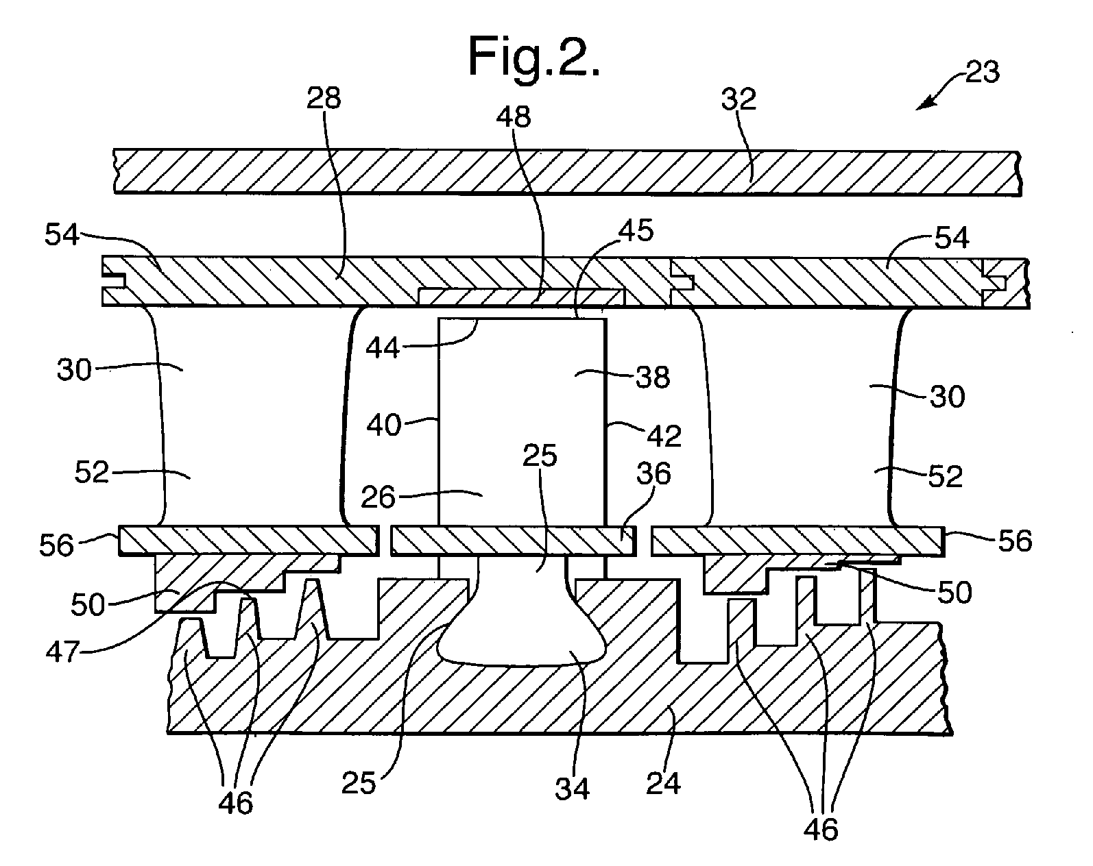
- the high-pressure compressor 23 of the compressor section 16 is shown more clearly in figure 2.
- the high-pressure compressor 23 comprises one or more stages of compressor rotor blades 26 arranged alternately with one or more stages of compressor stator vanes 30.
- Each of the compressor rotor blades 26 comprises a root 34, a shank 25, a platform 36 and an aerofoil 38.
- the compressor rotor blades 26 are arranged circumferentially around a compressor rotor 24 and the compressor rotor blades 26 extend generally radially from the compressor rotor 24.
- the roots 34 of the compressor rotor blades 26 are located in circumferentially, or axially, extending slots 25 in the periphery of the compressor rotor 24.
- the platforms 36 of the compressor rotor blades 26 together define the inner boundary of a portion of the flow path through the high-pressure compressor 23.
- the aerofoils 38 of the compressor rotor blades 26 have leading edges 40, trailing edges 42 and tips 44 at their radially outer extremities.
- compressor rotor blades 26 are integral with the compressor rotor 24 and are either machined from a solid disc of metal or are friction welded, electron beam welded or electron beam welded to the compressor rotor 24.
- the compressor stator vanes 30 also comprise aerofoils 52, which have platforms 56 at their radially inner ends and shrouds 54 at their radially outer ends.
- the stator vanes 30 are also arranged circumferentially around the stator and extend generally radially.
- the shrouds 54 of the compressor stator vanes 30 are secured together to form a stator casing 28.
- a further outer stator casing 32 surrounds the stator casing 28.
- the compressor rotor 24 also comprises one or more sealing fins 46, which extend generally radially outwardly from the compressor rotor 24 towards the platforms 56 of the stator vanes 30 to form a labyrinth seal.
- a small gap, or clearance, 45 is provided radially between the tips 44 of the compressor rotor blades 26 and the compressor casing 28.
- the compressor casing 28 is provided with a seal 48, an abradable coating, on its inner surface immediately around the tips 44 of the compressor rotor blades 26.
- seals 48 are provided around each of the stages of the compressor rotor blades 26, between the tips 44 of the compressor rotor blades 26 and the stator casing 28.
- the seals 48 are carried on the shrouds 54 of the stator vanes 30.
- the seals 48 comprise an abradable material on the shrouds 54 of the stator vanes 30 of the stator casing 28.
- a small gap, or clearance, 47 is provided radially between the tips of the sealing fins 46 and the platforms 56 of the stator vanes 30.
- the platforms 56 of the stator vanes 30 are provided with a seal 50, an abradable coating, on their inner surfaces immediately around the tips of the sealing fins 46.
- the seals 50 are provided between the sealing fins 46 of the compressor rotor 24 and the platforms 56 of the stator vanes 30.
- the seals 50 are carried on the platforms 56 of the stator vanes 30.
- the seals 50 comprise an abradable material on the platforms 56 of the stator vanes 30.
- the abradable material of the seals 48 and 50 comprises an open cell metallic foam 60 and polymeric films 64 closing the cells 62 of the metallic foam 60.
- the abradable material of the seals 48 and 50 is manufactured by providing open cell metallic foam 60.
- the open cell metallic foam 60 preferably comprises nickel foam or nickel alloy foam (Incofoam RTM) and is manufactured in the usual manner, but other suitable metallic foams may be used.
- the resultant metallic foam 60 is highly porous and gas permeable.
- the open cell metallic foam 60 is dipped in a low viscosity, high surface tension, molten polymer. Suitable polymers for use at lower temperatures are polyethylene or polypropylene, in the lower pressure stages of the compressor, or PTFE or PVC in the higher pressure stages of the compressor.
- the metallic foam 60 is removed from the molten polymer and the excess polymer is allowed to drain from the metallic foam 60 to leave thin polymeric film 64 between the metallic matrix 66 of the metallic foam 60.
- the thickness and the number of the thin polymeric films 64 within the metallic foam 60 are controlled by the viscosity of the molten polymer.
- the resultant structure comprises metallic foam 60 and thin polymeric films 64, which close the open cells 62 of the metallic foam 60.
- the thin polymeric films 64 provide limited or no gas permeability.
- the polymer does not fill the pores/cells 62 within the metallic foam 60 and therefore the resultant structure is deformable and abradable.
- the abradable material 50 comprising open cell metallic foam 60 and polymeric films 64 closing the cells 62 of the metallic foam 60 by spraying or painting liquid polymeric material onto the open cell metallic foam 60.
- the advantage of the present invention is that it combines the sealing properties of a closed cell metallic foam structure with the abradability and manufacturing control of an open cell metallic foam structure.
- the abradable material may be used between any relatively rotating members where a good fluid seal, e.g. air or liquid seal, is required up to the operational temperature of the polymer.
- a good fluid seal e.g. air or liquid seal
- the present invention may also be used between other relatively movable members.
Landscapes
- Engineering & Computer Science (AREA)
- General Engineering & Computer Science (AREA)
- Mechanical Engineering (AREA)
- Structures Of Non-Positive Displacement Pumps (AREA)
- Turbine Rotor Nozzle Sealing (AREA)
Abstract
Description
- The present invention relates to a seal between relatively movable members, preferably between first and second relatively rotatable members, in particular a rotor and a stator, more particularly to a seal between a compressor rotor blade and a compressor casing of a turbomachine, for example a gas turbine engine.
- A compressor of a gas turbine engine comprises one or more stages of compressor rotor blades arranged alternately with one or more stages of compressor stator vanes. Each of the compressor rotor blades comprises a root, a shank, a platform and an aerofoil. The compressor rotor blades are arranged circumferentially around a compressor rotor and the compressor rotor blades extend generally radially from the compressor rotor. The roots of the compressor rotor blades are located in axially, or circumferentially, extending slots in the periphery of a compressor rotor. The platforms of the compressor rotor blades together define the inner boundary of a portion of the flow path through the compressor. In an alternative arrangement the compressor rotor blades are integral with the compressor rotor and are either machined from a solid disc of metal or are friction welded, electron beam welded or electron beam welded to the compressor rotor.
- The compressor rotor and the compressor rotor blades are surrounded by a compressor casing. A small gap, or clearance, is provided radially between the tips of the compressor rotor blades and the compressor casing. The compressor casing is provided with an abradable coating on its inner surface immediately around the tips of the compressor rotor blades. These abradable coatings wear preferentially relative to the material of the tips of the compressor rotor blades during engine service. The abradable coatings reduce over tip leakage between the tips of the compressor blades and the compressor casing and hence reduce the associated loss in engine efficiency and engine performance.
- These abradable coatings generally comprise open, or closed, metallic foams. None of these metallic foams have an optimum combination of properties for an abradable coating to form a seal to reduce over tip leakage between the tips of the compressor blades and the compressor casing. Closed cell metallic foams provide excellent sealing capability, but are abrasive to the material of the blade tips due to their increased density. Closed cell metallic foams are also poorly controlled during manufacture, in terms of pore size and distribution within the metallic matrix, and this makes it difficult to predict abradability and the risk of titanium fire due to excessive wear of the blade tips of the compressor blades.
- Accordingly the present invention seeks to provide a novel seal between relatively movable members, which reduces, preferably overcomes, the above-mentioned problem.
- Accordingly the present invention provides a seal between first and second relatively movable members, the seal comprising an abradable material on at least one of the relatively movable members, the abradable material comprising an open cell metallic foam and polymeric films closing the cells of the metallic foam.
- Preferably the first and second members are relatively rotatable members.
- Preferably the first member is a rotor and the second member is a stator, the seal comprising an abradable material on at least one of the rotor and the stator.
- Preferably the rotor comprises a plurality of rotor blades, the stator comprises a casing and the abradable material is arranged on the casing.
- Alternatively the stator comprises a plurality of stator vanes and the abradable material is arranged on the stator vanes.
- Preferably the rotor comprises a compressor rotor, the rotor blades are compressor blades and the casing is a compressor casing.
- Preferably the rotor is a rotor of a gas turbine engine.
- Alternatively the rotor and the stator are a rotor and a stator of a bearing.
- Preferably the open cell metallic foam comprises nickel foam or nickel alloy foam.
- Preferably the polymeric films comprise polyethylene, polypropylene, PTFE or PVC.
- The present invention also provides a method of manufacturing a seal comprising forming an open cell metallic foam, dipping the open cell metallic foam in a molten polymer, removing the open cell metallic foam from the molten polymer, allowing excess molten polymer to drain from the open cell metallic foam to form thin polymeric films which close the cells of the metallic foam.
- Preferably the open cell metallic foam comprises nickel foam or nickel alloy foam.
- Preferably the polymer comprises polyethylene, polypropylene, PTFE or PVC.
- The present invention will be more fully described by way of example with reference to the accompanying drawings in which:-
- Figure 1 shows a turbofan gas turbine engine having a seal between a rotor and a stator according to the present invention.
- Figure 2 shows is an enlarged view of a seal between a rotor blade and a stator casing and a seal between a stator vane and a rotor according to the present invention.
- Figure 3 shows is a further enlarged view of a seal between the rotor blade and a stator casing according to the present invention.
- A turbofan
gas turbine engine 10, as shown in figure 1, comprises in axial flow series anintake 12, a fan section 14, acompressor section 16, acombustion section 18, aturbine section 20 and acore exhaust 22. Theturbine section 20 comprises a high-pressure turbine (not shown) arranged to drive a high-pressure compressor 23 in thecompressor section 16, an intermediate pressure turbine (not shown) arranged to drive an intermediate pressure compressor (not shown) in thecompressor section 16 and a low pressure turbine (not shown) arranged to drive a fan (not shown) in the fan section 14. - The high-
pressure compressor 23 of thecompressor section 16 is shown more clearly in figure 2. The high-pressure compressor 23 comprises one or more stages ofcompressor rotor blades 26 arranged alternately with one or more stages ofcompressor stator vanes 30. Each of thecompressor rotor blades 26 comprises aroot 34, ashank 25, aplatform 36 and anaerofoil 38. Thecompressor rotor blades 26 are arranged circumferentially around acompressor rotor 24 and thecompressor rotor blades 26 extend generally radially from thecompressor rotor 24. Theroots 34 of thecompressor rotor blades 26 are located in circumferentially, or axially, extendingslots 25 in the periphery of thecompressor rotor 24. Theplatforms 36 of thecompressor rotor blades 26 together define the inner boundary of a portion of the flow path through the high-pressure compressor 23. Theaerofoils 38 of thecompressor rotor blades 26 have leadingedges 40,trailing edges 42 andtips 44 at their radially outer extremities. - Alternatively the
compressor rotor blades 26 are integral with thecompressor rotor 24 and are either machined from a solid disc of metal or are friction welded, electron beam welded or electron beam welded to thecompressor rotor 24. - The
compressor stator vanes 30 also compriseaerofoils 52, which haveplatforms 56 at their radially inner ends andshrouds 54 at their radially outer ends. Thestator vanes 30 are also arranged circumferentially around the stator and extend generally radially. Theshrouds 54 of thecompressor stator vanes 30 are secured together to form astator casing 28. A furtherouter stator casing 32 surrounds thestator casing 28. - The
compressor rotor 24 also comprises one or more sealingfins 46, which extend generally radially outwardly from thecompressor rotor 24 towards theplatforms 56 of thestator vanes 30 to form a labyrinth seal. - A small gap, or clearance, 45 is provided radially between the
tips 44 of thecompressor rotor blades 26 and thecompressor casing 28. Thecompressor casing 28 is provided with aseal 48, an abradable coating, on its inner surface immediately around thetips 44 of thecompressor rotor blades 26. - These
seals 48 are provided around each of the stages of thecompressor rotor blades 26, between thetips 44 of thecompressor rotor blades 26 and thestator casing 28. Theseals 48 are carried on theshrouds 54 of thestator vanes 30. Theseals 48 comprise an abradable material on theshrouds 54 of thestator vanes 30 of thestator casing 28. - A small gap, or clearance, 47 is provided radially between the tips of the sealing
fins 46 and theplatforms 56 of thestator vanes 30. Theplatforms 56 of thestator vanes 30 are provided with aseal 50, an abradable coating, on their inner surfaces immediately around the tips of thesealing fins 46. - The
seals 50 are provided between the sealingfins 46 of thecompressor rotor 24 and theplatforms 56 of thestator vanes 30. Theseals 50 are carried on theplatforms 56 of thestator vanes 30. Theseals 50 comprise an abradable material on theplatforms 56 of thestator vanes 30. - The abradable material of the
seals metallic foam 60 andpolymeric films 64 closing thecells 62 of themetallic foam 60. - The abradable material of the
seals metallic foam 60. The open cellmetallic foam 60 preferably comprises nickel foam or nickel alloy foam (Incofoam RTM) and is manufactured in the usual manner, but other suitable metallic foams may be used. The resultantmetallic foam 60 is highly porous and gas permeable. The open cellmetallic foam 60 is dipped in a low viscosity, high surface tension, molten polymer. Suitable polymers for use at lower temperatures are polyethylene or polypropylene, in the lower pressure stages of the compressor, or PTFE or PVC in the higher pressure stages of the compressor. Themetallic foam 60 is removed from the molten polymer and the excess polymer is allowed to drain from themetallic foam 60 to leavethin polymeric film 64 between themetallic matrix 66 of themetallic foam 60. The thickness and the number of the thinpolymeric films 64 within themetallic foam 60 are controlled by the viscosity of the molten polymer. The resultant structure comprisesmetallic foam 60 and thinpolymeric films 64, which close theopen cells 62 of themetallic foam 60. Thus the thinpolymeric films 64 provide limited or no gas permeability. The polymer does not fill the pores/cells 62 within themetallic foam 60 and therefore the resultant structure is deformable and abradable. - It may also be possible to manufacture the
abradable material 50 comprising open cellmetallic foam 60 andpolymeric films 64 closing thecells 62 of themetallic foam 60 by spraying or painting liquid polymeric material onto the open cellmetallic foam 60. - Thus the advantage of the present invention is that it combines the sealing properties of a closed cell metallic foam structure with the abradability and manufacturing control of an open cell metallic foam structure.
- The abradable material may be used between any relatively rotating members where a good fluid seal, e.g. air or liquid seal, is required up to the operational temperature of the polymer.
- Although the present invention has been described with reference to the seal and abradable material being provided on the stator it is equally possible to provide the abradable material on the rotor.
- Although the present invention has been described with reference to a seal between compressor rotor blade tips and a compressor casing and between a rotor and stator vane platforms, it is equally applicable to a seal at other positions between a rotor and a stator of gas turbine engine or a turbomachine and may also be used as a seal between a rotor and a stator of a bearing.
- The present invention may also be used between other relatively movable members.
Claims (13)
- A seal (48, 50) between first and second relatively movable members (24, 26, 28, 30), the seal (48, 50) comprising an abradable material on at least one of the relatively movable members (24, 26, 28, 30), characterised in that the abradable material comprising an open cell metallic foam (60) and polymeric films (64) closing the cells (62) of the metallic foam (60).
- A seal as claimed in claim 1 wherein the first and second members (24, 26, 28, 30) are relatively rotatable members.
- A seal as claimed in claim 2 wherein the first member (24, 26) is a rotor and the second member (28, 30) is a stator, the seal (48) comprising an abradable material on at least one of the rotor (24, 26) and the stator (28, 30).
- A seal as claimed in claim 3 wherein the rotor (24) comprises a plurality of rotor blades (26), the stator comprises a casing (28) and the abradable material is arranged on the casing (28).
- A seal as claimed in claim 3 wherein the stator (28, 30) comprises a plurality of stator vanes (30) and the abradable material is arranged on the stator (30).
- A seal as claimed in claim 4 wherein the rotor (24) comprises a compressor rotor, the rotor blades (26) are compressor blades and the casing (28) is a compressor casing.
- A seal as claimed in any of claims 3 to 6 wherein the rotor (24) is a rotor of a gas turbine engine (10).
- A seal as claimed in claim 3 wherein the rotor and the stator are a rotor and a stator of a bearing.
- A seal as claimed in any of claims 1 to 8 wherein the open cell metallic foam (60) comprises nickel foam or nickel alloy foam.
- A seal as claimed in any of claims 1 to 9 wherein the polymeric films (64) comprise polyethylene, polypropylene, PTFE or PVC.
- A method of manufacturing a seal (48, 50) comprising forming an open cell metallic foam (60), dipping the open cell metallic foam (60) in a molten polymer, removing the open cell metallic foam (60) from the molten polymer, allowing excess molten polymer to drain from the open cell metallic foam (60) to form thin polymeric films (64) which close the cells (62) of the metallic foam (60).
- A method as claimed in claim 11 wherein the open cell metallic foam (60) comprises nickel foam or nickel alloy foam.
- A seal as claimed in claim 11 or claim 12 wherein the polymeric films (64) comprise polyethylene, polypropylene, PTFE or PVC.
Applications Claiming Priority (1)
| Application Number | Priority Date | Filing Date | Title |
|---|---|---|---|
| GBGB0613715.2A GB0613715D0 (en) | 2006-07-11 | 2006-07-11 | A seal between relatively moveable members |
Publications (3)
| Publication Number | Publication Date |
|---|---|
| EP1878876A2 true EP1878876A2 (en) | 2008-01-16 |
| EP1878876A3 EP1878876A3 (en) | 2013-01-16 |
| EP1878876B1 EP1878876B1 (en) | 2013-12-25 |
Family
ID=36955405
Family Applications (1)
| Application Number | Title | Priority Date | Filing Date |
|---|---|---|---|
| EP07252381.4A Active EP1878876B1 (en) | 2006-07-11 | 2007-06-12 | Gas turbine abradable seal and manufacturing method thereof |
Country Status (3)
| Country | Link |
|---|---|
| US (1) | US7955049B2 (en) |
| EP (1) | EP1878876B1 (en) |
| GB (1) | GB0613715D0 (en) |
Cited By (8)
| Publication number | Priority date | Publication date | Assignee | Title |
|---|---|---|---|---|
| EP1967699A1 (en) * | 2007-03-05 | 2008-09-10 | United Technologies Corporation | Gas turbine engine with an abradable seal |
| EP1992419A2 (en) | 2007-03-30 | 2008-11-19 | Nuovo Pignone S.P.A. | Abradable and anti-encrustation coating for rotating fluid machines |
| EP2184449A1 (en) * | 2008-11-05 | 2010-05-12 | Siemens Aktiengesellschaft | Guide vane support, gas turbine and gas or steam turbine engine with such a guide vane support |
| EP2196632A2 (en) | 2008-12-10 | 2010-06-16 | Rolls-Royce plc | A seal in a gas turbine and a method of manufacturing a seal |
| EP2410133A1 (en) * | 2010-07-22 | 2012-01-25 | Siemens Aktiengesellschaft | Gas turbine and method for sealing leakages |
| DE102011014292A1 (en) * | 2011-03-17 | 2012-09-20 | Rolls-Royce Deutschland Ltd & Co Kg | Intermediate level sealing ring for gas turbine engine, is made of metal foam, and has element, which is made of wear-resistant material that is arranged in metal foam, where inner platform is provided for supporting guide vanes |
| US8500397B2 (en) | 2007-12-04 | 2013-08-06 | Hitachi, Ltd. | Seals in steam turbine |
| WO2014055299A1 (en) * | 2012-10-01 | 2014-04-10 | United Technologies Corporation | Aluminum based abradable material with reduced metal transfer to blades |
Families Citing this family (11)
| Publication number | Priority date | Publication date | Assignee | Title |
|---|---|---|---|---|
| DE10348290A1 (en) * | 2003-10-17 | 2005-05-12 | Mtu Aero Engines Gmbh | Sealing arrangement for a gas turbine |
| GB0912796D0 (en) * | 2009-07-23 | 2009-08-26 | Cummins Turbo Tech Ltd | Compressor,turbine and turbocharger |
| US20110120263A1 (en) * | 2009-11-23 | 2011-05-26 | Short Keith E | Porous metal gland seal |
| US9598972B2 (en) * | 2010-03-30 | 2017-03-21 | United Technologies Corporation | Abradable turbine air seal |
| US10247026B2 (en) * | 2013-11-20 | 2019-04-02 | United Technologies Corporation | Erosion resistant coating for air seal |
| US8939707B1 (en) * | 2014-02-25 | 2015-01-27 | Siemens Energy, Inc. | Turbine abradable layer with progressive wear zone terraced ridges |
| US9957826B2 (en) | 2014-06-09 | 2018-05-01 | United Technologies Corporation | Stiffness controlled abradeable seal system with max phase materials and methods of making same |
| DE102018107433A1 (en) * | 2018-03-28 | 2019-10-02 | Rolls-Royce Deutschland Ltd & Co Kg | Inlet lining structure made of a metallic material, method for producing an inlet lining structure and component with an inlet lining structure |
| US11118705B2 (en) | 2018-08-07 | 2021-09-14 | General Electric Company | Quick connect firewall seal for firewall |
| US11513259B1 (en) * | 2019-07-29 | 2022-11-29 | Meta Platforms Technologies, Llc | Gas-soluble nanovoided polymers |
| US11988095B2 (en) * | 2022-03-03 | 2024-05-21 | General Electric Company | Seals for managing thermal distortion in a turbomachine and methods for building the same |
Citations (2)
| Publication number | Priority date | Publication date | Assignee | Title |
|---|---|---|---|---|
| US20010042607A1 (en) | 2000-05-17 | 2001-11-22 | Hans-Joachim Roesler | Process for producing a thermally loaded casting |
| WO2005061855A1 (en) | 2003-12-20 | 2005-07-07 | Mtu Aero Engines Gmbh | Gas turbine component |
Family Cites Families (41)
| Publication number | Priority date | Publication date | Assignee | Title |
|---|---|---|---|---|
| GB851267A (en) | 1958-04-28 | 1960-10-12 | Gen Motors Corp | Improvements relating to axial-flow compressors |
| US4218066A (en) | 1976-03-23 | 1980-08-19 | United Technologies Corporation | Rotary seal |
| DE2755468C2 (en) * | 1977-12-13 | 1985-06-05 | Schott Glaswerke, 6500 Mainz | Process for the production of cadmium stannate layers on substrates, preferably on glass, in a dipping process |
| US4257735A (en) | 1978-12-15 | 1981-03-24 | General Electric Company | Gas turbine engine seal and method for making same |
| GB2081817B (en) * | 1980-08-08 | 1984-02-15 | Rolls Royce | Turbine blade shrouding |
| US4460185A (en) * | 1982-08-23 | 1984-07-17 | General Electric Company | Seal including a non-metallic abradable material |
| US4659082A (en) * | 1982-09-13 | 1987-04-21 | Harold Lorber | Monte verde playing card dispenser |
| DE3579684D1 (en) * | 1984-12-24 | 1990-10-18 | United Technologies Corp | GRINDABLE SEAL WITH SPECIAL EROSION RESISTANCE. |
| US5326633A (en) * | 1986-03-24 | 1994-07-05 | Ensci, Inc. | Coated substrates |
| US4867639A (en) * | 1987-09-22 | 1989-09-19 | Allied-Signal Inc. | Abradable shroud coating |
| US4836553A (en) * | 1988-04-18 | 1989-06-06 | Caribbean Stud Enterprises, Inc. | Poker game |
| US5048833A (en) * | 1990-03-01 | 1991-09-17 | Lamle Steward M | Apparatus for detecting a series of game outcomes |
| US5314304A (en) | 1991-08-15 | 1994-05-24 | The United States Of America As Represented By The Secretary Of The Air Force | Abradeable labyrinth stator seal |
| DE4130946C1 (en) * | 1991-09-18 | 1992-09-03 | Mtu Muenchen Gmbh | |
| US5476259A (en) * | 1992-06-11 | 1995-12-19 | Gamin Weingardt Trust, A Nevada Trust | Pari-mutuel electronic and live table gaming |
| US6019374A (en) * | 1993-02-25 | 2000-02-01 | Shuffle Master, Inc. | Multi-tiered wagering method and game |
| US5362064A (en) * | 1993-09-08 | 1994-11-08 | Richard Lofink | Modified baccarat |
| US5395119A (en) * | 1994-04-08 | 1995-03-07 | Jacob; Douglas P. | Wagering methods for baccarat |
| US6582301B2 (en) * | 1995-10-17 | 2003-06-24 | Smart Shoes, Inc. | System including card game dispensing shoe with barrier and scanner, and enhanced card gaming table, enabling waging by remote bettors |
| US5762552A (en) * | 1995-12-05 | 1998-06-09 | Vt Tech Corp. | Interactive real-time network gaming system |
| US5876283A (en) * | 1997-10-30 | 1999-03-02 | Parra; Anthony C. | Casino progressive baccarat game method of play |
| US6916245B1 (en) * | 1998-04-06 | 2005-07-12 | Mikohn Gaming Corporation | Method for wagering on baccarat tie |
| US5957459A (en) * | 1998-04-27 | 1999-09-28 | Chae; Myung Joo | Banking card game |
| IL127957A (en) * | 1999-01-07 | 2004-12-15 | Yacob Rafaeli | Gambling game system and method for remotely-located players |
| US6283474B1 (en) * | 1999-01-28 | 2001-09-04 | De Keller David Guy | Method for playing a casino game |
| US6460848B1 (en) * | 1999-04-21 | 2002-10-08 | Mindplay Llc | Method and apparatus for monitoring casinos and gaming |
| US6896614B2 (en) * | 1999-11-03 | 2005-05-24 | Baccarat Plus Enterprises, Inc. | Baccarat gaming assembly and method of playing baccarat |
| US6334617B1 (en) * | 2000-03-02 | 2002-01-01 | United Technologies Corporation | Composite abradable material |
| US20020147042A1 (en) * | 2001-02-14 | 2002-10-10 | Vt Tech Corp. | System and method for detecting the result of a game of chance |
| US20030013510A1 (en) * | 2001-06-29 | 2003-01-16 | Vt Tech Corp. | Casino card game |
| US6511072B1 (en) * | 2001-10-22 | 2003-01-28 | Cathy D. Santa Cruz | Card game |
| US6588758B1 (en) * | 2002-02-12 | 2003-07-08 | James C. Lee | Table and method of playing a combination poker and baccarat-type card game |
| US6837494B2 (en) * | 2002-02-12 | 2005-01-04 | James C. Lee | Table and method of playing a baccarat-type card game |
| US20030151199A1 (en) * | 2002-02-12 | 2003-08-14 | Lee James C. | Table and method of playing a baccarat-type card game |
| US6887530B2 (en) * | 2002-06-07 | 2005-05-03 | Sulzer Metco (Canada) Inc. | Thermal spray compositions for abradable seals |
| US7309065B2 (en) * | 2002-12-04 | 2007-12-18 | Shuffle Master, Inc. | Interactive simulated baccarat side bet apparatus and method |
| GB0300999D0 (en) * | 2003-01-16 | 2003-02-19 | Rolls Royce Plc | A gas turbine engine blade containment assembly |
| US7434805B2 (en) * | 2003-07-17 | 2008-10-14 | Shuffle Master, Inc | Intelligent baccarat shoe |
| US7213812B2 (en) * | 2003-07-17 | 2007-05-08 | Shuffle Master, Inc. | Intelligent baccarat shoe |
| US7264241B2 (en) * | 2003-07-17 | 2007-09-04 | Shuffle Master, Inc. | Intelligent baccarat shoe |
| JP2005168664A (en) * | 2003-12-09 | 2005-06-30 | Kenichi Okujo | Baccarat system, usage of baccarat system, baccarat program and recording medium |
-
2006
- 2006-07-11 GB GBGB0613715.2A patent/GB0613715D0/en not_active Ceased
-
2007
- 2007-06-12 EP EP07252381.4A patent/EP1878876B1/en active Active
- 2007-06-13 US US11/808,885 patent/US7955049B2/en active Active
Patent Citations (2)
| Publication number | Priority date | Publication date | Assignee | Title |
|---|---|---|---|---|
| US20010042607A1 (en) | 2000-05-17 | 2001-11-22 | Hans-Joachim Roesler | Process for producing a thermally loaded casting |
| WO2005061855A1 (en) | 2003-12-20 | 2005-07-07 | Mtu Aero Engines Gmbh | Gas turbine component |
Cited By (14)
| Publication number | Priority date | Publication date | Assignee | Title |
|---|---|---|---|---|
| EP1967699A1 (en) * | 2007-03-05 | 2008-09-10 | United Technologies Corporation | Gas turbine engine with an abradable seal |
| US8038388B2 (en) | 2007-03-05 | 2011-10-18 | United Technologies Corporation | Abradable component for a gas turbine engine |
| EP1992419A2 (en) | 2007-03-30 | 2008-11-19 | Nuovo Pignone S.P.A. | Abradable and anti-encrustation coating for rotating fluid machines |
| EP1992419A3 (en) * | 2007-03-30 | 2010-03-03 | Nuovo Pignone S.P.A. | Abradable and anti-encrustation coating for rotating fluid machines |
| US8500397B2 (en) | 2007-12-04 | 2013-08-06 | Hitachi, Ltd. | Seals in steam turbine |
| EP2372103B1 (en) * | 2007-12-04 | 2015-04-15 | Mitsubishi Hitachi Power Systems, Ltd. | Seal structure for a steam turbine |
| EP2184449A1 (en) * | 2008-11-05 | 2010-05-12 | Siemens Aktiengesellschaft | Guide vane support, gas turbine and gas or steam turbine engine with such a guide vane support |
| EP2196632A3 (en) * | 2008-12-10 | 2012-12-05 | Rolls-Royce plc | A seal in a gas turbine and a method of manufacturing a seal |
| US8650753B2 (en) | 2008-12-10 | 2014-02-18 | Rolls-Royce, Plc | Seal and a method of manufacturing a seal |
| EP2196632A2 (en) | 2008-12-10 | 2010-06-16 | Rolls-Royce plc | A seal in a gas turbine and a method of manufacturing a seal |
| EP2410133A1 (en) * | 2010-07-22 | 2012-01-25 | Siemens Aktiengesellschaft | Gas turbine and method for sealing leakages |
| DE102011014292A1 (en) * | 2011-03-17 | 2012-09-20 | Rolls-Royce Deutschland Ltd & Co Kg | Intermediate level sealing ring for gas turbine engine, is made of metal foam, and has element, which is made of wear-resistant material that is arranged in metal foam, where inner platform is provided for supporting guide vanes |
| WO2014055299A1 (en) * | 2012-10-01 | 2014-04-10 | United Technologies Corporation | Aluminum based abradable material with reduced metal transfer to blades |
| US10065243B2 (en) | 2012-10-01 | 2018-09-04 | United Technologies Corporation | Aluminum based abradable material with reduced metal transfer to blades |
Also Published As
| Publication number | Publication date |
|---|---|
| US20080014077A1 (en) | 2008-01-17 |
| US7955049B2 (en) | 2011-06-07 |
| EP1878876A3 (en) | 2013-01-16 |
| GB0613715D0 (en) | 2006-08-23 |
| EP1878876B1 (en) | 2013-12-25 |
Similar Documents
| Publication | Publication Date | Title |
|---|---|---|
| US7955049B2 (en) | Seal between relatively moveable members | |
| EP2196632B1 (en) | A seal in a gas turbine and a method of manufacturing a seal | |
| US9169739B2 (en) | Hybrid blade outer air seal for gas turbine engine | |
| US8016565B2 (en) | Methods and apparatus for assembling gas turbine engines | |
| US7686568B2 (en) | Methods and apparatus for fabricating turbine engines | |
| EP1895108A2 (en) | Angel wing abradable seal and sealing method | |
| EP2564030B1 (en) | Turbine airfoil and method for thermal barrier coating | |
| EP3121382A1 (en) | Gas turbine engines including channel-cooled hooks for retaining a part relative to an engine casing structure | |
| EP2196631A2 (en) | A component having an abrasive layer and a method of applying an abrasive layer on a component | |
| US20100259013A1 (en) | Abradable labyrinth seal for a fluid-flow machine | |
| RU2680169C1 (en) | Double alloy blade | |
| US11105216B2 (en) | Method of manufacturing a component of a turbomachine, component of a turbomachine and turbomachine | |
| WO2013167312A1 (en) | Airfoil arrangement with ptal bond coating and thermal barrier coating, and corresponding manufacturing method | |
| US10215033B2 (en) | Stator seal for turbine rub avoidance | |
| CN101624920B (en) | For the labyrinth seal part of turbo machine dovetail and the method for seal clearance | |
| JP6947851B2 (en) | Turbine blades with skiler tips and high density oxide dispersion reinforcement layers | |
| EP2952341A1 (en) | Blade outer air seal and method of manufacture | |
| WO2012048957A1 (en) | Turbomachine rotor with blade roots with adjusting protrusions | |
| EP3623082A1 (en) | Method of producing an abrasive tip for a turbine blade | |
| US10544699B2 (en) | System and method for minimizing the turbine blade to vane platform overlap gap | |
| Sporer et al. | Ceramics for Abradable shroud seal applications | |
| JP2013209981A (en) | Seal structure and turbine device having the same | |
| EP2662530A1 (en) | Airfoil with MCrAlY coating, corresponding airfoil arrangement and manufacturing method | |
| Dorfman et al. | CERAMICS FOR ABRADABLE SHROUD SEAL APPLICATIONS |
Legal Events
| Date | Code | Title | Description |
|---|---|---|---|
| PUAI | Public reference made under article 153(3) epc to a published international application that has entered the european phase |
Free format text: ORIGINAL CODE: 0009012 |
|
| AK | Designated contracting states |
Kind code of ref document: A2 Designated state(s): AT BE BG CH CY CZ DE DK EE ES FI FR GB GR HU IE IS IT LI LT LU LV MC MT NL PL PT RO SE SI SK TR |
|
| AX | Request for extension of the european patent |
Extension state: AL BA HR MK YU |
|
| PUAL | Search report despatched |
Free format text: ORIGINAL CODE: 0009013 |
|
| AK | Designated contracting states |
Kind code of ref document: A3 Designated state(s): AT BE BG CH CY CZ DE DK EE ES FI FR GB GR HU IE IS IT LI LT LU LV MC MT NL PL PT RO SE SI SK TR |
|
| AX | Request for extension of the european patent |
Extension state: AL BA HR MK RS |
|
| RIC1 | Information provided on ipc code assigned before grant |
Ipc: F16J 15/44 20060101ALI20121210BHEP Ipc: F01D 11/12 20060101AFI20121210BHEP |
|
| 17P | Request for examination filed |
Effective date: 20130507 |
|
| AKX | Designation fees paid |
Designated state(s): DE FR GB |
|
| GRAP | Despatch of communication of intention to grant a patent |
Free format text: ORIGINAL CODE: EPIDOSNIGR1 |
|
| INTG | Intention to grant announced |
Effective date: 20131002 |
|
| GRAS | Grant fee paid |
Free format text: ORIGINAL CODE: EPIDOSNIGR3 |
|
| GRAA | (expected) grant |
Free format text: ORIGINAL CODE: 0009210 |
|
| AK | Designated contracting states |
Kind code of ref document: B1 Designated state(s): DE FR GB |
|
| REG | Reference to a national code |
Ref country code: GB Ref legal event code: FG4D |
|
| REG | Reference to a national code |
Ref country code: DE Ref legal event code: R096 Ref document number: 602007034410 Country of ref document: DE Effective date: 20140213 |
|
| REG | Reference to a national code |
Ref country code: DE Ref legal event code: R097 Ref document number: 602007034410 Country of ref document: DE |
|
| PLBE | No opposition filed within time limit |
Free format text: ORIGINAL CODE: 0009261 |
|
| STAA | Information on the status of an ep patent application or granted ep patent |
Free format text: STATUS: NO OPPOSITION FILED WITHIN TIME LIMIT |
|
| 26N | No opposition filed |
Effective date: 20140926 |
|
| REG | Reference to a national code |
Ref country code: DE Ref legal event code: R097 Ref document number: 602007034410 Country of ref document: DE Effective date: 20140926 |
|
| REG | Reference to a national code |
Ref country code: FR Ref legal event code: PLFP Year of fee payment: 10 |
|
| REG | Reference to a national code |
Ref country code: FR Ref legal event code: CA Effective date: 20170517 |
|
| REG | Reference to a national code |
Ref country code: FR Ref legal event code: PLFP Year of fee payment: 11 |
|
| REG | Reference to a national code |
Ref country code: FR Ref legal event code: PLFP Year of fee payment: 12 |
|
| REG | Reference to a national code |
Ref country code: DE Ref legal event code: R082 Ref document number: 602007034410 Country of ref document: DE Representative=s name: FLEUCHAUS & GALLO PARTNERSCHAFT MBB - PATENT- , DE Ref country code: DE Ref legal event code: R082 Ref document number: 602007034410 Country of ref document: DE Representative=s name: FLEUCHAUS & GALLO PARTNERSCHAFT MBB PATENTANWA, DE |
|
| P01 | Opt-out of the competence of the unified patent court (upc) registered |
Effective date: 20230528 |
|
| PGFP | Annual fee paid to national office [announced via postgrant information from national office to epo] |
Ref country code: FR Payment date: 20230622 Year of fee payment: 17 Ref country code: DE Payment date: 20230627 Year of fee payment: 17 |
|
| PGFP | Annual fee paid to national office [announced via postgrant information from national office to epo] |
Ref country code: GB Payment date: 20230620 Year of fee payment: 17 |