EP1877112B1 - Dispositif medicaux et procedes pour les produire - Google Patents
Dispositif medicaux et procedes pour les produire Download PDFInfo
- Publication number
- EP1877112B1 EP1877112B1 EP06752339A EP06752339A EP1877112B1 EP 1877112 B1 EP1877112 B1 EP 1877112B1 EP 06752339 A EP06752339 A EP 06752339A EP 06752339 A EP06752339 A EP 06752339A EP 1877112 B1 EP1877112 B1 EP 1877112B1
- Authority
- EP
- European Patent Office
- Prior art keywords
- layers
- thickness
- stent
- endoprosthesis
- grains
- Prior art date
- Legal status (The legal status is an assumption and is not a legal conclusion. Google has not performed a legal analysis and makes no representation as to the accuracy of the status listed.)
- Not-in-force
Links
Images


Classifications
-
- A—HUMAN NECESSITIES
- A61—MEDICAL OR VETERINARY SCIENCE; HYGIENE
- A61F—FILTERS IMPLANTABLE INTO BLOOD VESSELS; PROSTHESES; DEVICES PROVIDING PATENCY TO, OR PREVENTING COLLAPSING OF, TUBULAR STRUCTURES OF THE BODY, e.g. STENTS; ORTHOPAEDIC, NURSING OR CONTRACEPTIVE DEVICES; FOMENTATION; TREATMENT OR PROTECTION OF EYES OR EARS; BANDAGES, DRESSINGS OR ABSORBENT PADS; FIRST-AID KITS
- A61F2/00—Filters implantable into blood vessels; Prostheses, i.e. artificial substitutes or replacements for parts of the body; Appliances for connecting them with the body; Devices providing patency to, or preventing collapsing of, tubular structures of the body, e.g. stents
- A61F2/82—Devices providing patency to, or preventing collapsing of, tubular structures of the body, e.g. stents
- A61F2/86—Stents in a form characterised by the wire-like elements; Stents in the form characterised by a net-like or mesh-like structure
- A61F2/90—Stents in a form characterised by the wire-like elements; Stents in the form characterised by a net-like or mesh-like structure characterised by a net-like or mesh-like structure
- A61F2/91—Stents in a form characterised by the wire-like elements; Stents in the form characterised by a net-like or mesh-like structure characterised by a net-like or mesh-like structure made from perforated sheet material or tubes, e.g. perforated by laser cuts or etched holes
- A61F2/915—Stents in a form characterised by the wire-like elements; Stents in the form characterised by a net-like or mesh-like structure characterised by a net-like or mesh-like structure made from perforated sheet material or tubes, e.g. perforated by laser cuts or etched holes with bands having a meander structure, adjacent bands being connected to each other
-
- A—HUMAN NECESSITIES
- A61—MEDICAL OR VETERINARY SCIENCE; HYGIENE
- A61F—FILTERS IMPLANTABLE INTO BLOOD VESSELS; PROSTHESES; DEVICES PROVIDING PATENCY TO, OR PREVENTING COLLAPSING OF, TUBULAR STRUCTURES OF THE BODY, e.g. STENTS; ORTHOPAEDIC, NURSING OR CONTRACEPTIVE DEVICES; FOMENTATION; TREATMENT OR PROTECTION OF EYES OR EARS; BANDAGES, DRESSINGS OR ABSORBENT PADS; FIRST-AID KITS
- A61F2/00—Filters implantable into blood vessels; Prostheses, i.e. artificial substitutes or replacements for parts of the body; Appliances for connecting them with the body; Devices providing patency to, or preventing collapsing of, tubular structures of the body, e.g. stents
- A61F2/82—Devices providing patency to, or preventing collapsing of, tubular structures of the body, e.g. stents
- A61F2/86—Stents in a form characterised by the wire-like elements; Stents in the form characterised by a net-like or mesh-like structure
- A61F2/90—Stents in a form characterised by the wire-like elements; Stents in the form characterised by a net-like or mesh-like structure characterised by a net-like or mesh-like structure
- A61F2/91—Stents in a form characterised by the wire-like elements; Stents in the form characterised by a net-like or mesh-like structure characterised by a net-like or mesh-like structure made from perforated sheet material or tubes, e.g. perforated by laser cuts or etched holes
-
- A—HUMAN NECESSITIES
- A61—MEDICAL OR VETERINARY SCIENCE; HYGIENE
- A61L—METHODS OR APPARATUS FOR STERILISING MATERIALS OR OBJECTS IN GENERAL; DISINFECTION, STERILISATION OR DEODORISATION OF AIR; CHEMICAL ASPECTS OF BANDAGES, DRESSINGS, ABSORBENT PADS OR SURGICAL ARTICLES; MATERIALS FOR BANDAGES, DRESSINGS, ABSORBENT PADS OR SURGICAL ARTICLES
- A61L31/00—Materials for other surgical articles, e.g. stents, stent-grafts, shunts, surgical drapes, guide wires, materials for adhesion prevention, occluding devices, surgical gloves, tissue fixation devices
- A61L31/02—Inorganic materials
- A61L31/022—Metals or alloys
-
- A—HUMAN NECESSITIES
- A61—MEDICAL OR VETERINARY SCIENCE; HYGIENE
- A61F—FILTERS IMPLANTABLE INTO BLOOD VESSELS; PROSTHESES; DEVICES PROVIDING PATENCY TO, OR PREVENTING COLLAPSING OF, TUBULAR STRUCTURES OF THE BODY, e.g. STENTS; ORTHOPAEDIC, NURSING OR CONTRACEPTIVE DEVICES; FOMENTATION; TREATMENT OR PROTECTION OF EYES OR EARS; BANDAGES, DRESSINGS OR ABSORBENT PADS; FIRST-AID KITS
- A61F2/00—Filters implantable into blood vessels; Prostheses, i.e. artificial substitutes or replacements for parts of the body; Appliances for connecting them with the body; Devices providing patency to, or preventing collapsing of, tubular structures of the body, e.g. stents
- A61F2/0077—Special surfaces of prostheses, e.g. for improving ingrowth
-
- A—HUMAN NECESSITIES
- A61—MEDICAL OR VETERINARY SCIENCE; HYGIENE
- A61F—FILTERS IMPLANTABLE INTO BLOOD VESSELS; PROSTHESES; DEVICES PROVIDING PATENCY TO, OR PREVENTING COLLAPSING OF, TUBULAR STRUCTURES OF THE BODY, e.g. STENTS; ORTHOPAEDIC, NURSING OR CONTRACEPTIVE DEVICES; FOMENTATION; TREATMENT OR PROTECTION OF EYES OR EARS; BANDAGES, DRESSINGS OR ABSORBENT PADS; FIRST-AID KITS
- A61F2/00—Filters implantable into blood vessels; Prostheses, i.e. artificial substitutes or replacements for parts of the body; Appliances for connecting them with the body; Devices providing patency to, or preventing collapsing of, tubular structures of the body, e.g. stents
- A61F2/82—Devices providing patency to, or preventing collapsing of, tubular structures of the body, e.g. stents
- A61F2/86—Stents in a form characterised by the wire-like elements; Stents in the form characterised by a net-like or mesh-like structure
- A61F2/90—Stents in a form characterised by the wire-like elements; Stents in the form characterised by a net-like or mesh-like structure characterised by a net-like or mesh-like structure
- A61F2/91—Stents in a form characterised by the wire-like elements; Stents in the form characterised by a net-like or mesh-like structure characterised by a net-like or mesh-like structure made from perforated sheet material or tubes, e.g. perforated by laser cuts or etched holes
- A61F2/915—Stents in a form characterised by the wire-like elements; Stents in the form characterised by a net-like or mesh-like structure characterised by a net-like or mesh-like structure made from perforated sheet material or tubes, e.g. perforated by laser cuts or etched holes with bands having a meander structure, adjacent bands being connected to each other
- A61F2002/91533—Stents in a form characterised by the wire-like elements; Stents in the form characterised by a net-like or mesh-like structure characterised by a net-like or mesh-like structure made from perforated sheet material or tubes, e.g. perforated by laser cuts or etched holes with bands having a meander structure, adjacent bands being connected to each other characterised by the phase between adjacent bands
-
- A—HUMAN NECESSITIES
- A61—MEDICAL OR VETERINARY SCIENCE; HYGIENE
- A61F—FILTERS IMPLANTABLE INTO BLOOD VESSELS; PROSTHESES; DEVICES PROVIDING PATENCY TO, OR PREVENTING COLLAPSING OF, TUBULAR STRUCTURES OF THE BODY, e.g. STENTS; ORTHOPAEDIC, NURSING OR CONTRACEPTIVE DEVICES; FOMENTATION; TREATMENT OR PROTECTION OF EYES OR EARS; BANDAGES, DRESSINGS OR ABSORBENT PADS; FIRST-AID KITS
- A61F2/00—Filters implantable into blood vessels; Prostheses, i.e. artificial substitutes or replacements for parts of the body; Appliances for connecting them with the body; Devices providing patency to, or preventing collapsing of, tubular structures of the body, e.g. stents
- A61F2/82—Devices providing patency to, or preventing collapsing of, tubular structures of the body, e.g. stents
- A61F2/86—Stents in a form characterised by the wire-like elements; Stents in the form characterised by a net-like or mesh-like structure
- A61F2/90—Stents in a form characterised by the wire-like elements; Stents in the form characterised by a net-like or mesh-like structure characterised by a net-like or mesh-like structure
- A61F2/91—Stents in a form characterised by the wire-like elements; Stents in the form characterised by a net-like or mesh-like structure characterised by a net-like or mesh-like structure made from perforated sheet material or tubes, e.g. perforated by laser cuts or etched holes
- A61F2/915—Stents in a form characterised by the wire-like elements; Stents in the form characterised by a net-like or mesh-like structure characterised by a net-like or mesh-like structure made from perforated sheet material or tubes, e.g. perforated by laser cuts or etched holes with bands having a meander structure, adjacent bands being connected to each other
- A61F2002/9155—Adjacent bands being connected to each other
- A61F2002/91575—Adjacent bands being connected to each other connected peak to trough
-
- A—HUMAN NECESSITIES
- A61—MEDICAL OR VETERINARY SCIENCE; HYGIENE
- A61F—FILTERS IMPLANTABLE INTO BLOOD VESSELS; PROSTHESES; DEVICES PROVIDING PATENCY TO, OR PREVENTING COLLAPSING OF, TUBULAR STRUCTURES OF THE BODY, e.g. STENTS; ORTHOPAEDIC, NURSING OR CONTRACEPTIVE DEVICES; FOMENTATION; TREATMENT OR PROTECTION OF EYES OR EARS; BANDAGES, DRESSINGS OR ABSORBENT PADS; FIRST-AID KITS
- A61F2230/00—Geometry of prostheses classified in groups A61F2/00 - A61F2/26 or A61F2/82 or A61F9/00 or A61F11/00 or subgroups thereof
- A61F2230/0002—Two-dimensional shapes, e.g. cross-sections
- A61F2230/0028—Shapes in the form of latin or greek characters
- A61F2230/0054—V-shaped
Definitions
- the invention relates to medical devices, such as stents, and methods of making the devices.
- the body includes various passageways such as arteries, other blood vessels, and other body lumens. These passageways sometimes become occluded or weakened. For example, the passageways can be occluded by a tumor, restricted by plaque, or weakened by an aneurysm. When this occurs, the passageway can be reopened or reinforced, or even replaced, with a medical endoprosthesis.
- An endoprosthesis is typically a tubular member that is placed in a lumen in the body. Examples of endoprostheses include stents, covered stents, and stent-grafts.
- Endoprostheses can be delivered inside the body by a catheter that supports the endoprosthesis in a compacted or reduced-size form as the endoprosthesis is transported to a desired site. Upon reaching the site, the endoprosthesis is expanded, for example, so that it can contact the walls of the lumen.
- the expansion mechanism may include forcing the endoprosthesis to expand radially.
- the expansion mechanism can include the catheter carrying a balloon, which carries a balloon-expandable endoprosthesis.
- the balloon can be inflated to deform and to fix the expanded endoprosthesis at a predetermined position in contact with the lumen wall.
- the balloon can then be deflated, and the catheter withdrawn.
- the endoprosthesis is formed of an elastic material that can be reversibly compacted and expanded, e.g., elastically or through a material phase transition.
- the endoprosthesis is restrained in a compacted condition.
- the restraint is removed, for example, by retracting a restraining device such as an outer sheath, enabling the endoprosthesis to self-expand by its own internal elastic restoring force.
- Document US 2004/106982 shows a metallic three layer stent; documents US 2004/000046 , US 2002/010505 , US 6767360 , US 6099561 disclose other endoprosthesys structures comprising multiple layers for enhencing visibility (MRI) and/or biocompatibility.
- MRI enhencing visibility
- the invention relates to medical devices, such as stents, and methods of making the medical devices, as disclosed in the appended claims.
- the invention features an endoprosthesis that includes at least three layers.
- Each of the layers includes approximately one grain or more across a thickness of the layer, and each of the layers has substantially the same composition.
- the invention features a method of making an endoprosthesis.
- the method includes forming a tubular member defining a lumen into the endoprosthesis.
- the tubular member includes at least three layers having substantially the same composition, and each of the layers includes approximately one grain or more across a thickness of the layer.
- the invention features a method of making an endoprosthesis, which includes arranging a plurality of tubes substantially concentrically about one another to form a tubular member that includes multiple layers.
- the tubular member comprises at least three grains across a thickness of the tubular member.
- the method also includes decreasing a thickness of at least one of the layers.
- Embodiments can include one or more of the following features.
- At least some of the grains have an ASTM E112 grain value of at least about six (e.g., about six to about 12).
- At least one of the layers has a thickness of about 0.08 mm or less (e.g., 0.01 mm to 0.08 mm).
- At least one of the layers includes stainless steel, an alloy comprising platinum and stainless steel, niobium, tantalum, titanium, iridium, cobalt, and/or chromium.
- the endoprosthesis further includes a first material disposed between two of the layers, the first material having a different composition than a composition of the two layers.
- the first material is disposed between each of the layers.
- the first material comprises a stainless steel alloy.
- the endoprosthesis further includes multiple bands and connectors.
- At least one of the bands includes multiple layers.
- At least one of the bands has a thickness of 0.01 mm to 0.08 mm.
- the method further includes decreasing a thickness of at least one of the layers.
- the thickness of the at least one of the layers is 0.08 mm or less (e.g., 0.01 mm to 0.08 mm).
- the method includes concentrically arranging a plurality of tubes to form the tubular member.
- the method further includes work hardening the tubular member such that at least some of the grains are reduced in size.
- the method further includes disposing a first material between at least some of the layers, the first material having a different composition than a composition of one of the layers.
- the method includes disposing the first material between each of the layers.
- the method further includes removing portions of the tubular member to form multiple bands and connectors.
- At least one of the connectors has a width of 0.03 mm to 0.3 mm.
- the tubular member comprises at least three layers.
- each of the layers comprises approximately one grain or more across a thickness of the layer.
- At least one of the layers comprises approximately one grain across the thickness of the layer.
- Embodiments may include one or more of the following advantages.
- medical devices such as endoprostheses
- endoprostheses can be made with an arrangement of grains such that the endoprostheses can be thin and strong.
- the endoprostheses therefore, can assume a small profile when compacted, and can be delivered through and implanted within bodily vessels having relatively small diameters.
- the methods of making the devices allow reliable formation of devices having multiple grains across the thickness of the device.
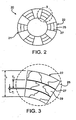
- a stent 20 has the form of a tubular member 21 defined by a plurality of bands 22 and a plurality of connectors 24 that extend between and connect adjacent bands.
- tubular member 21 is a multi-layered structure having multiple layers 25 and multiple interfacial layers 27 (as shown, three layers 25 alternating with two interfacial layers 27).
- layers 25 includes one or more grains 29 across the thickness of the layer. Consequently, tubular member 21 includes multiple grains (as shown, three or more) across its thickness. Without wishing to be bound by theory, it is believed that this grain microstructure can enhance the mechanical properties of stent 20.
- a stent can experience relatively high levels of stress and fatigue.
- the stent can be bent as it tracks through a tortuous vessel during delivery, as it is expanded, and/or when it is placed in a curved vessel.
- the stent can also experience stress from movement caused by a beating heart or by the subject's breathing. The stress can strain the bands and connectors, and can even fracture the bands and/or connectors, for example.
- a fractured band or connector can provide surfaces that disrupt blood flow and/or provide sites on which blood can aggregate and undesirably lead to blood clotting or thrombosis in the vessel.
- the stent By making the stent with a selected grain microstructure (e.g., three or more grains across the thickness of the stent), the fatigue resistance of the stent is enhanced. Consequently, the bands and connectors can better tolerate the stress that can lead to fracture, while still being easily deformable.
- a selected grain microstructure e.g., three or more grains across the thickness of the stent
- the stent is subjected to one or more heat treatment steps that can lead to an unwanted microstructure.
- a heat treatment may lead to a desirable microstructure (such as equiaxed grains)
- the heat treatment can also cause grain growth and a reduction of the number of grains across a thickness of the stent.
- the stent may have an undesired fatigue resistance.
- the grain structure can be controlled, and thus the fatigue resistance of the stent can be improved.
- Layers 25 can include (e.g., can be manufactured from) one or more biocompatible materials with mechanical properties so that stent 20 can be compacted, and subsequently expanded to support a vessel.
- stent 20 can have an ultimate tensile strength (UTS) of 20-160 ksi, greater than about 15% elongation to failure, and a modulus of elasticity of 10-60 msi. When stent 20 is expanded, the material can be stretched to strains on the order of 30 percent.
- UTS ultimate tensile strength
- Examples of materials include stainless steel (e.g., 316L and 304L stainless steel, and an alloy including stainless steel and 5-60% by weight of one or more radiopaque elements (e.g., Pt, Ir, Au, W) (PERSS®) as described in US-2003-0018380-A1 , US-2002-0144757-A1 , and US-2003-0077200-A1 ), Nitinol (a nickel-titanium alloy), Elgiloy, L605 alloys, MP35N, titanium, titanium alloys (e.g., Ti-6A1-4V, Ti-50Ta, Ti-10Ir), platinum, platinum alloys, niobium, niobium alloys (e.g., Nb-IZr) Co-28Cr-6Mo, tantalum, and tantalum alloys.
- radiopaque elements e.g., Pt, Ir, Au, W
- PERSS® radiopaque elements
- Nitinol
- the material(s) can include one or more radiopaque materials to provide radiopacity.
- radiopaque materials include metallic elements having atomic numbers greater than 26 (e.g., greater than 43).
- the radiopaque materials have a density greater than 9.9 g/cc.
- the radiopaque material is relatively absorptive of X-rays, e.g., having a linear attenuation coefficient of at least 25 cm -1 (e.g., at least 50 cm -1 ) at 100 keV.
- radiopaque materials include tantalum, platinum, iridium, palladium, hafnium, tungsten, gold, ruthenium, and rhenium.
- the radiopaque material can include an alloy, such as a binary, a ternary or more complex alloy, containing one or more elements listed above with one or more other elements such as iron, nickel, cobalt, or titanium.
- alloys including one or more radiopaque materials are described in U.S. Application Publication US-2003-0018380-A1 ; US-2002-0144757-A1 ; and US-2003-0077200-A1 .
- stent 20 includes one or more materials that enhance visibility by magnetic resonance imaging (MRI).
- MRI materials include non-ferrous metal-alloys containing paramagnetic elements (e.g., dysprosium or gadolinium) such as terbium-dysprosium, dysprosium, and gadolinium; non-ferrous metallic bands coated with an oxide or a carbide layer of dysprosium or gadolinium (e.g., Dy 2 O 3 or Gd 2 O 3 ); non-ferrous metals (e.g., copper, silver, platinum, or gold) coated with a layer of superparamagnetic material, such as nanocrystalline Fe 3 O 4 , CoFe 2 O 4 , MnFe 2 O 4 , or MgFe 2 O 4 ; and nanocrystalline particles of the transition metal oxides (e.g., oxides of Fe, Co, Ni).
- non-ferrous metal-alloys containing paramagnetic elements e.g., dysprosium or ga
- stent 20 can include one or more materials having low magnetic susceptibility to reduce magnetic susceptibility artifacts, which during imaging can interfere with imaging of tissue adjacent to and/or surrounding the stent, for example.
- Low magnetic susceptibility materials include tantalum, platinum, titanium, niobium, copper, and alloys containing these elements.
- the MRI visible materials can be incorporated into the structural material, can serve as the structural material, and/or be included as a layer of stent 20.
- Layers 25 can each have the same composition, can each have a different compositions, or can have various combinations of compositions.
- the thickness of layer 25 (T 1 ) can be a function of the number of layers 25 in tubular member 21, the composition of layers 25, the targeted mechanical properties, and/or the type of stent.
- thickness (T 1 ) of layer 25 can range from 0.01 mm to 0.08 mm.
- thickness T 1 can be less than or equal to 0.08 mm (e.g., less than or equal to 0.06 mm, less than or equal to 0.04 mm, less than or equal to 0.02 mm).
- Each of layers 25 of a stent can have the same thickness, can have different thicknesses, or can have various combinations of thickness.
- Interfacial layers 27 can include one or more biocompatible materials capable of interrupting grain boundaries between adjacent layers 25.
- Interfacial layers 27, for example, can include any of various materials that are capable of forming a strong bond with adjacent layers, while having a different grain size or structure than the adjacent layers.
- the material(s) of interfacial layers 27 have different grain growth properties than the adjacent layers.
- Interfacial layers 27 can include any of the various materials described above with respect to layers 25.
- the thickness of interfacial layers 27 can be a function of the number of layers 27 in tubular member 21, the composition of layers 27, the targeted mechanical properties, and/or the type of stent.
- thickness (T i ) of layer 27 can range from 0.01 mm to 0.08 mm.
- thickness T i can be less than or equal to 0.08 mm (e.g., less than or equal to 0.06 mm, less than or equal to 0.04 mm, less than or equal to 0.02 mm).
- the thickness of layers 27 of a stent can be the same or different.
- thickness T b can range from 0.05 mm to 0.2 mm.
- thickness T b of bands 22 can be less than or equal to 0.2 mm (e.g., less than or equal to 0.1 mm, less than or equal to 0.08 mm, less than or equal to about 0.06 mm).
- layers 25 and interfacial layers 27 form three or more layers.
- stent 20 can include four or more layers, five or more layers, six or more layers, or seven or more layers.
- stent 20 includes no interfacial layers 27 between adjacent layers 25.
- stent 20 includes multiple interfacial layers 27 between adjacent layers 25.
- Each layer 25 can include one or more grains 29 across its thickness T i .
- the number of grains 29 across stent 20 can be a function of the number of layers 25.
- the number of grains across thickness T b of stent 20 also increases.
- Increasing the number of grains 29 (or layers 25) across thickness T b of stent 20 can increase the fatigue strength of the stent and provide a favorable distribution of the stresses along the stent.
- one or more of the layers has grains 29 with an average ASTM E112 value of from about six to about 12 (the ASTM E112 value being inversely proportional to the average grain diameter).
- ASTM E112 value can be greater than or equal to six, seven, eight, nine, 10, 11, or 12.
- the average grain diameter can range from five microns to 45 microns.
- the average grain diameter can be less than or equal to 45 microns, 40 microns, 35 microns, 30 microns, 25 microns, 20 microns, 15 microns, or ten microns; and/or greater than or equal to five microns, ten microns, 15 microns, 20 microns, 25 microns, 30 microns, 35 microns, or 40 microns.
- the grain size can be fine (e.g., 25 microns or less, 20 microns or less, 15 microns or less, 10 microns or less) to reduce brittleness.
- Fig. 4 shows a method 30 of making stent 20.
- method 30 includes concentrically arranging multiple tubes (step 32) one another.
- the multiple tubes are then drawn down (step 34) to decrease the thickness of the multiple layers.
- a multi-layered tubular member is formed.
- the multi-layered tubular member is heat-treated (step 36) to create a bond (e.g., a diffusion bond) between the multiple layers and to alter the grain structure of the materials from which the layers are formed.
- the multi-layered tubular member is subsequently cut to form bands 22 and connectors 24 (step 38) to produce an unfinished stent. Areas of the unfinished stent affected by the cutting are subsequently removed (step 40).
- the unfinished stent is finished by electropolishing, for example, to form stent 20 (step 42).
- the first step of method 30 includes arranging multiple tubes concentrically about one another (step 32) in order to form the multi-layered tubular member from which stent 20 is made. More specifically, multiple tubes having varying diameters are fitted over one another.
- the tubes for example, can be configured in a "slip-fit" arrangement.
- the tube having the smallest diameter is ultimately positioned at the innermost portion of the resulting tubular member, while the tube having the largest diameter is ultimately positioned at the outermost portion of the tubular member.
- the (inner or outer) diameters of the tubes can range from 0.5 mm to five mm.
- the multiple tubes after processing, become layers 25 of stent 20 (shown in Figs. 2 and 3 ).
- one or more interfacial layers 27 are disposed between adjacent tubes of layers 25.
- Interfacial layer(s) 27 can help to prevent the grains of adjacent tubes from merging during the heat-treatment.
- Interfacial layer(s) 27 can, for example; be one or more additional tubes concentrically arranged within the multi-layered tubular member.
- interfacial layer(s) 27 can be deposited on the tubes using any of various other techniques, such as chemical vapor deposition, physical vapor deposition, and/or sputtering. For example, prior to concentrically arranging the tubes, interfacial layer(s) 27 can be applied to the tubes using one or more of the above-noted techniques.
- interfacial layer(s) 27 is disposed between each of the adjacent tubes.
- multiple interfacial layers 27 e.g., multiple tubes corresponding to interfacial layers 27
- the interface material e.g., the material from which interfacial layer(s) 27 is formed
- the resulting tubular member is processed (e.g., thermomechanically processed) to decrease the thickness of the tubes (step 34).
- the tubular member can be drawn through a series of dies with progressively smaller circular openings to plastically deform the member to a targeted size and shape.
- the thickness of the tubes can be decreased to form multiple layers of a desired thickness.
- the plastic deformation strain hardens the member (and increases its yield strength) and elongates the grains along the longitudinal axis of the member.
- the drawing process can also create a mechanical bond between the adjacent tubes. For example, the relatively high pressure and high temperature experienced during the drawing process can cause the adjacent tubes to bond with one another.
- the steps of arranging the multiple tubes and processing the tubes can be performed in an alternating fashion. For example, two tubes can be concentrically arranged about one another and then processed. Subsequently, a third tube can be arranged concentrically about the processed tubes to form a three-layer tubular member, which can then be processed. This alternating procedure can be repeated until a tubular member having a desired number of layers is achieved.
- the tubular member can be heat-treated to change its microstructure (step 36).
- the tubular member can be annealed above the recrystallization temperature and/or hot isostatically pressed to transform the elongated grain structure into an initial grain structure, e.g., one including equiaxed grains.
- Small or fine grains can be formed by heating the member close to the recrystallization temperature for a relatively short time.
- Large or coarse grains can be formed by heating the member at higher temperatures and/or for longer times to promote grain growth.
- grains have the tendency to grow and to merge with one another, but by using interfacial layer(s) 27, the grains of adjacent tubes can be prevented from merging with one another.
- Grains of the respective layers can, for example, grow substantially independently of one another. As a result, multiple layers and multiple grains can be maintained throughout the heat-treatment, and the fatigue strength of the tubular member can be enhanced.
- thermomechanical processing step (step 34) and the heat-treating step (step 36) can be repeated until the tubular member has a desired thickness and grain structure. In some embodiments, these steps are performed two (e.g., three, four, five, ten) times or more.
- the tubular member can be heat-treated prior to completely forming the multi-layered tubular member.
- the partially formed tubular member can be heat-treated between one or more of the tube-arranging steps and the processing steps.
- the tubes can be heat-treated prior to being concentrically arranged to form the multi-layered tubular member.
- one or more portions of the tubular member can be selectively masked prior to the heat-treatment in order to produce varying grain structures across the stent.
- the stent can include regions of varying physical properties, such as strength, rigidity, and ductility.
- selected portions of the tubular member can be coated with a polished and reflective coating (e.g., on the connectors) and/or a blackened coating (e.g., on the bands).
- the polished and reflective coating such as gold, platinum, and/or silver
- the blackened coating (such as graphite) can increase the amount of heat transferred to the tubular member.
- bands 22 and connectors 24 of multi-layered stent 20 are formed, as shown, by cutting the tube (step 38).
- selected portions of the tube can be removed to form bands 22 and connectors 24 by laser cutting, as described in U.S. Patent No. 5,780,807 .
- a liquid carrier such as a solvent or an oil
- the carrier can prevent dross formed on one portion of the tube from re-depositing on another portion, and/or reduce formation of recast material on the tube.
- other methods of removing portions of the tube can be used, such as mechanical machining (e.g., micro-machining), electrical discharge machining (EDM), and photoetching (e.g., acid photoetching).
- bands 22 and connectors 24 are formed, areas of the multi-layered tube affected by the cutting operation above can be removed (step 40). For example, laser machining of bands 22 and connectors 24 can leave a surface layer of melted and resolidified material and/or oxidized metal that can adversely affect the mechanical properties and performance of multi-layered stent 20. The affected areas can be removed mechanically (such as by grit blasting or honing) and/or chemically (such as by etching or electropolishing).
- the tubular member can be near-net size after step 36 is performed. "Near-net size" means that the tube has a relatively thin envelope of material that is removed to provide a finished stent. In some embodiments, the tube is formed less than 25% oversized, e.g., less than 15%, 10%, or 5% oversized.
- the unfinished stent is then finished (step 42) to form stent 20.
- the unfinished stent can be finished, for example, by electropolishing to a smooth finish. Since the unfinished stent can be formed to near-net size, relatively little of the unfinished stent needs to be removed to finish the stent. As a result, further processing (which can damage the stent) and costly materials can be reduced. In some embodiments, 0.0025 mm of the stent material can be removed by chemical milling and/or electropolishing to yield a stent.
- Stent 20 can be of any desired shape and size (e.g., coronary stents, aortic stents, peripheral vascular stents, gastrointestinal stents, urology stents, and neurology stents).
- stent 20 can have a diameter of one mm to 46 mm.
- a coronary stent can have an expanded diameter of from two mm to six mm.
- a peripheral stent can have an expanded diameter of from five mm to 24 mm.
- a gastrointestinal and/or urology stent can have an expanded diameter of from six mm to 30 mm.
- a neurology stent can have an expanded diameter of from one mm to 12 mm.
- An abdominal aortic aneurysm (AAA) stent and a thoracic aortic aneurysm (TAA) stent can have a diameter from 20 mm to 46 mm.
- Stent 20 can be balloon-expandable, self-expandable, or a combination of both (e.g., U.S. Patent No. 5,366,504 ).
- stent 20 can be used, e.g., delivered and expanded, using a catheter delivery system.
- Catheter systems are described in, for example, Wang U.S. 5,195,969 , Hamlin U.S. 5,270,086 , and Raeder-Devens, U.S. 6,726,712 .
- Stents and stent delivery are also exemplified by the Radius® or Symbiot® systems, available from Boston Scientific Scimed, Maple Grove, MN.
- connectors 24 can have different dimensions than bands 22 and have a multi-layered construction.
- the width of connectors 24 (W c , shown in Fig. 1 ) can be less than the widths of bands 22 (W b ) to allow the connectors to flex and to conform to a vessel.
- a connector 24 refers to a portion of a stent that extends from a band of the stent, for example, from a first band to an adjacent second band along the length of the stent.
- the connector can include one strut (as shown in Fig. 1 ) or a plurality of struts.
- the connector can extend linearly (e.g., parallel to the longitudinal axis of the stent) or nonlinearly, for example, in an undulating patter or zigzag pattern.
- a band 22 refers to a portion of a stent that extends circumferentially about the stent.
- the band can extend completely about the circumference of a stent, for example, such that the ends of the band are joined, or the band can extend partially about the circumference.
- the band can extend substantially linearly or nonlinearly, for example, in an undulating pattern or a zigzag pattern as shown in Figs. 1A and 1B .
- bands 22 are connected together by integrally formed connectors that extend between and transversely to the bands.
- Some examples of dimensions for bands 22 are disclosed in commonly assigned U.S.S.N. 10/961,289, filed October 8, 2004 , and entitled “Medical Devices and Methods of Making the Same".
- the width W c of connector 24 ranges from 0.030 mm to 0.3 mm.
- Particular widths of connector 24 can be a function of the material(s) in stent 20, the type of stent and/or the desired performance.
- connector width W c of a stent including 316L stainless steel can range from 0.05 mm to 0.2 mm;
- connector width W c of a stent including a PERSS® alloy can range from 0.03 mm to 0.18 mm;
- connector width W c of a stent including an alloy having chromium and cobalt can range from 0.02 mm to 0.16 mm;
- connector width W c of a stent including a refractory metal can range from 0.08 mm to 0.30 mm; and connector width W c of a stent including an alloy having titanium can range from 0.03 mm to 0.15 mm.
- connector 24 includes one or more grains across width W c .
- connector 24 can have at least three grains (e.g., at least four grains, at least five grains, or at least six grains) across width W c .
- connector 24 has an average ASTM E112 grain size of about six or smaller. The average grain diameter, for example, can range from five microns to 45 microns.
- the average grain diameter can be equal to or less than 45 microns, 40 microns, 35 microns, 30 microns, 25 microns, 20 microns, 15 microns, or ten microns; and/or greater than or equal to five microns, ten microns, 15 microns, 20 microns, 25 microns, 30 microns, 35 microns, or 40 microns.
- the grain size can be fine (e.g., less than or equal to 25 microns, 20 microns, 15 microns, or ten microns) to reduce brittleness.
- connector 24 can include multiple grains (e.g., three or more) across a thickness T c (shown in Fig. 1 ) of connector 24 as described above for tubular member 21.
- stent 20 includes at least one layer of a softer material and at least one layer of a harder material.
- a layer formed of a soft malleable material can be positioned adjacent a layer formed of a higher strength material. Consequently, recoil of the stent, which can cause problems among stents formed of high strength materials, can be reduced.
- Stent 20 can also be a part of a covered stent or a stent-graft.
- stent 20 can include and/or be attached to a biocompatible, non-porous or semi-porous polymer matrix made of polytetrafluoroethylene (PTFE), expanded PTFE, polyethylene, urethane, or polypropylene.
- PTFE polytetrafluoroethylene
- expanded PTFE polyethylene
- urethane polypropylene
- Stent 20 can include a releasable therapeutic agent, drug, or a pharmaceutically active compound, such as described in U.S. Patent No. 5,674,242 , U.S.S.N. 09/895,415, filed July 2,2001 , and U.S.S.N. 10/232,265, filed August 30, 2002 .
- the therapeutic agents, drugs, or pharmaceutically active compounds can include, for example, anti-thrombogenic agents, antioxidants, anti-inflammatory agents, anesthetic agents, anti-coagulants, and antibiotics.
- the structures and methods described herein can be used to make other medical devices.
- the structures and methods described herein can be used to make devices, such as hypotube catheter shafts and/or guide wires.
Landscapes
- Health & Medical Sciences (AREA)
- Engineering & Computer Science (AREA)
- Biomedical Technology (AREA)
- Life Sciences & Earth Sciences (AREA)
- Veterinary Medicine (AREA)
- Public Health (AREA)
- General Health & Medical Sciences (AREA)
- Animal Behavior & Ethology (AREA)
- Heart & Thoracic Surgery (AREA)
- Vascular Medicine (AREA)
- Cardiology (AREA)
- Transplantation (AREA)
- Oral & Maxillofacial Surgery (AREA)
- Physics & Mathematics (AREA)
- Optics & Photonics (AREA)
- Chemical & Material Sciences (AREA)
- Inorganic Chemistry (AREA)
- Surgery (AREA)
- Epidemiology (AREA)
- Materials For Medical Uses (AREA)
- Media Introduction/Drainage Providing Device (AREA)
- Prostheses (AREA)
Claims (25)
- Endoprothèse comportant au moins trois couches (25), chacune des couches comportant un ou plusieurs grains (29) dans une épaisseur de la couche (25), caractérisée en ce que les couches ont sensiblement la même composition, et en ce qu'une couche interfaciale (27) est disposée entre chacune des couches (25) pour empêcher les grains des couches adjacentes de fusionner les uns avec les autres, dans laquelle au moins une des couches comprend de l'acier inoxydable, un alliage comportant du platine et de l'acier inoxydable, du niobium, du tantale, du titane, de l'iridium, du cobalt, et/ou du chrome.
- Endoprothèse selon la revendication 1, dans laquelle au moins certains des grains (29) ont un indice de grains selon la norme ASTM E1 12 d'au moins 6.
- Endoprothèse selon la revendication 1, dans laquelle au moins certains des grains (29) ont un indice de grains selon la norme ASTM E1 12 de 6 à 12.
- Endoprothèse selon la revendication 1, dans laquelle au moins une des couches (25) a une épaisseur de 0,08 mm ou moins.
- Endoprothèse selon la revendication 4, dans laquelle l'épaisseur de ladite au moins une des couches (25) est de 0,01 mm à 0,08 mm
- Endoprothèse selon la revendication 1, dans laquelle la couche interfaciale (27) comporte un premier matériau dont la composition est différente d'une composition des deux couches.
- Endoprothèse selon la revendication 6, dans laquelle ledit premier matériau comprend un ou plusieurs matériaux biocompatibles pouvant interrompre les joints de grains entre les couches adjacentes (25).
- Endoprothèse selon la revendication 6, dans laquelle le premier matériau comporte un alliage d'acier inoxydable.
- Endoprothèse selon la revendication 1, comportant en outre une pluralité de bandes (22) et de connecteurs (24).
- Endoprothèse selon la revendication 9, dans laquelle au moins une des bandes (22) comporte la pluralité de couches (25).
- Endoprothèse selon la revendication 9, dans laquelle au moins une des bandes (22) a une épaisseur de 0,01 mm à 0,08 mm.
- Procédé pour fabriquer une endoprothèse, le procédé consistant à :former un organe tubulaire définissant une lumière dans l'endoprothèse, l'organe tubulaire comportant au moins trois couches (25), chacune des couches comportant un ou plusieurs grains (29) dans une épaisseur de la couche (25), dans lequel au moins une des couches comprend de l'acier inoxydable, un alliage comportant du platine et de l'acier inoxydable, du niobium, du tantale, du titane, de l'iridium, du cobalt, et/ou du chrome ;caractérisé en ce que les couches (25) ont sensiblement la même composition, et en ce que le procédé consiste en outre à disposer une couche interfaciale (27) entre chacune des couches (25) pour empêcher les grains des couches adjacentes de fusionner les uns avec les autres.
- Procédé selon la revendication 12, consistant en outre à faire diminuer l'épaisseur d'au moins une des couches (25).
- Procédé selon la revendication 13, dans lequel après l'étape de diminution de l'épaisseur, l'épaisseur de ladite au moins une des couches (25) est de 0,08 mm ou moins.
- Procédé selon la revendication 13, dans lequel après l'étape de diminution de l'épaisseur, l'épaisseur de ladite au moins une des couches (25) est de 0,01 mm à 0,08 mm
- Procédé selon la revendication 12, consistant à disposer de manière concentrique une pluralité de tubes pour former l'organe tubulaire.
- Procédé selon la revendication 12, dans lequel au moins certains des grains ont un indice de grains selon la norme ASTM E1 12 de 6 ou plus.
- Procédé selon la revendication 17, dans lequel lesdits au moins certains des grains ont un indice de grains selon la norme ASTM E1 12 de 6 à 12.
- Procédé selon la revendication 12, comportant en outre un travail consistant à durcir l'organe tubulaire de sorte que la taille d'au moins certains des grains diminue.
- Procédé selon la revendication 12, dans lequel la couche interfaciale (27) comporte un premier matériau dont la composition est différente d'une composition de l'une des couches.
- Procédé selon la revendication 20, dans lequel ledit premier matériau comprend un ou plusieurs matériaux biocompatibles pouvant interrompre les joints de grains entre les couches adjacentes (25).
- Procédé selon la revendication 12, consistant en outre à enlever des parties de l'organe tubulaire pour former une pluralité de bandes (22) et de connecteurs (24).
- Procédé selon la revendication 22, dans lequel au moins une des bandes (22) a une épaisseur de 0,01 mm à 0,08 mm.
- Procédé selon la revendication 22, dans lequel ladite au moins une des bandes (22) comporte la pluralité de couches (25).
- Procédé selon la revendication 22, dans lequel ledit au moins un des connecteurs (24) a une largeur de 0,03 mm à 0,3 mm.
Applications Claiming Priority (2)
| Application Number | Priority Date | Filing Date | Title |
|---|---|---|---|
| US11/122,819 US20060259126A1 (en) | 2005-05-05 | 2005-05-05 | Medical devices and methods of making the same |
| PCT/US2006/017475 WO2006121890A2 (fr) | 2005-05-05 | 2006-05-04 | Dispositif medicaux et procedes pour les produire |
Publications (2)
| Publication Number | Publication Date |
|---|---|
| EP1877112A2 EP1877112A2 (fr) | 2008-01-16 |
| EP1877112B1 true EP1877112B1 (fr) | 2011-12-28 |
Family
ID=37191375
Family Applications (1)
| Application Number | Title | Priority Date | Filing Date |
|---|---|---|---|
| EP06752339A Not-in-force EP1877112B1 (fr) | 2005-05-05 | 2006-05-04 | Dispositif medicaux et procedes pour les produire |
Country Status (6)
| Country | Link |
|---|---|
| US (1) | US20060259126A1 (fr) |
| EP (1) | EP1877112B1 (fr) |
| JP (1) | JP2008539898A (fr) |
| AT (1) | ATE538819T1 (fr) |
| CA (1) | CA2606546A1 (fr) |
| WO (1) | WO2006121890A2 (fr) |
Families Citing this family (15)
| Publication number | Priority date | Publication date | Assignee | Title |
|---|---|---|---|---|
| US7250058B1 (en) * | 2000-03-24 | 2007-07-31 | Abbott Cardiovascular Systems Inc. | Radiopaque intraluminal stent |
| US7344560B2 (en) * | 2004-10-08 | 2008-03-18 | Boston Scientific Scimed, Inc. | Medical devices and methods of making the same |
| EP1842507B1 (fr) * | 2005-01-28 | 2013-04-24 | Terumo Kabushiki Kaisha | Implant intravasculaire |
| EP2020967B1 (fr) * | 2006-05-12 | 2020-09-23 | Cardinal Health Switzerland 515 GmbH | Endoprothèse à élution de médicament bioabsorbable et expansible par ballonnet |
| US8769794B2 (en) * | 2006-09-21 | 2014-07-08 | Mico Innovations, Llc | Specially configured and surface modified medical device with certain design features that utilize the intrinsic properties of tungsten, zirconium, tantalum and/or niobium |
| US8142490B2 (en) * | 2007-10-24 | 2012-03-27 | Cordis Corporation | Stent segments axially connected by thin film |
| EP2265299B1 (fr) | 2008-04-08 | 2013-03-13 | Cook Medical Technologies LLC | Structure de surface d'un composant d'un dispositif médical et procédé de formation de ladite structure de surface |
| US9119906B2 (en) | 2008-09-24 | 2015-09-01 | Integran Technologies, Inc. | In-vivo biodegradable medical implant |
| JP5713336B2 (ja) * | 2010-08-12 | 2015-05-07 | 株式会社オプトニクス精密 | ステント |
| US11298251B2 (en) | 2010-11-17 | 2022-04-12 | Abbott Cardiovascular Systems, Inc. | Radiopaque intraluminal stents comprising cobalt-based alloys with primarily single-phase supersaturated tungsten content |
| US9566147B2 (en) | 2010-11-17 | 2017-02-14 | Abbott Cardiovascular Systems, Inc. | Radiopaque intraluminal stents comprising cobalt-based alloys containing one or more platinum group metals, refractory metals, or combinations thereof |
| US10300297B2 (en) | 2011-06-17 | 2019-05-28 | Signify Holding B.V. | Light-emitting device and photo-therapy device comprising a light-emitting device |
| US9724494B2 (en) | 2011-06-29 | 2017-08-08 | Abbott Cardiovascular Systems, Inc. | Guide wire device including a solderable linear elastic nickel-titanium distal end section and methods of preparation therefor |
| US20130096669A1 (en) * | 2011-10-12 | 2013-04-18 | Abbott Cardiovascular Systems, Inc. | Partially annealed stent |
| EP2769742A1 (fr) * | 2013-02-22 | 2014-08-27 | Cardiatis S.A. | Dispositif médical visible par IRM |
Family Cites Families (47)
| Publication number | Priority date | Publication date | Assignee | Title |
|---|---|---|---|---|
| SE445884B (sv) * | 1982-04-30 | 1986-07-28 | Medinvent Sa | Anordning for implantation av en rorformig protes |
| US4958625A (en) * | 1989-07-18 | 1990-09-25 | Boston Scientific Corporation | Biopsy needle instrument |
| ATE91638T1 (de) * | 1989-09-25 | 1993-08-15 | Schneider Usa Inc | Mehrschichtextrusion als verfahren zur herstellung von ballons zur gefaessplastik. |
| US5477864A (en) * | 1989-12-21 | 1995-12-26 | Smith & Nephew Richards, Inc. | Cardiovascular guidewire of enhanced biocompatibility |
| US5090419A (en) * | 1990-08-23 | 1992-02-25 | Aubrey Palestrant | Apparatus for acquiring soft tissue biopsy specimens |
| US5195969A (en) * | 1991-04-26 | 1993-03-23 | Boston Scientific Corporation | Co-extruded medical balloons and catheter using such balloons |
| US5366504A (en) * | 1992-05-20 | 1994-11-22 | Boston Scientific Corporation | Tubular medical prosthesis |
| EP0633798B1 (fr) * | 1992-03-31 | 2003-05-07 | Boston Scientific Corporation | Filtre vasculaire |
| US5630840A (en) * | 1993-01-19 | 1997-05-20 | Schneider (Usa) Inc | Clad composite stent |
| ES2166370T3 (es) * | 1993-01-19 | 2002-04-16 | Schneider Usa Inc | Filamento implantable en material compuesto. |
| JP3647456B2 (ja) * | 1994-04-29 | 2005-05-11 | ボストン・サイエンティフィック・コーポレーション | 医療用人工ステント及びその製造方法 |
| CA2301351C (fr) * | 1994-11-28 | 2002-01-22 | Advanced Cardiovascular Systems, Inc. | Methode et appareil pour la coupe directe au laser, d'extenseurs metalliques |
| US6896696B2 (en) * | 1998-11-20 | 2005-05-24 | Scimed Life Systems, Inc. | Flexible and expandable stent |
| US5674242A (en) * | 1995-06-06 | 1997-10-07 | Quanam Medical Corporation | Endoprosthetic device with therapeutic compound |
| US6099561A (en) * | 1996-10-21 | 2000-08-08 | Inflow Dynamics, Inc. | Vascular and endoluminal stents with improved coatings |
| US6387121B1 (en) * | 1996-10-21 | 2002-05-14 | Inflow Dynamics Inc. | Vascular and endoluminal stents with improved coatings |
| US5858556A (en) * | 1997-01-21 | 1999-01-12 | Uti Corporation | Multilayer composite tubular structure and method of making |
| US6569270B2 (en) * | 1997-07-11 | 2003-05-27 | Honeywell International Inc. | Process for producing a metal article |
| US6340367B1 (en) * | 1997-08-01 | 2002-01-22 | Boston Scientific Scimed, Inc. | Radiopaque markers and methods of using the same |
| NO311781B1 (no) * | 1997-11-13 | 2002-01-28 | Medinol Ltd | Flerlags-stenter av metall |
| US6342062B1 (en) * | 1998-09-24 | 2002-01-29 | Scimed Life Systems, Inc. | Retrieval devices for vena cava filter |
| US6245104B1 (en) * | 1999-02-28 | 2001-06-12 | Inflow Dynamics Inc. | Method of fabricating a biocompatible stent |
| US6264595B1 (en) * | 1999-02-04 | 2001-07-24 | Mobeta, Inc. | Radioactive transition metal stents |
| US6171327B1 (en) * | 1999-02-24 | 2001-01-09 | Scimed Life Systems, Inc. | Intravascular filter and method |
| US6620192B1 (en) * | 1999-03-16 | 2003-09-16 | Advanced Cardiovascular Systems, Inc. | Multilayer stent |
| US6726712B1 (en) * | 1999-05-14 | 2004-04-27 | Boston Scientific Scimed | Prosthesis deployment device with translucent distal end |
| US6146404A (en) * | 1999-09-03 | 2000-11-14 | Scimed Life Systems, Inc. | Removable thrombus filter |
| US6379383B1 (en) * | 1999-11-19 | 2002-04-30 | Advanced Bio Prosthetic Surfaces, Ltd. | Endoluminal device exhibiting improved endothelialization and method of manufacture thereof |
| JP2005503178A (ja) * | 2000-01-25 | 2005-02-03 | ボストン サイエンティフィック リミテッド | 蒸着による医療器具の製造 |
| EP1253953A1 (fr) * | 2000-02-09 | 2002-11-06 | Sagittarius AE Ltd. | Dispositifs implantables non thrombogenes |
| US20030018380A1 (en) * | 2000-07-07 | 2003-01-23 | Craig Charles H. | Platinum enhanced alloy and intravascular or implantable medical devices manufactured therefrom |
| US20020144757A1 (en) * | 2000-07-07 | 2002-10-10 | Craig Charles Horace | Stainless steel alloy with improved radiopaque characteristics |
| US20030077200A1 (en) * | 2000-07-07 | 2003-04-24 | Craig Charles H. | Enhanced radiopaque alloy stent |
| US7101391B2 (en) * | 2000-09-18 | 2006-09-05 | Inflow Dynamics Inc. | Primarily niobium stent |
| US6478815B1 (en) * | 2000-09-18 | 2002-11-12 | Inflow Dynamics Inc. | Vascular and endoluminal stents |
| US6767360B1 (en) * | 2001-02-08 | 2004-07-27 | Inflow Dynamics Inc. | Vascular stent with composite structure for magnetic reasonance imaging capabilities |
| US7201940B1 (en) * | 2001-06-12 | 2007-04-10 | Advanced Cardiovascular Systems, Inc. | Method and apparatus for thermal spray processing of medical devices |
| US6676987B2 (en) * | 2001-07-02 | 2004-01-13 | Scimed Life Systems, Inc. | Coating a medical appliance with a bubble jet printing head |
| US8562664B2 (en) * | 2001-10-25 | 2013-10-22 | Advanced Cardiovascular Systems, Inc. | Manufacture of fine-grained material for use in medical devices |
| US7462366B2 (en) * | 2002-03-29 | 2008-12-09 | Boston Scientific Scimed, Inc. | Drug delivery particle |
| US6865810B2 (en) * | 2002-06-27 | 2005-03-15 | Scimed Life Systems, Inc. | Methods of making medical devices |
| US7029495B2 (en) * | 2002-08-28 | 2006-04-18 | Scimed Life Systems, Inc. | Medical devices and methods of making the same |
| US20040143317A1 (en) * | 2003-01-17 | 2004-07-22 | Stinson Jonathan S. | Medical devices |
| EP1444993B2 (fr) * | 2003-02-10 | 2013-06-26 | W.C. Heraeus GmbH | Alliage métallique amélioré pour des articles médicaux et des implants |
| US20050070990A1 (en) * | 2003-09-26 | 2005-03-31 | Stinson Jonathan S. | Medical devices and methods of making same |
| US20050131522A1 (en) * | 2003-12-10 | 2005-06-16 | Stinson Jonathan S. | Medical devices and methods of making the same |
| US7344560B2 (en) * | 2004-10-08 | 2008-03-18 | Boston Scientific Scimed, Inc. | Medical devices and methods of making the same |
-
2005
- 2005-05-05 US US11/122,819 patent/US20060259126A1/en not_active Abandoned
-
2006
- 2006-05-04 AT AT06752339T patent/ATE538819T1/de active
- 2006-05-04 JP JP2008510278A patent/JP2008539898A/ja active Pending
- 2006-05-04 EP EP06752339A patent/EP1877112B1/fr not_active Not-in-force
- 2006-05-04 CA CA002606546A patent/CA2606546A1/fr not_active Abandoned
- 2006-05-04 WO PCT/US2006/017475 patent/WO2006121890A2/fr active Application Filing
Also Published As
| Publication number | Publication date |
|---|---|
| WO2006121890A3 (fr) | 2007-11-08 |
| CA2606546A1 (fr) | 2006-11-16 |
| WO2006121890A2 (fr) | 2006-11-16 |
| US20060259126A1 (en) | 2006-11-16 |
| JP2008539898A (ja) | 2008-11-20 |
| ATE538819T1 (de) | 2012-01-15 |
| EP1877112A2 (fr) | 2008-01-16 |
Similar Documents
| Publication | Publication Date | Title |
|---|---|---|
| EP1877112B1 (fr) | Dispositif medicaux et procedes pour les produire | |
| US7749264B2 (en) | Medical devices and methods of making the same | |
| US8435280B2 (en) | Flexible stent with variable width elements | |
| EP1866006B1 (fr) | Dispositifs medicaux renfermant des composites | |
| US9402936B2 (en) | Medical devices having alloy compositions | |
| JP2008515563A6 (ja) | 医療用装置及びその製造方法 | |
| US20040143317A1 (en) | Medical devices | |
| WO2008063775A2 (fr) | Dispositifs médicaux comprenant des alliages durcis | |
| JP2010532222A (ja) | モリブデン人工器官 | |
| US20080071344A1 (en) | Medical device with porous surface |
Legal Events
| Date | Code | Title | Description |
|---|---|---|---|
| PUAI | Public reference made under article 153(3) epc to a published international application that has entered the european phase |
Free format text: ORIGINAL CODE: 0009012 |
|
| 17P | Request for examination filed |
Effective date: 20071024 |
|
| AK | Designated contracting states |
Kind code of ref document: A2 Designated state(s): AT BE BG CH CY CZ DE DK EE ES FI FR GB GR HU IE IS IT LI LT LU LV MC NL PL PT RO SE SI SK TR |
|
| AX | Request for extension of the european patent |
Extension state: AL BA HR MK YU |
|
| DAX | Request for extension of the european patent (deleted) | ||
| 17Q | First examination report despatched |
Effective date: 20080814 |
|
| GRAP | Despatch of communication of intention to grant a patent |
Free format text: ORIGINAL CODE: EPIDOSNIGR1 |
|
| GRAS | Grant fee paid |
Free format text: ORIGINAL CODE: EPIDOSNIGR3 |
|
| GRAA | (expected) grant |
Free format text: ORIGINAL CODE: 0009210 |
|
| AK | Designated contracting states |
Kind code of ref document: B1 Designated state(s): AT BE BG CH CY CZ DE DK EE ES FI FR GB GR HU IE IS IT LI LT LU LV MC NL PL PT RO SE SI SK TR |
|
| REG | Reference to a national code |
Ref country code: GB Ref legal event code: FG4D |
|
| REG | Reference to a national code |
Ref country code: CH Ref legal event code: EP |
|
| REG | Reference to a national code |
Ref country code: AT Ref legal event code: REF Ref document number: 538819 Country of ref document: AT Kind code of ref document: T Effective date: 20120115 |
|
| REG | Reference to a national code |
Ref country code: IE Ref legal event code: FG4D |
|
| REG | Reference to a national code |
Ref country code: DE Ref legal event code: R096 Ref document number: 602006026711 Country of ref document: DE Effective date: 20120223 |
|
| REG | Reference to a national code |
Ref country code: NL Ref legal event code: VDEP Effective date: 20111228 |
|
| PG25 | Lapsed in a contracting state [announced via postgrant information from national office to epo] |
Ref country code: LT Free format text: LAPSE BECAUSE OF FAILURE TO SUBMIT A TRANSLATION OF THE DESCRIPTION OR TO PAY THE FEE WITHIN THE PRESCRIBED TIME-LIMIT Effective date: 20111228 |
|
| LTIE | Lt: invalidation of european patent or patent extension |
Effective date: 20111228 |
|
| PG25 | Lapsed in a contracting state [announced via postgrant information from national office to epo] |
Ref country code: SI Free format text: LAPSE BECAUSE OF FAILURE TO SUBMIT A TRANSLATION OF THE DESCRIPTION OR TO PAY THE FEE WITHIN THE PRESCRIBED TIME-LIMIT Effective date: 20111228 Ref country code: GR Free format text: LAPSE BECAUSE OF FAILURE TO SUBMIT A TRANSLATION OF THE DESCRIPTION OR TO PAY THE FEE WITHIN THE PRESCRIBED TIME-LIMIT Effective date: 20120329 Ref country code: LV Free format text: LAPSE BECAUSE OF FAILURE TO SUBMIT A TRANSLATION OF THE DESCRIPTION OR TO PAY THE FEE WITHIN THE PRESCRIBED TIME-LIMIT Effective date: 20111228 Ref country code: SE Free format text: LAPSE BECAUSE OF FAILURE TO SUBMIT A TRANSLATION OF THE DESCRIPTION OR TO PAY THE FEE WITHIN THE PRESCRIBED TIME-LIMIT Effective date: 20111228 |
|
| PG25 | Lapsed in a contracting state [announced via postgrant information from national office to epo] |
Ref country code: BE Free format text: LAPSE BECAUSE OF FAILURE TO SUBMIT A TRANSLATION OF THE DESCRIPTION OR TO PAY THE FEE WITHIN THE PRESCRIBED TIME-LIMIT Effective date: 20111228 Ref country code: CY Free format text: LAPSE BECAUSE OF FAILURE TO SUBMIT A TRANSLATION OF THE DESCRIPTION OR TO PAY THE FEE WITHIN THE PRESCRIBED TIME-LIMIT Effective date: 20111228 |
|
| PG25 | Lapsed in a contracting state [announced via postgrant information from national office to epo] |
Ref country code: IS Free format text: LAPSE BECAUSE OF FAILURE TO SUBMIT A TRANSLATION OF THE DESCRIPTION OR TO PAY THE FEE WITHIN THE PRESCRIBED TIME-LIMIT Effective date: 20120428 Ref country code: CZ Free format text: LAPSE BECAUSE OF FAILURE TO SUBMIT A TRANSLATION OF THE DESCRIPTION OR TO PAY THE FEE WITHIN THE PRESCRIBED TIME-LIMIT Effective date: 20111228 Ref country code: NL Free format text: LAPSE BECAUSE OF FAILURE TO SUBMIT A TRANSLATION OF THE DESCRIPTION OR TO PAY THE FEE WITHIN THE PRESCRIBED TIME-LIMIT Effective date: 20111228 Ref country code: EE Free format text: LAPSE BECAUSE OF FAILURE TO SUBMIT A TRANSLATION OF THE DESCRIPTION OR TO PAY THE FEE WITHIN THE PRESCRIBED TIME-LIMIT Effective date: 20111228 Ref country code: SK Free format text: LAPSE BECAUSE OF FAILURE TO SUBMIT A TRANSLATION OF THE DESCRIPTION OR TO PAY THE FEE WITHIN THE PRESCRIBED TIME-LIMIT Effective date: 20111228 Ref country code: BG Free format text: LAPSE BECAUSE OF FAILURE TO SUBMIT A TRANSLATION OF THE DESCRIPTION OR TO PAY THE FEE WITHIN THE PRESCRIBED TIME-LIMIT Effective date: 20120328 |
|
| PG25 | Lapsed in a contracting state [announced via postgrant information from national office to epo] |
Ref country code: PT Free format text: LAPSE BECAUSE OF FAILURE TO SUBMIT A TRANSLATION OF THE DESCRIPTION OR TO PAY THE FEE WITHIN THE PRESCRIBED TIME-LIMIT Effective date: 20120430 Ref country code: RO Free format text: LAPSE BECAUSE OF FAILURE TO SUBMIT A TRANSLATION OF THE DESCRIPTION OR TO PAY THE FEE WITHIN THE PRESCRIBED TIME-LIMIT Effective date: 20111228 Ref country code: PL Free format text: LAPSE BECAUSE OF FAILURE TO SUBMIT A TRANSLATION OF THE DESCRIPTION OR TO PAY THE FEE WITHIN THE PRESCRIBED TIME-LIMIT Effective date: 20111228 |
|
| REG | Reference to a national code |
Ref country code: AT Ref legal event code: MK05 Ref document number: 538819 Country of ref document: AT Kind code of ref document: T Effective date: 20111228 |
|
| PG25 | Lapsed in a contracting state [announced via postgrant information from national office to epo] |
Ref country code: DK Free format text: LAPSE BECAUSE OF FAILURE TO SUBMIT A TRANSLATION OF THE DESCRIPTION OR TO PAY THE FEE WITHIN THE PRESCRIBED TIME-LIMIT Effective date: 20111228 |
|
| PLBE | No opposition filed within time limit |
Free format text: ORIGINAL CODE: 0009261 |
|
| STAA | Information on the status of an ep patent application or granted ep patent |
Free format text: STATUS: NO OPPOSITION FILED WITHIN TIME LIMIT |
|
| PG25 | Lapsed in a contracting state [announced via postgrant information from national office to epo] |
Ref country code: IT Free format text: LAPSE BECAUSE OF FAILURE TO SUBMIT A TRANSLATION OF THE DESCRIPTION OR TO PAY THE FEE WITHIN THE PRESCRIBED TIME-LIMIT Effective date: 20111228 |
|
| 26N | No opposition filed |
Effective date: 20121001 |
|
| PG25 | Lapsed in a contracting state [announced via postgrant information from national office to epo] |
Ref country code: MC Free format text: LAPSE BECAUSE OF NON-PAYMENT OF DUE FEES Effective date: 20120531 |
|
| REG | Reference to a national code |
Ref country code: CH Ref legal event code: PL |
|
| REG | Reference to a national code |
Ref country code: DE Ref legal event code: R097 Ref document number: 602006026711 Country of ref document: DE Effective date: 20121001 |
|
| GBPC | Gb: european patent ceased through non-payment of renewal fee |
Effective date: 20120504 |
|
| PG25 | Lapsed in a contracting state [announced via postgrant information from national office to epo] |
Ref country code: LI Free format text: LAPSE BECAUSE OF NON-PAYMENT OF DUE FEES Effective date: 20120531 Ref country code: AT Free format text: LAPSE BECAUSE OF FAILURE TO SUBMIT A TRANSLATION OF THE DESCRIPTION OR TO PAY THE FEE WITHIN THE PRESCRIBED TIME-LIMIT Effective date: 20111228 Ref country code: CH Free format text: LAPSE BECAUSE OF NON-PAYMENT OF DUE FEES Effective date: 20120531 |
|
| REG | Reference to a national code |
Ref country code: FR Ref legal event code: ST Effective date: 20130131 |
|
| PG25 | Lapsed in a contracting state [announced via postgrant information from national office to epo] |
Ref country code: GB Free format text: LAPSE BECAUSE OF NON-PAYMENT OF DUE FEES Effective date: 20120504 Ref country code: FR Free format text: LAPSE BECAUSE OF NON-PAYMENT OF DUE FEES Effective date: 20120531 Ref country code: ES Free format text: LAPSE BECAUSE OF FAILURE TO SUBMIT A TRANSLATION OF THE DESCRIPTION OR TO PAY THE FEE WITHIN THE PRESCRIBED TIME-LIMIT Effective date: 20120408 |
|
| PG25 | Lapsed in a contracting state [announced via postgrant information from national office to epo] |
Ref country code: FI Free format text: LAPSE BECAUSE OF FAILURE TO SUBMIT A TRANSLATION OF THE DESCRIPTION OR TO PAY THE FEE WITHIN THE PRESCRIBED TIME-LIMIT Effective date: 20111228 |
|
| PG25 | Lapsed in a contracting state [announced via postgrant information from national office to epo] |
Ref country code: TR Free format text: LAPSE BECAUSE OF FAILURE TO SUBMIT A TRANSLATION OF THE DESCRIPTION OR TO PAY THE FEE WITHIN THE PRESCRIBED TIME-LIMIT Effective date: 20111228 |
|
| PG25 | Lapsed in a contracting state [announced via postgrant information from national office to epo] |
Ref country code: LU Free format text: LAPSE BECAUSE OF NON-PAYMENT OF DUE FEES Effective date: 20120504 |
|
| PG25 | Lapsed in a contracting state [announced via postgrant information from national office to epo] |
Ref country code: HU Free format text: LAPSE BECAUSE OF FAILURE TO SUBMIT A TRANSLATION OF THE DESCRIPTION OR TO PAY THE FEE WITHIN THE PRESCRIBED TIME-LIMIT Effective date: 20060504 |
|
| REG | Reference to a national code |
Ref country code: DE Ref legal event code: R082 Ref document number: 602006026711 Country of ref document: DE Representative=s name: FISH & RICHARDSON P.C., DE |
|
| REG | Reference to a national code |
Ref country code: DE Ref legal event code: R082 Ref document number: 602006026711 Country of ref document: DE Representative=s name: FISH & RICHARDSON P.C., DE Effective date: 20150202 Ref country code: DE Ref legal event code: R081 Ref document number: 602006026711 Country of ref document: DE Owner name: BOSTON SCIENTIFIC LIMITED, BM Free format text: FORMER OWNER: BOSTON SCIENTIFIC LTD., HASTINGS, CHRIST CHURCH, BB Effective date: 20150202 Ref country code: DE Ref legal event code: R082 Ref document number: 602006026711 Country of ref document: DE Representative=s name: PETERREINS SCHLEY PATENT- UND RECHTSANWAELTE, DE Effective date: 20150202 |
|
| REG | Reference to a national code |
Ref country code: DE Ref legal event code: R082 Ref document number: 602006026711 Country of ref document: DE Representative=s name: PETERREINS SCHLEY PATENT- UND RECHTSANWAELTE P, DE Ref country code: DE Ref legal event code: R082 Ref document number: 602006026711 Country of ref document: DE Representative=s name: PETERREINS SCHLEY PATENT- UND RECHTSANWAELTE, DE |
|
| PGFP | Annual fee paid to national office [announced via postgrant information from national office to epo] |
Ref country code: IE Payment date: 20170510 Year of fee payment: 12 |
|
| REG | Reference to a national code |
Ref country code: IE Ref legal event code: MM4A |
|
| PG25 | Lapsed in a contracting state [announced via postgrant information from national office to epo] |
Ref country code: IE Free format text: LAPSE BECAUSE OF NON-PAYMENT OF DUE FEES Effective date: 20180504 |
|
| PGFP | Annual fee paid to national office [announced via postgrant information from national office to epo] |
Ref country code: DE Payment date: 20190423 Year of fee payment: 14 |
|
| REG | Reference to a national code |
Ref country code: DE Ref legal event code: R119 Ref document number: 602006026711 Country of ref document: DE |
|
| PG25 | Lapsed in a contracting state [announced via postgrant information from national office to epo] |
Ref country code: DE Free format text: LAPSE BECAUSE OF NON-PAYMENT OF DUE FEES Effective date: 20201201 |