EP1876324A2 - Gas turbine blade - Google Patents
Gas turbine blade Download PDFInfo
- Publication number
- EP1876324A2 EP1876324A2 EP07252342A EP07252342A EP1876324A2 EP 1876324 A2 EP1876324 A2 EP 1876324A2 EP 07252342 A EP07252342 A EP 07252342A EP 07252342 A EP07252342 A EP 07252342A EP 1876324 A2 EP1876324 A2 EP 1876324A2
- Authority
- EP
- European Patent Office
- Prior art keywords
- blade
- wall members
- fan
- transition portion
- aerofoil
- Prior art date
- Legal status (The legal status is an assumption and is not a legal conclusion. Google has not performed a legal analysis and makes no representation as to the accuracy of the status listed.)
- Withdrawn
Links
Images

Classifications
-
- F—MECHANICAL ENGINEERING; LIGHTING; HEATING; WEAPONS; BLASTING
- F01—MACHINES OR ENGINES IN GENERAL; ENGINE PLANTS IN GENERAL; STEAM ENGINES
- F01D—NON-POSITIVE DISPLACEMENT MACHINES OR ENGINES, e.g. STEAM TURBINES
- F01D5/00—Blades; Blade-carrying members; Heating, heat-insulating, cooling or antivibration means on the blades or the members
- F01D5/12—Blades
- F01D5/14—Form or construction
- F01D5/147—Construction, i.e. structural features, e.g. of weight-saving hollow blades
-
- F—MECHANICAL ENGINEERING; LIGHTING; HEATING; WEAPONS; BLASTING
- F01—MACHINES OR ENGINES IN GENERAL; ENGINE PLANTS IN GENERAL; STEAM ENGINES
- F01D—NON-POSITIVE DISPLACEMENT MACHINES OR ENGINES, e.g. STEAM TURBINES
- F01D21/00—Shutting-down of machines or engines, e.g. in emergency; Regulating, controlling, or safety means not otherwise provided for
- F01D21/04—Shutting-down of machines or engines, e.g. in emergency; Regulating, controlling, or safety means not otherwise provided for responsive to undesired position of rotor relative to stator or to breaking-off of a part of the rotor, e.g. indicating such position
- F01D21/045—Shutting-down of machines or engines, e.g. in emergency; Regulating, controlling, or safety means not otherwise provided for responsive to undesired position of rotor relative to stator or to breaking-off of a part of the rotor, e.g. indicating such position special arrangements in stators or in rotors dealing with breaking-off of part of rotor
-
- F—MECHANICAL ENGINEERING; LIGHTING; HEATING; WEAPONS; BLASTING
- F01—MACHINES OR ENGINES IN GENERAL; ENGINE PLANTS IN GENERAL; STEAM ENGINES
- F01D—NON-POSITIVE DISPLACEMENT MACHINES OR ENGINES, e.g. STEAM TURBINES
- F01D5/00—Blades; Blade-carrying members; Heating, heat-insulating, cooling or antivibration means on the blades or the members
- F01D5/12—Blades
- F01D5/14—Form or construction
- F01D5/141—Shape, i.e. outer, aerodynamic form
- F01D5/145—Means for influencing boundary layers or secondary circulations
-
- F—MECHANICAL ENGINEERING; LIGHTING; HEATING; WEAPONS; BLASTING
- F01—MACHINES OR ENGINES IN GENERAL; ENGINE PLANTS IN GENERAL; STEAM ENGINES
- F01D—NON-POSITIVE DISPLACEMENT MACHINES OR ENGINES, e.g. STEAM TURBINES
- F01D5/00—Blades; Blade-carrying members; Heating, heat-insulating, cooling or antivibration means on the blades or the members
- F01D5/12—Blades
- F01D5/28—Selecting particular materials; Particular measures relating thereto; Measures against erosion or corrosion
-
- F—MECHANICAL ENGINEERING; LIGHTING; HEATING; WEAPONS; BLASTING
- F05—INDEXING SCHEMES RELATING TO ENGINES OR PUMPS IN VARIOUS SUBCLASSES OF CLASSES F01-F04
- F05D—INDEXING SCHEME FOR ASPECTS RELATING TO NON-POSITIVE-DISPLACEMENT MACHINES OR ENGINES, GAS-TURBINES OR JET-PROPULSION PLANTS
- F05D2240/00—Components
- F05D2240/20—Rotors
- F05D2240/30—Characteristics of rotor blades, i.e. of any element transforming dynamic fluid energy to or from rotational energy and being attached to a rotor
-
- F—MECHANICAL ENGINEERING; LIGHTING; HEATING; WEAPONS; BLASTING
- F05—INDEXING SCHEMES RELATING TO ENGINES OR PUMPS IN VARIOUS SUBCLASSES OF CLASSES F01-F04
- F05D—INDEXING SCHEME FOR ASPECTS RELATING TO NON-POSITIVE-DISPLACEMENT MACHINES OR ENGINES, GAS-TURBINES OR JET-PROPULSION PLANTS
- F05D2250/00—Geometry
- F05D2250/70—Shape
- F05D2250/71—Shape curved
- F05D2250/711—Shape curved convex
-
- F—MECHANICAL ENGINEERING; LIGHTING; HEATING; WEAPONS; BLASTING
- F05—INDEXING SCHEMES RELATING TO ENGINES OR PUMPS IN VARIOUS SUBCLASSES OF CLASSES F01-F04
- F05D—INDEXING SCHEME FOR ASPECTS RELATING TO NON-POSITIVE-DISPLACEMENT MACHINES OR ENGINES, GAS-TURBINES OR JET-PROPULSION PLANTS
- F05D2250/00—Geometry
- F05D2250/70—Shape
- F05D2250/71—Shape curved
- F05D2250/712—Shape curved concave
-
- F—MECHANICAL ENGINEERING; LIGHTING; HEATING; WEAPONS; BLASTING
- F05—INDEXING SCHEMES RELATING TO ENGINES OR PUMPS IN VARIOUS SUBCLASSES OF CLASSES F01-F04
- F05D—INDEXING SCHEME FOR ASPECTS RELATING TO NON-POSITIVE-DISPLACEMENT MACHINES OR ENGINES, GAS-TURBINES OR JET-PROPULSION PLANTS
- F05D2300/00—Materials; Properties thereof
- F05D2300/60—Properties or characteristics given to material by treatment or manufacturing
- F05D2300/612—Foam
Definitions
- Embodiments of the present invention relate to a blade, and in particular to a fan blade for a gas turbine engine.
- a fan of a gas turbine engine comprises a fan rotor and a number of circumferentially spaced radially outwardly extending fan blades secured to the fan rotor.
- the fan is surrounded by a fan casing, which defines a fan duct, and the fan casing is arranged to contain one or more of the fan blades in the unlikely event that a fan blade becomes detached from the fan rotor.
- Fan blades Conventionly increase in strength from the tip to the root and at some position between the tip and the root the remaining portion of the fan blade, including the root, no longer buckles. The remaining portion of the fan blade has substantial mass and is accelerated by the trailing blade until it impacts a rear fan containment region of the fan casing.
- the additional material may be in the form of an increase in thickness, the provision of ribs, honeycomb liners etc, the impact energy being dissipated by plastic deformation of the additional material.
- these methods of protecting the rear fan containment region are disadvantageous as they add weight to the gas turbine engine.
- a blade for a gas turbine engine including a root portion, an aerofoil portion and a transition portion between the root portion and the aerofoil portion, the aerofoil portion and the transition portion being defined by first and second wall members, the first and second wall members being secured together in the transition portion and each having an outer surface, wherein the outer surface of at least one of the first and second wall members is generally concave in the transition portion in a radial direction of the blade.
- a blade for a gas turbine engine including a root portion, an aerofoil portion and a transition portion between the root portion and the aerofoil portion, the aerofoil portion and the transition portion being defined by first and second wall members each having an outer surface, wherein the distance between the outer surfaces of the first and second wall members is lower in the transition portion than in the aerofoil portion.
- the first and second wall members may be spaced apart in the aerofoil portion to define a cavity therebetween.
- the blade may define a radially extending neutral axis between the first and second wall members, and the first and second wall members may be joined together along the neutral axis in the transition portion.
- the first and second wall members may be joined together along a radially extending axis parallel to and offset from the neutral axis.
- the first and second wall members may be joined in the transition portion by diffusion bonding.
- each the first and second wall members may be substantially constant throughout the aerofoil portion and the transition portion.
- the thickness of one or both of the first and second wall members may be greater in the transition portion than in the aerofoil portion.
- the outer surface of one or both of the first and second wall members may each define a generally concave recess in the transition portion.
- At least one of the recesses, and possibly both of the recesses, may include a cellular material.
- the cellular material may have a honeycomb structure.
- the cellular material may comprise a metal, and may comprise a metal foam.
- the metal foam may be a nickel foam, a nickel alloy foam, a titanium foam, a titanium alloy foam, an aluminium foam, an aluminium alloy foam, a magnesium alloy foam or a steel foam.
- the blade may include a membrane which may overlie the cellular material.
- the membrane may be substantially coplanar with the outer surface of the adjacent first or second wall member in the aerofoil portion and may merge with the outer surface of the adjacent first or second wall member.
- the first wall member may be a concave wall member and the second wall member may be a convex wall member.
- a gas turbine engine including a blade according to the first or second aspects of the present invention.
- a gas turbine engine is generally indicated at 10 and comprises, in axial flow series, an air intake 11, a propulsive fan 12, an intermediate pressure compressor 13, a high pressure compressor 14, combustion equipment 15, a high pressure turbine 16, an intermediate pressure turbine 17, a low pressure turbine 18 and an exhaust nozzle 19.
- the gas turbine engine 10 works in a conventional manner so that air entering the intake 11 is accelerated by the fan 12 which produces two air flows: a first air flow into the intermediate pressure compressor 13 and a second air flow which provides propulsive thrust.
- the intermediate pressure compressor 13 compresses the air flow directed into it before delivering that air to the high pressure compressor 14 where further compression takes place.
- the compressed air exhausted from the high pressure compressor 14 is directed into the combustion equipment 15 where it is mixed with fuel and the mixture combusted.
- the resultant hot combustion products then expand through, and thereby drive, the high, intermediate and low pressure turbines 16, 17 and 18 before being exhausted through the nozzle 19 to provide additional propulsive thrust.
- the high, intermediate and low pressure turbines 16, 17 and 18 respectively drive the high and intermediate pressure compressors 14 and 13, and the fan 12 by suitable interconnecting shafts.
- the propulsive fan 12 comprises a fan rotor 20 carrying a plurality of equi-angularly spaced radially outwardly extending fan blades 22.
- each blade 22 comprises a root portion 24, a radially extending aerofoil portion 26 and a transition portion 28 between the root portion 24 and the aerofoil portion 26.
- the aerofoil portion 26 and the transition portion 28 are defined by a first, generally concave, wall member 30 and a second, generally convex, wall member 32.
- the root portion 24 comprises a dovetail root, a firtree root, or other suitably shaped root for fitting in a correspondingly shaped slot in the fan rotor 20.
- each fan blade 22 is designed to progressively break up under a buckling action in the event of detachment from the fan rotor 20. Due to the fact that fan blades conventionally increase in strength from the tip of the aerofoil portion 26 towards the root portion 24, there comes a point when the fan blade 20 no longer buckles and the remaining portion of the fan blade 20, which includes the root portion 24 and the transition portion 28, impacts the fan containment region of the fan casing.
- the outer surface 30a, 32a of at least one, and in the illustrated embodiment both, of the concave and convex wall members 30, 32 is generally concave in a radial direction of the blade 22.
- the thickness of the transition portion 28 is thus reduced relative to existing blades and consequently has a much lower mass and stiffness, thereby reducing the impact forces when a remaining portion of a detached fan blade impacts the fan containment region of a fan casing.
- the distance between the outer surfaces 30a, 32a of the concave and convex wall members 30, 32 is lower in the transition portion 28 than in the aerofoil portion 26. This may not, however, be the case with all blades 22.
- the peripheral edges of substantially planar panels are secured together by diffusion bonding and these are then superplastically deformed to provide the concave and convex wall members 30, 32 and to define a cavity 34 between the concave and convex wall members 30, 32.
- reinforcing means are located in the cavity 34 and, as a result, the blade 22 has a relatively low mass and a very high bending stiffness in the aerofoil portion 26.
- the cavity 34 terminates at the radially inner end of the aerofoil portion 26 and does not extend significantly into the transition portion 28 where the concave and convex wall members 30, 32 are secured together along a generally radial axis XX, known as the neutral axis, of the blade 22.
- Embodiments of the invention therefore provide the advantage that when the remaining portion, including the transition portion 28, of a detached blade 22 impacts the fan containment region of the fan casing, the transition portion 28 more readily flexes and deforms, thereby dissipating energy and reducing the impact forces.
- This deformation increases the impact surface area between the transition portion 28 and the fan containment region of the fan casing thereby facilitating said dissipation of energy and reduction of the impact forces.
- the mass of the blade 22 in the transition portion 28 is also significantly reduced relative to existing blades, and this further reduces the impact forces with the fan containment region of the fan casing in the event of blade detachment.
- the concave and convex wall members 30, 32 are each formed, for example by a suitable machining process as discussed above, so that their respective outer surfaces 30a, 32a each define a substantially concave recess 36, 38 in the transition portion 28, each of the recesses 36, 38 extending in the radial direction of the blade 22 between the root portion 24 and the aerofoil portion 26.
- the recesses 36, 38 are filled with a cellular material 40 which may be in the form of a metal foam, for example a nickel foam, a nickel alloy foam, a titanium foam, a titanium alloy foam, an aluminium foam, an aluminium alloy foam a magnesium alloy foam or a steel foam.
- a metal foam for example a nickel foam, a nickel alloy foam, a titanium foam, a titanium alloy foam, an aluminium foam, an aluminium alloy foam a magnesium alloy foam or a steel foam.
- the cellular material 40 provides the blade 22 with a desired aerodynamic profile above an annulus line, in which the blade 22 is in the gas flow path, and with a suitable surface, below the annulus line, for annulus filler seals to bear against.
- the cellular material 40 advantageously also provides for further dissipation of energy and reduction of the impact forces upon impact of a detached blade with the blade containment region of the fan casing.
- the cellular material 40 effectively cushions the impact between the transition portion 28 and the fan containment region and readily deforms to provide said further dissipation of energy and reduction of the impact forces.
- a membrane 42, 44 can be provided to overlie the cellular material 40 and, as can be seen in Fig. 4, this is substantially coplanar with the outer surfaces 30a, 32a of the adjacent concave and convex wall members 30, 32 in the aerofoil portion 26 and merges with the adjacent outer surfaces 30a, 32a.
- the provision of such a membrane 42, 44 may improve the aerodynamic properties of the blade 22 under some circumstances and/or improve sealing with the annulus filler seals.
- the use of the blade 22 reduces the need to provide additional material to the fan containment region to contain detached fan blades.
- the cellular material 40 may be omitted from the recesses 36, 38 or alternatively only one of the recesses 36, 38 may be filled with cellular material 40.
- One or both of the membranes 42, 44 may be omitted.
- the cellular material 40 may be any suitable material and is not limited to a metal foam.
- the cellular material may have a honeycomb structure.
- the cavity 34 may extend partially into the transition portion 28.
Landscapes
- Engineering & Computer Science (AREA)
- Mechanical Engineering (AREA)
- General Engineering & Computer Science (AREA)
- Physics & Mathematics (AREA)
- Fluid Mechanics (AREA)
- Architecture (AREA)
- Chemical & Material Sciences (AREA)
- Materials Engineering (AREA)
- Structures Of Non-Positive Displacement Pumps (AREA)
- Turbine Rotor Nozzle Sealing (AREA)
Abstract
Description
- Embodiments of the present invention relate to a blade, and in particular to a fan blade for a gas turbine engine.
- A fan of a gas turbine engine comprises a fan rotor and a number of circumferentially spaced radially outwardly extending fan blades secured to the fan rotor. The fan is surrounded by a fan casing, which defines a fan duct, and the fan casing is arranged to contain one or more of the fan blades in the unlikely event that a fan blade becomes detached from the fan rotor.
- If a fan blade becomes detached from the fan rotor, for example due to impact with a large foreign body such as a bird, the detached fan blade strikes a main fan casing containment region and generally progressively breaks up under a buckling action. Fan blades conventionally increase in strength from the tip to the root and at some position between the tip and the root the remaining portion of the fan blade, including the root, no longer buckles. The remaining portion of the fan blade has substantial mass and is accelerated by the trailing blade until it impacts a rear fan containment region of the fan casing.
- It is necessary to provide additional material to the rear fan containment region of the fan casing to contain the remaining portion of a detached fan blade. The additional material may be in the form of an increase in thickness, the provision of ribs, honeycomb liners etc, the impact energy being dissipated by plastic deformation of the additional material. However, these methods of protecting the rear fan containment region are disadvantageous as they add weight to the gas turbine engine.
- It would therefore be desirable to provide an improved blade which reduces the need to provide additional material to the rear fan containment region to contain detached blades.
- According to a first aspect of the present invention, there is provided a blade for a gas turbine engine, the blade including a root portion, an aerofoil portion and a transition portion between the root portion and the aerofoil portion, the aerofoil portion and the transition portion being defined by first and second wall members, the first and second wall members being secured together in the transition portion and each having an outer surface, wherein the outer surface of at least one of the first and second wall members is generally concave in the transition portion in a radial direction of the blade.
- According to a second aspect of the present invention, there is provided a blade for a gas turbine engine, the blade including a root portion, an aerofoil portion and a transition portion between the root portion and the aerofoil portion, the aerofoil portion and the transition portion being defined by first and second wall members each having an outer surface, wherein the distance between the outer surfaces of the first and second wall members is lower in the transition portion than in the aerofoil portion.
- The first and second wall members may be spaced apart in the aerofoil portion to define a cavity therebetween.
- The blade may define a radially extending neutral axis between the first and second wall members, and the first and second wall members may be joined together along the neutral axis in the transition portion. Alternatively, the first and second wall members may be joined together along a radially extending axis parallel to and offset from the neutral axis. The first and second wall members may be joined in the transition portion by diffusion bonding.
- The thickness of each the first and second wall members may be substantially constant throughout the aerofoil portion and the transition portion. Alternatively, the thickness of one or both of the first and second wall members may be greater in the transition portion than in the aerofoil portion.
- The outer surface of one or both of the first and second wall members may each define a generally concave recess in the transition portion. At least one of the recesses, and possibly both of the recesses, may include a cellular material. The cellular material may have a honeycomb structure. The cellular material may comprise a metal, and may comprise a metal foam. The metal foam may be a nickel foam, a nickel alloy foam, a titanium foam, a titanium alloy foam, an aluminium foam, an aluminium alloy foam, a magnesium alloy foam or a steel foam.
- The blade may include a membrane which may overlie the cellular material. The membrane may be substantially coplanar with the outer surface of the adjacent first or second wall member in the aerofoil portion and may merge with the outer surface of the adjacent first or second wall member.
- The first wall member may be a concave wall member and the second wall member may be a convex wall member.
- According to a third aspect of the present invention, there is provided a gas turbine engine including a blade according to the first or second aspects of the present invention.
- An embodiment of the present invention will now be described by way of example only and with reference to the accompanying drawings, in which:-
- Fig. 1 is a diagrammatic cross-sectional view of a gas turbine engine incorporating a blade according to the present invention;
- Fig. 2 is an enlarged view of a blade according to the present invention;
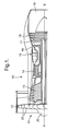
- Fig. 3 is a sectional view along the line A-A of Fig. 2; and
- Fig. 4 is a sectional view along the line B-B of Fig. 2.
- Referring to Fig. 1, a gas turbine engine is generally indicated at 10 and comprises, in axial flow series, an
air intake 11, apropulsive fan 12, anintermediate pressure compressor 13, ahigh pressure compressor 14,combustion equipment 15, ahigh pressure turbine 16, anintermediate pressure turbine 17, alow pressure turbine 18 and anexhaust nozzle 19. - The
gas turbine engine 10 works in a conventional manner so that air entering theintake 11 is accelerated by thefan 12 which produces two air flows: a first air flow into theintermediate pressure compressor 13 and a second air flow which provides propulsive thrust. Theintermediate pressure compressor 13 compresses the air flow directed into it before delivering that air to thehigh pressure compressor 14 where further compression takes place. - The compressed air exhausted from the
high pressure compressor 14 is directed into thecombustion equipment 15 where it is mixed with fuel and the mixture combusted. The resultant hot combustion products then expand through, and thereby drive, the high, intermediate andlow pressure turbines nozzle 19 to provide additional propulsive thrust. The high, intermediate andlow pressure turbines intermediate pressure compressors fan 12 by suitable interconnecting shafts. - The
propulsive fan 12 comprises afan rotor 20 carrying a plurality of equi-angularly spaced radially outwardly extendingfan blades 22. In more detail, and referring to Figs. 2 to 4, eachblade 22 comprises aroot portion 24, a radially extendingaerofoil portion 26 and atransition portion 28 between theroot portion 24 and theaerofoil portion 26. Theaerofoil portion 26 and thetransition portion 28 are defined by a first, generally concave,wall member 30 and a second, generally convex,wall member 32. Theroot portion 24 comprises a dovetail root, a firtree root, or other suitably shaped root for fitting in a correspondingly shaped slot in thefan rotor 20. - As indicated above, each
fan blade 22 is designed to progressively break up under a buckling action in the event of detachment from thefan rotor 20. Due to the fact that fan blades conventionally increase in strength from the tip of theaerofoil portion 26 towards theroot portion 24, there comes a point when thefan blade 20 no longer buckles and the remaining portion of thefan blade 20, which includes theroot portion 24 and thetransition portion 28, impacts the fan containment region of the fan casing. - In embodiments of the invention, as best seen in Fig. 4, the
outer surface convex wall members blade 22. The thickness of thetransition portion 28 is thus reduced relative to existing blades and consequently has a much lower mass and stiffness, thereby reducing the impact forces when a remaining portion of a detached fan blade impacts the fan containment region of a fan casing. - In the embodiment shown in Fig. 4, the distance between the
outer surfaces convex wall members transition portion 28 than in theaerofoil portion 26. This may not, however, be the case with allblades 22. - To form the
aerofoil portion 26, the peripheral edges of substantially planar panels are secured together by diffusion bonding and these are then superplastically deformed to provide the concave andconvex wall members cavity 34 between the concave andconvex wall members cavity 34 and, as a result, theblade 22 has a relatively low mass and a very high bending stiffness in theaerofoil portion 26. - Referring to Fig. 4, the
cavity 34 terminates at the radially inner end of theaerofoil portion 26 and does not extend significantly into thetransition portion 28 where the concave andconvex wall members blade 22. - In order to provide one or both of the concave and
convex wall members blade 22 and thereby provide the reduction in mass and stiffness in thetransition portion 28, -material is removed from the concave andconvex wall members transition portion 28 by a suitable machining process. The mass and bending stiffness of theblade 22 is thus significantly lower in thetransition portion 28 than in the transition portion of existing blades. - Embodiments of the invention therefore provide the advantage that when the remaining portion, including the
transition portion 28, of adetached blade 22 impacts the fan containment region of the fan casing, thetransition portion 28 more readily flexes and deforms, thereby dissipating energy and reducing the impact forces. This deformation increases the impact surface area between thetransition portion 28 and the fan containment region of the fan casing thereby facilitating said dissipation of energy and reduction of the impact forces. The mass of theblade 22 in thetransition portion 28 is also significantly reduced relative to existing blades, and this further reduces the impact forces with the fan containment region of the fan casing in the event of blade detachment. - As can be seen in Fig. 4, the concave and
convex wall members outer surfaces concave recess transition portion 28, each of therecesses blade 22 between theroot portion 24 and theaerofoil portion 26. - In embodiments of the invention, the
recesses cellular material 40 which may be in the form of a metal foam, for example a nickel foam, a nickel alloy foam, a titanium foam, a titanium alloy foam, an aluminium foam, an aluminium alloy foam a magnesium alloy foam or a steel foam. - The
cellular material 40 provides theblade 22 with a desired aerodynamic profile above an annulus line, in which theblade 22 is in the gas flow path, and with a suitable surface, below the annulus line, for annulus filler seals to bear against. - The
cellular material 40 advantageously also provides for further dissipation of energy and reduction of the impact forces upon impact of a detached blade with the blade containment region of the fan casing. Thecellular material 40 effectively cushions the impact between thetransition portion 28 and the fan containment region and readily deforms to provide said further dissipation of energy and reduction of the impact forces. - If desired, a
membrane cellular material 40 and, as can be seen in Fig. 4, this is substantially coplanar with theouter surfaces convex wall members aerofoil portion 26 and merges with the adjacentouter surfaces membrane blade 22 under some circumstances and/or improve sealing with the annulus filler seals. - As will be understood by those skilled in the art, by providing improved dissipation of energy upon impact with the fan containment region and by providing a reduction in the impact forces, the use of the
blade 22 reduces the need to provide additional material to the fan containment region to contain detached fan blades. - Although embodiments of the invention have been described in the preceding paragraphs with reference to various examples, it should be appreciated that various modifications to the examples given may be made without departing from the scope of the present invention, as claimed.
- For example, the
cellular material 40 may be omitted from therecesses recesses cellular material 40. One or both of themembranes - The
cellular material 40 may be any suitable material and is not limited to a metal foam. The cellular material may have a honeycomb structure. - The
cavity 34 may extend partially into thetransition portion 28.
Claims (10)
Applications Claiming Priority (1)
| Application Number | Priority Date | Filing Date | Title |
|---|---|---|---|
| GBGB0613441.5A GB0613441D0 (en) | 2006-07-06 | 2006-07-06 | Blades |
Publications (2)
| Publication Number | Publication Date |
|---|---|
| EP1876324A2 true EP1876324A2 (en) | 2008-01-09 |
| EP1876324A3 EP1876324A3 (en) | 2012-05-23 |
Family
ID=36926570
Family Applications (1)
| Application Number | Title | Priority Date | Filing Date |
|---|---|---|---|
| EP07252342A Withdrawn EP1876324A3 (en) | 2006-07-06 | 2007-06-09 | Gas turbine blade |
Country Status (3)
| Country | Link |
|---|---|
| US (1) | US7946827B2 (en) |
| EP (1) | EP1876324A3 (en) |
| GB (1) | GB0613441D0 (en) |
Cited By (1)
| Publication number | Priority date | Publication date | Assignee | Title |
|---|---|---|---|---|
| EP2182168A1 (en) * | 2008-10-28 | 2010-05-05 | General Electric Company | Fabricated hybrid turbine blade |
Families Citing this family (10)
| Publication number | Priority date | Publication date | Assignee | Title |
|---|---|---|---|---|
| DE1468438A1 (en) * | 1963-01-22 | 1968-12-19 | Onoda Cement Co Ltd | Process for the production of fluorine derivatives of halogenated hydrocarbons |
| US10731511B2 (en) * | 2012-10-01 | 2020-08-04 | Raytheon Technologies Corporation | Reduced fan containment threat through liner and blade design |
| US9650914B2 (en) * | 2014-02-28 | 2017-05-16 | Pratt & Whitney Canada Corp. | Turbine blade for a gas turbine engine |
| US9789536B2 (en) | 2015-01-20 | 2017-10-17 | United Technologies Corporation | Dual investment technique for solid mold casting of reticulated metal foams |
| US9737930B2 (en) | 2015-01-20 | 2017-08-22 | United Technologies Corporation | Dual investment shelled solid mold casting of reticulated metal foams |
| US9789534B2 (en) | 2015-01-20 | 2017-10-17 | United Technologies Corporation | Investment technique for solid mold casting of reticulated metal foams |
| US9884363B2 (en) | 2015-06-30 | 2018-02-06 | United Technologies Corporation | Variable diameter investment casting mold for casting of reticulated metal foams |
| US9731342B2 (en) | 2015-07-07 | 2017-08-15 | United Technologies Corporation | Chill plate for equiax casting solidification control for solid mold casting of reticulated metal foams |
| BE1023290B1 (en) * | 2015-07-22 | 2017-01-24 | Safran Aero Boosters S.A. | AUBE COMPOSITE COMPRESSOR OF AXIAL TURBOMACHINE |
| US11111815B2 (en) * | 2018-10-16 | 2021-09-07 | General Electric Company | Frangible gas turbine engine airfoil with fusion cavities |
Citations (1)
| Publication number | Priority date | Publication date | Assignee | Title |
|---|---|---|---|---|
| US5490764A (en) | 1994-05-23 | 1996-02-13 | General Electric Company | Unshrouded blading for high bypass turbofan engines |
Family Cites Families (4)
| Publication number | Priority date | Publication date | Assignee | Title |
|---|---|---|---|---|
| DE2658876C3 (en) | 1976-12-24 | 1983-11-10 | Hütter, Ulrich, Prof. Dr.-Ing., 7312 Kirchheim | Shell bodies, for example hydrofoils or rotor blades, in composite construction |
| US5931641A (en) | 1997-04-25 | 1999-08-03 | General Electric Company | Steam turbine blade having areas of different densities |
| EP1128023A1 (en) | 2000-02-25 | 2001-08-29 | Siemens Aktiengesellschaft | Turbine rotor blade |
| US7189064B2 (en) * | 2004-05-14 | 2007-03-13 | General Electric Company | Friction stir welded hollow airfoils and method therefor |
-
2006
- 2006-07-06 GB GBGB0613441.5A patent/GB0613441D0/en not_active Ceased
-
2007
- 2007-06-09 EP EP07252342A patent/EP1876324A3/en not_active Withdrawn
- 2007-06-11 US US11/808,546 patent/US7946827B2/en not_active Expired - Fee Related
Patent Citations (1)
| Publication number | Priority date | Publication date | Assignee | Title |
|---|---|---|---|---|
| US5490764A (en) | 1994-05-23 | 1996-02-13 | General Electric Company | Unshrouded blading for high bypass turbofan engines |
Cited By (3)
| Publication number | Priority date | Publication date | Assignee | Title |
|---|---|---|---|---|
| EP2182168A1 (en) * | 2008-10-28 | 2010-05-05 | General Electric Company | Fabricated hybrid turbine blade |
| JP2010106833A (en) * | 2008-10-28 | 2010-05-13 | General Electric Co <Ge> | Hybrid turbine blade |
| CN101725372A (en) * | 2008-10-28 | 2010-06-09 | 通用电气公司 | Fabricated hybrid turbine blade |
Also Published As
| Publication number | Publication date |
|---|---|
| GB0613441D0 (en) | 2006-08-16 |
| US7946827B2 (en) | 2011-05-24 |
| US20080101960A1 (en) | 2008-05-01 |
| EP1876324A3 (en) | 2012-05-23 |
Similar Documents
| Publication | Publication Date | Title |
|---|---|---|
| US7946827B2 (en) | Blades | |
| EP2589461B1 (en) | Rotor blade with bonded cover | |
| EP2348192B1 (en) | Fan airfoil sheath | |
| EP2405101B1 (en) | A composite turbomachine blade | |
| EP2281746B1 (en) | Titanium sheath and airfoil assembly | |
| EP2096269B1 (en) | Fan track liner assembly for a gas turbine engine | |
| EP2932044B1 (en) | Hollow airfoil with composite cover and foam filler | |
| EP2149680B1 (en) | Gas turbine engine | |
| US8075274B2 (en) | Reinforced composite fan blade | |
| US20060182633A1 (en) | Turbine blade | |
| US11286782B2 (en) | Multi-material leading edge protector | |
| EP3364042B1 (en) | Fan for gas turbine engine with mistuned blades | |
| EP2336500A2 (en) | Aircraft engine inlet having zone of deformation | |
| EP3034786B1 (en) | A gas turbine fan blade having a plurality of shear zones | |
| US7118346B2 (en) | Compressor blade | |
| US20140030107A1 (en) | Decoupled compressor blade of a gas turbine | |
| CN110966255B (en) | Metallic compliant tip fan blade | |
| EP2993299A1 (en) | Composite fan blade and corresponding manufacturing method | |
| US9482102B2 (en) | Method of reinforcing a mechanical part | |
| EP2636846A1 (en) | Fabricated turbine airfoil | |
| US7090463B2 (en) | Guide vane | |
| US20080019838A1 (en) | Blades | |
| US11156125B2 (en) | Containment assembly | |
| EP3372786B1 (en) | High-pressure compressor rotor blade with leading edge having indent segment | |
| US11879354B2 (en) | Rotor blade with frangible spar for a gas turbine engine |
Legal Events
| Date | Code | Title | Description |
|---|---|---|---|
| PUAI | Public reference made under article 153(3) epc to a published international application that has entered the european phase |
Free format text: ORIGINAL CODE: 0009012 |
|
| AK | Designated contracting states |
Kind code of ref document: A2 Designated state(s): AT BE BG CH CY CZ DE DK EE ES FI FR GB GR HU IE IS IT LI LT LU LV MC MT NL PL PT RO SE SI SK TR |
|
| AX | Request for extension of the european patent |
Extension state: AL BA HR MK YU |
|
| PUAL | Search report despatched |
Free format text: ORIGINAL CODE: 0009013 |
|
| AK | Designated contracting states |
Kind code of ref document: A3 Designated state(s): AT BE BG CH CY CZ DE DK EE ES FI FR GB GR HU IE IS IT LI LT LU LV MC MT NL PL PT RO SE SI SK TR |
|
| AX | Request for extension of the european patent |
Extension state: AL BA HR MK RS |
|
| RIC1 | Information provided on ipc code assigned before grant |
Ipc: F01D 21/04 20060101ALI20120418BHEP Ipc: F01D 5/28 20060101ALI20120418BHEP Ipc: F01D 5/14 20060101AFI20120418BHEP |
|
| 17P | Request for examination filed |
Effective date: 20121107 |
|
| AKX | Designation fees paid |
Designated state(s): AT BE BG CH CY CZ DE DK EE ES FI FR GB GR HU IE IS IT LI LT LU LV MC MT NL PL PT RO SE SI SK TR |
|
| RAP1 | Party data changed (applicant data changed or rights of an application transferred) |
Owner name: ROLLS-ROYCE PLC |
|
| STAA | Information on the status of an ep patent application or granted ep patent |
Free format text: STATUS: THE APPLICATION HAS BEEN WITHDRAWN |
|
| 18W | Application withdrawn |
Effective date: 20151120 |