EP1871215B1 - Endoscopic apparatus having an elevator - Google Patents
Endoscopic apparatus having an elevator Download PDFInfo
- Publication number
- EP1871215B1 EP1871215B1 EP06750220A EP06750220A EP1871215B1 EP 1871215 B1 EP1871215 B1 EP 1871215B1 EP 06750220 A EP06750220 A EP 06750220A EP 06750220 A EP06750220 A EP 06750220A EP 1871215 B1 EP1871215 B1 EP 1871215B1
- Authority
- EP
- European Patent Office
- Prior art keywords
- elevator
- grasping
- medical device
- tip
- endoscope
- Prior art date
- Legal status (The legal status is an assumption and is not a legal conclusion. Google has not performed a legal analysis and makes no representation as to the accuracy of the status listed.)
- Active
Links
Images

Classifications
-
- A—HUMAN NECESSITIES
- A61—MEDICAL OR VETERINARY SCIENCE; HYGIENE
- A61B—DIAGNOSIS; SURGERY; IDENTIFICATION
- A61B1/00—Instruments for performing medical examinations of the interior of cavities or tubes of the body by visual or photographical inspection, e.g. endoscopes; Illuminating arrangements therefor
- A61B1/005—Flexible endoscopes
- A61B1/01—Guiding arrangements therefore
-
- A—HUMAN NECESSITIES
- A61—MEDICAL OR VETERINARY SCIENCE; HYGIENE
- A61B—DIAGNOSIS; SURGERY; IDENTIFICATION
- A61B1/00—Instruments for performing medical examinations of the interior of cavities or tubes of the body by visual or photographical inspection, e.g. endoscopes; Illuminating arrangements therefor
- A61B1/00064—Constructional details of the endoscope body
- A61B1/00071—Insertion part of the endoscope body
- A61B1/0008—Insertion part of the endoscope body characterised by distal tip features
- A61B1/00087—Tools
-
- A—HUMAN NECESSITIES
- A61—MEDICAL OR VETERINARY SCIENCE; HYGIENE
- A61B—DIAGNOSIS; SURGERY; IDENTIFICATION
- A61B1/00—Instruments for performing medical examinations of the interior of cavities or tubes of the body by visual or photographical inspection, e.g. endoscopes; Illuminating arrangements therefor
- A61B1/00064—Constructional details of the endoscope body
- A61B1/00071—Insertion part of the endoscope body
- A61B1/0008—Insertion part of the endoscope body characterised by distal tip features
- A61B1/00098—Deflecting means for inserted tools
-
- A—HUMAN NECESSITIES
- A61—MEDICAL OR VETERINARY SCIENCE; HYGIENE
- A61B—DIAGNOSIS; SURGERY; IDENTIFICATION
- A61B1/00—Instruments for performing medical examinations of the interior of cavities or tubes of the body by visual or photographical inspection, e.g. endoscopes; Illuminating arrangements therefor
- A61B1/012—Instruments for performing medical examinations of the interior of cavities or tubes of the body by visual or photographical inspection, e.g. endoscopes; Illuminating arrangements therefor characterised by internal passages or accessories therefor
- A61B1/018—Instruments for performing medical examinations of the interior of cavities or tubes of the body by visual or photographical inspection, e.g. endoscopes; Illuminating arrangements therefor characterised by internal passages or accessories therefor for receiving instruments
-
- A—HUMAN NECESSITIES
- A61—MEDICAL OR VETERINARY SCIENCE; HYGIENE
- A61B—DIAGNOSIS; SURGERY; IDENTIFICATION
- A61B17/00—Surgical instruments, devices or methods, e.g. tourniquets
- A61B17/28—Surgical forceps
- A61B17/29—Forceps for use in minimally invasive surgery
-
- A—HUMAN NECESSITIES
- A61—MEDICAL OR VETERINARY SCIENCE; HYGIENE
- A61B—DIAGNOSIS; SURGERY; IDENTIFICATION
- A61B17/00—Surgical instruments, devices or methods, e.g. tourniquets
- A61B17/00234—Surgical instruments, devices or methods, e.g. tourniquets for minimally invasive surgery
- A61B2017/00292—Surgical instruments, devices or methods, e.g. tourniquets for minimally invasive surgery mounted on or guided by flexible, e.g. catheter-like, means
- A61B2017/00296—Surgical instruments, devices or methods, e.g. tourniquets for minimally invasive surgery mounted on or guided by flexible, e.g. catheter-like, means mounted on an endoscope
-
- A—HUMAN NECESSITIES
- A61—MEDICAL OR VETERINARY SCIENCE; HYGIENE
- A61B—DIAGNOSIS; SURGERY; IDENTIFICATION
- A61B17/00—Surgical instruments, devices or methods, e.g. tourniquets
- A61B17/00234—Surgical instruments, devices or methods, e.g. tourniquets for minimally invasive surgery
- A61B2017/00292—Surgical instruments, devices or methods, e.g. tourniquets for minimally invasive surgery mounted on or guided by flexible, e.g. catheter-like, means
- A61B2017/003—Steerable
Definitions
- the present invention relates to medical devices, and more particularly, to endoscopes having a medical instrument elevator.
- Endoscopic devices have been commonly used for various procedures, typically in the abdominal area. Endoscopy is the examination and inspection of the interior of body organs, joints or cavities through an endoscope. Endoscopy allows physicians to peer through the body's passageways. An endoscopic procedure may be used to diagnose various conditions by close examination of internal organ and body structures and may also guide therapy and repair, such as the removal of torn cartilage from the bearing surfaces of a joint. A biopsy, a procedure involving tissue sampling for pathologic testing, may also be performed under endoscopic guidance.
- endoscopic procedures include the following known procedures: gastroscopy, sigmoidoscopy and colonoscopy, esophago gastro duodenoscopy (EGD), endoscopic retrograde cholangiopancreatography (ERCP), and bronchoscopy.
- endoscopes having an elevator used to orient the wire guide and to lock the distal end of the wire guide.
- the elevator includes a v-shaped groove.
- the v-shaped groove is typically used to guide the wire guide to a central position relative to the endoscope.
- the elevator having a v-shaped groove is further used to lock the distal end of the guide wire.
- US 2002/091303 discloses a wire engagement groove in an elevator base, the groove having engagement protrusions.
- Endoscopes using a rigid elevator lock and/or a v-shaped groove arrangement may be improved.
- the elevator may tear, scrape, or otherwise affect wire guides or other instruments used therewith. This is particular with soft, TeflonTM-coated wire guides.
- TeflonTM-coated wire guides When such wire guides are positioned within the v-shaped groove of the elevator, even slight axial movement of the wire guide may result in a torn, scraped, stripped or damaged wire guide. Such result to a wire guide may undesirably require replacing the wire guide during the procedure. This, in turn, undesirably lengthens the overall procedure time and may be costly.
- the elevator may compress elongate devices such as catheters, thereby preventing the passage of fluids therethrough or impeding the operation of the catheter device.
- inventions of the present invention as defined by the independent claims provide an endoscopic elevator system and an endoscopis assembly having enhanced features for grasping of a medical device, e.g., a catheter or wire guide.
- a medical device e.g., a catheter or wire guide.
- the present invention solves some of the current challenges in the endoscope industry. That is, embodiments of the present invention provide a way, during an endoscopic procedure, to maintain a relatively firm grasp of the medical device while reducing (or at least without compromising) the risk of scraping, tearing, stripping or other damage to the medical device.
- Figure 1 a is a perspective view of an endoscopic system comprising an endoscope in accordance with one embodiment of the present invention
- Figure 1b is a perspective view of the endoscope depicted in Figure 1A ;
- Figure 1c is an elevated view of a distal tip of the endoscope in accordance with one embodiment of the present invention.
- Figure 2 is an enlarged view of the distal tip of the endoscope in accordance with one embodiment of the present invention
- Figure 3 is a cross-sectional view of the distal tip of the endoscope insertion portion of the endoscope taken along line 3-3;
- FIG. 4 is a side view of an elevator in accordance with one embodiment of the present invention.
- Figure 5 is a cross-sectional view of the tip of the endoscope of Figure 1 , depicting a wire guide secured by an elevator;
- Figure 6 is an elevated view of an elevator according to one embodiment of the present invention.
- Figure 7 is a side view of the elevator in Figure 6 having engaging ribs according to one embodiment of the present invention.
- FIGS 8a-8c are enlarged side views of the elevator in circle 8 of Figure 7 in accordance with examples of the present invention.
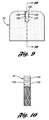
- Figure 9 is an elevated view of an elevator in accordance with one embodiment of the present invention.
- Figure 10 is a cross-sectional view of the elevator in Figure 9 taken along line 10-10 in accordance with one embodiment of the present invention.
- FIGS 11a-11c are elevated views of elevators in accordance with other embodiments of the present invention.
- the present invention generally provides an endoscopic elevator and an endoscopic assembly having enhanced features of grasping and reduced scraping of a medical device.
- Embodiments of the present invention allows a practitioner to relatively firmly grasp the medical device within an endoscope, while reducing the risk of scraping, tearing, or stripping or other damage to the medical device (e.g., catheter, wire guide.
- an endoscopic elevator comprises a grasping tip having a body with ridges formed thereon. The ridges are preferably made of polymeric or elastomeric material to engage and receive the medical device, lessening the risk of undesirably scraping thereof.
- Figures 1-3 illustrate an endoscopic system comprising an endoscope having an elevator with a distal tip. Additional details relating to the endoscopic system are described in U.S. Patent No. 6,827,683 , entitled “ENDOSCOPE SYSTEM AND MEDICAL TREATMENT METHOD” issued December 7, 2004 to Takashi Otawara, to which reference is directed in its entirety.
- Figure 1a illustrates an endoscopic system 10 comprising an endoscope 11 in accordance with one embodiment of the present Invention.
- the endoscope 11 comprises an insertion tube 12 to be inserted into a body cavity for various endoscopic procedures including gastroscopy, sigmoidoscopy and colonoscopy, esophago gastro duodenoscopy (EGD), endoscopic retrograde cholanglopancreatography (ERCP), and bronchoscopy.
- the endoscope 11 comprises an insertion tube 12 having a plurality of channel ports 13 through which endoscopic units may be disposed.
- endoscopic units disposed in one of the ports may include one embodiment of an improved elevator having a tip.
- the endoscope 11 further include a control system 14 that is in mechanical and fluid communication with the insertion tube 12.
- the control system 14 is configured to control the Insertion tube 12 and endoscopic parts disposed therein.
- the control system 14 includes first and second control knobs 16, 18.
- the control knobs 16, 18 are configured to be in mechanical communication with the insertion tube 12.
- the control knobs 16, 18 allow the physician to control and guide, by known means, the insertion tube 12 through vessels and cavities of a patient.
- the control system 14 further includes valve switches (e.g., suction valve 20, air/water valve 21, camera valve 22), each of which are in communication to one of the channel ports 13 of the insertion tube 12.
- the suction valve switch 20 when activated, allows a vacuum from a suction source through a suction channel port for suctioning unwanted plaque and debris from the patient.
- the distal end of the insertion tube 12 is inserted, rectally or orally, to a predetermined endoscopic location within a patient. Insertion of the insertion tube 12 may be rectally or orally depending on the endoscopic procedure.
- the endoscope in combination with the elevator having the tip reduce the risk of damage, e.g., tearing or scraping, of the wire guide.
- the insertion tube 12 comprises an operating portion 25 connected to the control system 14 and extending to an insertion portion protecting member 26.
- a control system 20 is connected to the operating portion 25 and is configured to control the insertion tube 12.
- the insertion tube 12 is composed of components that include a flexible tube 28, a flexure 29 connected to the flexible tube 28, and an endoscope tip 30 connect to the flexure 29.
- a universal cord 31, on one end, is connected and in communication with the control system 20. On the other end, the cord 31 has a connector 18 attached thereto.
- the connector 18 is in communication to a light guide tube and electrical contact, and is connected to a light source apparatus 32 and an image processing apparatus 33 (external devices). These external devices may include a monitor 34, an input keyboard 35, a suction pump apparatus 36, and an irrigation bottle 37, and other suitable apparatus are installed on a rack 39 equipped with carriers 38.
- a concave, depressed cutout 40 is formed on the outer circumferential surface of the tip 30.
- a channel opening 42 is formed on one side of the cutout 40, and an objective lens 44 and a light source 46 are disposed on another side of the cutout 40 for imaging. Both the objective lens 44 and the light source 46 are positioned adjacent to the channel opening 42.
- the tip 30 further comprises a nozzle 48 extending from a back wall surface 50 of the cutout 40. The nozzle 48 allows a stream of water, air, or the like to spray towards the outer surface of the objective lens 44 to clean the lens surface.
- tip 30 further includes a guide catheter 52 and a wire guide 56 disposed through the guide catheter 52.
- the tip 30 further includes an elevator 43 configured to receive the guide catheter and/or wire guide for elevating the guide catheter 52 or wire guide 56.
- the elevator 43 includes a distal tip 112 disposed thereon.
- the distal tip 112 comprises aids to reduce the risk of damage, e.g., tearing or scraping, the wire guide.
- the distal tip 112 comprises a body 113 having lateral ridges or ribs 114 to aid in reducing the risk of damage to the wire guide.
- the elevator 43 is formed from an elastomeric material to prevent stripping of instruments used with the endoscope.
- the elastomeric elevator allows a clinician to more firmly grasp and secure the distal end of an instrument or wire guide relative to the endoscope as compared to endoscopes having rigid elevators.
- the elastomeric elevator can be formed from rubber.
- cuff can be provided with an elastomeric outer surface.
- Figures 2 and 3 illustrate that the endoscope tip 30 includes a cuff 60 as the main body of the tip 30, and a sleeve or cover 62 that covers the perimeter of the cuff 60.
- the cover 62 is formed using a nonconductive member such as any suitable polymeric material, e.g., high density polyethylene or polypropylene.
- the cover 62 is attached to the cuff 60 by any suitable means, e.g., by adhesive bonding.
- the cuff 60 is in fluid communication with the working channel 63, which acts as a passageway for the insertion of the device, e.g., wire guide or catheter.
- a passageway 64 is formed therethrough having an accommodation space 65 formed adjacent the cuff 60 and the tip cover 62.
- a channel 67 is formed through the tip 30 such that the tip opening of the treatment instrument is able to be disposed through the channel 63 defining an opening in the accommodation space 65.
- the accommodation space 65 houses an elevator 43.
- the elevator 43 is used to orient medical instruments such as a catheter (depicted in Figure 2 ), or forceps, extending distally within the working channel 63.
- the elevator 43 preferably is also used to secure the distal end of the medical instrument or wire guide relative to the endoscope.
- a guide plane 69 for guiding a treatment instrument is formed from a groove with any desired shape formed In the treatment instrument elevator 43 to provide a connection with the insertion guide passage 64.
- the elevator turning support 68 is located off-center relative to the tip opening of the passageway 64.
- the elevator 43 is mounted such that the distal portion of the elevator pivots or rotates across within the accommodation space 65.
- Figure 4 illustrates the elevator 43 having a transverse passageways 102 and 103 formed therethrough, each having optional metal sleeves 104 and 105, respectively, disposed thereon.
- the metal sleeves are configured to provide transverse rigidity to the elevator.
- the proximal end of the elevator 43 is attached so as to pivot around the elevator turning support 68 provided to the cuff 60.
- Figure 3 further illustrates an elevator wire 90 connected to the elevator 43.
- the elevator wire 90 is located at the operating portion 25 and extends through a guide tube 92 and a guide pipe 91 connected to the guide tube 92.
- the elevator wire 90 is in mechanical communication with the control system 14 so that manipulations at the control system 14 result in movement of the elevator wire 90 relative to the endoscope.
- Figure 3 depicts (in phantom) movement of the elevator 43 when the elevator wire 90 is actuated at the control system 14, moving the position of the elevator 43 about the elevator turning support 68 as the elevator wire 90 is retracted or pulled.
- the elevator 43 is rotated about the elevator turning support 68 by manipulating or actuating the control system 14 to pull or retract the elevator wire 90.
- the result moves the wire guide 56 in the direction of the arrow P and pushes the elevator 43 against the cuff 60.
- the wire guide 56 is formed from a relatively axially stiff material, it tends to remain straight when pushed against the cuff 60, creating a reactive force in the direction of the arrow Fr in Figure 5 .
- the wire guide 56 is pressed against the wire guide catch groove 59 depicted in Figure 3 .
- the wire guide is secured.
- FIG. 6 illustrates the elevator 43 comprising a tip 112 disposed on the elevator 43 in accordance with one embodiment of the present invention.
- the tip 112 is disposed over the elevator 43 and adhered thereon by any suitable means, e.g., sonic bonding, thermal bonding, or adhesive bonding.
- the tip 112 comprises a body 113 having a plurality of lateral ridges or ribs 114 formed thereon.
- the body 113 has an opening formed and is disposed over the elevator 43 with the lateral ridges 114 positioned thereacross to receive and contact the device.
- the lateral ridges 114 are configured to contact and engage the device, e.g., wire guide or catheter, within the endoscope during usage thereof.
- the lateral ridges 114 aid in retaining and guiding the wire guide 56, while also reducing the risk of damage to the wire guide. This is accomplished due to the lateral structure of the ridges 113 and the composition thereof.
- the ridges 114 may take on any desirable or suitable formation to contact the device (e.g. wire guide).
- the tip 112 allows a physician to more firmly grasp and secure the distal end of an instrument or wire guide relative to the endoscope as compared to endoscopes having bare, rigid elevators.
- cuff 60 can be provided with an elastomeric outer surface 66.
- the lateral ridges 114 may be made of any suitable material including elastomeric and polymeric materials, e.g., polytetrafluoroethylene (PTFE), polyethylene, polypropylene, perfluoroelastomer, fluoroelastomer, nitrile, neoprene, polyurethane, silicone, polytetrafluroethylene, styrene-butadiene, rubber, or polyisobutylene.
- the tip 112 may be made of any suitable material that will cooperate with the device to absorb and deform when in contact therewith, thereby reducing the risk of damage to the wire guide.
- Figures 8a-8c further illustrate various configurations of ridges or ribs 114, 120, 124, respectively, formed on the elevator.
- the ridges 114 may take on any desirable or suitable shape for contact with the wire guide.
- the ridges 114, 120, 124 may have a cross-sectional shape that is semi-circular or arcuate ( Figure 8a ), triangular ( Figure 8b ), or rectangular ( Figure 8c ).
- Figure 9 illustrates the elevator 43 comprising a grasping slot 130 in accordance with one embodiment of the present invention.
- the grasping slot may take on any suitable shaped or form for grasping of a medical device.
- the grasping slot 130 is narrowly formed by inner sides 132 that define the grasping slot 130 through the elevator 43.
- the grasping slot 130 is centrally formed through the elevator 43 for receiving a medical device (e.g., catheter or wire guide) and grasping the device during operation of the endoscope.
- a medical device e.g., catheter or wire guide
- FIGS 9 and 10 illustrate the elevator having inner sides 132 in accordance with one embodiment of the present invention.
- inner sides 132 include side grasping members 134 formed thereon.
- side grasping members 134 are ridges or ribs that are oppositely formed laterally across each of the inner sides.
- the side grasping members may be formed on either or both of the inner sides, in any suitable shape, and in staggered configuration.
- the inner grasping members may be formed longitudinally or in different patterns without falling beyond the scope or spirit of the present invention.
- control system of the endoscope may be manipulated to actuate the elevator, moving the elevator to engage the medical device, e.g., catheter or wire guide.
- the medical device e.g., catheter or wire guide.
- the medical device is worked through the grasping slot 130 of the elevator 43, thereby engaging the medical device with the inner sides 132 of the elevator 43.
- the side grasping members 134 engage the device and, due to the polymeric material of the elevator 43, partially deform and absorb the device to reduce the risk of scraping thereof.
- the side grasping members 134 receive the medical device when disposed within the slot for enhanced grasping and reduced risk of scraping of the medical device.
- cuff 60 can be provided with an elastomeric outer surface 66.
- Figures 11a-11c further illustrate various configurations of grasping slots 140, 150, 160 formed through the elevator.
- the grasping slots may take on any desirable or suitable shape for grasping of a medical device of an endoscope.
- the grasping slot 140 of elevator 141 may have a cross-sectional shape that is semi-circular or arcuate.
- the grasping slot 140 has an arcuate side 142 that defines the grasping slot 140.
- the arcuate side 142 includes grasping members 144 formed thereon for grasping the medical device.
- Figure 11b illustrates grasping slot 150 of elevator 151 in accordance with another embodiment of the present invention.
- the grasping slot 150 has inner and arcuate sides 152 that define the slot 150.
- the sides 152 include grasping member 154 formed thereon for grasping the medical device.
- Figure 11c illustrates grasping slot 160 of elevator 161 in accordance with yet another embodiment of the present invention.
- the grasping slot 160 has tapered and arcuate sides 162 that define the slot 160.
- the sides 162 include grasping members 164 formed thereon for grasping the medical device.
Landscapes
- Health & Medical Sciences (AREA)
- Life Sciences & Earth Sciences (AREA)
- Surgery (AREA)
- Biomedical Technology (AREA)
- Medical Informatics (AREA)
- Optics & Photonics (AREA)
- Pathology (AREA)
- Radiology & Medical Imaging (AREA)
- Biophysics (AREA)
- Engineering & Computer Science (AREA)
- Physics & Mathematics (AREA)
- Heart & Thoracic Surgery (AREA)
- Nuclear Medicine, Radiotherapy & Molecular Imaging (AREA)
- Molecular Biology (AREA)
- Animal Behavior & Ethology (AREA)
- General Health & Medical Sciences (AREA)
- Public Health (AREA)
- Veterinary Medicine (AREA)
- Endoscopes (AREA)
- De-Stacking Of Articles (AREA)
Abstract
Description
- This application claims the benefit of
U.S. Provisional Application no. 60/671,951, filed on April 15, 2005 - This application also claims the benefit of
U.S. Provisional Application no. 60/779,181, filed on March 3, 2006 - This application also claims the benefit of
U.S. Provisional Application no. 60/779,182, filed on March 3, 2006 - The present invention relates to medical devices, and more particularly, to endoscopes having a medical instrument elevator.
- Endoscopic devices have been commonly used for various procedures, typically in the abdominal area. Endoscopy is the examination and inspection of the interior of body organs, joints or cavities through an endoscope. Endoscopy allows physicians to peer through the body's passageways. An endoscopic procedure may be used to diagnose various conditions by close examination of internal organ and body structures and may also guide therapy and repair, such as the removal of torn cartilage from the bearing surfaces of a joint. A biopsy, a procedure involving tissue sampling for pathologic testing, may also be performed under endoscopic guidance. For example, endoscopic procedures include the following known procedures: gastroscopy, sigmoidoscopy and colonoscopy, esophago gastro duodenoscopy (EGD), endoscopic retrograde cholangiopancreatography (ERCP), and bronchoscopy.
- Many current endoscopic systems include endoscopes having an elevator used to orient the wire guide and to lock the distal end of the wire guide. In many such endoscopes, the elevator includes a v-shaped groove. The v-shaped groove is typically used to guide the wire guide to a central position relative to the endoscope. The elevator having a v-shaped groove is further used to lock the distal end of the guide wire. Reference is here directed to
US 2002/091303 which discloses a wire engagement groove in an elevator base, the groove having engagement protrusions. Reference is also directed toUS 4407273 . - Endoscopes using a rigid elevator lock and/or a v-shaped groove arrangement, however, may be improved. For example, in many situations, the elevator may tear, scrape, or otherwise affect wire guides or other instruments used therewith. This is particular with soft, Teflon™-coated wire guides. When such wire guides are positioned within the v-shaped groove of the elevator, even slight axial movement of the wire guide may result in a torn, scraped, stripped or damaged wire guide. Such result to a wire guide may undesirably require replacing the wire guide during the procedure. This, in turn, undesirably lengthens the overall procedure time and may be costly.
- Many other endoscopes are provided with rigid, flat-edged elevators. One challenge is that wire guide orientation is difficult to control with flat-edged elevators. Specifically, the wire guide tends to move from side to side relative to the elevator, thereby challenging the physician to insert the wire guide into a target anatomy. Moreover, when flat-edged elevators are used to lock the distal end of an instrument, tearing, scraping, stripping or other undesirable damaged effect on the instrument can also result.
- Another issue is that during use the elevator may compress elongate devices such as catheters, thereby preventing the passage of fluids therethrough or impeding the operation of the catheter device.
- Thus, there is a need for an elevator design that reduces the risk of tearing, scraping, stripping or other damaging of devices (e.g., wire guides or catheter) during deployment in a body vessel and allows flow of fluid therethrough during use.
- The embodiments of the present invention as defined by the independent claims provide an endoscopic elevator system and an endoscopis assembly having enhanced features for grasping of a medical device, e.g., a catheter or wire guide. The present invention solves some of the current challenges in the endoscope industry. That is, embodiments of the present invention provide a way, during an endoscopic procedure, to maintain a relatively firm grasp of the medical device while reducing (or at least without compromising) the risk of scraping, tearing, stripping or other damage to the medical device.
- Further objects, features, and advantages of the present invention will become apparent from consideration of the following description and the appended claims when taken in connection with the accompanying drawings.
-
Figure 1 a is a perspective view of an endoscopic system comprising an endoscope in accordance with one embodiment of the present invention; -
Figure 1b is a perspective view of the endoscope depicted inFigure 1A ; -
Figure 1c is an elevated view of a distal tip of the endoscope in accordance with one embodiment of the present invention; -
Figure 2 is an enlarged view of the distal tip of the endoscope in accordance with one embodiment of the present invention; -
Figure 3 is a cross-sectional view of the distal tip of the endoscope insertion portion of the endoscope taken along line 3-3; -
Figure 4 is a side view of an elevator in accordance with one embodiment of the present invention; -
Figure 5 is a cross-sectional view of the tip of the endoscope ofFigure 1 , depicting a wire guide secured by an elevator; -
Figure 6 is an elevated view of an elevator according to one embodiment of the present invention; -
Figure 7 is a side view of the elevator inFigure 6 having engaging ribs according to one embodiment of the present invention; -
Figures 8a-8c are enlarged side views of the elevator incircle 8 ofFigure 7 in accordance with examples of the present invention; -
Figure 9 is an elevated view of an elevator in accordance with one embodiment of the present invention; -
Figure 10 is a cross-sectional view of the elevator inFigure 9 taken along line 10-10 in accordance with one embodiment of the present invention; and -
Figures 11a-11c are elevated views of elevators in accordance with other embodiments of the present invention. - The present invention generally provides an endoscopic elevator and an endoscopic assembly having enhanced features of grasping and reduced scraping of a medical device. Embodiments of the present invention allows a practitioner to relatively firmly grasp the medical device within an endoscope, while reducing the risk of scraping, tearing, or stripping or other damage to the medical device (e.g., catheter, wire guide. In one embodiment, an endoscopic elevator comprises a grasping tip having a body with ridges formed thereon. The ridges are preferably made of polymeric or elastomeric material to engage and receive the medical device, lessening the risk of undesirably scraping thereof.
-
Figures 1-3 illustrate an endoscopic system comprising an endoscope having an elevator with a distal tip. Additional details relating to the endoscopic system are described inU.S. Patent No. 6,827,683 , entitled "ENDOSCOPE SYSTEM AND MEDICAL TREATMENT METHOD" issued December 7, 2004 to Takashi Otawara, to which reference is directed in its entirety. -
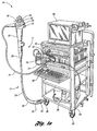
Figure 1a illustrates anendoscopic system 10 comprising anendoscope 11 in accordance with one embodiment of the present Invention. In this embodiment, theendoscope 11 comprises aninsertion tube 12 to be inserted into a body cavity for various endoscopic procedures including gastroscopy, sigmoidoscopy and colonoscopy, esophago gastro duodenoscopy (EGD), endoscopic retrograde cholanglopancreatography (ERCP), and bronchoscopy. As shown, theendoscope 11 comprises aninsertion tube 12 having a plurality of channel ports 13 through which endoscopic units may be disposed. In one embodiment, endoscopic units disposed in one of the ports may include one embodiment of an improved elevator having a tip. - As shown in
Figures 1a and1b , theendoscope 11 further include acontrol system 14 that is in mechanical and fluid communication with theinsertion tube 12. Thecontrol system 14 is configured to control theInsertion tube 12 and endoscopic parts disposed therein. As shown, thecontrol system 14 includes first and second control knobs 16, 18. The control knobs 16, 18 are configured to be in mechanical communication with theinsertion tube 12. The control knobs 16, 18 allow the physician to control and guide, by known means, theinsertion tube 12 through vessels and cavities of a patient. Thecontrol system 14 further includes valve switches (e.g.,suction valve 20, air/water valve 21, camera valve 22), each of which are in communication to one of the channel ports 13 of theinsertion tube 12. For example, thesuction valve switch 20, when activated, allows a vacuum from a suction source through a suction channel port for suctioning unwanted plaque and debris from the patient. In one example, the distal end of theinsertion tube 12 is inserted, rectally or orally, to a predetermined endoscopic location within a patient. Insertion of theinsertion tube 12 may be rectally or orally depending on the endoscopic procedure. The endoscope in combination with the elevator having the tip reduce the risk of damage, e.g., tearing or scraping, of the wire guide. - In this embodiment, the
insertion tube 12 comprises an operatingportion 25 connected to thecontrol system 14 and extending to an insertionportion protecting member 26. Acontrol system 20 is connected to the operatingportion 25 and is configured to control theinsertion tube 12. In this embodiment, theinsertion tube 12 is composed of components that include aflexible tube 28, aflexure 29 connected to theflexible tube 28, and anendoscope tip 30 connect to theflexure 29. Auniversal cord 31, on one end, is connected and in communication with thecontrol system 20. On the other end, thecord 31 has aconnector 18 attached thereto. Theconnector 18 is in communication to a light guide tube and electrical contact, and is connected to alight source apparatus 32 and an image processing apparatus 33 (external devices). These external devices may include amonitor 34, aninput keyboard 35, asuction pump apparatus 36, and anirrigation bottle 37, and other suitable apparatus are installed on arack 39 equipped withcarriers 38. - As shown in
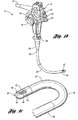
Figures 1c and2 , a concave,depressed cutout 40 is formed on the outer circumferential surface of thetip 30. In this embodiment, achannel opening 42 is formed on one side of thecutout 40, and anobjective lens 44 and alight source 46 are disposed on another side of thecutout 40 for imaging. Both theobjective lens 44 and thelight source 46 are positioned adjacent to thechannel opening 42. Thetip 30 further comprises anozzle 48 extending from aback wall surface 50 of thecutout 40. Thenozzle 48 allows a stream of water, air, or the like to spray towards the outer surface of theobjective lens 44 to clean the lens surface. - As depicted in
Figures 2 and 3 ,tip 30 further includes aguide catheter 52 and awire guide 56 disposed through theguide catheter 52. Thetip 30 further includes anelevator 43 configured to receive the guide catheter and/or wire guide for elevating theguide catheter 52 orwire guide 56. As will be described in greater detail below, theelevator 43 includes adistal tip 112 disposed thereon. Thedistal tip 112 comprises aids to reduce the risk of damage, e.g., tearing or scraping, the wire guide. Thedistal tip 112 comprises abody 113 having lateral ridges orribs 114 to aid in reducing the risk of damage to the wire guide. - In one embodiment, the
elevator 43 is formed from an elastomeric material to prevent stripping of instruments used with the endoscope. In addition to preventing stripping, the elastomeric elevator allows a clinician to more firmly grasp and secure the distal end of an instrument or wire guide relative to the endoscope as compared to endoscopes having rigid elevators. For example, the elastomeric elevator can be formed from rubber. To avoid further stripping or otherwise damaging an instrument or wire guide, cuff can be provided with an elastomeric outer surface. -
Figures 2 and 3 illustrate that theendoscope tip 30 includes acuff 60 as the main body of thetip 30, and a sleeve or cover 62 that covers the perimeter of thecuff 60. As shown, thecover 62 is formed using a nonconductive member such as any suitable polymeric material, e.g., high density polyethylene or polypropylene. In this embodiment, thecover 62 is attached to thecuff 60 by any suitable means, e.g., by adhesive bonding. Thecuff 60 is in fluid communication with the workingchannel 63, which acts as a passageway for the insertion of the device, e.g., wire guide or catheter. Preferably, apassageway 64 is formed therethrough having anaccommodation space 65 formed adjacent thecuff 60 and thetip cover 62. - In this embodiment, a
channel 67 is formed through thetip 30 such that the tip opening of the treatment instrument is able to be disposed through thechannel 63 defining an opening in theaccommodation space 65. As shown inFigure 3 , theaccommodation space 65 houses anelevator 43. Theelevator 43 is used to orient medical instruments such as a catheter (depicted inFigure 2 ), or forceps, extending distally within the workingchannel 63. Theelevator 43 preferably is also used to secure the distal end of the medical instrument or wire guide relative to the endoscope. Aguide plane 69 for guiding a treatment instrument is formed from a groove with any desired shape formed In thetreatment instrument elevator 43 to provide a connection with theinsertion guide passage 64. As shown inFigure 3 , theelevator turning support 68 is located off-center relative to the tip opening of thepassageway 64. Theelevator 43 is mounted such that the distal portion of the elevator pivots or rotates across within theaccommodation space 65. - In another embodiment,
Figure 4 illustrates theelevator 43 having atransverse passageways optional metal sleeves elevator 43 is attached so as to pivot around theelevator turning support 68 provided to thecuff 60. -
Figure 3 further illustrates anelevator wire 90 connected to theelevator 43. In this embodiment, theelevator wire 90 is located at the operatingportion 25 and extends through aguide tube 92 and aguide pipe 91 connected to theguide tube 92. Theelevator wire 90 is in mechanical communication with thecontrol system 14 so that manipulations at thecontrol system 14 result in movement of theelevator wire 90 relative to the endoscope.Figure 3 depicts (in phantom) movement of theelevator 43 when theelevator wire 90 is actuated at thecontrol system 14, moving the position of theelevator 43 about theelevator turning support 68 as theelevator wire 90 is retracted or pulled. - In this embodiment, the
elevator 43 is rotated about theelevator turning support 68 by manipulating or actuating thecontrol system 14 to pull or retract theelevator wire 90. As shown inFigure 5 , the result moves thewire guide 56 in the direction of the arrow P and pushes theelevator 43 against thecuff 60. Because thewire guide 56 is formed from a relatively axially stiff material, it tends to remain straight when pushed against thecuff 60, creating a reactive force in the direction of the arrow Fr inFigure 5 . By means of this reactive force, thewire guide 56 is pressed against the wireguide catch groove 59 depicted inFigure 3 . Moreover, as theelevator 43 and thecuff 60 compress against one another, the wire guide is secured. -
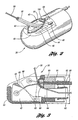
Figure 6 illustrates theelevator 43 comprising atip 112 disposed on theelevator 43 in accordance with one embodiment of the present invention. In this embodiment, thetip 112 is disposed over theelevator 43 and adhered thereon by any suitable means, e.g., sonic bonding, thermal bonding, or adhesive bonding. As shown, thetip 112 comprises abody 113 having a plurality of lateral ridges orribs 114 formed thereon. Thebody 113 has an opening formed and is disposed over theelevator 43 with thelateral ridges 114 positioned thereacross to receive and contact the device. - As shown in
Figures 6 and 7 , thelateral ridges 114 are configured to contact and engage the device, e.g., wire guide or catheter, within the endoscope during usage thereof. Thelateral ridges 114 aid in retaining and guiding thewire guide 56, while also reducing the risk of damage to the wire guide. This is accomplished due to the lateral structure of theridges 113 and the composition thereof. Theridges 114 may take on any desirable or suitable formation to contact the device (e.g. wire guide). - In addition to reducing the risk of damage, the
tip 112 allows a physician to more firmly grasp and secure the distal end of an instrument or wire guide relative to the endoscope as compared to endoscopes having bare, rigid elevators. To avoid further stripping or otherwise damaging an instrument or wire guide,cuff 60 can be provided with an elastomericouter surface 66. - Moreover, the
lateral ridges 114 may be made of any suitable material including elastomeric and polymeric materials, e.g., polytetrafluoroethylene (PTFE), polyethylene, polypropylene, perfluoroelastomer, fluoroelastomer, nitrile, neoprene, polyurethane, silicone, polytetrafluroethylene, styrene-butadiene, rubber, or polyisobutylene. Thetip 112 may be made of any suitable material that will cooperate with the device to absorb and deform when in contact therewith, thereby reducing the risk of damage to the wire guide. -
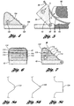
Figures 8a-8c further illustrate various configurations of ridges orribs ridges 114 may take on any desirable or suitable shape for contact with the wire guide. As shown inFigures 8a-8c for example, theridges Figure 8a ), triangular (Figure 8b ), or rectangular (Figure 8c ). - In yet another embodiment,
Figure 9 illustrates theelevator 43 comprising agrasping slot 130 in accordance with one embodiment of the present invention. The grasping slot may take on any suitable shaped or form for grasping of a medical device. In this embodiment, the graspingslot 130 is narrowly formed byinner sides 132 that define thegrasping slot 130 through theelevator 43. Preferably, the graspingslot 130 is centrally formed through theelevator 43 for receiving a medical device (e.g., catheter or wire guide) and grasping the device during operation of the endoscope. -
Figures 9 and 10 illustrate the elevator havinginner sides 132 in accordance with one embodiment of the present invention. As shown,inner sides 132 includeside grasping members 134 formed thereon. In this embodiment,side grasping members 134 are ridges or ribs that are oppositely formed laterally across each of the inner sides. Of course, the side grasping members may be formed on either or both of the inner sides, in any suitable shape, and in staggered configuration. For example, the inner grasping members may be formed longitudinally or in different patterns without falling beyond the scope or spirit of the present invention. - In use, the control system of the endoscope may be manipulated to actuate the elevator, moving the elevator to engage the medical device, e.g., catheter or wire guide. By force, the medical device is worked through the grasping
slot 130 of theelevator 43, thereby engaging the medical device with theinner sides 132 of theelevator 43. Theside grasping members 134 engage the device and, due to the polymeric material of theelevator 43, partially deform and absorb the device to reduce the risk of scraping thereof. In use, theside grasping members 134 receive the medical device when disposed within the slot for enhanced grasping and reduced risk of scraping of the medical device. - In addition to reducing the risk of damage, the formation of the slot allows a physician to more firmly grasp and secure the distal end of an instrument or wire guide relative to other endoscope. To avoid further stripping or otherwise damaging an instrument or wire guide,
cuff 60 can be provided with an elastomericouter surface 66. -
Figures 11a-11c further illustrate various configurations of graspingslots Figure 11a , the graspingslot 140 ofelevator 141 may have a cross-sectional shape that is semi-circular or arcuate. In this embodiment, the graspingslot 140 has anarcuate side 142 that defines thegrasping slot 140. As shown, thearcuate side 142 includes graspingmembers 144 formed thereon for grasping the medical device. -
Figure 11b illustrates graspingslot 150 ofelevator 151 in accordance with another embodiment of the present invention. As shown, the graspingslot 150 has inner andarcuate sides 152 that define theslot 150. In this embodiment, thesides 152 include graspingmember 154 formed thereon for grasping the medical device. -
Figure 11c illustrates graspingslot 160 ofelevator 161 in accordance with yet another embodiment of the present invention. As shown, the graspingslot 160 has tapered andarcuate sides 162 that define theslot 160. In this embodiment, thesides 162 include graspingmembers 164 formed thereon for grasping the medical device. - While the present invention has been described in terms of preferred embodiments, it will be understood, of course, that the invention is not limited thereto since modifications may be made to those skilled in the art, particularly in light of the foregoing teachings.
Claims (15)
- A grasping apparatus for use with an elevator of an endoscope having enhanced grasping features for grasping an elongate medical device, the apparatus comprising:a body comprising a grasping polymeric tip an opening formed through the grasping tip configured to receive the elevator, the grasping tip comprising a plurality of ridges, the plurality of ridges of the grasping tip being configured for grasping of the elongate medical device.
- The apparatus of claim 1 wherein the polymeric material includes at least one of the following components: polytetrafluoroethylene, polyethylene, polypropylene, perfluoroelastomer, fluoroelastomer, nitrile, neoprene, polyurethane, silicone, polytetrafluroethylene, styrene-butadiene, rubber, and polyisobutylene.
- The apparatus of claim 1 wherein each ridge has a predetermined shape for enhanced grasping and reduced scraping of the medical device.
- The apparatus of claim 3 wherein the predetermined shape includes at least one of the following shapes: triangular, semi-circular, and rectangular.
- The apparatus of claim 1 wherein the ridges are formed laterally across the body relative to the elevator.
- The apparatus of claim 1 wherein the ridges are formed longitudinally across the body relative to the elevator.
- The apparatus of claim 1 wherein the body comprises a lip defining the opening through which the elevator is to be received.
- An endoscopic grasping assembly, the assembly comprising:an insertion tube extending to a distal tip having an elevator and a control system in communication with the insertion tube and the elevator for movement of the insertion tube and elevator during operation of the endoscope; and apparatus according to any one of the preceding claims, said elevator being received within the opening of said body.
- The assembly of claim 8 wherein the grasping tip is disposed on the elevator with adhesive.
- The assembly of claim 8 wherein the elevator is comprised of elastomeric material.
- The assembly of claim 8 wherein the grasping tip and opening of the body cooperates with the elevator of the endoscope for enhanced grasping of the elongate medical device.
- An endoscopic apparatus having enhanced features for receiving an elongate medical device, the apparatus comprising:an elevator having a grasping slot formed therethrough and defined by an inner surface, the inner surface having a plurality of grasping members formed thereon and projecting into the grasping slot, the grasping members comprising a plurality of ridges extending laterally across the inner surface, the plurality of ridges being oriented in a staggered configuration the slot being configured to receive the elongate medical device, the grasping member being configured for enhanced grasping of the elongate medical device.
- The apparatus of claim 12 further comprising:an insertion tube extending to a distal tip to which the elevator is pivotally attached; anda control system in communication with the insertion tube and the elevator for movement of the insertion tube and elevator during operation of the endoscope.
- The apparatus of claim 12 wherein the elevator comprises at least one of the following components: polytetrafluoroethylene, polyethylene, polypropylene, perfluoroelastomer, fluoroelastomer, nitrile, neoprene, polyurethane, silicone, polytetrafluroethylene, styrene-butadiene, rubber, and polyisobutylene.
- The apparatus of claim 12 wherein the grasping slot has a predetermined shape defined by the inner side having the at least one grasping member for enhanced grasping and reduced scraping of the medical device.
Applications Claiming Priority (4)
| Application Number | Priority Date | Filing Date | Title |
|---|---|---|---|
| US67195105P | 2005-04-15 | 2005-04-15 | |
| US77918106P | 2006-03-03 | 2006-03-03 | |
| US77918206P | 2006-03-03 | 2006-03-03 | |
| PCT/US2006/014130 WO2006113465A1 (en) | 2005-04-15 | 2006-04-14 | Endoscopic apparatus having an elevator |
Publications (2)
| Publication Number | Publication Date |
|---|---|
| EP1871215A1 EP1871215A1 (en) | 2008-01-02 |
| EP1871215B1 true EP1871215B1 (en) | 2010-03-31 |
Family
ID=36646035
Family Applications (1)
| Application Number | Title | Priority Date | Filing Date |
|---|---|---|---|
| EP06750220A Active EP1871215B1 (en) | 2005-04-15 | 2006-04-14 | Endoscopic apparatus having an elevator |
Country Status (8)
| Country | Link |
|---|---|
| US (1) | US7691055B2 (en) |
| EP (1) | EP1871215B1 (en) |
| JP (1) | JP5007298B2 (en) |
| AT (1) | ATE462349T1 (en) |
| AU (1) | AU2006236619B2 (en) |
| CA (1) | CA2604938A1 (en) |
| DE (1) | DE602006013294D1 (en) |
| WO (1) | WO2006113465A1 (en) |
Families Citing this family (21)
| Publication number | Priority date | Publication date | Assignee | Title |
|---|---|---|---|---|
| JP4754871B2 (en) * | 2005-05-11 | 2011-08-24 | オリンパスメディカルシステムズ株式会社 | End of the endoscope |
| CA2645011A1 (en) * | 2006-03-03 | 2007-09-13 | Wilson-Cook Medical, Inc. | Endoscopic elevator apparatus |
| CA2645671A1 (en) | 2006-03-03 | 2007-09-13 | Wilson-Cook Medical, Inc. | Endoscopic apparatus having an improved catheter |
| US7993287B2 (en) | 2006-03-03 | 2011-08-09 | Cook Medical Technologies Llc | Endoscopic wire guide |
| JP4970877B2 (en) * | 2006-05-17 | 2012-07-11 | オリンパスメディカルシステムズ株式会社 | Endoscope |
| US8109957B2 (en) | 2006-06-30 | 2012-02-07 | Depuy Spine, Inc. | Disc nucleus removal devices and methods |
| US7976458B2 (en) * | 2006-12-05 | 2011-07-12 | Ethicon Endo-Surgery, Inc. | Independent articulating accessory channel |
| JP4847354B2 (en) * | 2007-01-22 | 2011-12-28 | オリンパスメディカルシステムズ株式会社 | Endoscopic treatment tool |
| US8007432B2 (en) * | 2007-01-26 | 2011-08-30 | Ethicon Endo-Surgery, Inc. | Endoscopic accessory control mechanism |
| US8435170B2 (en) * | 2008-01-11 | 2013-05-07 | Boston Scientific Scimed, Inc. | Positioning system for securing a treatment instrument at the end of a medical device |
| US8696550B2 (en) * | 2009-12-18 | 2014-04-15 | Cook Medical Technologies Llc | Endoscope sheath |
| JP2012090949A (en) * | 2010-09-27 | 2012-05-17 | Terumo Corp | Guide wire for endoscope |
| JP6204085B2 (en) | 2013-06-27 | 2017-09-27 | オリンパス株式会社 | Endoscopic treatment tool and endoscope system |
| US11234581B2 (en) * | 2014-05-02 | 2022-02-01 | Endochoice, Inc. | Elevator for directing medical tool |
| EP3178405B1 (en) * | 2014-08-07 | 2018-11-28 | Olympus Corporation | Puncture needle for endoscope |
| CN113143174A (en) * | 2015-07-21 | 2021-07-23 | 图像科学有限责任公司 | Endoscopic accessory with angularly adjustable exit port |
| AU2018227532B2 (en) | 2017-03-03 | 2023-06-01 | Boston Scientific Scimed, Inc. | Device tip |
| WO2020054371A1 (en) * | 2018-09-10 | 2020-03-19 | 富士フイルム株式会社 | Endoscope |
| JP7141963B2 (en) * | 2019-03-01 | 2022-09-26 | 富士フイルム株式会社 | Endoscope |
| JP7282240B2 (en) * | 2019-03-01 | 2023-05-26 | 富士フイルム株式会社 | Endoscope |
| WO2023212736A2 (en) * | 2022-04-29 | 2023-11-02 | Loma Linda University | Periscope device for forward viewing with a duodenoscope |
Family Cites Families (16)
| Publication number | Priority date | Publication date | Assignee | Title |
|---|---|---|---|---|
| US4407273A (en) | 1981-02-25 | 1983-10-04 | Kabushiki Kaisha Medos Kenkyusho | Raising means for guiding an implement of an endoscope |
| JPS57188231A (en) * | 1981-05-14 | 1982-11-19 | Olympus Optical Co | Treating tool guide apparatus of endoscope |
| US5343853A (en) * | 1991-09-20 | 1994-09-06 | Fuji Photo Optical Co., Ltd. | Side-looking type electronic endoscope which allows manipulating tool to be inserted thereinto |
| AU676208B2 (en) * | 1992-11-18 | 1997-03-06 | Ethicon Inc. | Atraumatic endoscopic apparatus |
| US5460168A (en) * | 1992-12-25 | 1995-10-24 | Olympus Optical Co., Ltd. | Endoscope cover assembly and cover-system endoscope |
| US5569157A (en) | 1993-05-07 | 1996-10-29 | Olympus Optical Co., Ltd. | Endoscope |
| US5386818A (en) | 1993-05-10 | 1995-02-07 | Schneebaum; Cary W. | Laparoscopic and endoscopic instrument guiding method and apparatus |
| JP3574530B2 (en) | 1996-05-13 | 2004-10-06 | ペンタックス株式会社 | Endoscope treatment tool guide |
| US5746694A (en) | 1996-05-16 | 1998-05-05 | Wilk; Peter J. | Endoscope biopsy channel liner and associated method |
| US5921971A (en) | 1996-09-13 | 1999-07-13 | Boston Scientific Corporation | Single operator exchange biliary catheter |
| US5899850A (en) | 1997-04-03 | 1999-05-04 | Asahi Kogaku Kogyo Kabushiki Kaisha | Treatment accessories for an endoscope |
| JP3634671B2 (en) * | 1999-06-21 | 2005-03-30 | ペンタックス株式会社 | Endoscope |
| JP4716594B2 (en) * | 2000-04-17 | 2011-07-06 | オリンパス株式会社 | Endoscope |
| US6582357B2 (en) * | 2000-05-24 | 2003-06-24 | Pentax Corporation | Treating instrument erecting device for use in endoscope |
| JP3772107B2 (en) * | 2001-10-12 | 2006-05-10 | オリンパス株式会社 | Endoscope system |
| JP4163438B2 (en) * | 2002-04-17 | 2008-10-08 | オリンパス株式会社 | Endoscope |
-
2006
- 2006-04-14 WO PCT/US2006/014130 patent/WO2006113465A1/en active Application Filing
- 2006-04-14 JP JP2008506751A patent/JP5007298B2/en active Active
- 2006-04-14 AU AU2006236619A patent/AU2006236619B2/en not_active Ceased
- 2006-04-14 DE DE602006013294T patent/DE602006013294D1/en active Active
- 2006-04-14 AT AT06750220T patent/ATE462349T1/en not_active IP Right Cessation
- 2006-04-14 CA CA002604938A patent/CA2604938A1/en not_active Abandoned
- 2006-04-14 US US11/404,554 patent/US7691055B2/en active Active
- 2006-04-14 EP EP06750220A patent/EP1871215B1/en active Active
Also Published As
| Publication number | Publication date |
|---|---|
| AU2006236619A1 (en) | 2006-10-26 |
| CA2604938A1 (en) | 2006-10-26 |
| ATE462349T1 (en) | 2010-04-15 |
| AU2006236619B2 (en) | 2012-02-02 |
| WO2006113465A1 (en) | 2006-10-26 |
| US20060235271A1 (en) | 2006-10-19 |
| EP1871215A1 (en) | 2008-01-02 |
| US7691055B2 (en) | 2010-04-06 |
| JP2008536579A (en) | 2008-09-11 |
| DE602006013294D1 (en) | 2010-05-12 |
| JP5007298B2 (en) | 2012-08-22 |
Similar Documents
| Publication | Publication Date | Title |
|---|---|---|
| EP1871215B1 (en) | Endoscopic apparatus having an elevator | |
| US7794389B2 (en) | Endoscopic elevator apparatus | |
| JP5231258B2 (en) | Endoscopic device with improved catheter | |
| US8475360B2 (en) | Endoscopic apparatus having an expandable balloon delivery system | |
| US8945153B2 (en) | Endoscopic apparatus having a clip device | |
| US20070208220A1 (en) | Endoscopic delivery apparatus having a catheter with radial grooves | |
| AU2007257793B2 (en) | Endoscopic apparatus having an expandable balloon delivery system | |
| US7993287B2 (en) | Endoscopic wire guide | |
| US9844649B2 (en) | Telescopic wire guide |
Legal Events
| Date | Code | Title | Description |
|---|---|---|---|
| PUAI | Public reference made under article 153(3) epc to a published international application that has entered the european phase |
Free format text: ORIGINAL CODE: 0009012 |
|
| 17P | Request for examination filed |
Effective date: 20071026 |
|
| AK | Designated contracting states |
Kind code of ref document: A1 Designated state(s): AT BE BG CH CY CZ DE DK EE ES FI FR GB GR HU IE IS IT LI LT LU LV MC NL PL PT RO SE SI SK TR |
|
| 17Q | First examination report despatched |
Effective date: 20080214 |
|
| DAX | Request for extension of the european patent (deleted) | ||
| RTI1 | Title (correction) |
Free format text: ENDOSCOPIC APPARATUS HAVING AN ELEVATOR |
|
| GRAP | Despatch of communication of intention to grant a patent |
Free format text: ORIGINAL CODE: EPIDOSNIGR1 |
|
| GRAS | Grant fee paid |
Free format text: ORIGINAL CODE: EPIDOSNIGR3 |
|
| GRAA | (expected) grant |
Free format text: ORIGINAL CODE: 0009210 |
|
| AK | Designated contracting states |
Kind code of ref document: B1 Designated state(s): AT BE BG CH CY CZ DE DK EE ES FI FR GB GR HU IE IS IT LI LT LU LV MC NL PL PT RO SE SI SK TR |
|
| REG | Reference to a national code |
Ref country code: GB Ref legal event code: FG4D Ref country code: CH Ref legal event code: EP |
|
| REG | Reference to a national code |
Ref country code: IE Ref legal event code: FG4D |
|
| REF | Corresponds to: |
Ref document number: 602006013294 Country of ref document: DE Date of ref document: 20100512 Kind code of ref document: P |
|
| REG | Reference to a national code |
Ref country code: NL Ref legal event code: VDEP Effective date: 20100331 |
|
| PG25 | Lapsed in a contracting state [announced via postgrant information from national office to epo] |
Ref country code: LT Free format text: LAPSE BECAUSE OF FAILURE TO SUBMIT A TRANSLATION OF THE DESCRIPTION OR TO PAY THE FEE WITHIN THE PRESCRIBED TIME-LIMIT Effective date: 20100331 |
|
| LTIE | Lt: invalidation of european patent or patent extension |
Effective date: 20100331 |
|
| PG25 | Lapsed in a contracting state [announced via postgrant information from national office to epo] |
Ref country code: SI Free format text: LAPSE BECAUSE OF FAILURE TO SUBMIT A TRANSLATION OF THE DESCRIPTION OR TO PAY THE FEE WITHIN THE PRESCRIBED TIME-LIMIT Effective date: 20100331 Ref country code: LV Free format text: LAPSE BECAUSE OF FAILURE TO SUBMIT A TRANSLATION OF THE DESCRIPTION OR TO PAY THE FEE WITHIN THE PRESCRIBED TIME-LIMIT Effective date: 20100331 Ref country code: PL Free format text: LAPSE BECAUSE OF FAILURE TO SUBMIT A TRANSLATION OF THE DESCRIPTION OR TO PAY THE FEE WITHIN THE PRESCRIBED TIME-LIMIT Effective date: 20100331 Ref country code: FI Free format text: LAPSE BECAUSE OF FAILURE TO SUBMIT A TRANSLATION OF THE DESCRIPTION OR TO PAY THE FEE WITHIN THE PRESCRIBED TIME-LIMIT Effective date: 20100331 Ref country code: AT Free format text: LAPSE BECAUSE OF FAILURE TO SUBMIT A TRANSLATION OF THE DESCRIPTION OR TO PAY THE FEE WITHIN THE PRESCRIBED TIME-LIMIT Effective date: 20100331 |
|
| PG25 | Lapsed in a contracting state [announced via postgrant information from national office to epo] |
Ref country code: SE Free format text: LAPSE BECAUSE OF FAILURE TO SUBMIT A TRANSLATION OF THE DESCRIPTION OR TO PAY THE FEE WITHIN THE PRESCRIBED TIME-LIMIT Effective date: 20100331 Ref country code: RO Free format text: LAPSE BECAUSE OF FAILURE TO SUBMIT A TRANSLATION OF THE DESCRIPTION OR TO PAY THE FEE WITHIN THE PRESCRIBED TIME-LIMIT Effective date: 20100331 Ref country code: CY Free format text: LAPSE BECAUSE OF FAILURE TO SUBMIT A TRANSLATION OF THE DESCRIPTION OR TO PAY THE FEE WITHIN THE PRESCRIBED TIME-LIMIT Effective date: 20100331 Ref country code: BE Free format text: LAPSE BECAUSE OF FAILURE TO SUBMIT A TRANSLATION OF THE DESCRIPTION OR TO PAY THE FEE WITHIN THE PRESCRIBED TIME-LIMIT Effective date: 20100331 Ref country code: NL Free format text: LAPSE BECAUSE OF FAILURE TO SUBMIT A TRANSLATION OF THE DESCRIPTION OR TO PAY THE FEE WITHIN THE PRESCRIBED TIME-LIMIT Effective date: 20100331 Ref country code: ES Free format text: LAPSE BECAUSE OF FAILURE TO SUBMIT A TRANSLATION OF THE DESCRIPTION OR TO PAY THE FEE WITHIN THE PRESCRIBED TIME-LIMIT Effective date: 20100712 Ref country code: EE Free format text: LAPSE BECAUSE OF FAILURE TO SUBMIT A TRANSLATION OF THE DESCRIPTION OR TO PAY THE FEE WITHIN THE PRESCRIBED TIME-LIMIT Effective date: 20100331 |
|
| PG25 | Lapsed in a contracting state [announced via postgrant information from national office to epo] |
Ref country code: IS Free format text: LAPSE BECAUSE OF FAILURE TO SUBMIT A TRANSLATION OF THE DESCRIPTION OR TO PAY THE FEE WITHIN THE PRESCRIBED TIME-LIMIT Effective date: 20100731 Ref country code: CZ Free format text: LAPSE BECAUSE OF FAILURE TO SUBMIT A TRANSLATION OF THE DESCRIPTION OR TO PAY THE FEE WITHIN THE PRESCRIBED TIME-LIMIT Effective date: 20100331 Ref country code: MC Free format text: LAPSE BECAUSE OF NON-PAYMENT OF DUE FEES Effective date: 20100430 Ref country code: SK Free format text: LAPSE BECAUSE OF FAILURE TO SUBMIT A TRANSLATION OF THE DESCRIPTION OR TO PAY THE FEE WITHIN THE PRESCRIBED TIME-LIMIT Effective date: 20100331 |
|
| REG | Reference to a national code |
Ref country code: CH Ref legal event code: PL |
|
| PG25 | Lapsed in a contracting state [announced via postgrant information from national office to epo] |
Ref country code: DK Free format text: LAPSE BECAUSE OF FAILURE TO SUBMIT A TRANSLATION OF THE DESCRIPTION OR TO PAY THE FEE WITHIN THE PRESCRIBED TIME-LIMIT Effective date: 20100331 Ref country code: PT Free format text: LAPSE BECAUSE OF FAILURE TO SUBMIT A TRANSLATION OF THE DESCRIPTION OR TO PAY THE FEE WITHIN THE PRESCRIBED TIME-LIMIT Effective date: 20100802 |
|
| PLBE | No opposition filed within time limit |
Free format text: ORIGINAL CODE: 0009261 |
|
| STAA | Information on the status of an ep patent application or granted ep patent |
Free format text: STATUS: NO OPPOSITION FILED WITHIN TIME LIMIT |
|
| PG25 | Lapsed in a contracting state [announced via postgrant information from national office to epo] |
Ref country code: LI Free format text: LAPSE BECAUSE OF NON-PAYMENT OF DUE FEES Effective date: 20100430 Ref country code: CH Free format text: LAPSE BECAUSE OF NON-PAYMENT OF DUE FEES Effective date: 20100430 |
|
| 26N | No opposition filed |
Effective date: 20110104 |
|
| PG25 | Lapsed in a contracting state [announced via postgrant information from national office to epo] |
Ref country code: IT Free format text: LAPSE BECAUSE OF FAILURE TO SUBMIT A TRANSLATION OF THE DESCRIPTION OR TO PAY THE FEE WITHIN THE PRESCRIBED TIME-LIMIT Effective date: 20100331 |
|
| REG | Reference to a national code |
Ref country code: GB Ref legal event code: 732E Free format text: REGISTERED BETWEEN 20110804 AND 20110810 |
|
| REG | Reference to a national code |
Ref country code: FR Ref legal event code: ST Effective date: 20111125 |
|
| PG25 | Lapsed in a contracting state [announced via postgrant information from national office to epo] |
Ref country code: FR Free format text: LAPSE BECAUSE OF NON-PAYMENT OF DUE FEES Effective date: 20100531 |
|
| PG25 | Lapsed in a contracting state [announced via postgrant information from national office to epo] |
Ref country code: HU Free format text: LAPSE BECAUSE OF FAILURE TO SUBMIT A TRANSLATION OF THE DESCRIPTION OR TO PAY THE FEE WITHIN THE PRESCRIBED TIME-LIMIT Effective date: 20101001 Ref country code: LU Free format text: LAPSE BECAUSE OF NON-PAYMENT OF DUE FEES Effective date: 20100414 Ref country code: BG Free format text: LAPSE BECAUSE OF FAILURE TO SUBMIT A TRANSLATION OF THE DESCRIPTION OR TO PAY THE FEE WITHIN THE PRESCRIBED TIME-LIMIT Effective date: 20100331 |
|
| PG25 | Lapsed in a contracting state [announced via postgrant information from national office to epo] |
Ref country code: TR Free format text: LAPSE BECAUSE OF FAILURE TO SUBMIT A TRANSLATION OF THE DESCRIPTION OR TO PAY THE FEE WITHIN THE PRESCRIBED TIME-LIMIT Effective date: 20100331 |
|
| PG25 | Lapsed in a contracting state [announced via postgrant information from national office to epo] |
Ref country code: BG Free format text: LAPSE BECAUSE OF FAILURE TO SUBMIT A TRANSLATION OF THE DESCRIPTION OR TO PAY THE FEE WITHIN THE PRESCRIBED TIME-LIMIT Effective date: 20100630 |
|
| PG25 | Lapsed in a contracting state [announced via postgrant information from national office to epo] |
Ref country code: GR Free format text: LAPSE BECAUSE OF FAILURE TO SUBMIT A TRANSLATION OF THE DESCRIPTION OR TO PAY THE FEE WITHIN THE PRESCRIBED TIME-LIMIT Effective date: 20100331 |
|
| PGFP | Annual fee paid to national office [announced via postgrant information from national office to epo] |
Ref country code: IE Payment date: 20230327 Year of fee payment: 18 |
|
| PGFP | Annual fee paid to national office [announced via postgrant information from national office to epo] |
Ref country code: GB Payment date: 20230315 Year of fee payment: 18 |
|
| P01 | Opt-out of the competence of the unified patent court (upc) registered |
Effective date: 20230602 |
|
| PGFP | Annual fee paid to national office [announced via postgrant information from national office to epo] |
Ref country code: DE Payment date: 20230320 Year of fee payment: 18 |