EP1857825A1 - Measuring apparatus - Google Patents
Measuring apparatus Download PDFInfo
- Publication number
- EP1857825A1 EP1857825A1 EP07008171A EP07008171A EP1857825A1 EP 1857825 A1 EP1857825 A1 EP 1857825A1 EP 07008171 A EP07008171 A EP 07008171A EP 07008171 A EP07008171 A EP 07008171A EP 1857825 A1 EP1857825 A1 EP 1857825A1
- Authority
- EP
- European Patent Office
- Prior art keywords
- switch
- current
- insulation resistance
- iso
- arrangement according
- Prior art date
- Legal status (The legal status is an assumption and is not a legal conclusion. Google has not performed a legal analysis and makes no representation as to the accuracy of the status listed.)
- Granted
Links
- 238000005259 measurement Methods 0.000 claims abstract description 57
- 238000009413 insulation Methods 0.000 claims abstract description 51
- 239000004065 semiconductor Substances 0.000 claims description 5
- 238000004364 calculation method Methods 0.000 claims description 4
- 238000009434 installation Methods 0.000 claims 1
- 238000002955 isolation Methods 0.000 abstract description 2
- 238000000034 method Methods 0.000 description 8
- 230000006378 damage Effects 0.000 description 6
- 101100125299 Agrobacterium rhizogenes aux2 gene Proteins 0.000 description 4
- 238000012544 monitoring process Methods 0.000 description 4
- 241001295925 Gegenes Species 0.000 description 3
- 239000003990 capacitor Substances 0.000 description 2
- 238000010276 construction Methods 0.000 description 2
- 238000011156 evaluation Methods 0.000 description 2
- 230000000712 assembly Effects 0.000 description 1
- 238000000429 assembly Methods 0.000 description 1
- 239000004020 conductor Substances 0.000 description 1
- 238000011109 contamination Methods 0.000 description 1
- 230000001419 dependent effect Effects 0.000 description 1
- 238000010586 diagram Methods 0.000 description 1
- 230000005669 field effect Effects 0.000 description 1
- 238000013208 measuring procedure Methods 0.000 description 1
- 230000011664 signaling Effects 0.000 description 1
Images


Classifications
-
- G—PHYSICS
- G01—MEASURING; TESTING
- G01R—MEASURING ELECTRIC VARIABLES; MEASURING MAGNETIC VARIABLES
- G01R27/00—Arrangements for measuring resistance, reactance, impedance, or electric characteristics derived therefrom
- G01R27/02—Measuring real or complex resistance, reactance, impedance, or other two-pole characteristics derived therefrom, e.g. time constant
- G01R27/16—Measuring impedance of element or network through which a current is passing from another source, e.g. cable, power line
- G01R27/18—Measuring resistance to earth, i.e. line to ground
-
- Y—GENERAL TAGGING OF NEW TECHNOLOGICAL DEVELOPMENTS; GENERAL TAGGING OF CROSS-SECTIONAL TECHNOLOGIES SPANNING OVER SEVERAL SECTIONS OF THE IPC; TECHNICAL SUBJECTS COVERED BY FORMER USPC CROSS-REFERENCE ART COLLECTIONS [XRACs] AND DIGESTS
- Y02—TECHNOLOGIES OR APPLICATIONS FOR MITIGATION OR ADAPTATION AGAINST CLIMATE CHANGE
- Y02E—REDUCTION OF GREENHOUSE GAS [GHG] EMISSIONS, RELATED TO ENERGY GENERATION, TRANSMISSION OR DISTRIBUTION
- Y02E10/00—Energy generation through renewable energy sources
- Y02E10/50—Photovoltaic [PV] energy
Definitions
- the invention relates to a measuring arrangement with a grounding point for determining the insulation resistance (R iso ) of an electrical device under voltage or a system with a supply voltage (U B ) having a positive pole and a negative pole, wherein two switches (S 1 and S 2 ) or a corresponding switch are present, each of which establish a current path between one of the two poles and the grounding point to determine the occurrence of one or more insulation fault with any potential reference the total resulting insulation resistance (R iso ).
- moisture, contamination, short circuits or other causes may cause insulation faults between a live part of the system and ground.
- R iso always corresponds to the parallel connection of all leakage resistances, while U x or the ratio R n / R p gives an indication of the position of the ground faults.
- isolation errors R p and R n occur at the same time, the method described no longer functions, since only one value R n or R p can be determined in each case.
- a ground fault which arises at a potential other than positive or negative pole, can not be described with an equivalent circuit diagram of only one resistor.
- a low-resistance insulation fault can be better evaluated if, for example, in the case of an insulation fault from positive to earth, the known, high-impedance resistor is switched to the negative pole and vice versa.
- the additional measurement with a closed switch will only be carried out if limit values are already exceeded in the measurement with opened switches.
- Ground faults that do not occur directly at the positive or negative pole, but potentials in between, are not necessarily found with this method. For example, a ground fault in the middle of a photovoltaic generator would not lead to a change in the measured voltage when the switches are open, so that no measurement would be carried out with the switch closed and therefore the ground fault could not be detected.
- the measurement process is generally defined so that one measurement cycle comprises one measurement with two switches open and one measurement with one open and one closed switch.
- the script does not specify which of the two switches should be closed; this decision is made more meaningful, however, as in the DE 35 13 849 met. If one prefers ideal measuring equipment, one could exactly determine any earth faults with this method.
- R L ⁇ 1 R s ⁇ v 1 v 2 ⁇ v 2 ⁇ ' v 1 ⁇ ' - 1
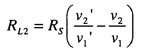
- R L ⁇ 2 R s ⁇ v 2 ⁇ ' v 1 ⁇ ' - v 2 v 1 used.
- the disadvantage is that in order to calculate the leakage resistances R n (R L1 ) and R p (R L2 ) it is necessary to measure two instantaneous values of two different voltages and to know the exact value of the connected resistor. Since all measured variables are subject to a measurement error in practice, the measurement errors of both voltages are included in the calculated resistance values.
- This arrangement is used, for example, in a DC system for the London Underground.
- the invention has for its object to provide a measuring device with which an accurate measurement of the insulation resistance R iso is possible, even if in each case leakage resistance to plus and minus, R p and R n occur simultaneously or a leakage resistance occurs at an intermediate potential. In order to minimize the influence of possible measurement errors, as few as possible measured variables should be used to calculate R iso .
- the measuring procedure is opposite to the procedure EP 0 833 423 modified so that a measurement cycle includes both a measurement with open switch S 1 and closed switch S 2 as well as a measurement with open switch S 2 and closed switch S 1 .
- the other structure can be left unchanged, in particular two high-resistance resistors R S are used with known, equal value in series with the two switches.
- R n R s ⁇ U 1 ⁇ ' U 1 - 1 be determined.
- the unprimed variables U 1 , U 2 represent measured values with the switch S 1 closed and the switch S 2 open, while the canceled variables U1 ', U2' represent the measured values when the switch S 1 is open and the switch S 2 is closed.
- An important advantage of the invention is that a measurement with high accuracy is possible even if multiple leakage resistances are present.
- the measuring arrangement thus works perfectly even if leakage resistances R n and R p occur simultaneously or an insulation fault occurs at a location which is not on the positive or the negative pole, for example in the middle of a solar generator.
- the insulation resistances determined would be higher than actually, so that the user would erroneously weigh in safety. Even with the improved arrangements after EP 1 265 076 .
- a second embodiment of the invention according to claim 3 one can replace the two voltage measuring devices by a single current measuring device between the connection point of the two switches and earth (Fig. 4).
- the two resistors R S are then no longer needed for the measurement, so that their tolerances no longer go into the measurement accuracy.
- the measurement is such that a PE conductor (earth) via a switching element, For example, a relay is connected in succession to the plus and the minus of the supply voltage, now each of the currents are measured in the switched connections.
- An offset error of the current measurement has no influence on the determined R iso value by the difference measurement, so that the measurement accuracy is again improved.
- the complex potential-free current measurement is relocated to one of the two poles of the system, so that the evaluation can be made easier by a microprocessor with a corresponding reference potential (Fig. 5).
- a switch S 2 is not directly connected to a pole, but via a current source that requires a negligible in relation to the operating voltage U B supply voltage.
- a correspondingly controlled transistor for example a bipolar transistor with the highest possible current gain or a field effect transistor.
- the collector or drain terminal of the transistor is connected to the not connected to PE terminal of the second switch S 1 . Between this connection point and the second pole is a current measuring device connected.
- the current I plus can be passed through a shunt which is connected to an A / D converter in the microcontroller. The microcontroller can then take successively the readings for U B , L plus and L plus and calculate R iso .
- the measurement of the insulation resistance in photovoltaic systems for the generation of electrical energy is particularly advantageous. Precise monitoring of ground faults can detect in good time a hazard to persons or sensitive electronic devices, even if several insulation faults occur at different potentials.
- the use of the measuring arrangement according to the invention in transformerless inverters is particularly advantageous.
- low-resistance ground faults are also a danger in the generator center, as this practically short circuits the inverter output.
- the resulting high currents can lead to damage or destruction of the power semiconductors. Damage to the semiconductors of the inverter
- other safety measures such as current monitoring can be avoided, the cause of the fault would not be displayed.
- the search for the error would be tedious and costly if no measurement of the insulation resistance takes place.
- the insulation resistance measurement according to the invention can timely indicate the error and prevent the connection of the inverter to the public grid.
- transformerless inverters can be reliably protected and downtimes effectively shortened by the invention.
- FIG. 1 shows a grid-connected photovoltaic system as an example of a system to be monitored for insulation faults.
- Components of the system are a photovoltaic generator 1 of a plurality of solar cells 2 and an inverter 3, which is connected to an AC voltage network 4, which is connected to the earth 5.
- the system has a positive pole 6 and a negative pole 7.
- the inverter 3 consists for example of a buffer capacitor 8, power semiconductors 9, storage chokes 10 and a device for mains connection 11.
- a leakage resistance R p 12 between positive pole 6 and earth 5 a leakage resistance R n 13 between minus 7 and ground 5 and a leakage resistance R x 14 from any potential to earth 5 located .
- R iso 1 1 R p + 1 R n + 1 R x
- a single insulation fault at the positive or negative pole ie a single leakage resistance R p or R n
- R p or R n can be determined with a simple arrangement according to FIG. 2.
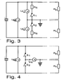
- Fig. 3 shows a first embodiment of the invention.
- the construction shown is also in the EP 0 833 423 used.
- a measurement cycle is defined so that a first measurement with closed switch S 1 and open switch S 2 and then a second measurement with closed switch S 2 and opened switch S 1 is performed. This results, as already stated, simple equations with little error.
- Fig. 4 shows a second embodiment of the invention.
- a current measuring device between ground 5 and the connection point of the two switches is provided to measure the current for calculating the insulation resistance.
- the measuring cycle remains unchanged from the rule for FIG. 3.
- Fig. 5 shows a preferred third embodiment of the invention.
- the circuit uses an additional constant current source, which supplies the constant current I const .
- the switch S 2 is not switched directly to the positive pole, but via the power source.
- a MOSFET with suitable control U G is connected in parallel to the two switches S 1 and S 2 .
- the advantage here is that instead of the current I PE with respect to the earth 5, a current I plus is measured with respect to the positive pole of the system. The current can thus be measured, for example via a shunt, well with a microprocessor whose reference potential lies on this pole. As with the embodiment according to FIG. 4, an accurate measurement without high-precision resistances is possible with this solution.
- the insulation resistance R iso of a live electrical device or a system with a plus pole 6 and a minus pole 7 can thus be determined with the presented method and the described measuring arrangements.
- Both switches S 1 , S 2 each make a current path between ground and one of the two poles 6,7 when closing. With this arrangement, insulation errors at both poles 6,7, on any potentials in between and any combinations of these error cases are detected. The total resulting insulation resistance can be determined very accurately in a simple manner.
Landscapes
- Physics & Mathematics (AREA)
- General Physics & Mathematics (AREA)
- Measurement Of Resistance Or Impedance (AREA)
- Testing Of Short-Circuits, Discontinuities, Leakage, Or Incorrect Line Connections (AREA)
Abstract
Description
Die Erfindung betrifft eine Messanordnung mit einem Erdungspunkt zur Ermittlung des Isolationswiderstandes (Riso) einer unter Spannung stehenden elektrischen Vorrichtung oder einer Anlage mit einer Versorgungsspannung (UB) mit einem Pluspol und einem Minuspol, wobei zwei Schalter (S1 und S2) oder ein entsprechender Umschalter vorhanden sind, die jeweils einen Strompfad zwischen einem der beiden Pole und dem Erdungspunkt herstellen, um bei Auftreten ein oder mehrerer Isolationsfehler mit beliebigem Potentialbezug den sich insgesamt ergebenden Isolationswiderstand (Riso) zu ermitteln.The invention relates to a measuring arrangement with a grounding point for determining the insulation resistance (R iso ) of an electrical device under voltage or a system with a supply voltage (U B ) having a positive pole and a negative pole, wherein two switches (S 1 and S 2 ) or a corresponding switch are present, each of which establish a current path between one of the two poles and the grounding point to determine the occurrence of one or more insulation fault with any potential reference the total resulting insulation resistance (R iso ).
In elektrischen Anlagen können durch Feuchtigkeit, Verschmutzung, Kurzschlüsse oder andere Ursachen Fehler in der Isolation zwischen einem spannungsführenden Anlagenteil und Erde auftreten.In electrical systems, moisture, contamination, short circuits or other causes may cause insulation faults between a live part of the system and ground.
Bei geerdeten elektrischen Anlagen entsteht durch einen solchen Fehler unmittelbar ein Stromfluss in der Erdverbindung, so dass die Isolation z.B. durch eine Strommessung in der Erdverbindung überwacht und der Fehler sofort behoben werden kann. Schwieriger ist die Überwachung in ungeerdeten Geräten oder Anlagen, wo die Erdverbindung erst durch die Verbindung mit einer anderen, geerdeten Anlage (z.B. Zuschaltung auf das öffentliche Netz) oder durch Berührung eines Anlagenteils entsteht. Ein Isolationsfehler führt hier zunächst zu keinem Stromfluss. Wird die Anlage jedoch nun (an einem anderem Punkt) berührt, ist durch die doppelte Verbindung nach Erde ein Stromkreis geschlossen, in dem gefährliche Körperströme fließen können. Ein ähnliches Problem tritt auf, wenn die Anlage mit einer geerdeten Vorrichtung verbunden wird: Hier fließt ein Strom über beide Vorrichtungen und kann diese beschädigen. Um solche Fehler zu vermeiden, ist es sinnvoll, regelmäßig den Isolationswiderstand der Anlage zu messen, damit bei Unterschreiten eines Grenzwertes geeignete Maßnahmen ergriffen werden können.In grounded electrical systems, such a fault causes a direct current flow in the ground connection, so that the insulation is e.g. monitored by a current measurement in the ground connection and the error can be corrected immediately. More difficult is the monitoring in ungrounded devices or systems where the earth connection only arises through the connection to another, earthed system (for example, connection to the public network) or by touching a piece of equipment. An insulation fault initially leads to no current flow. However, if the system is now touched (at a different point), the double connection to earth closes a circuit in which dangerous body currents can flow. A similar problem occurs when the system is connected to a grounded device: a current flows through both devices and can damage them. In order to avoid such errors, it makes sense to regularly measure the insulation resistance of the system so that suitable measures can be taken if a limit value is undershot.
Zur Darstellung des Isolationszustands eines spannungsführenden Gerätes bzw. einer spannungsführenden Anlage sind verschiedene Ersatzschaltbilder (ESB) gebräuchlich. Bei Anlagen, die ausschließlich aus Plus- und Minuspol bestehen, wie z.B. Stromschienensystemen, ist es sinnvoll, alle Erdschlüsse am Pluspol in einem Widerstand Rp und alle Erdschlüsse am Minuspol in einem Widerstand Rn zusammenzufassen (Fig. 2). Bei Vorrichtungen, in denen auch beliebige Zwischenpotentiale auftreten, wie z.B. einem PV-Generator, kann es dagegen sinnvoller sein, ein ESB aus dem Isolationswiderstand Riso und dem Potential Ux, auf dem ein Erdschluss auftritt, zu verwenden. Grundsätzlich sind beide ESB gleichwertig und können ineinander umgerechnet werden, so entspricht z.B. Riso der Parallelschaltung aus Rn und Rp. Auch Fehlerfälle mit mehreren Erdschlüssen auf verschiedenen Potentialen können durch beide ESB erfasst werden. Riso entspricht dabei immer der Parallelschaltung aller Leckwiderstände, während Ux bzw. das Verhältnis Rn/Rp einen Anhaltspunkt für die Lage der Erdschlüsse gibt.To illustrate the insulation state of a live device or a live system different equivalent circuits (ESB) are common. For systems consisting exclusively of positive and negative poles, such as busbar systems, it makes sense to combine all ground faults at the positive terminal in a resistor Rp and all ground faults at the negative terminal in a resistor R n (FIG. 2). In devices in which any intermediate potentials occur, such as a PV generator, it may be more useful to use an ESB from the insulation resistance R iso and the potential U x on which a ground fault occurs. Basically both are ESB Equivalent and can be converted into each other, for example, R iso corresponds to the parallel circuit of R n and R p . Even faults with multiple earth faults at different potentials can be detected by both ESBs. R iso always corresponds to the parallel connection of all leakage resistances, while U x or the ratio R n / R p gives an indication of the position of the ground faults.
Der Isolationswiderstand ist unproblematisch zu messen, wenn nur ein Isolationsfehler Rp zwischen Pluspol und Erde oder ein Isolationsfehler Rn zwischen Minuspol und Erde auftritt. Hierzu muss nur die Erde (PE) jeweils über bekannte, hochohmige Widerstände Raux1, Raux2 mit den beiden Polen verbunden werden und zwei der drei Spannungen
- Pluspol gegen Erde (U1)
- Erde gegen Minuspol (U2)
- Pluspol gegen Minuspol (UB)
- Positive pole against earth (U 1 )
- Earth against negative pole (U 2 )
- Positive pole against negative pole (U B )
Treten gleichzeitig Isolationsfehler Rp und Rn auf, funktioniert das beschriebene Verfahren nicht mehr, da damit jeweils nur ein Wert Rn oder Rp ermittelt werden kann. Auch ein Erdschluss, der auf einem anderen Potential als Plus- oder Minuspol entsteht, kann nicht mit einem Ersatzschaltbild aus nur einem Widerstand beschrieben werden.If isolation errors R p and R n occur at the same time, the method described no longer functions, since only one value R n or R p can be determined in each case. A ground fault, which arises at a potential other than positive or negative pole, can not be described with an equivalent circuit diagram of only one resistor.
In der
Ein niederohmiger Isolationsfehler kann besser ausgewertet werden, wenn z.B. bei einem Isolationsfehler von Plus nach Erde der bekannte, hochohmige Widerstand zum Minuspol geschaltet wird und umgekehrt. In der
In der 
verwendet. Nachteilig ist, dass zur Berechnung der Leckwiderstände Rn (RL1) und Rp (RL2) die Messung von jeweils zwei Momentanwerten zwei verschiedener Spannungen und die Kenntnis des genauen Wertes des zugeschalteten Widerstands nötig ist. Da alle Messgrößen in der Praxis mit einem Messfehler behaftet sind, gehen die Messfehler beider Spannungen in die berechneten Widerstandswerte ein.In the
used. The disadvantage is that in order to calculate the leakage resistances R n (R L1 ) and R p (R L2 ) it is necessary to measure two instantaneous values of two different voltages and to know the exact value of the connected resistor. Since all measured variables are subject to a measurement error in practice, the measurement errors of both voltages are included in the calculated resistance values.
Diese Anordnung wird beispielsweise bei einem DC-System für die Londoner Untergrundbahn eingesetzt.This arrangement is used, for example, in a DC system for the London Underground.
Der Erfindung liegt die Aufgabe zugrunde, eine Messanordnung zu schaffen, mit der eine genaue Messung des Isolationswiderstandes Riso möglich ist, auch wenn jeweils Leckwiderstände nach Plus und nach Minus, Rp und Rn, gleichzeitig auftreten oder ein Leckwiderstand auf einem Zwischenpotential auftritt. Um den Einfluss möglicher Messfehler klein zu halten, sollen dabei möglichst wenige Messgrößen zur Berechnung von Riso herangezogen werden.The invention has for its object to provide a measuring device with which an accurate measurement of the insulation resistance R iso is possible, even if in each case leakage resistance to plus and minus, R p and R n occur simultaneously or a leakage resistance occurs at an intermediate potential. In order to minimize the influence of possible measurement errors, as few as possible measured variables should be used to calculate R iso .
Die Aufgabe wird erfindungsgemäß durch die Merkmale des Anspruches 1 gelöst. Hierzu ist der Messablauf gegenüber dem Verfahren aus
In einer ersten Ausgestaltung der Erfindung gemäß Anspruch 2 kann der sonstige Aufbau unverändert gelassen werden, insbesondere werden zwei hochohmige Widerstände RS mit bekanntem, gleichem Wert in Reihe mit den beiden Schaltern verwendet. Wie leicht herzuleiten und zu überprüfen ist, können die Leckwiderstände Rn und Rp dann über die Beziehungen 

bestimmt werden. Dabei stellen die ungestrichenen Größen U1, U2 Messwerte bei geschlossenem Schalter S1 und geöffnetem Schalter S2 dar, während die gestrichenen Größen U1', U2' für die Messwerte bei geöffnetem Schalter S1 und geschlossenem Schalter S2 stehen.
In der Nomenklatur der 

ergeben. In beide Gleichungen geht jeweils nur noch eine Messgröße und damit nur noch ein Messfehler ein, so dass die Messgenauigkeit verbessert wird. Zur Bestimmung des Wertes für Riso muss in bekannter Weise die Parallelschaltung aus Rn und Rp bestimmt werden.In a first embodiment of the invention according to claim 2, the other structure can be left unchanged, in particular two high-resistance resistors R S are used with known, equal value in series with the two switches. As can easily be deduced and verified, the leakage resistances R n and R p can then be governed by the relationships
be determined. In this case, the unprimed variables U 1 , U 2 represent measured values with the switch S 1 closed and the switch S 2 open, while the canceled variables U1 ', U2' represent the measured values when the switch S 1 is open and the switch S 2 is closed.
In the nomenclature of
result. In both equations in each case only one measurement and thus only one measurement error, so that the measurement accuracy is improved. To determine the value for R iso , the parallel connection of R n and R p must be determined in a known manner.
Durch die erfindungsgemäße Messanordnung ist es möglich, den Isolationswiderstand mit hoher Genauigkeit zu messen. Durch das erfindungsgemäße Schalten der Schalter ergeben sich sehr handliche Gleichungen, die von einer Recheneinheit leicht und schnell berechnet werden können.By measuring arrangement according to the invention, it is possible to measure the insulation resistance with high accuracy. Switching the switches according to the invention results in very handy equations that can be calculated easily and quickly by a computing unit.
Ein wichtiger Vorteil der Erfindung besteht darin, dass eine Messung mit hoher Genauigkeit auch dann möglich ist, wenn mehrere Leckwiderstände vorhanden sind. Die Messanordnung arbeitet also auch dann einwandfrei, wenn Leckwiderstände Rn und Rp gleichzeitig auftreten oder ein Isolationsfehler an einer Stelle auftritt, die nicht auf dem positiven oder dem negativen Pol liegt, beispielsweise in der Mitte eines Solargenerators. Mit einer einfachen Anordnung nach dem Stand der Technik, wie in Figur 2 beschrieben, wären die ermittelten Isolationswiderstände höher als tatsächlich, so dass der Benutzer sich fälschlicherweise in Sicherheit wiegen würde. Selbst mit den verbesserten Anordnungen nach
In einer zweiten Ausgestaltung der Erfindung gemäß Anspruch 3 kann man die beiden Spannungsmessvorrichtungen durch eine einzige Strommessvorrichtung zwischen dem Verbindungspunkt der beiden Schalter und Erde ersetzen (Fig. 4). Die beiden Widerstände RS werden dann für die Messung nicht mehr benötigt, so dass auch ihre Toleranzen nicht mehr in die Messgenauigkeit eingehen. Wie bei der ersten Ausgestaltung läuft die Messung so ab, dass ein PE-Leiter (Erde) über ein Schaltglied, beispielsweise ein Relais nacheinander mit dem Plus- und dem Minuspol der Versorgungsspannung verbunden wird, wobei jetzt jeweils die Ströme in den geschalteten Verbindungen gemessen werden.In a second embodiment of the invention according to claim 3, one can replace the two voltage measuring devices by a single current measuring device between the connection point of the two switches and earth (Fig. 4). The two resistors R S are then no longer needed for the measurement, so that their tolerances no longer go into the measurement accuracy. As in the first embodiment, the measurement is such that a PE conductor (earth) via a switching element, For example, a relay is connected in succession to the plus and the minus of the supply voltage, now each of the currents are measured in the switched connections.
Wenn IPE der Strom bei geschlossenem Schalter S1 und geöffnetem Schalter S2 und IPE' der Strom bei geschlossenem Schalter S2 und geöffnetem Schalter S1 ist, ergibt sich 

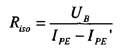
Ein Offsetfehler der Strommessung hat durch die Differenzmessung keinen Einfluß auf den ermittelten Riso-Wert, so dass die Messgenauigkeit wiederum verbessert wird.An offset error of the current measurement has no influence on the determined R iso value by the difference measurement, so that the measurement accuracy is again improved.
In einer bevorzugten dritten Ausgestaltung gemäß Anspruch 4 der Erfindung wird die aufwendige potentialfreie Strommessung an einen der beiden Pole der Anlage verlegt, so dass die Auswertung leichter durch einen Mikroprozessor mit entsprechendem Bezugspotential erfolgen kann (Fig. 5). Dazu wird ein Schalter S2 nicht direkt an einen Pol angeschlossen, sondern über eine Stromquelle, die eine im Verhältnis zur Betriebsspannung UB vernachlässigbare Versorgungsspannung benötigt. Diese wird durch einen entsprechend angesteuerten Transistor, z.B. einen bipolaren Transistor mit möglichst hoher Stromverstärkung oder einen Feldeffekttransistor, zur Verfügung gestellt. Der Kollektor- bzw. Drainanschluss des Transistors wird mit dem nicht mit PE verbundenen Anschluss des zweiten Schalters S1 verbunden. Zwischen diesem Verbindungspunkt und dem zweiten Pol wird eine Strommesseinrichtung angeschlossen. Wenn Iplus der Strom bei geschlossenem Schalter S1 und geöffnetem Schalter S2 und Iplus' der Strom bei geschlossenem Schalter S2 und geöffnetem Schalter S1 ist, ergibt sich 


Wiederum durch die Differenzmessung gehen sowohl Offsetfehler der Strommessung wie auch Streuungen der Stromquelle nicht in die Berechnung ein, so dass auch hier eine hohe Messgenauigkeit erzielt wird. Zur einfachen Auswertung der Messung durch einen Mikrocontroller kann der Strom lplus über einen Shunt geführt werden, der an einen A/D-Wandler im Mikrocontroller angeschlossen ist. Der Mikrocontroller kann dann nacheinander die Messwerte für UB, lplus und lplus aufnehmen und die Berechnung von Riso vornehmen.Again by the difference measurement, both offset errors of the current measurement and also variations of the current source are not included in the calculation, so that here too a high measurement accuracy is achieved. For easy evaluation of the measurement by a microcontroller, the current I plus can be passed through a shunt which is connected to an A / D converter in the microcontroller. The microcontroller can then take successively the readings for U B , L plus and L plus and calculate R iso .
Besonders vorteilhaft stellt sich die Messung des Isolationswiderstandes bei Photovoltaik-Anlagen zur elektrischen Energieerzeugung dar. Durch eine präzise Überwachung auf Erdschlüsse kann eine Gefährdung von Personen oder empfindlichen elektronischen Geräten rechtzeitig erkannt werden, selbst wenn mehrere Isolationsfehler auf unterschiedlichen Potentialen auftreten.The measurement of the insulation resistance in photovoltaic systems for the generation of electrical energy is particularly advantageous. Precise monitoring of ground faults can detect in good time a hazard to persons or sensitive electronic devices, even if several insulation faults occur at different potentials.
Besonders vorteilhaft ist der Einsatz der erfindungsgemäßen Messanordnung bei transformatorlosen Wechselrichtern. Für diese Wechselrichter sind niederohmige Erdschlüsse auch in der Generatormitte eine Gefahr, da hierdurch der Wechselrichterausgang praktisch kurzgeschlossen wird. Die resultierenden hohen Ströme können zur Beschädigung bzw. Zerstörung der Leistungshalbleiter führen. Schäden an den Halbleitern des Wechselrichters können zwar durch andere Sicherheitsmaßnahmen wie Stromüberwachung vermieden werden, die Fehlerursache würde aber nicht angezeigt. Die Suche nach dem Fehler wäre dann langwierig und kostspielig, wenn keine Messung des Isolationswiderstandes erfolgt. Die erfindungsgemäße Isolationswiderstandsmessung kann rechtzeitig den Fehler anzeigen sowie das Zuschalten des Wechselrichters auf das öffentliche Netz verhindern. Durch die Erfindung können insbesondere transformatorlose Wechselrichter zuverlässig geschützt und Ausfallzeiten wirksam verkürzt werden.Particularly advantageous is the use of the measuring arrangement according to the invention in transformerless inverters. For these inverters, low-resistance ground faults are also a danger in the generator center, as this practically short circuits the inverter output. The resulting high currents can lead to damage or destruction of the power semiconductors. Damage to the semiconductors of the inverter Although other safety measures such as current monitoring can be avoided, the cause of the fault would not be displayed. The search for the error would be tedious and costly if no measurement of the insulation resistance takes place. The insulation resistance measurement according to the invention can timely indicate the error and prevent the connection of the inverter to the public grid. In particular, transformerless inverters can be reliably protected and downtimes effectively shortened by the invention.
Weitere vorteilhafte Ausgestaltungen der Erfindung sind den Unteransprüchen zu entnehmen.Further advantageous embodiments of the invention can be found in the dependent claims.
Anhand der Zeichnungen wird die Erfindung nachstehend beispielhaft näher erläutert.
- Fig. 1
- zeigt den Aufbau einer netzgekoppelten Photovoltaik-Anlage mit Isolationsfehlern;
- Fig. 2
- zeigt das Ersatzschaltbild einer Anlage mit einer einfachen Messanordnung zur Bestimmung eines einzelnen Leckwiderstands Rn oder Rp;
- Fig. 3
- zeigt eine Darstellung der Erfindung in einer ersten Ausgestaltung mit Spannungsmessung;
- Fig. 4
- zeigt eine Darstellung der Erfindung in einer zweiten Ausgestaltung mit einer Strommessung;
- Fig. 5
- zeigt eine Darstellung der Erfindung in einer dritten Ausgestaltung mit einer indirekten Strommessung mit Hilfe einer Konstantstromquelle und eines Transistors;
- Fig. 1
- shows the construction of a grid-connected photovoltaic system with insulation faults;
- Fig. 2
- shows the equivalent circuit of a system with a simple measuring arrangement for determining a single leakage resistance R n or R p ;
- Fig. 3
- shows a representation of the invention in a first embodiment with voltage measurement;
- Fig. 4
- shows a representation of the invention in a second embodiment with a current measurement;
- Fig. 5
- shows a representation of the invention in a third embodiment with an indirect current measurement by means of a constant current source and a transistor;
Fig. 1 zeigt eine netzgekoppelte Photovoltaik-Anlage als Beispiel für eine auf Isolationsfehler zu überwachende Anlage. Bestandteile der Anlage sind ein Photovoltaik-Generator 1 aus mehreren Solarzellen 2 und ein Wechselrichter 3, der an ein Wechselspannungsnetz 4, das mit der Erde 5 verbunden ist, angeschlossen ist. Die Anlage besitzt einen Pluspol 6 und einen Minuspol 7. Der Wechselrichter 3 besteht beispielsweise aus einem Pufferkondensator 8, Leistungshalbleitern 9, Speicherdrosseln 10 und einer Vorrichtung zur Netzzuschaltung 11.1 shows a grid-connected photovoltaic system as an example of a system to be monitored for insulation faults. Components of the system are a photovoltaic generator 1 of a plurality of solar cells 2 and an inverter 3, which is connected to an AC voltage network 4, which is connected to the earth 5. The system has a positive pole 6 and a
Weiterhin sind als Beispiele für mögliche Isolationsfehler im Photovoltaik-Generator oder Wechselrichter ein Leckwiderstand Rp 12 zwischen Pluspol 6 und Erde 5, ein Leckwiderstand Rn 13 zwischen Minuspol 7 und Erde 5 sowie ein Leckwiderstand Rx 14 von einem beliebigen Potential nach Erde 5 eingezeichnet. Es gilt: 
Das Vorhandensein der Isolationsfehler führt bei Berührung von Anlagenteilen zu Körperströmen und damit zur Gefährdung von Personen. Beim Zuschalten des Netzes ergibt sich ein Stromfluss durch die gesamte Anlage, was zur Beschädigung bzw. Zerstörung der Bauteile der Anlage führen kann.The presence of insulation faults leads to body currents when touching system components and thus endangering persons. When connecting the network, a current flow through the entire system results, which can lead to damage or destruction of the components of the system.
Ein einzelner Isolationsfehler am Plus- oder Minuspol, d.h. ein einzelner Leckwiderstand Rp oder Rn, kann mit einer einfachen Anordnung nach Fig. 2 bestimmt werden. Dazu sind Hilfswiderstände Raux1 und Raux2 erforderlich. Da Rp bzw. Rn zu einem der bekannten, hochohmigen Widerstände Raux1 und Raux2 parallel liegt, kann mit Hilfe der Spannungsteilerregel der Wert der Parallelschaltung und damit auch der Wert von Rn bzw. Rp ermittelt werden.A single insulation fault at the positive or negative pole, ie a single leakage resistance R p or R n , can be determined with a simple arrangement according to FIG. 2. This requires auxiliary resistors R aux1 and R aux2 . Since Rp or R n is parallel to one of the known, high-resistance resistors R aux1 and R aux2 , the value of the parallel connection and thus also the value of R n or R p can be determined with the aid of the voltage divider rule .
Fig. 3 zeigt eine erste Ausgestaltung der Erfindung. Der gezeigte Aufbau wird auch in der
Fig. 4 zeigt eine zweite Ausgestaltung der Erfindung. Hierbei ist eine Strommesseinrichtung zwischen Erde 5 und dem Verbindungspunkt der beiden Schalter vorgesehen, um den Strom zur Berechnung des Isolationswiderstandes zu messen. Der Messzyklus bleibt gegenüber der Vorschrift zu Fig. 3 unverändert.Fig. 4 shows a second embodiment of the invention. Here, a current measuring device between ground 5 and the connection point of the two switches is provided to measure the current for calculating the insulation resistance. The measuring cycle remains unchanged from the rule for FIG. 3.
Fig. 5 zeigt eine bevorzugte dritte Ausführungsform der Erfindung. Bei dieser erfolgt eine indirekte Strommessung. Die Schaltung nutzt eine zusätzliche Konstantstromquelle, die den konstanten Strom Iconst liefert. Der Schalter S2 wird nicht direkt auf den Pluspol geschaltet, sondern über die Stromquelle. Zusätzlich ist ein MOSFET mit geeigneter Ansteuerung UG den beiden Schaltern S1 und S2 parallel geschaltet. Von Vorteil ist hierbei, dass statt des Stromes IPE mit Bezug zur Erde 5 ein Strom lplus mit Bezug zum Pluspol der Anlage gemessen wird. Der Strom kann so, z.B. über einen Shunt, gut mit einem Mikroprozessor gemessen werden, dessen Bezugspotential auf diesem Pol liegt. Wie auch bei der Ausgestaltung nach Fig. 4 ist bei dieser Lösung eine genaue Messung ohne hochpräzise Widerstände möglich.Fig. 5 shows a preferred third embodiment of the invention. In this case, an indirect current measurement takes place. The circuit uses an additional constant current source, which supplies the constant current I const . The switch S 2 is not switched directly to the positive pole, but via the power source. In addition, a MOSFET with suitable control U G is connected in parallel to the two switches S 1 and S 2 . The advantage here is that instead of the current I PE with respect to the earth 5, a current I plus is measured with respect to the positive pole of the system. The current can thus be measured, for example via a shunt, well with a microprocessor whose reference potential lies on this pole. As with the embodiment according to FIG. 4, an accurate measurement without high-precision resistances is possible with this solution.
Mit dem vorgestellten Verfahren und den beschriebenen Messanordnungen kann also der Isolationswiderstand Riso eines unter Spannung stehenden elektrischen Gerätes oder einer Anlage mit einem Pluspol 6 und einem Minuspol 7 bestimmt werden. Beide Schalter S1, S2 stellen beim Schließen jeweils einen Strompfad zwischen Erde und einem der beiden Pole 6,7 her. Mit dieser Anordnung können Isolationsfehler an beiden Polen 6,7, auf beliebigen Potentialen dazwischen sowie beliebige Kombinationen dieser Fehlerfälle erfasst werden. Der sich insgesamt ergebende Isolationswiderstand kann in einfacher Weise sehr genau ermittelt werden.The insulation resistance R iso of a live electrical device or a system with a plus pole 6 and a
- 11
- Photovoltaik-GeneratorPhotovoltaic Generator
- 22
- Solarzellensolar cells
- 33
- Wechselrichterinverter
- 44
- WechselspannungsnetzAC network
- 55
- Erde (PE)Earth (PE)
- 66
- Pluspolpositive pole
- 77
- Minuspolminuspol
- 88th
- Pufferkondensatorbuffer capacitor
- 99
- LeistungshalbleiterPower semiconductor
- 1010
- SpeicherdrosselPower inductor
- 1111
- Vorrichtung zur NetzzuschaltungDevice for mains connection
- 1212
- Stromquellepower source
- 1313
- Transistortransistor
- Riso R iso
- Isolationswiderstandinsulation resistance
- Rprp
- Leckwiderstand am PluspolLeak resistance at the positive pole
- Rn R n
- Leckwiderstand am MinuspolLeak resistance at the negative pole
- Rx Rx
- Leckwiderstand auf ZwischenpotentialLeak resistance at intermediate potential
- UB U B
- Betriebsspannung der Anlage vom Plus- zum MinuspolOperating voltage of the system from plus to minus pole
- Ux U x
- Ersatzspannung zur Beschreibung der Lage von IsolationsfehlernSpare voltage to describe the location of insulation faults
- U1 U 1
- Spannung zwischen Pluspol und ErdeVoltage between positive pole and earth
- U2 U 2
- Spannung zwischen Erde und MinuspolVoltage between earth and negative pole
- Raux1 R aux1
- erster Hilfswiderstand in einfacher Messschaltungfirst auxiliary resistance in simple measuring circuit
- Raux2 R aux2
- zweiter Hilfswiderstand in einfacher Messschaltungsecond auxiliary resistance in simple measuring circuit
- S1 S 1
- erster Schalterfirst switch
- S2 S 2
- zweiter Schaltersecond switch
Claims (13)
dadurch gekennzeichnet,
dass zur Ermittlung des Isolationswiderstandes zwei aufeinanderfolgende Messungen durchgeführt werden, dass bei der ersten dieser Messungen der erste Schalter (S1) geschlossen ist, während der zweite Schalter (S2) geöffnet ist, und dass bei der zweiten dieser Messungen der erste Schalter (S1) geöffnet ist, während der zweite Schalter (S2) geschlossen ist.Measuring arrangement with a grounding point (5) for determining the insulation resistance (R iso ) of a live electrical device or a system with a supply voltage U B having a positive pole (6) and a negative pole (7), wherein two switches (S 1 , S 2 ) or a corresponding changeover switch are present, each of which produces a current path between one of the two poles and the grounding point (3) in order to determine the total resulting insulation resistance (R iso ) when one or more insulation faults occur with any potential reference.
characterized,
in that for the determination of the insulation resistance two successive measurements are made, that in the first of these measurements the first switch (S 1 ) is closed, while the second switch (S 2 ) is opened, and in the second of these measurements the first switch (S 1 ) is open while the second switch (S 2 ) is closed.
dadurch gekennzeichnet,
dass jeweils in Reihe zu den Schaltern S1, S2 zwei hochohmige Widerstände eingefügt werden, die den gleichen, bekannten Wert RS haben, und dass die bei jeder der beiden Messungen direkt oder indirekt bestimmten Spannungen Pluspol gegen Erde sowie Erde gegen Minuspol zur Berechnung des lsolationswiderstands verwendet werden.Measuring arrangement according to claim 1,
characterized,
that in each case in series with the switches S 1 , S 2, two high-impedance resistors are inserted, which have the same, known value R S , and that in each of the two measurements directly or indirectly determined voltages plus pole to earth and ground against negative pole for calculation the insulation resistance can be used.
dadurch gekennzeichnet,
dass eine Strommesseinrichtung zwischen dem Verbindungspunkt der beiden Schalter (S1, S2) und dem Erdungspunkt eingefügt ist, und dass die bei den beiden Messungen an dieser Stelle gemessenen Ströme zur Berechnung des Isolationswiderstandes (Riso) verwendet werden.Measuring arrangement according to claim 1,
characterized,
that a current measuring device between the connection point of the two switches (S 1, S 2) and the ground point is inserted, and that the measured at this point during the two measurements currents are used for the calculation of the insulation resistance (R iso).
dadurch gekennzeichnet,
dass eine Strommesseinrichtung zwischen dem nicht mit dem Erdungspunkt verbundenen Anschluss einer der beiden Schalter (S1, S2) und einem der beiden Pole eingefügt ist, dass der nicht mit dem Erdungspunkt verbundenen Anschluss des anderen Schalters über eine Konstantstromquelle mit dem anderen der beiden Pole verbunden ist, dass ein Transistor so parallel zu den beiden Schaltern angeordnet ist, dass sein Emitter- bzw. Source-Anschluss an die Stromquelle angeschlossen ist, während sein Kollektor- bzw. Drainanschluss an die Strommesseinrichtung angeschlossen ist, und dass die bei den beiden Messungen mit der Strommesseinrichtung gemessenen Ströme zur Berechnung des Isolationswiderstandes (Riso) verwendet werden.Measuring arrangement according to claim 1,
characterized,
in that a current measuring device is inserted between the connection of one of the two switches (S 1 , S 2 ) and one of the two poles not connected to the grounding point, that connection of the other switch not connected to the grounding point being connected to the other of the two poles via a constant current source is connected, that a transistor is arranged parallel to the two switches, that its emitter or source terminal is connected to the power source, while its collector or drain terminal is connected to the current measuring device, and that in the two measurements currents measured with the current measuring device are used to calculate the insulation resistance (R iso ).
dadurch gekennzeichnet,
dass der Isolationswiderstand Riso aus der Parallelschaltung der beiden Werte Rp=RS*(U2/U2'-1) und Rn=RS*(U1'/U1-1) bestimmt wird, wobei RS der Widerstandswert der durch die Schalter geschlossenen Strompfade ist, U1 und U1' Spannungen vom Pluspol nach Erde sind, U2 und U2' Spannungen von Erde zum Minuspol sind, U1 und U2 bei geschlossenem Schalter S1 und geöffnetem Schalter S2 gemessen werden, und U1' und U2' bei geschlossenem Schalter S2 und geöffnetem Schalter S1 gemessen werden.Measuring arrangement according to claim 2,
characterized,
that the insulation resistance R iso from the parallel connection of the two values R p = R S * (U 2 / U 2 '-1) and R n = R S * (U 1' / U 1 -1) is determined, wherein R S the resistance value of the current paths closed by the switches is, U 1 and U 1 'are voltages from positive pole to ground, U 2 and U 2 ' are voltages from ground to negative pole, U 1 and U 2 with switch S 1 closed and switch S open 2 measured and U 1 'and U 2 ' are measured when switch S 2 is closed and switch S 1 is open.
dadurch gekennzeichnet,
dass der Isolationswiderstand Riso aus Riso=UB/(IPE-IPE') berechnet wird, wobei IPE der mit der Strommesseinrichtung gemessene Strom bei geschlossenem Schalter S1 und geöffnetem Schalter S2 ist und IPE' der mit der Strommesseinrichtung gemessene Strom bei geschlossenem Schalter S2 und geöffnetem Schalter S1 ist.Measuring arrangement according to claim 3,
characterized,
in that the insulation resistance R iso is calculated from R iso = U B / (I PE -I PE '), where I PE is the current measured with the current measuring device with switch S 1 closed and switch S 2 open and I PE ' with the Current measuring device measured current when the switch S 2 and switch S 1 is open.
dadurch gekennzeichnet,
dass der Isolationswiderstand Riso aus Riso=UB/(Iplus-Iplus') berechnet wird, wobei Iplus der mit der Strommesseinrichtung gemessene Strom bei geschlossenem Schalter S1 und geöffnetem Schalter S2 ist und Iplus' der mit der Strommesseinrichtung gemessene Strom bei geschlossenem Schalter S2 und geöffnetem Schalter S1 ist..Measuring arrangement according to claim 4,
characterized,
in that the insulation resistance R iso is calculated from R iso = U B / (I plus -I plus '), where I plus the current measured with the current measuring device is S 2 with the switch S 1 closed and the switch S open, and I plus the Current measuring device measured current when switch S 2 is closed and switch S 1 is open ..
dadurch gekennzeichnet,
dass der Strom IPE bzw. Iplus über einen Shunt gemessen wird.Measuring arrangement according to one of the preceding claims,
characterized,
that the current I PE or I plus is measured via a shunt.
dadurch gekennzeichnet,
dass ein Mikrocontroller oder Mikroprozessor zur Berechnung des Isolationswiderstandes (Riso) vorhanden ist.Measuring arrangement according to one of the preceding claims,
characterized,
that a microcontroller or microprocessor for calculating the insulation resistance (R iso ) is present.
dadurch gekennzeichnet,
dass die Schalter (S1, S2) Relaisschalter oder Halbleiterschalter sind.Measuring arrangement according to one of the preceding claims,
characterized,
that the switches (S 1, S 2) relay switches or semiconductor switches.
Applications Claiming Priority (1)
| Application Number | Priority Date | Filing Date | Title |
|---|---|---|---|
| DE102006022686.0A DE102006022686B4 (en) | 2006-05-16 | 2006-05-16 | Measuring arrangement for determining the insulation resistance of an electrical device or a system |
Publications (2)
| Publication Number | Publication Date |
|---|---|
| EP1857825A1 true EP1857825A1 (en) | 2007-11-21 |
| EP1857825B1 EP1857825B1 (en) | 2019-07-10 |
Family
ID=38371028
Family Applications (1)
| Application Number | Title | Priority Date | Filing Date |
|---|---|---|---|
| EP07008171.6A Active EP1857825B1 (en) | 2006-05-16 | 2007-04-21 | Measuring apparatus |
Country Status (3)
| Country | Link |
|---|---|
| US (2) | US7576547B2 (en) |
| EP (1) | EP1857825B1 (en) |
| DE (1) | DE102006022686B4 (en) |
Cited By (30)
| Publication number | Priority date | Publication date | Assignee | Title |
|---|---|---|---|---|
| EP2157437A1 (en) | 2008-08-19 | 2010-02-24 | SMA Solar Technology AG | Method for measuring a current, particularly through an earthing device |
| EP2333568A1 (en) * | 2009-12-10 | 2011-06-15 | Johnson Controls Saft Advanced Power Solutions LLC | Determination of insulation resistance of an electric DC circuit |
| EP2407996A2 (en) | 2008-03-31 | 2012-01-18 | SMA Solar Technology AG | Current sensing arrangement in an inverter |
| CN102520254A (en) * | 2012-01-06 | 2012-06-27 | 西安龙腾新能源科技发展有限公司 | Detection method of insulation resistance of high-precision photovoltaic inverter |
| WO2012139678A1 (en) * | 2011-04-11 | 2012-10-18 | Phoenix Contact Gmbh & Co Kg | Monitoring device for an isolated network of a photovoltaic system |
| ES2390148A1 (en) * | 2010-12-17 | 2012-11-07 | Zigor Corporacion, S. A. | Measuring the electrical insulation resistance of a DC voltage source |
| WO2012164073A1 (en) * | 2011-06-01 | 2012-12-06 | Commissariat à l'énergie atomique et aux énergies alternatives | Detection of an insulation defect |
| FR2976085A1 (en) * | 2011-06-01 | 2012-12-07 | Commissariat Energie Atomique | DEVICE FOR DETECTING AN ISOLATION FAULT |
| FR2976083A1 (en) * | 2011-06-01 | 2012-12-07 | Commissariat Energie Atomique | Device for detecting insulation fault in e.g. lithium ion phosphate battery of motorization system of electric vehicle, has control circuit for simultaneously maintaining one of two switches in open state and other switch in closed state |
| FR2976084A1 (en) * | 2011-06-01 | 2012-12-07 | Commissariat Energie Atomique | Insulation fault detection device for e.g. lithium ion phosphate battery of motorization system of electric car, has control circuit to simultaneously maintain one of current limiting circuits in open state and other circuit in closed state |
| WO2012171444A1 (en) * | 2011-06-13 | 2012-12-20 | 中兴通讯股份有限公司 | Direct current power supply insulation detection device and detection method therefor |
| CN102967765A (en) * | 2011-09-01 | 2013-03-13 | 阳光电源股份有限公司 | Detection circuit for direct-current power supply insulation against ground and detection method and inverter of detection circuit |
| EP2570289A1 (en) * | 2011-09-16 | 2013-03-20 | Magna E-Car Systems GmbH & Co OG | Device for determining the insulation resistance of a high-voltage battery system |
| FR2988854A1 (en) * | 2012-03-28 | 2013-10-04 | Bosch Gmbh Robert | CIRCUIT AND METHOD FOR MONITORING A POTENTIAL SEPARATION |
| DE102012104752B3 (en) * | 2012-06-01 | 2013-11-28 | Sma Solar Technology Ag | Method for measuring an insulation resistance for an inverter and inverter |
| EP2677330A1 (en) * | 2012-06-22 | 2013-12-25 | Danfoss Drives A/S | Method for determining isolation faults in photovoltaic installations |
| WO2014049247A1 (en) * | 2012-09-28 | 2014-04-03 | Renault S.A.S | Method and device for determining the characteristics of an insulation fault |
| US8717047B2 (en) | 2008-08-19 | 2014-05-06 | Sma Solar Technology Ag | Method for measuring a current, in particular by means of a grounding apparatus |
| CN103944506A (en) * | 2013-12-26 | 2014-07-23 | 中国电子科技集团公司第四十一研究所 | Photovoltaic array grounding impedance detection system and method |
| CN104569607A (en) * | 2014-12-26 | 2015-04-29 | 北京泰兴科技有限公司 | Direct current insulation monitoring method and device |
| EP2502084A4 (en) * | 2009-11-19 | 2015-06-03 | Valence Technology Inc | Battery insulation resistance measurement methods, insulation resistance, measurement methods, insulation resistance determination apparatuses, and aritcles of manufacture |
| CN104749441A (en) * | 2015-03-27 | 2015-07-01 | 华为技术有限公司 | Insulation resistance measurement circuit |
| CN105092971A (en) * | 2014-05-05 | 2015-11-25 | 唐航波 | Pure electric high-voltage insulated resistance real-time online detection method |
| CN106093586A (en) * | 2016-08-17 | 2016-11-09 | 苏州爱康能源工程技术股份有限公司 | Photovoltaic combiner box insulation resistance of DC system detecting system and detection method thereof |
| CN106603007A (en) * | 2016-12-16 | 2017-04-26 | 阳光电源股份有限公司 | Photovoltaic array-to-ground insulation impedance detection circuit |
| DE102015122636A1 (en) | 2015-12-22 | 2017-06-22 | Sma Solar Technology Ag | Inverter with mains separation point and insulation resistance measurement as well as method for measuring an insulation resistance |
| EP2331977A4 (en) * | 2008-09-26 | 2017-07-26 | Volvo Lastvagnar AB | Method for monitoring insulation faults in an electric network and vehicle comprising an insulation fault monitor |
| DE102017113192B3 (en) | 2017-06-14 | 2018-07-12 | Sma Solar Technology Ag | Fail-safe insulation resistance determination in a photovoltaic system |
| CN108445365A (en) * | 2018-04-26 | 2018-08-24 | 湖北三江航天万峰科技发展有限公司 | A kind of insulation impedance automated watch-keeping facility |
| CN112924829A (en) * | 2021-02-26 | 2021-06-08 | 科世达(上海)智能设备有限公司 | Insulation detection device |
Families Citing this family (38)
| Publication number | Priority date | Publication date | Assignee | Title |
|---|---|---|---|---|
| KR101124833B1 (en) * | 2008-03-31 | 2012-03-26 | 에스엠에이 솔라 테크놀로지 아게 | Switching apparatus for grounding an inverter |
| FI122202B (en) * | 2008-12-09 | 2011-10-14 | Waertsilae Finland Oy | Fuel cell device and method for supplying electricity to an electricity grid |
| FI122083B (en) | 2009-01-23 | 2011-08-15 | Waertsilae Finland Oy | Arrangement and method for monitoring electrical insulation of a fuel cell device |
| ES2364900T3 (en) | 2009-03-16 | 2011-09-16 | Sma Solar Technology Ag | PROCEDURE AND DEVICE FOR THE CONTROL OF THE ISOLATION OF AN IT NETWORK. |
| KR101354583B1 (en) * | 2010-09-17 | 2014-01-22 | 에스케이이노베이션 주식회사 | Insulation resistance measurement circuit |
| DE102010055550A1 (en) * | 2010-12-22 | 2012-06-28 | Sma Solar Technology Ag | Inverter, power plant and method of operating a power plant |
| JP2014508939A (en) * | 2011-03-04 | 2014-04-10 | パセコ コーポレイション | Measurement of insulation resistance of solar cell array variable solar panel |
| US20130027049A1 (en) * | 2011-07-28 | 2013-01-31 | Tesla Motors, Inc. | Method for Determining Battery Pack Isolation Resistance Via Dual Bus Monitoring |
| US8168315B1 (en) | 2011-08-23 | 2012-05-01 | Tesla Motors, Inc. | Method for detecting battery thermal events via battery pack isolation monitoring |
| DE102011055220B4 (en) | 2011-11-10 | 2017-02-09 | Sma Solar Technology Ag | Connecting an inverter in a solar power plant with shifted potential center |
| DE102011055371B4 (en) | 2011-11-15 | 2016-10-13 | Sma Solar Technology Ag | Power-limited generator earthing - Circuit arrangement and photovoltaic inverter with circuit arrangement |
| DE102012100193B4 (en) * | 2012-01-11 | 2020-09-10 | Hanwha Q Cells Gmbh | Photovoltaic arrangement comprising a solar system and a solar inverter, and a method for operating such a photovoltaic arrangement |
| DE102012100477C5 (en) * | 2012-01-20 | 2017-11-02 | Sma Solar Technology Ag | Shunt current measurement for multistring devices and interleaving converters |
| PL2700962T3 (en) * | 2012-08-24 | 2019-03-29 | Omicron Electronics Gmbh | Measurement of a resistance of a switch contact of an electrical circuit breaker |
| DE102012222251A1 (en) * | 2012-12-04 | 2014-06-05 | Bender Gmbh & Co. Kg | Insulation monitoring device with measuring circuit separation |
| CN103630745B (en) * | 2013-05-15 | 2017-04-12 | 上海正泰电源系统有限公司 | High-precision multi-path common-grounded direct-current power supply insulation resistance detection circuit and method |
| WO2016049856A1 (en) * | 2014-09-30 | 2016-04-07 | 阳光电源股份有限公司 | Safety detection device and method of grid-connected inverter |
| US10371735B2 (en) | 2015-11-16 | 2019-08-06 | Deere & Company | Method and system for monitoring electrical isolation |
| CN107305224A (en) * | 2016-04-19 | 2017-10-31 | 台达电子企业管理(上海)有限公司 | Insulation resistance detection circuit, detection method and the photovoltaic DC-to-AC converter of photovoltaic DC-to-AC converter |
| CN106645976A (en) * | 2016-09-30 | 2017-05-10 | 阳光电源股份有限公司 | Ground insulation impedance detection circuit for photovoltaic cell panel |
| CN110133374B (en) * | 2018-02-09 | 2020-08-07 | 华为技术有限公司 | Detection circuit and power supply circuit |
| DE202018104044U1 (en) * | 2018-07-13 | 2019-10-15 | Wago Verwaltungsgesellschaft Mbh | Ground wire monitoring |
| CN108983105B (en) * | 2018-07-26 | 2024-03-15 | 浙江慧众智能装备科技有限公司 | Battery insulation detection circuit and control method thereof |
| KR102256096B1 (en) | 2018-08-27 | 2021-05-27 | 주식회사 엘지에너지솔루션 | Apparatus and method for diagnosing insulation state between battery pack and ground, and the battery pack including the apparatus |
| DE102018126235B4 (en) * | 2018-10-22 | 2020-06-04 | Sma Solar Technology Ag | Process for measuring insulation resistance in inverters with multi-point topology and inverters with multi-point topology |
| DE102018219273A1 (en) * | 2018-11-12 | 2020-05-14 | Kaco New Energy Gmbh | Method for operating a photovoltaic (PV) inverter and PV inverter |
| CN110967557B (en) | 2019-02-25 | 2021-06-15 | 宁德时代新能源科技股份有限公司 | Detection circuit and method |
| CN111208350B (en) * | 2020-03-11 | 2022-04-29 | 上海度普新能源科技有限公司 | Insulation detection circuit and energy storage charging equipment |
| EP3879277A1 (en) | 2020-03-11 | 2021-09-15 | FRONIUS INTERNATIONAL GmbH | Method and photovoltaic conversion device for determining the insulation resistance of a photovoltaic device against ground |
| CN112285426B (en) * | 2020-10-29 | 2022-07-12 | 广东电网有限责任公司电力科学研究院 | Grounding resistance testing method and system of tower grounding device and terminal equipment |
| CN112285425B (en) * | 2020-10-29 | 2022-07-19 | 广东电网有限责任公司电力科学研究院 | Grounding resistance calculation method and device of tower grounding device and terminal equipment |
| DE102020129921A1 (en) | 2020-11-12 | 2022-05-12 | Sma Solar Technology Ag | Method for balancing voltages in a DC network and balancing unit for a DC network |
| CN112666399A (en) * | 2020-12-31 | 2021-04-16 | 江苏固德威电源科技股份有限公司 | Method and device for detecting ground insulation impedance of photovoltaic array |
| CN112803891B (en) * | 2021-01-19 | 2022-04-08 | 阳光电源股份有限公司 | Photovoltaic system fault diagnosis method and device |
| US11714111B2 (en) * | 2021-02-12 | 2023-08-01 | Samsung Sdi Co., Ltd. | Isolation measurement monitoring for ASIL applications |
| PL4043891T3 (en) * | 2021-02-12 | 2023-12-11 | Samsung Sdi Co., Ltd. | Isolation measurement monitoring for asil applications |
| DE102021119830B3 (en) | 2021-07-30 | 2022-12-01 | Sensor-Technik Wiedemann Gmbh | Method for self-diagnosis of a circuit for measuring the insulation resistance of a high-voltage system |
| DE102022128496B3 (en) | 2022-10-27 | 2024-02-15 | Gottfried Wilhelm Leibniz Universität Hannover, Körperschaft des öffentlichen Rechts | Circuit arrangement and method for monitoring an insulation resistance and/or a switching capability of an electrical network isolating device |
Citations (8)
| Publication number | Priority date | Publication date | Assignee | Title |
|---|---|---|---|---|
| DE1513510A1 (en) * | 1965-08-12 | 1969-09-11 | Siemens Ag | Circuit arrangement for earth fault monitoring |
| GB1504181A (en) * | 1975-01-09 | 1978-03-15 | Lansing Bagnall Ltd | Detection of earth faults |
| DE3513849A1 (en) | 1985-04-17 | 1986-10-23 | Quante Fernmeldetechnik GmbH, 5600 Wuppertal | Method for monitoring the insulation resistances of a group of modules of an electrical installation with a common earth-free power supply, in particular a telecommunications or signalling device |
| WO1996005516A1 (en) * | 1994-08-17 | 1996-02-22 | Square D Company | System for monitoring a dual voltage ungrounded system |
| EP0833423A2 (en) | 1996-09-11 | 1998-04-01 | Cegelec Controls Ltd. | Apparatus and method for monitoring an earth-leakage state of a power distribution system |
| EP1265076A1 (en) | 2001-06-08 | 2002-12-11 | "VLAAMSE INSTELLING VOOR TECHNOLOGISCH ONDERZOEK", afgekort "V.I.T.O." | Safety device for monitoring a DC bus insulation |
| EP1437600A1 (en) * | 2003-01-09 | 2004-07-14 | DaimlerChrysler AG | Circuit and method for ground fault detection |
| WO2004093284A1 (en) * | 2003-04-15 | 2004-10-28 | Koninklijke Philips Electronics N.V. | Solar power system |
Family Cites Families (6)
| Publication number | Priority date | Publication date | Assignee | Title |
|---|---|---|---|---|
| JPS5765053A (en) * | 1980-10-08 | 1982-04-20 | Hitachi Ltd | Test method for subscriber line |
| ATE56280T1 (en) * | 1986-06-25 | 1990-09-15 | Mania Gmbh | METHOD AND DEVICE FOR ELECTRICAL TESTING OF CIRCUIT BOARDS. |
| JPH0384475A (en) * | 1989-08-28 | 1991-04-10 | Toyo Commun Equip Co Ltd | Measurement of insulation resistance for dc circuit |
| JP2001345472A (en) * | 2000-03-29 | 2001-12-14 | Canon Inc | Method and equipment for inspecting solar cell module, and its manufacturing method, method and equipment for inspecting photovoltaic power generation system, and equipment for measuring insulation resistance and withstand voltage tester |
| JP2001275259A (en) * | 2000-03-29 | 2001-10-05 | Canon Inc | Linked system inverter and distributed power generation system |
| JP2003098215A (en) * | 2001-09-26 | 2003-04-03 | Canon Inc | Earth detection method and device in power conversion system |
-
2006
- 2006-05-16 DE DE102006022686.0A patent/DE102006022686B4/en active Active
-
2007
- 2007-04-21 EP EP07008171.6A patent/EP1857825B1/en active Active
- 2007-05-14 US US11/803,195 patent/US7576547B2/en not_active Ceased
-
2011
- 2011-08-18 US US13/212,859 patent/USRE44455E1/en active Active
Patent Citations (8)
| Publication number | Priority date | Publication date | Assignee | Title |
|---|---|---|---|---|
| DE1513510A1 (en) * | 1965-08-12 | 1969-09-11 | Siemens Ag | Circuit arrangement for earth fault monitoring |
| GB1504181A (en) * | 1975-01-09 | 1978-03-15 | Lansing Bagnall Ltd | Detection of earth faults |
| DE3513849A1 (en) | 1985-04-17 | 1986-10-23 | Quante Fernmeldetechnik GmbH, 5600 Wuppertal | Method for monitoring the insulation resistances of a group of modules of an electrical installation with a common earth-free power supply, in particular a telecommunications or signalling device |
| WO1996005516A1 (en) * | 1994-08-17 | 1996-02-22 | Square D Company | System for monitoring a dual voltage ungrounded system |
| EP0833423A2 (en) | 1996-09-11 | 1998-04-01 | Cegelec Controls Ltd. | Apparatus and method for monitoring an earth-leakage state of a power distribution system |
| EP1265076A1 (en) | 2001-06-08 | 2002-12-11 | "VLAAMSE INSTELLING VOOR TECHNOLOGISCH ONDERZOEK", afgekort "V.I.T.O." | Safety device for monitoring a DC bus insulation |
| EP1437600A1 (en) * | 2003-01-09 | 2004-07-14 | DaimlerChrysler AG | Circuit and method for ground fault detection |
| WO2004093284A1 (en) * | 2003-04-15 | 2004-10-28 | Koninklijke Philips Electronics N.V. | Solar power system |
Cited By (52)
| Publication number | Priority date | Publication date | Assignee | Title |
|---|---|---|---|---|
| EP2407996A2 (en) | 2008-03-31 | 2012-01-18 | SMA Solar Technology AG | Current sensing arrangement in an inverter |
| EP2407996A3 (en) * | 2008-03-31 | 2012-03-28 | SMA Solar Technology AG | Current sensing arrangement in an inverter |
| US8169226B2 (en) | 2008-08-19 | 2012-05-01 | Sma Solar Technology Ag | Method for measuring a current, in particular by means of a grounding apparatus |
| US8717047B2 (en) | 2008-08-19 | 2014-05-06 | Sma Solar Technology Ag | Method for measuring a current, in particular by means of a grounding apparatus |
| EP2157437A1 (en) | 2008-08-19 | 2010-02-24 | SMA Solar Technology AG | Method for measuring a current, particularly through an earthing device |
| EP2331977A4 (en) * | 2008-09-26 | 2017-07-26 | Volvo Lastvagnar AB | Method for monitoring insulation faults in an electric network and vehicle comprising an insulation fault monitor |
| US9581652B2 (en) | 2009-11-19 | 2017-02-28 | Valence Technology, Inc. | Battery insulation resistance measurement methods, insulation resistance measurement methods, insulation resistance determination apparatuses, and articles of manufacture |
| EP2502084A4 (en) * | 2009-11-19 | 2015-06-03 | Valence Technology Inc | Battery insulation resistance measurement methods, insulation resistance, measurement methods, insulation resistance determination apparatuses, and aritcles of manufacture |
| EP2333568A1 (en) * | 2009-12-10 | 2011-06-15 | Johnson Controls Saft Advanced Power Solutions LLC | Determination of insulation resistance of an electric DC circuit |
| US8466691B2 (en) | 2009-12-10 | 2013-06-18 | Johnson Controls-Saft Advanced Power Solutions Llc | Determination of insulation resistance of an electric DC circuit |
| ES2390148A1 (en) * | 2010-12-17 | 2012-11-07 | Zigor Corporacion, S. A. | Measuring the electrical insulation resistance of a DC voltage source |
| WO2012139678A1 (en) * | 2011-04-11 | 2012-10-18 | Phoenix Contact Gmbh & Co Kg | Monitoring device for an isolated network of a photovoltaic system |
| FR2976083A1 (en) * | 2011-06-01 | 2012-12-07 | Commissariat Energie Atomique | Device for detecting insulation fault in e.g. lithium ion phosphate battery of motorization system of electric vehicle, has control circuit for simultaneously maintaining one of two switches in open state and other switch in closed state |
| US9606165B2 (en) | 2011-06-01 | 2017-03-28 | Commissariat A L'energie Atomique Et Aux Energies Alternatives | Device for detecting a defect in insulation |
| WO2012171818A1 (en) * | 2011-06-01 | 2012-12-20 | Commissariat à l'énergie atomique et aux énergies alternatives | Device for detecting a defect in insulation |
| FR2976084A1 (en) * | 2011-06-01 | 2012-12-07 | Commissariat Energie Atomique | Insulation fault detection device for e.g. lithium ion phosphate battery of motorization system of electric car, has control circuit to simultaneously maintain one of current limiting circuits in open state and other circuit in closed state |
| CN103608689A (en) * | 2011-06-01 | 2014-02-26 | 原子能和替代能源委员会 | Detection of an insulation defect |
| FR2976085A1 (en) * | 2011-06-01 | 2012-12-07 | Commissariat Energie Atomique | DEVICE FOR DETECTING AN ISOLATION FAULT |
| WO2012164073A1 (en) * | 2011-06-01 | 2012-12-06 | Commissariat à l'énergie atomique et aux énergies alternatives | Detection of an insulation defect |
| US9322867B2 (en) | 2011-06-01 | 2016-04-26 | Commissariat A L'energie Atomique Et Aux Energies Alternatives | Detection of an insulation defect |
| WO2012171444A1 (en) * | 2011-06-13 | 2012-12-20 | 中兴通讯股份有限公司 | Direct current power supply insulation detection device and detection method therefor |
| CN102967765A (en) * | 2011-09-01 | 2013-03-13 | 阳光电源股份有限公司 | Detection circuit for direct-current power supply insulation against ground and detection method and inverter of detection circuit |
| CN103048545A (en) * | 2011-09-16 | 2013-04-17 | 麦格纳电动汽车系统公司 | Device for determining the insulation resistance of a high-voltage battery system |
| EP2570289A1 (en) * | 2011-09-16 | 2013-03-20 | Magna E-Car Systems GmbH & Co OG | Device for determining the insulation resistance of a high-voltage battery system |
| US9244108B2 (en) | 2011-09-16 | 2016-01-26 | Samsung Sdi Co., Ltd. | Device for detecting the insulation resistance of a high voltage battery system |
| CN103048545B (en) * | 2011-09-16 | 2016-04-20 | 三星Sdi株式会社 | For detecting the device of the insulation resistance of high voltage battery system |
| CN102520254A (en) * | 2012-01-06 | 2012-06-27 | 西安龙腾新能源科技发展有限公司 | Detection method of insulation resistance of high-precision photovoltaic inverter |
| FR2988854A1 (en) * | 2012-03-28 | 2013-10-04 | Bosch Gmbh Robert | CIRCUIT AND METHOD FOR MONITORING A POTENTIAL SEPARATION |
| WO2013178654A1 (en) | 2012-06-01 | 2013-12-05 | Sma Solar Technology Ag | Insulation resistance measurement for inverters |
| US9797853B2 (en) | 2012-06-01 | 2017-10-24 | Sma Solar Technology Ag | Insulation resistance measurement for inverters |
| DE102012104752B3 (en) * | 2012-06-01 | 2013-11-28 | Sma Solar Technology Ag | Method for measuring an insulation resistance for an inverter and inverter |
| EP2677330A1 (en) * | 2012-06-22 | 2013-12-25 | Danfoss Drives A/S | Method for determining isolation faults in photovoltaic installations |
| WO2014049247A1 (en) * | 2012-09-28 | 2014-04-03 | Renault S.A.S | Method and device for determining the characteristics of an insulation fault |
| FR2996311A1 (en) * | 2012-09-28 | 2014-04-04 | Renault Sa | METHOD AND DEVICE FOR DETERMINING THE CHARACTERISTICS OF AN ISOLATION FAULT |
| CN103944506A (en) * | 2013-12-26 | 2014-07-23 | 中国电子科技集团公司第四十一研究所 | Photovoltaic array grounding impedance detection system and method |
| CN103944506B (en) * | 2013-12-26 | 2017-01-04 | 中国电子科技集团公司第四十一研究所 | The detecting system of a kind of photovoltaic array impedance ground and method |
| CN105092971A (en) * | 2014-05-05 | 2015-11-25 | 唐航波 | Pure electric high-voltage insulated resistance real-time online detection method |
| CN104569607A (en) * | 2014-12-26 | 2015-04-29 | 北京泰兴科技有限公司 | Direct current insulation monitoring method and device |
| CN104749441B (en) * | 2015-03-27 | 2018-11-16 | 华为技术有限公司 | A kind of insulation resistance measurement circuit |
| CN104749441A (en) * | 2015-03-27 | 2015-07-01 | 华为技术有限公司 | Insulation resistance measurement circuit |
| WO2017108633A1 (en) * | 2015-12-22 | 2017-06-29 | Sma Solar Technology Ag | Inverter having network separation point and insulation resistance measurement, and method for measuring an insulation resistance |
| DE102015122636B4 (en) * | 2015-12-22 | 2017-07-13 | Sma Solar Technology Ag | Inverter with mains separation point and insulation resistance measurement as well as method for measuring an insulation resistance |
| DE102015122636A1 (en) | 2015-12-22 | 2017-06-22 | Sma Solar Technology Ag | Inverter with mains separation point and insulation resistance measurement as well as method for measuring an insulation resistance |
| CN106093586A (en) * | 2016-08-17 | 2016-11-09 | 苏州爱康能源工程技术股份有限公司 | Photovoltaic combiner box insulation resistance of DC system detecting system and detection method thereof |
| CN106093586B (en) * | 2016-08-17 | 2022-10-11 | 苏州爱康能源集团股份有限公司 | Insulation resistance detection system and detection method for photovoltaic combiner box direct current system |
| CN106603007A (en) * | 2016-12-16 | 2017-04-26 | 阳光电源股份有限公司 | Photovoltaic array-to-ground insulation impedance detection circuit |
| CN106603007B (en) * | 2016-12-16 | 2018-09-28 | 阳光电源股份有限公司 | Photovoltaic array ground insulation impedance detection circuit |
| WO2018228730A1 (en) | 2017-06-14 | 2018-12-20 | Sma Solar Technology Ag | Single-fault-tolerant isolation resistance determination in a photovoltaic system |
| DE102017113192B3 (en) | 2017-06-14 | 2018-07-12 | Sma Solar Technology Ag | Fail-safe insulation resistance determination in a photovoltaic system |
| CN108445365A (en) * | 2018-04-26 | 2018-08-24 | 湖北三江航天万峰科技发展有限公司 | A kind of insulation impedance automated watch-keeping facility |
| CN108445365B (en) * | 2018-04-26 | 2020-08-11 | 湖北三江航天万峰科技发展有限公司 | Automatic insulation impedance monitoring device |
| CN112924829A (en) * | 2021-02-26 | 2021-06-08 | 科世达(上海)智能设备有限公司 | Insulation detection device |
Also Published As
| Publication number | Publication date |
|---|---|
| US7576547B2 (en) | 2009-08-18 |
| DE102006022686A1 (en) | 2007-11-22 |
| USRE44455E1 (en) | 2013-08-27 |
| US20070285102A1 (en) | 2007-12-13 |
| EP1857825B1 (en) | 2019-07-10 |
| DE102006022686B4 (en) | 2018-03-15 |
Similar Documents
| Publication | Publication Date | Title |
|---|---|---|
| EP1857825B1 (en) | Measuring apparatus | |
| DE102012104752B3 (en) | Method for measuring an insulation resistance for an inverter and inverter | |
| AT517620B1 (en) | Method and test device for testing a wiring of transducers | |
| EP0642027A1 (en) | Method and device for detecting earth faults of the conductors in a electrical machine | |
| WO2011029464A1 (en) | Fault detection in energy supply networks having an unearthed or resonant-earthed star point | |
| EP3259820B1 (en) | Apparatus for determining insulation resistance at a pv generator, and photovoltaic installation | |
| EP1304580A2 (en) | Method for calculating the fault point distance to a single-pole earth fault within an electric power network | |
| EP3631976B1 (en) | Method for detecting a contact fault in a photovoltaic system | |
| DE102018126028B4 (en) | Fault detection circuit and method for detecting a neutral point ground fault | |
| DE102018121979A1 (en) | Insulation monitoring method for an inverter-fed power supply system | |
| DE102010036847B4 (en) | Method and device for external current detection | |
| EP3451477B1 (en) | Detection of a fault in a dc transmission system | |
| DE19545267C2 (en) | Method for obtaining faulty loops in signals characterizing a multi-phase electrical power supply network | |
| DE102013018294B4 (en) | Device and method for recording the electrical energy of single or multi-phase electrical consumers | |
| DE102013202868C5 (en) | Fault and / or load detection device for a low or high voltage system | |
| EP2171488A1 (en) | Method for locating a ground fault according to the distance protection principle and electric distance protection device | |
| EP4252014B1 (en) | Monitoring device for network replacement operation | |
| DE102021112016B3 (en) | Method and device for determining a ground fault direction | |
| EP3896463B1 (en) | Method and device for monitoring the disconnection of a power generator | |
| EP1001270B1 (en) | Method for testing a ground connection | |
| DE102018113627B4 (en) | Method and device for fault diagnosis in an electrical network having a ring structure, and computer program product | |
| DE102013002018B4 (en) | Method for monitoring the insulation of a circuit arrangement | |
| EP2653879B1 (en) | Device for the simultaneous output of a direct voltage signal with a non-linear power-voltage curve | |
| AT516121A1 (en) | Checking a multi-pole electrical circuit breaker | |
| DE3921063C1 (en) | Detecting short to earth in non-earthed three=phase power supply - measuring and evaluating direct currents derived from voltages tapped from resistors assigned to each lead |
Legal Events
| Date | Code | Title | Description |
|---|---|---|---|
| PUAI | Public reference made under article 153(3) epc to a published international application that has entered the european phase |
Free format text: ORIGINAL CODE: 0009012 |
|
| AK | Designated contracting states |
Kind code of ref document: A1 Designated state(s): AT BE BG CH CY CZ DE DK EE ES FI FR GB GR HU IE IS IT LI LT LU LV MC MT NL PL PT RO SE SI SK TR |
|
| AX | Request for extension of the european patent |
Extension state: AL BA HR MK YU |
|
| 17P | Request for examination filed |
Effective date: 20071023 |
|
| 17Q | First examination report despatched |
Effective date: 20071228 |
|
| RAP1 | Party data changed (applicant data changed or rights of an application transferred) |
Owner name: SMA SOLAR TECHNOLOGY AG |
|
| AKX | Designation fees paid |
Designated state(s): AT BE BG CH CY CZ DE DK EE ES FI FR GB GR HU IE IS IT LI LT LU LV MC MT NL PL PT RO SE SI SK TR |
|
| STAA | Information on the status of an ep patent application or granted ep patent |
Free format text: STATUS: EXAMINATION IS IN PROGRESS |
|
| GRAP | Despatch of communication of intention to grant a patent |
Free format text: ORIGINAL CODE: EPIDOSNIGR1 |
|
| STAA | Information on the status of an ep patent application or granted ep patent |
Free format text: STATUS: GRANT OF PATENT IS INTENDED |
|
| INTG | Intention to grant announced |
Effective date: 20190211 |
|
| GRAJ | Information related to disapproval of communication of intention to grant by the applicant or resumption of examination proceedings by the epo deleted |
Free format text: ORIGINAL CODE: EPIDOSDIGR1 |
|
| STAA | Information on the status of an ep patent application or granted ep patent |
Free format text: STATUS: EXAMINATION IS IN PROGRESS |
|
| GRAR | Information related to intention to grant a patent recorded |
Free format text: ORIGINAL CODE: EPIDOSNIGR71 |
|
| GRAS | Grant fee paid |
Free format text: ORIGINAL CODE: EPIDOSNIGR3 |
|
| STAA | Information on the status of an ep patent application or granted ep patent |
Free format text: STATUS: GRANT OF PATENT IS INTENDED |
|
| GRAA | (expected) grant |
Free format text: ORIGINAL CODE: 0009210 |
|
| STAA | Information on the status of an ep patent application or granted ep patent |
Free format text: STATUS: THE PATENT HAS BEEN GRANTED |
|
| INTC | Intention to grant announced (deleted) | ||
| AK | Designated contracting states |
Kind code of ref document: B1 Designated state(s): AT BE BG CH CY CZ DE DK EE ES FI FR GB GR HU IE IS IT LI LT LU LV MC MT NL PL PT RO SE SI SK TR |
|
| INTG | Intention to grant announced |
Effective date: 20190603 |
|
| REG | Reference to a national code |
Ref country code: GB Ref legal event code: FG4D Free format text: NOT ENGLISH |
|
| REG | Reference to a national code |
Ref country code: CH Ref legal event code: EP Ref country code: AT Ref legal event code: REF Ref document number: 1154139 Country of ref document: AT Kind code of ref document: T Effective date: 20190715 |
|
| REG | Reference to a national code |
Ref country code: DE Ref legal event code: R096 Ref document number: 502007016719 Country of ref document: DE |
|
| REG | Reference to a national code |
Ref country code: IE Ref legal event code: FG4D Free format text: LANGUAGE OF EP DOCUMENT: GERMAN |
|
| REG | Reference to a national code |
Ref country code: NL Ref legal event code: FP |
|
| REG | Reference to a national code |
Ref country code: LT Ref legal event code: MG4D |
|
| PG25 | Lapsed in a contracting state [announced via postgrant information from national office to epo] |
Ref country code: FI Free format text: LAPSE BECAUSE OF FAILURE TO SUBMIT A TRANSLATION OF THE DESCRIPTION OR TO PAY THE FEE WITHIN THE PRESCRIBED TIME-LIMIT Effective date: 20190710 Ref country code: LT Free format text: LAPSE BECAUSE OF FAILURE TO SUBMIT A TRANSLATION OF THE DESCRIPTION OR TO PAY THE FEE WITHIN THE PRESCRIBED TIME-LIMIT Effective date: 20190710 Ref country code: BG Free format text: LAPSE BECAUSE OF FAILURE TO SUBMIT A TRANSLATION OF THE DESCRIPTION OR TO PAY THE FEE WITHIN THE PRESCRIBED TIME-LIMIT Effective date: 20191010 Ref country code: PT Free format text: LAPSE BECAUSE OF FAILURE TO SUBMIT A TRANSLATION OF THE DESCRIPTION OR TO PAY THE FEE WITHIN THE PRESCRIBED TIME-LIMIT Effective date: 20191111 Ref country code: SE Free format text: LAPSE BECAUSE OF FAILURE TO SUBMIT A TRANSLATION OF THE DESCRIPTION OR TO PAY THE FEE WITHIN THE PRESCRIBED TIME-LIMIT Effective date: 20190710 |
|
| PG25 | Lapsed in a contracting state [announced via postgrant information from national office to epo] |
Ref country code: GR Free format text: LAPSE BECAUSE OF FAILURE TO SUBMIT A TRANSLATION OF THE DESCRIPTION OR TO PAY THE FEE WITHIN THE PRESCRIBED TIME-LIMIT Effective date: 20191011 Ref country code: ES Free format text: LAPSE BECAUSE OF FAILURE TO SUBMIT A TRANSLATION OF THE DESCRIPTION OR TO PAY THE FEE WITHIN THE PRESCRIBED TIME-LIMIT Effective date: 20190710 Ref country code: IS Free format text: LAPSE BECAUSE OF FAILURE TO SUBMIT A TRANSLATION OF THE DESCRIPTION OR TO PAY THE FEE WITHIN THE PRESCRIBED TIME-LIMIT Effective date: 20191110 Ref country code: LV Free format text: LAPSE BECAUSE OF FAILURE TO SUBMIT A TRANSLATION OF THE DESCRIPTION OR TO PAY THE FEE WITHIN THE PRESCRIBED TIME-LIMIT Effective date: 20190710 |
|
| PG25 | Lapsed in a contracting state [announced via postgrant information from national office to epo] |
Ref country code: TR Free format text: LAPSE BECAUSE OF FAILURE TO SUBMIT A TRANSLATION OF THE DESCRIPTION OR TO PAY THE FEE WITHIN THE PRESCRIBED TIME-LIMIT Effective date: 20190710 |
|
| PG25 | Lapsed in a contracting state [announced via postgrant information from national office to epo] |
Ref country code: DK Free format text: LAPSE BECAUSE OF FAILURE TO SUBMIT A TRANSLATION OF THE DESCRIPTION OR TO PAY THE FEE WITHIN THE PRESCRIBED TIME-LIMIT Effective date: 20190710 Ref country code: RO Free format text: LAPSE BECAUSE OF FAILURE TO SUBMIT A TRANSLATION OF THE DESCRIPTION OR TO PAY THE FEE WITHIN THE PRESCRIBED TIME-LIMIT Effective date: 20190710 Ref country code: EE Free format text: LAPSE BECAUSE OF FAILURE TO SUBMIT A TRANSLATION OF THE DESCRIPTION OR TO PAY THE FEE WITHIN THE PRESCRIBED TIME-LIMIT Effective date: 20190710 Ref country code: PL Free format text: LAPSE BECAUSE OF FAILURE TO SUBMIT A TRANSLATION OF THE DESCRIPTION OR TO PAY THE FEE WITHIN THE PRESCRIBED TIME-LIMIT Effective date: 20190710 |
|
| PG25 | Lapsed in a contracting state [announced via postgrant information from national office to epo] |
Ref country code: SK Free format text: LAPSE BECAUSE OF FAILURE TO SUBMIT A TRANSLATION OF THE DESCRIPTION OR TO PAY THE FEE WITHIN THE PRESCRIBED TIME-LIMIT Effective date: 20190710 Ref country code: IS Free format text: LAPSE BECAUSE OF FAILURE TO SUBMIT A TRANSLATION OF THE DESCRIPTION OR TO PAY THE FEE WITHIN THE PRESCRIBED TIME-LIMIT Effective date: 20200224 Ref country code: CZ Free format text: LAPSE BECAUSE OF FAILURE TO SUBMIT A TRANSLATION OF THE DESCRIPTION OR TO PAY THE FEE WITHIN THE PRESCRIBED TIME-LIMIT Effective date: 20190710 |
|
| REG | Reference to a national code |
Ref country code: DE Ref legal event code: R097 Ref document number: 502007016719 Country of ref document: DE |
|
| PLBE | No opposition filed within time limit |
Free format text: ORIGINAL CODE: 0009261 |
|
| STAA | Information on the status of an ep patent application or granted ep patent |
Free format text: STATUS: NO OPPOSITION FILED WITHIN TIME LIMIT |
|
| PG2D | Information on lapse in contracting state deleted |
Ref country code: IS |
|
| 26N | No opposition filed |
Effective date: 20200603 |
|
| PG25 | Lapsed in a contracting state [announced via postgrant information from national office to epo] |
Ref country code: SI Free format text: LAPSE BECAUSE OF FAILURE TO SUBMIT A TRANSLATION OF THE DESCRIPTION OR TO PAY THE FEE WITHIN THE PRESCRIBED TIME-LIMIT Effective date: 20190710 |
|
| PG25 | Lapsed in a contracting state [announced via postgrant information from national office to epo] |
Ref country code: MC Free format text: LAPSE BECAUSE OF FAILURE TO SUBMIT A TRANSLATION OF THE DESCRIPTION OR TO PAY THE FEE WITHIN THE PRESCRIBED TIME-LIMIT Effective date: 20190710 |
|
| REG | Reference to a national code |
Ref country code: CH Ref legal event code: PL |
|
| PG25 | Lapsed in a contracting state [announced via postgrant information from national office to epo] |
Ref country code: LU Free format text: LAPSE BECAUSE OF NON-PAYMENT OF DUE FEES Effective date: 20200421 Ref country code: LI Free format text: LAPSE BECAUSE OF NON-PAYMENT OF DUE FEES Effective date: 20200430 Ref country code: CH Free format text: LAPSE BECAUSE OF NON-PAYMENT OF DUE FEES Effective date: 20200430 |
|
| PG25 | Lapsed in a contracting state [announced via postgrant information from national office to epo] |
Ref country code: IE Free format text: LAPSE BECAUSE OF NON-PAYMENT OF DUE FEES Effective date: 20200421 |
|
| REG | Reference to a national code |
Ref country code: AT Ref legal event code: MM01 Ref document number: 1154139 Country of ref document: AT Kind code of ref document: T Effective date: 20200421 |
|
| PG25 | Lapsed in a contracting state [announced via postgrant information from national office to epo] |
Ref country code: AT Free format text: LAPSE BECAUSE OF NON-PAYMENT OF DUE FEES Effective date: 20200421 |
|
| PG25 | Lapsed in a contracting state [announced via postgrant information from national office to epo] |
Ref country code: MT Free format text: LAPSE BECAUSE OF FAILURE TO SUBMIT A TRANSLATION OF THE DESCRIPTION OR TO PAY THE FEE WITHIN THE PRESCRIBED TIME-LIMIT Effective date: 20190710 Ref country code: CY Free format text: LAPSE BECAUSE OF FAILURE TO SUBMIT A TRANSLATION OF THE DESCRIPTION OR TO PAY THE FEE WITHIN THE PRESCRIBED TIME-LIMIT Effective date: 20190710 |
|
| P01 | Opt-out of the competence of the unified patent court (upc) registered |
Effective date: 20230614 |
|
| PGFP | Annual fee paid to national office [announced via postgrant information from national office to epo] |
Ref country code: IT Payment date: 20230428 Year of fee payment: 17 Ref country code: FR Payment date: 20230417 Year of fee payment: 17 Ref country code: DE Payment date: 20230418 Year of fee payment: 17 |
|
| PGFP | Annual fee paid to national office [announced via postgrant information from national office to epo] |
Ref country code: BE Payment date: 20230417 Year of fee payment: 17 |
|
| PGFP | Annual fee paid to national office [announced via postgrant information from national office to epo] |
Ref country code: GB Payment date: 20230420 Year of fee payment: 17 |
|
| PGFP | Annual fee paid to national office [announced via postgrant information from national office to epo] |
Ref country code: NL Payment date: 20240422 Year of fee payment: 18 |