EP1857363A1 - Temperature regulating device - Google Patents
Temperature regulating device Download PDFInfo
- Publication number
- EP1857363A1 EP1857363A1 EP06114251A EP06114251A EP1857363A1 EP 1857363 A1 EP1857363 A1 EP 1857363A1 EP 06114251 A EP06114251 A EP 06114251A EP 06114251 A EP06114251 A EP 06114251A EP 1857363 A1 EP1857363 A1 EP 1857363A1
- Authority
- EP
- European Patent Office
- Prior art keywords
- air
- hot
- cold
- fan
- supplying conditioned
- Prior art date
- Legal status (The legal status is an assumption and is not a legal conclusion. Google has not performed a legal analysis and makes no representation as to the accuracy of the status listed.)
- Withdrawn
Links
- 230000001105 regulatory effect Effects 0.000 title claims abstract description 7
- 238000001816 cooling Methods 0.000 claims description 25
- 230000001143 conditioned effect Effects 0.000 claims description 12
- 238000010438 heat treatment Methods 0.000 claims description 10
- 238000012423 maintenance Methods 0.000 claims description 10
- 238000009826 distribution Methods 0.000 claims description 9
- 238000005057 refrigeration Methods 0.000 claims description 9
- 238000009423 ventilation Methods 0.000 claims description 9
- 230000006978 adaptation Effects 0.000 claims description 6
- 238000011084 recovery Methods 0.000 claims description 6
- 230000002829 reductive effect Effects 0.000 claims description 6
- 238000009413 insulation Methods 0.000 claims description 5
- 230000001276 controlling effect Effects 0.000 claims description 4
- 239000000446 fuel Substances 0.000 claims description 4
- 238000007789 sealing Methods 0.000 claims description 4
- 238000013461 design Methods 0.000 claims description 3
- 239000002828 fuel tank Substances 0.000 claims description 3
- 238000004590 computer program Methods 0.000 claims description 2
- 230000001976 improved effect Effects 0.000 claims description 2
- 230000008595 infiltration Effects 0.000 claims description 2
- 238000001764 infiltration Methods 0.000 claims description 2
- 230000003405 preventing effect Effects 0.000 claims description 2
- 238000003860 storage Methods 0.000 claims description 2
- 238000009421 internal insulation Methods 0.000 claims 1
- 230000001737 promoting effect Effects 0.000 claims 1
- XLYOFNOQVPJJNP-UHFFFAOYSA-N water Substances O XLYOFNOQVPJJNP-UHFFFAOYSA-N 0.000 claims 1
- 238000000034 method Methods 0.000 abstract description 16
- 239000003507 refrigerant Substances 0.000 abstract description 13
- 239000000523 sample Substances 0.000 abstract description 5
- 230000003750 conditioning effect Effects 0.000 abstract 1
- 230000008569 process Effects 0.000 description 14
- 230000000694 effects Effects 0.000 description 5
- 239000007788 liquid Substances 0.000 description 5
- 238000001704 evaporation Methods 0.000 description 4
- 230000008020 evaporation Effects 0.000 description 4
- 238000012986 modification Methods 0.000 description 4
- 230000033228 biological regulation Effects 0.000 description 3
- 230000015572 biosynthetic process Effects 0.000 description 3
- 238000010276 construction Methods 0.000 description 3
- 235000021183 entrée Nutrition 0.000 description 3
- 238000002955 isolation Methods 0.000 description 3
- 230000000670 limiting effect Effects 0.000 description 3
- 230000004048 modification Effects 0.000 description 3
- 240000008042 Zea mays Species 0.000 description 2
- 230000008859 change Effects 0.000 description 2
- 238000005253 cladding Methods 0.000 description 2
- 238000009833 condensation Methods 0.000 description 2
- 230000005494 condensation Effects 0.000 description 2
- 238000012937 correction Methods 0.000 description 2
- 230000006378 damage Effects 0.000 description 2
- 238000009792 diffusion process Methods 0.000 description 2
- 230000001965 increasing effect Effects 0.000 description 2
- 239000000463 material Substances 0.000 description 2
- 210000000056 organ Anatomy 0.000 description 2
- 238000003303 reheating Methods 0.000 description 2
- 230000009183 running Effects 0.000 description 2
- 241000196324 Embryophyta Species 0.000 description 1
- 241000946381 Timon Species 0.000 description 1
- 238000003915 air pollution Methods 0.000 description 1
- 230000003416 augmentation Effects 0.000 description 1
- 239000000428 dust Substances 0.000 description 1
- 238000005485 electric heating Methods 0.000 description 1
- 239000012530 fluid Substances 0.000 description 1
- 230000004907 flux Effects 0.000 description 1
- 238000009434 installation Methods 0.000 description 1
- 238000004519 manufacturing process Methods 0.000 description 1
- 239000003607 modifier Substances 0.000 description 1
- 230000036961 partial effect Effects 0.000 description 1
- 230000009467 reduction Effects 0.000 description 1
- 230000003584 silencer Effects 0.000 description 1
- 238000013456 study Methods 0.000 description 1
- 238000010257 thawing Methods 0.000 description 1
- 238000012546 transfer Methods 0.000 description 1
Images


Classifications
-
- F—MECHANICAL ENGINEERING; LIGHTING; HEATING; WEAPONS; BLASTING
- F25—REFRIGERATION OR COOLING; COMBINED HEATING AND REFRIGERATION SYSTEMS; HEAT PUMP SYSTEMS; MANUFACTURE OR STORAGE OF ICE; LIQUEFACTION SOLIDIFICATION OF GASES
- F25D—REFRIGERATORS; COLD ROOMS; ICE-BOXES; COOLING OR FREEZING APPARATUS NOT OTHERWISE PROVIDED FOR
- F25D17/00—Arrangements for circulating cooling fluids; Arrangements for circulating gas, e.g. air, within refrigerated spaces
- F25D17/04—Arrangements for circulating cooling fluids; Arrangements for circulating gas, e.g. air, within refrigerated spaces for circulating air, e.g. by convection
- F25D17/06—Arrangements for circulating cooling fluids; Arrangements for circulating gas, e.g. air, within refrigerated spaces for circulating air, e.g. by convection by forced circulation
-
- B—PERFORMING OPERATIONS; TRANSPORTING
- B64—AIRCRAFT; AVIATION; COSMONAUTICS
- B64F—GROUND OR AIRCRAFT-CARRIER-DECK INSTALLATIONS SPECIALLY ADAPTED FOR USE IN CONNECTION WITH AIRCRAFT; DESIGNING, MANUFACTURING, ASSEMBLING, CLEANING, MAINTAINING OR REPAIRING AIRCRAFT, NOT OTHERWISE PROVIDED FOR; HANDLING, TRANSPORTING, TESTING OR INSPECTING AIRCRAFT COMPONENTS, NOT OTHERWISE PROVIDED FOR
- B64F1/00—Ground or aircraft-carrier-deck installations
- B64F1/36—Other airport installations
- B64F1/362—Installations for supplying conditioned air to parked aircraft
- B64F1/364—Mobile units
-
- F—MECHANICAL ENGINEERING; LIGHTING; HEATING; WEAPONS; BLASTING
- F24—HEATING; RANGES; VENTILATING
- F24F—AIR-CONDITIONING; AIR-HUMIDIFICATION; VENTILATION; USE OF AIR CURRENTS FOR SCREENING
- F24F1/00—Room units for air-conditioning, e.g. separate or self-contained units or units receiving primary air from a central station
- F24F1/02—Self-contained room units for air-conditioning, i.e. with all apparatus for treatment installed in a common casing
- F24F1/022—Self-contained room units for air-conditioning, i.e. with all apparatus for treatment installed in a common casing comprising a compressor cycle
-
- F—MECHANICAL ENGINEERING; LIGHTING; HEATING; WEAPONS; BLASTING
- F24—HEATING; RANGES; VENTILATING
- F24F—AIR-CONDITIONING; AIR-HUMIDIFICATION; VENTILATION; USE OF AIR CURRENTS FOR SCREENING
- F24F1/00—Room units for air-conditioning, e.g. separate or self-contained units or units receiving primary air from a central station
- F24F1/02—Self-contained room units for air-conditioning, i.e. with all apparatus for treatment installed in a common casing
- F24F1/04—Arrangements for portability
-
- F—MECHANICAL ENGINEERING; LIGHTING; HEATING; WEAPONS; BLASTING
- F25—REFRIGERATION OR COOLING; COMBINED HEATING AND REFRIGERATION SYSTEMS; HEAT PUMP SYSTEMS; MANUFACTURE OR STORAGE OF ICE; LIQUEFACTION SOLIDIFICATION OF GASES
- F25B—REFRIGERATION MACHINES, PLANTS OR SYSTEMS; COMBINED HEATING AND REFRIGERATION SYSTEMS; HEAT PUMP SYSTEMS
- F25B29/00—Combined heating and refrigeration systems, e.g. operating alternately or simultaneously
- F25B29/003—Combined heating and refrigeration systems, e.g. operating alternately or simultaneously of the compression type system
-
- F—MECHANICAL ENGINEERING; LIGHTING; HEATING; WEAPONS; BLASTING
- F25—REFRIGERATION OR COOLING; COMBINED HEATING AND REFRIGERATION SYSTEMS; HEAT PUMP SYSTEMS; MANUFACTURE OR STORAGE OF ICE; LIQUEFACTION SOLIDIFICATION OF GASES
- F25B—REFRIGERATION MACHINES, PLANTS OR SYSTEMS; COMBINED HEATING AND REFRIGERATION SYSTEMS; HEAT PUMP SYSTEMS
- F25B49/00—Arrangement or mounting of control or safety devices
- F25B49/02—Arrangement or mounting of control or safety devices for compression type machines, plants or systems
-
- F—MECHANICAL ENGINEERING; LIGHTING; HEATING; WEAPONS; BLASTING
- F25—REFRIGERATION OR COOLING; COMBINED HEATING AND REFRIGERATION SYSTEMS; HEAT PUMP SYSTEMS; MANUFACTURE OR STORAGE OF ICE; LIQUEFACTION SOLIDIFICATION OF GASES
- F25D—REFRIGERATORS; COLD ROOMS; ICE-BOXES; COOLING OR FREEZING APPARATUS NOT OTHERWISE PROVIDED FOR
- F25D21/00—Defrosting; Preventing frosting; Removing condensed or defrost water
- F25D21/04—Preventing the formation of frost or condensate
Definitions
- the invention relates to a control device for supplying conditioned air (hot and cold air) to various spaces, such as parked aircraft.
- the purpose of the device is the supply of air to users (machines, premises, ...) with piping characteristics (flow / pressure curve) different fixed or variable over time.
- the self-adaptability of the device allows in all circumstances the distribution of an optimal air flow to the instantaneous situation observed.
- Each speaker (user) is characterized by a flow / pressure curve of its own.
- This characteristic can be fixed or evolve over time.
- the fan curve In order to achieve rapid adaptation, the fan curve must evolve rapidly. This will be equipped with a frequency converter. The latter will be controlled by a differential pressure sensor controlling the pressure inside.
- the pressure is controlled at the box housing the battery (evaporator) charged with cooling the air.
- FIG. 1 The implementation of this concept is illustrated in Figure 1 in the appendix, showing pressure curves as a function of the air flow (illustrating the case of fixed speed fans, involving a balance in A1, B1 and C1, and the variant with variable speed as a function of a value P max , involving an equilibrium at A2, B2 and C2).
- Operation with initially selected speeds is restrictive when the user's characteristic changes over time.
- the pressure-maintaining system allows the system to self-adapt by giving the maximum permissible flow rate at any time.
- the pulse temperature should be higher than 0 ° C to prevent frost formation on the connecting pieces or the air distribution system of the user to which the group is connected. Similarly, the temperature can not exceed certain high limits beyond which the integrity of the materials would be reached.
- Oversized equipment can lead to improper operation with too low pulse temperature and too short start / stop cycles of the refrigeration equipment that can degrade the machine.
- equipment throughput will vary not only from one application to another but also over time. This variation will lead to a change in the refrigeration load accentuated by the changing external conditions (temperature and humidity).
- the refrigeration equipment must therefore cope with these modifications and adapt quickly to allow a suitable air supply temperature and a correct automatic adjustment of its refrigerant flow.
- Each circuit of the battery is powered by a regulator whose adjustment is done electronically to allow the adaptation of the flow of refrigerant to the load required by the user.
- the controller determines the degree of opening of each regulator.
- the refrigeration compressor must regulate its capacity quickly (in order to adapt it to that of the need).
- the compressor selected is of the screw type. Capacity control is performed using a low pressure sensor and a capacity drawer between the two compressor screws. The whole is controlled by an automaton.
- the condenser of the refrigerating plant is of the air type. Its regulation allows maintenance at high pressure (condensing pressure) within acceptable limits. However, if the high limit of the condensing pressure stops the machine instantly, the influence of a low condensing pressure can disturb the proper functioning of the entire system. It is the same with significant variations of this condensation pressure.
- the condenser control is controlled by a high pressure sensor and a frequency converter.
- the assembly thus regulated allows a stability of the condensation pressure which improves the efficiency of the electronic expansion valves in charge of the adaptation of the refrigerant flow rate in the cold battery.
- Temperature control in heating mode is performed by the controller that triggers or triggers a set of battery stages to achieve the desired effect.
- the controller combines the effect of heat recovery on the engine with additional electrical resistances that increase heat directly and increase engine load, leading to greater heat recovery. (indirect effect).
- Control of the entire group is managed by independent controllers and a central PLC.
- This PLC manages the various modes of operation requested by the user as well as the control of the different parts of the equipment (operation and safety). As mentioned earlier, shutting down some equipment may cause significant disturbances in the temperature of the pulsed air. To avoid these disadvantages, we have created a series of degraded modes allowing the machine to continue operating sometimes under capacity but always limiting the effect on the temperature of the pulsed air or the quantity of air supplied.
- the control of the high pressure decreases, from a certain threshold, the capacity of the compressor, also limiting the capacity of the condenser, which allows the high pressure to no longer increase.
- the compressor is slightly under capacity, the temperature of the pulsed air away from the set point but the disturbance is limited.
- the drive group is either self-powered or powered by electrical outlet, in both cases there is a maximum current not to exceed. Exceeding this current stops the operation of the group.
- the "overcurrent" degraded mode enables the control of the intensity of the machine and reduces its consumption by acting on different elements according to the operating mode.
- the degraded mode affects the capacity of the compressor until the current consumption returns to an acceptable value.
- the compressor can momentarily end up in under capacity, the temperature of the pulsed air moves away from the setpoint but the disturbance is not important and the group continues to operate automatically.
- the degraded mode acts on the number of switched on stages of the electric heating battery. In this way, it is certain that the heating capacity will be the largest possible given the circumstances encountered.
- Operation in cooling mode must be done with an air supply temperature slightly above 0 ° C. This does not prevent frosting of the exchanger in charge of cooling the air since the refrigerant will have a temperature slightly lower than 0 ° C to ensure the capacity of the machine.
- Partial or complete icing of the battery (evaporator) interferes with the proper functioning of the assembly and can lead to the cessation of the production of cold and the cessation of ventilation.
- defrost mode has been created. This allows the system to work under temporary capacity with a evaporation temperature for defrosting the battery (evaporation temperature slightly above 0 ° C).
- the chosen cooling principle uses air "process" to allow internal ventilation of the confined space where the equipment is located.
- the construction of the box was carried out in order to avoid the pollution of the process air.
Abstract
Description
L'invention concerne un dispositif de régulation destiné à apporter de l'air conditionné (air chaud et froid) à des espaces divers, tel que des avions en stationnement.The invention relates to a control device for supplying conditioned air (hot and cold air) to various spaces, such as parked aircraft.
Le dispositif décrit dans le présent document et illustré dans les plans en annexe, présente différentes originalités ayant le caractère d'innovation.The device described in this document and illustrated in the attached plans, presents different originalities having the character of innovation.
Les caractéristiques innovantes du dispositif sont les suivantes :
- 1. Le produit est capable de donner dans toutes circonstances la puissance (chaude ou froide) maximale possible et ce, de manière automatique, et en s'adaptant automatiquement à tout type d'avion. Une combinaison des dispositifs suivants a permis la réalisation de cette caractéristique :
- Ventilateur avec variateur de vitesse travaillant au débit maximal possible, dans les limites de la puissance maximale autorisée dans l'avion.
- Batterie de chaud et de froid adaptant automatiquement la puissance frigorifique ou de chauffage pour tenir la température d'air désirée en s'adaptant au débit d'air variable avec plusieurs détendeurs électroniques.
- Système de régulation du compresseur à vis ou à pistons adaptant la puissance frigorifique aux besoins de la batterie.
- Condenseurs avec variateur de vitesse pour adaptation aux besoins frigorifiques variables.
- Programme informatique pilotant ces diverses fonctions.
- Système d'économiseur.
- 2. Ce produit permet un maximum de puissance froide et chaude dans une dimension donnée en en contrôlant grâce aux différents variateurs de vitesse l'intensité du courant de démarrage, permettant ainsi avec un groupe électrogène de puissance électrique donnée, d'augmenter sensiblement la capacité nette de chauffage et de réfrigération.
- 3. Ce produit s'adapte automatiquement aux conditions climatiques externes (température et humidité extérieures) et fonctionne en mode dégradé pour donner le maximum de puissance chaude ou froide possible.
- 4. Le flux d'air est un élément important dans ce produit, le caisson lui-même, grâce aux joints particuliers, forme un gainage étanche à travers lequel l'air extérieur circule, entrant dans le produit par des bouches situées en hauteur, circulant ensuite à l'intérieur de ce caisson et ventilant ainsi les différents éléments pour ensuite être aspiré par le ventilateur et être pulsé dans la batterie qui chauffe ou refroidit cet air. Ce mode de fonctionnement particulièrement efficace est rendu possible par les dispositifs suivants :
- Une grille d'aspiration située sur le dessus à l'avant du timon permettant une introduction d'air sans ouverture susceptible de laisser s'infiltrer de la pluie et permettant une entrée d'air relativement moins pollué car situé en hauteur.
- Un système de fermeture des cloisons extérieures du caisson assurant l'isolation de ce caisson et améliorant son étanchéité à mesure que la dépression augmente au prorata de la puissance d'aspiration du ventilateur.
- Une position du ventilateur moteur vertical situé au-dessus de la bouche d'aspiration de ce ventilateur.
- Une isolation intérieure empêchant toute entrée d'air intempestive.
- Une isolation par une paroi étanche entre la partie aéraulique du produit et la partie groupe électrogène.
- 5. La disposition particulière des différents éléments présents sur les plans en annexe a permis la réalisation d'un produit de cette puissance, tout en limitant l'encombrement à des dimensions faibles et en favorisant la pureté de l'air traité et la facilité d'usage de ce produit.
- Des filtres placés à l'avant de l'appareil.
- Des bouches de sortie placées à l'avant de l'appareil.
- La batterie chaud/froid située sur le devant.
- Le compresseur et ses accessoires placés à l'arrière droit de l'appareil en vis à vis du ventilateur.
- Des éléments de porte démontables au regard des éléments les plus encombrants (compresseur, batterie, ventilateur) permettant un démontage aisé de ces éléments.
- Une position du réservoir de fuel en dessous du groupe électrogène logé à l'arrière au niveau des essieux dans un compartiment isolé.
- Les armoires électriques situées au centre gauche du produit.
- 6. Un système de clapet original permettant l'ouverture ou la fermeture de l'une des deux bouches de sortie d'air a été réalisé ; il permet de basculer facilement d'une position 2 bouches ouvertes à une seule.
- 7. Consommation de fuel réduite grâce à l'économiseur en mode froid et à la récupération de chaleur du groupe électrogène en mode chaud.
- 8. Maintenance facilitée et réduite :
- Accès aisé aux différents composants du groupe et aux organes de sécurité via des panneaux de taille réduite.
- Agencement des composants et conception du châssis permettant le retrait aisé de n'importe quel composant du groupe.
- Panneau de maintenance caché et verrouillé (accessible uniquement au personnel de maintenance), séparé du panneau de commande du groupe, incluant une identification des pannes éventuelles par allumage de 4 lampes (combinaisons de ces 4 lampes - 16 défauts).
- 9. Faible niveau sonore :
- Spécialement près du panneau de commande, obtenu en rassemblant et en isolant les composants bruyants et en localisant le compartiment générateur diesel à l'arrière du groupe et en l'isolant.
- 10. Facilité d'utilisation :
- Zone de stockage de gaines à l'avant et en partie intégrée au groupe.
- Panneau de commande sans sélection de débit d'air avec seulement 2 boutons principaux :
- Un marche/arrêt.
- L'autre, soit :
- chaud,
- froid,
- ventilation.
- Possibilité de décrochage immédiat des gaines après arrêt en mode chaud grâce à la mise en place d'un système de clapet permettant la ventilation des résistances.
- Manoeuvrabilité : Grâce à l'agencement des différents composants permettant une distribution des masses favorisant l'équilibre et la manoeuvrabilité (cercle de braquage : 4, 8 m).
- 11. Etanchéité du groupe par l'utilisation de joints spécifiques au niveau des panneaux et une forme particulière de ces panneaux permettant un ruissellement de l'eau de pluie aux endroits prévus.
- 1. The product is able to give in all circumstances the maximum power (hot or cold) maximum possible and automatically, and automatically adapting to any type of aircraft. A combination of the following devices made this feature possible:
- Fan with speed variator working at the maximum possible flow, within the limits of the maximum power allowed in the aircraft.
- Hot and cold battery automatically adapting the cooling or heating capacity to maintain the desired air temperature by adapting to the variable air flow with several electronic expansion valves.
- Control system of screw or piston compressor adapting the cooling capacity to the needs of the battery.
- Condensers with speed variator for adaptation to variable refrigeration requirements.
- Computer program driving these various functions.
- Economizer system.
- 2. This product allows a maximum of cold and hot power in a given dimension by controlling the intensity of the starting current, thanks to the various variable speed drives, thus making it possible, with a given electric power generating set, to increase the capacity significantly. net heating and refrigeration.
- 3. This product automatically adapts to external climatic conditions (outdoor temperature and humidity) and operates in degraded mode to give the maximum possible hot or cold power.
- 4. The airflow is an important element in this product, the box itself, thanks to the particular joints, forms a tight sheath through which the outside air circulates, entering the product by mouths located in height, then circulating inside this box and thus ventilating the various elements to then be sucked by the fan and be pulsed in the battery that heats or cools this air. This particularly efficient mode of operation is made possible by the following devices:
- A suction grille located on the top at the front of the drawbar allowing an introduction of air without opening may allow infiltration of rain and allowing a relatively less polluted air intake because located in height.
- A closing system of the outer walls of the box ensuring the insulation of the box and improving its sealing as the vacuum increases in proportion to the suction power of the fan.
- A position of the vertical motor fan located above the suction mouth of this fan.
- Inner insulation prevents inadvertent air entry.
- An insulation by a sealed wall between the aeraulic part of the product and the generator part.
- 5. The particular arrangement of the various elements present on the plans in the appendix allowed the realization of a product of this power, while limiting the space requirement to small dimensions and favoring the purity of the air treated and the ease of use of this product.
- Filters placed on the front of the device.
- Outlets placed at the front of the unit.
- The hot / cold battery located on the front.
- The compressor and its accessories placed at the rear right of the device with respect to the fan.
- Removable door elements with regard to the most bulky elements (compressor, battery, fan) allowing easy disassembly of these elements.
- A position of the fuel tank below the generator located at the rear axle level in an isolated compartment.
- Electrical cabinets located in the left center of the product.
- 6. An original valve system allowing the opening or closing of one of the two air outlets has been realized; it allows to easily switch from a position 2 open mouths to one.
- 7. Reduced fuel consumption thanks to the cold mode economizer and heat recovery of the generator in hot mode.
- 8. Easier and reduced maintenance:
- Easy access to the various components of the group and to the security organs via reduced size panels.
- Component layout and chassis design for easy removal of any component from the group.
- Hidden and locked maintenance panel (accessible only to maintenance personnel), separate from the control panel of the group, including an identification of possible failures by ignition of 4 lamps (combinations of these 4 lamps - 16 defects).
- 9. Low noise level:
- Especially near the control panel, obtained by gathering and isolating the noisy components and locating the diesel generator compartment at the back of the unit and isolating it.
- 10. Ease of use:
- Duct storage area at the front and partly integrated into the group.
- Control panel without airflow selection with only 2 main buttons:
- A walk / stop.
- The other is:
- hot,
- cold,
- ventilation.
- Possibility of immediate unhooking of the ducts after stopping in hot mode thanks to the installation of a valve system allowing the ventilation of the resistors.
- Maneuverability: Thanks to the arrangement of the various components allowing a distribution of the masses favoring the balance and the maneuverability (circle of rotation: 4, 8 m).
- 11. Sealing of the group by the use of specific gaskets at the level of the panels and a particular form of these panels allowing rainwater to run off at the planned places.
Les principes à la base des perfectionnements selon la présente invention comprennent les concepts suivants :The principles underlying the improvements according to the present invention include the following concepts:
Le but de l'appareil est l'apport d'air à des utilisateurs (engins, locaux, ...) présentant des caractéristiques de tuyauterie (courbe débit/pression) différentes fixes ou variables dans le temps.The purpose of the device is the supply of air to users (machines, premises, ...) with piping characteristics (flow / pressure curve) different fixed or variable over time.
L'auto adaptabilité de l'appareil permet en toutes circonstances la distribution d'un débit d'air optimal à la situation instantanée observée.The self-adaptability of the device allows in all circumstances the distribution of an optimal air flow to the instantaneous situation observed.
Rafraîchissement ou réchauffage rapide d'enceintes munies ou non de leur propre système de distribution d'air par connexion sur celui-ci.Fast cooling or reheating of speakers with or without their own air distribution system by connection to it.
Chaque enceinte (utilisateur) est caractérisée par une courbe débit/pression qui lui est propre.Each speaker (user) is characterized by a flow / pressure curve of its own.
Cette caractéristique peut être fixe ou évoluer dans le temps.This characteristic can be fixed or evolve over time.
En vue d'un rafraîchissement ou réchauffage rapide, la puissance délivrée doit être la plus importante possible quelles que soient les circonstances.For rapid cooling or reheating, the power delivered must be the highest possible under any circumstances.
Pour délivrer cette puissance, on doit s'assurer d'avoir :
- a) Le débit d'air maximum en respectant la pression maximum admissible caractéristique de l'utilisateur et des organes mécaniques du groupe de pulsion.
- b) La température minimum en continu quelles que soient les conditions de température et d'humidité et le débit d'air.
- a) The maximum air flow respecting the maximum permissible pressure characteristic of the user and the mechanical components of the drive unit.
- b) Minimum continuous temperature regardless of temperature and humidity conditions and airflow.
D'un point de vue aéraulique, la courbe caractéristique des utilisateurs peut varier en fonction :
- de la taille de l'utilisateur,
- des caractéristiques propres,
- des circonstances de l'environnement de connexion,
- de certaines variables dans le temps (ouverture ou modification du gainage de distribution d'air).
- the size of the user,
- own characteristics,
- circumstances of the connection environment,
- certain variables in time (opening or modification of the air distribution cladding).
Afin d'obtenir une adaptation rapide, la courbe du ventilateur doit évoluer rapidement. Celui-ci sera ainsi équipé d'un variateur de fréquence. Ce dernier sera contrôlé par une sonde différentielle de pression contrôlant la pression à l'intérieur.In order to achieve rapid adaptation, the fan curve must evolve rapidly. This will be equipped with a frequency converter. The latter will be controlled by a differential pressure sensor controlling the pressure inside.
La pression est contrôlée au niveau du caisson logeant la batterie (évaporateur) chargée du refroidissement de l'air.The pressure is controlled at the box housing the battery (evaporator) charged with cooling the air.
La mise en oeuvre de ce concept est illustrée par la figure 1 en annexe, montrant des courbes de pression en fonction du débit de l'air (illustrant le cas de ventilateurs a vitesse fixe, impliquant un équilibre en A1, B1 et C1, et la variante à vitesse variable en fonction d'une valeur Pmax , impliquant un équilibre en A2, B2 et C2).The implementation of this concept is illustrated in Figure 1 in the appendix, showing pressure curves as a function of the air flow (illustrating the case of fixed speed fans, involving a balance in A1, B1 and C1, and the variant with variable speed as a function of a value P max , involving an equilibrium at A2, B2 and C2).
3 cas peuvent se présenter par rapport à un système fixe.
- Pour un point fixe donné (courbe utilisateur fixée), une caractéristique du ventilateur peut suffire.
- Si la perte de charge de l'utilisateur diminue, le débit augmente mais le groupe est en sous capacité. La modification de la caractéristique du ventilateur permet une augmentation plus importante du débit.
- Si le débit augmente mais que le groupe est sous-utilisé, il est alors intéressant de modifier la caractéristique du ventilo-convecteur en augmentant la vitesse.
- Si la perte de charge de l'utilisateur augmente, on risque un déclenchement par sécurité. Une réduction de la vitesse permet au ventilateur d'adapter sa courbe au besoin.
- Si un déclenchement par sécurité se produit il faut normalement réduire la vitesse pour permettre à l'ensemble de fonctionner.
- For a given fixed point (user curve set), a fan characteristic may suffice.
- If the pressure loss of the user decreases, the flow increases but the group is under capacity. Changing the fan characteristic allows a greater increase in flow.
- If the flow increases but the group is underutilized, it is interesting to change the fan coil characteristics by increasing the speed.
- If the pressure drop of the user increases, there is a risk of a trip for safety. A reduction in speed allows the fan to adjust its curve as needed.
- If a safety trip occurs, the speed must normally be reduced to allow the set to operate.
Un fonctionnement avec des vitesses sélectionnées au départ est restrictif lorsque la caractéristique de l'utilisateur évolue au cours du temps.Operation with initially selected speeds is restrictive when the user's characteristic changes over time.
Le système basé sur le maintien de la pression permet au système de s'auto-adapter en donnant à tout moment le débit maximum admissible.The pressure-maintaining system allows the system to self-adapt by giving the maximum permissible flow rate at any time.
Pour donner la puissance adéquate, l'équilibrage du débit avec les caractéristiques de l'utilisateur doit s'accompagner d'un équipement capable de fournir en toutes circonstances la température minimum.To provide adequate power, balancing the flow with the characteristics of the user must be accompanied by equipment capable of providing in all circumstances the minimum temperature.
Idéalement, la température de pulsion devra être supérieure à 0°C afin d'éviter la formation de givre sur les pièces de connexion ou le système de distribution d'air de l'utilisateur sur lequel le groupe est connecté. De même, la température ne peut pas excéder certaines limites hautes au-delà desquelles l'intégrité des matériaux serait atteinte.Ideally, the pulse temperature should be higher than 0 ° C to prevent frost formation on the connecting pieces or the air distribution system of the user to which the group is connected. Similarly, the temperature can not exceed certain high limits beyond which the integrity of the materials would be reached.
C'est la raison pour laquelle cette température doit être contrôlée afin de maintenir celle-ci proche de la limite basse en mode rafraîchissement ou de la limite haute en mode chauffage sans dépasser les limites.This is why this temperature must be controlled to keep it close to the low limit in cooling mode or the high limit in heating mode without exceeding the limits.
La charge frigorifique à laquelle l'équipement doit faire face varie en fonction :
- du débit d'air,
- de la température extérieure.
- air flow,
- of the outside temperature.
Un équipement surdimensionné peut conduire à un fonctionnement inadéquat avec une température de pulsion trop basse et des cycles de démarrage/arrêt de l'équipement frigorifique trop courts qui peuvent dégrader la machine.Oversized equipment can lead to improper operation with too low pulse temperature and too short start / stop cycles of the refrigeration equipment that can degrade the machine.
A l'inverse, un équipement sous-dimensionné ne permet pas d'atteindre la température adéquate.Conversely, under-sized equipment does not achieve the proper temperature.
De plus, il faut savoir qu'une installation frigorifique classique et notamment les détendeurs, sont réglés pour un point de design particulier. L'évolution des conditions peut amener ce réglage à être inadapté :
- Soit l'ouverture du détendeur est trop faible (charge plus élevée que prévu) ; dans ce cas le débit de fluide frigorigène est trop faible et la puissance frigorifique est trop faible.
- Soit l'ouverture du détendeur est trop grande (charge plus faible que prévu) ; dans ce cas le débit de frigorigène est trop important et le risque d'un retour de liquide non évaporé vers le compresseur est grand. Ce retour de liquide peut s'accompagner de dégâts matériels à l'équipement.
- Either the opening of the regulator is too weak (load higher than expected); in this case the refrigerant flow rate is too low and the cooling capacity is too low.
- Either the opening of the regulator is too big (load lower than expected); in this case the flow of refrigerant is too important and the risk of a return of non-evaporated liquid to the compressor is large. This return of liquid can be accompanied by material damage to the equipment.
Comme nous l'avons vu plus haut, le débit de l'équipement variera non seulement d'une application à l'autre mais également au cours du temps. Cette variation entraînera une modification de la charge frigorifique accentuée par les conditions extérieures changeantes (température et humidité).As discussed above, equipment throughput will vary not only from one application to another but also over time. This variation will lead to a change in the refrigeration load accentuated by the changing external conditions (temperature and humidity).
L'équipement frigorifique doit donc faire face à ces modifications et s'adapter rapidement pour permettre une température de pulsion d'air adéquate et un réglage automatique correct de son débit de fluide frigorigène.The refrigeration equipment must therefore cope with these modifications and adapt quickly to allow a suitable air supply temperature and a correct automatic adjustment of its refrigerant flow.
Pour réaliser cette contrainte, nous avons utilisé une batterie (échangeur) froide à plusieurs circuits, afin de permettre une modulation de puissance.To achieve this constraint, we used a cold battery (exchanger) with several circuits, to allow a modulation of power.
Chacun des circuits de la batterie est alimenté par un détendeur dont le réglage se fait de manière électronique pour permettre l'adaptation du débit de fluide frigorigène à la charge nécessaire de l'utilisateur.Each circuit of the battery is powered by a regulator whose adjustment is done electronically to allow the adaptation of the flow of refrigerant to the load required by the user.
Le régulateur du détendeur électronique contrôle plusieurs grandeurs physiques :
- la température de surchauffe à la sortie de chacun des circuits de la batterie pour s'assurer qu'il n'y a pas de retour de liquide vers le compresseur.
- La température d'air après la batterie afin de contrôler si celle-ci ne s'éloigne pas du point de consigne fixé (limite basse) (1 sonde par circuit)
- La température de batterie qui donne une information sur la possible formation de givre sur la batterie (1 sonde par circuit)
- La pression d' évaporation (1 seule sonde nécessaire par circuit frigorifique) qui permet une correction de la température de surchauffe afin d'avoir la valeur exacte de celle-ci.
- the superheat temperature at the output of each circuit of the battery to ensure that there is no return of liquid to the compressor.
- The air temperature after the battery to check if it does not move away from the set point (low limit) (1 probe per circuit)
- The battery temperature which gives information on the possible formation of frost on the battery (1 probe per circuit)
- The evaporation pressure (only 1 probe required per refrigerant circuit) which allows a correction of the superheat temperature in order to have the exact value of this one.
En fonction de ces contrôles, le régulateur détermine le degré d'ouverture de chaque détendeur.Depending on these controls, the controller determines the degree of opening of each regulator.
Cette (ces) ouverture(s) comme mentionné plus haute influence le débit du fluide frigorifique de sorte que le reste de l'équipement frigorifique doit également adapter sa capacité au débit frigorifique.This (these) aperture (s) as mentioned above influences the flow rate of the refrigerant so that the rest of the refrigerating equipment must also adapt its capacity to the cooling flow.
Le compresseur frigorifique doit réguler sa capacité rapidement (afin d'adapter celle-ci à celle du besoin).The refrigeration compressor must regulate its capacity quickly (in order to adapt it to that of the need).
En surcapacité, la pression d'aspiration diminue et un déclenchement en basse pression (pressostat BP, limite basse de l'installation frigorifique) peut déclencher. Pour des raisons de bonne tenue mécanique de la machine, le nombre de démarrages horaires est limité de sorte qu'il est préférable de garder le compresseur en fonctionnement.In overcapacity, the suction pressure decreases and triggering at low pressure (BP pressure switch, low limit of the refrigeration system) can trigger. For reasons of good mechanical strength of the machine, the number of time starts is limited so that it is preferable to keep the compressor running.
De plus, l'arrêt du compresseur perturbe fortement la température de pulsion qui remonte rapidement. La température de consigne ne pourra être retrouvée qu'après une phase de redémarrage et de remise en régime, ce qui peut s'avérer trop long pour l'utilisateur.
En sous-capacité, la température de l'air pulsé augmente et s'éloigne de la consigne désirée.In addition, stopping the compressor greatly disrupts the temperature of the drive which rises quickly. The set temperature can be found only after a restart and revival phase, which can be too long for the user.
In sub-capacity, the temperature of the pulsed air increases and moves away from the desired setpoint.
Le compresseur retenu est de type à vis. La régulation de capacité est réalisée à l'aide d'une sonde basse pression et d'un tiroir de capacité entre les deux vis du compresseur. L'ensemble est contrôlé par un automate.The compressor selected is of the screw type. Capacity control is performed using a low pressure sensor and a capacity drawer between the two compressor screws. The whole is controlled by an automaton.
Afin de maintenir le compresseur en fonctionnement en respectant les consignes mais sans impulsions trop rapprochées au niveau de la régulation, nous avons défini une plage de pression d'évaporation à l'intérieur de laquelle le compresseur garde son étage de régulation (sa capacité frigorifique) identique à celui qu'il avait en entrant dans la plage. Ceci évite des mouvements intempestifs sur les vannes de régulation du compresseur en maintenant le compresseur dans une étendue de fonctionnement en accord avec l'effet désiré.In order to keep the compressor running in accordance with the instructions but without too close pulses at the regulation, we have defined a range of evaporation pressure inside which the compressor keeps its control stage (its cooling capacity) identical to the one he had when entering the beach. This avoids unwanted movements on the compressor control valves by keeping the compressor in an operating range in accordance with the desired effect.
Le condenseur de l'installation frigorifique est du type à air. Sa régulation permet le maintien en haute pression (pression de condensation) dans des limites acceptables. Cependant, si la limite haute de la pression de condensation arrête instantanément la machine, l'influence d'une basse pression de condensation peut perturber le bon fonctionnement de l'ensemble de l'installation. Il en est de même des variations importantes de cette pression de condensation.The condenser of the refrigerating plant is of the air type. Its regulation allows maintenance at high pressure (condensing pressure) within acceptable limits. However, if the high limit of the condensing pressure stops the machine instantly, the influence of a low condensing pressure can disturb the proper functioning of the entire system. It is the same with significant variations of this condensation pressure.
La régulation du condenseur est contrôlée par une sonde haute pression et un variateur de fréquence.The condenser control is controlled by a high pressure sensor and a frequency converter.
L'ensemble ainsi régulé permet une stabilité de la pression de condensation qui améliore l'efficacité des détendeurs électroniques en charge de l'adaptation du débit frigorigène dans la batterie froide.The assembly thus regulated allows a stability of the condensation pressure which improves the efficiency of the electronic expansion valves in charge of the adaptation of the refrigerant flow rate in the cold battery.
Le contrôle de la température en mode chauffage est réalisé par l'automate qui enclenche ou déclenche un ensemble d'étages de batterie pour atteindre l'effet désiré.Temperature control in heating mode is performed by the controller that triggers or triggers a set of battery stages to achieve the desired effect.
L'automate combine ainsi l'effet d'une récupération de chaleur sur le moteur associée à des résistances électriques complémentaires permettant d'augmenter la chaleur directement mais également d'augmenter la charge du moteur, ce qui conduit à une plus grande récupération de chaleur (effet indirect).The controller combines the effect of heat recovery on the engine with additional electrical resistances that increase heat directly and increase engine load, leading to greater heat recovery. (indirect effect).
Le contrôle de l'ensemble du groupe est géré par des régulateurs indépendants et un automate programmable central. Cet automate gère les différents modes de fonctionnement demandés par l'utilisateur ainsi que le contrôle des différentes parties de l'équipement (fonctionnement et sécurités).
Comme dit précédemment, l'arrêt d'une partie de l'équipement peut causer des perturbations importantes de la température de l'air pulsé. Pour éviter ces inconvénients, nous avons créé une série de modes dégradés permettant à la machine de continuer à fonctionner parfois en sous capacité mais toujours en limitant l'effet sur la température de l'air pulsé ou la quantité d'air fourni.Control of the entire group is managed by independent controllers and a central PLC. This PLC manages the various modes of operation requested by the user as well as the control of the different parts of the equipment (operation and safety).
As mentioned earlier, shutting down some equipment may cause significant disturbances in the temperature of the pulsed air. To avoid these disadvantages, we have created a series of degraded modes allowing the machine to continue operating sometimes under capacity but always limiting the effect on the temperature of the pulsed air or the quantity of air supplied.
Lorsque la limite haute pression de l'équipement frigorifique est atteinte, le compresseur doit être arrêté.When the high pressure limit of the refrigerating equipment is reached, the compressor must be stopped.
Avant d'atteindre cette limite, le contrôle de la haute pression diminue, à partir d'un certain seuil, la capacité du compresseur, limitant également la capacité du condenseur, ce qui permet à la haute pression de ne plus augmenter. Le compresseur se trouvant en légère sous capacité, la température de l'air pulsé s'éloigne du point de consigne mais la perturbation est limitée.Before reaching this limit, the control of the high pressure decreases, from a certain threshold, the capacity of the compressor, also limiting the capacity of the condenser, which allows the high pressure to no longer increase. The compressor is slightly under capacity, the temperature of the pulsed air away from the set point but the disturbance is limited.
Le groupe de pulsion est soit autonome, soit alimenté par prise électrique, dans les deux cas, il existe un courant maximum à ne pas dépasser. Le dépassement de ce courant entraîne l'arrêt du fonctionnement du groupe. Le mode dégradé « surintensité » permet le contrôle de l'intensité de la machine et diminue sa consommation en agissant sur différents éléments en fonction du mode de fonctionnement.The drive group is either self-powered or powered by electrical outlet, in both cases there is a maximum current not to exceed. Exceeding this current stops the operation of the group. The "overcurrent" degraded mode enables the control of the intensity of the machine and reduces its consumption by acting on different elements according to the operating mode.
En mode froid : le mode dégradé agit sur la capacité du compresseur jusqu'à ce que la consommation de courant retrouve une valeur acceptable. Le compresseur peut momentanément se retrouver en sous-capacité, la température de l'air pulsé s'éloigne de la consigne mais la perturbation est peu importante et le groupe continue à fonctionner en automatique.In cooling mode: the degraded mode affects the capacity of the compressor until the current consumption returns to an acceptable value. The compressor can momentarily end up in under capacity, the temperature of the pulsed air moves away from the setpoint but the disturbance is not important and the group continues to operate automatically.
En mode chaud : le mode dégradé agit sur le nombre d'étages enclenchés de la batterie de chauffe électrique. De la sorte, il est certain que la capacité de chauffage sera la plus importante possible au vu des circonstances rencontrées.In warm mode: the degraded mode acts on the number of switched on stages of the electric heating battery. In this way, it is certain that the heating capacity will be the largest possible given the circumstances encountered.
Le fonctionnement en mode refroidissement doit se faire avec une température de pulsion d'air légèrement supérieure à 0°C. Ceci n'empêche pas le givrage de l'échangeur en charge du refroidissement de l'air étant donné que le fluide frigorigène aura une température légèrement inférieure à 0°C pour assurer la capacité de la machine.Operation in cooling mode must be done with an air supply temperature slightly above 0 ° C. This does not prevent frosting of the exchanger in charge of cooling the air since the refrigerant will have a temperature slightly lower than 0 ° C to ensure the capacity of the machine.
Le givrage partiel ou complet de la batterie (évaporateur) perturbe le bon fonctionnement de l'ensemble et peut conduire à l'arrêt de la production de froid et à l'arrêt de la ventilation.Partial or complete icing of the battery (evaporator) interferes with the proper functioning of the assembly and can lead to the cessation of the production of cold and the cessation of ventilation.
Pour résoudre ce problème, le mode dégradé « dégivrage » a été créé. Celui-ci permet au système de travailler en sous capacité temporaire avec une température d'évaporation permettant le dégivrage de la batterie (température d'évaporation légèrement supérieure à 0°C).To solve this problem, defrost mode has been created. This allows the system to work under temporary capacity with a evaporation temperature for defrosting the battery (evaporation temperature slightly above 0 ° C).
La combinaison des différentes contraintes dimensionnelles et acoustiques entraîne une réalisation du groupe compacte et cloisonnée dans un ensemble de panneaux de carrosserie.
Chaque équipement, en raison des pertes de rendement, dégage de la chaleur. Cette chaleur accumulée dans un espace clos peut cause de graves dommages à l'ensemble et conduire à l'arrêt ou la panne de l'équipement. Une ventilation de cet espace, en raison des contraintes acoustiques à respecter, s'avère compliquée, volumineuse et coûteuse.The combination of different dimensional and acoustic constraints leads to a realization of the compact and partitioned group in a set of body panels.
Each equipment, because of yield losses, gives off heat. This heat accumulated in an enclosed space can cause serious damage to the whole and lead to shutdown or failure of the equipment. A ventilation of this space, because of the acoustic constraints to be respected, is complicated, bulky and expensive.
Le principe de refroidissement retenu utilise l'air « process » pour permettre la ventilation interne de l'espace confiné où se trouvent les équipements.
La construction du caisson a été réalisée afin d'éviter la pollution de l'air process.The chosen cooling principle uses air "process" to allow internal ventilation of the confined space where the equipment is located.
The construction of the box was carried out in order to avoid the pollution of the process air.
A cet effet :
- Le groupe électrogène (si présent) est cloisonné du reste des équipements avec tous ses appareils satellites (silencieux, réservoir carburant, alternateur, échappement et radiateur) par une paroi étanche empêchant la pollution de l'air process par des effluves non tolérables.
- L'air du process est fortement filtré à l'entrée du groupe par un « mur filtrant ». La construction de la carrosserie forme un caisson autour des équipements techniques à ventiler et refroidir. Les différents panneaux de carrosserie sont constitués pour assurer une étanchéité parfaite. Cette étanchéité est accentuée en utilisant la dépression du ventilateur principal véhiculant l'air du « process ».
- L'air de refroidissement du condenseur à air est directement utilisé à partir de l'extérieur du groupe. Aucune pollution ne peut venir de cet air (circuit totalement indépendant) et l'efficacité du condenseur s'en trouve améliorée.
- L'air du refroidissement du groupe électrogène est un circuit indépendant du reste. La carrosserie et les panneaux acoustiques autour de celui-ci forment un gainage dans lequel l'air circule, véhiculé par les ventilateurs du radiateur. L'air est aspiré par le bas de l'appareil (endroit plus frais), la dépression des ventilateurs du radiateur est utilisée pour accentuer l'étanchéité.
- Pour favoriser et augmenter le travail des filtres, la prise d'air pour le process se fait sur la partie supérieure du groupe, ce qui limite la pollution atmosphérique (poussière)
- The generator (if present) is partitioned from the rest of the equipment with all its satellite devices (silencer, fuel tank, alternator, exhaust and radiator) by a sealed wall preventing the pollution of the process air by non-tolerable effluents.
- The process air is strongly filtered at the entrance of the unit by a "filter wall". The construction of the body forms a box around the technical equipment to ventilate and cool. The different body panels are made to ensure a perfect seal. This tightness is accentuated by using the depression of the main fan conveying the air of the "process".
- The cooling air of the air condenser is directly used from outside the group. No pollution can come from this air (completely independent circuit) and the efficiency of the condenser is improved.
- The cooling air of the generator is a circuit independent of the rest. The body and acoustic panels around it form a cladding in which the air circulates, conveyed by the radiator fans. The air is sucked from the bottom of the unit (cooler place), the vacuum of the radiator fans is used to increase the tightness.
- To promote and increase the work of the filters, the air intake for the process is done on the upper part of the group, which limits air pollution (dust)
Le respect des contraintes dimensionnelles de l'ensemble, tout en maintenant un niveau de puissance important, n'a pu se faire qu'après dimensionnement précis de chaque organe et étude complète de la disposition de chaque élément.The respect of the dimensional constraints of the whole, while maintaining a high level of power, could only be done after precise dimensioning of each organ and complete study of the disposition of each element.
En mode rafraîchissement, les éléments permettant les meilleurs rendements sont :
- le choix du fluide frigorigène : R134a.
- l'utilisation d'un condenseur adéquat permettant la limitation de la puissance absorbée par le compresseur.
- l'utilisation d'un échangeur augmentant le sous refroidissement du liquide, contrôlé par un détendeur électronique.
- l'utilisation d'une surface d'échange importante au niveau de l'évaporateur afin d'accroître l'efficacité du compresseur.
- l'utilisation de chicanes (déflecteurs) dans le cône entre le ventilateur et l'évaporateur permet une ouverture plus importante de l'angle de diffusion d'air et donc une meilleure répartition d'air sur l'évaporateur pour un meilleur rendement général.
- the choice of refrigerant: R134a.
- the use of a suitable condenser allowing the limitation of the power absorbed by the compressor.
- the use of an exchanger increasing the sub-cooling of the liquid, controlled by an electronic expansion valve.
- the use of a large exchange surface at the evaporator to increase the efficiency of the compressor.
- the use of baffles (baffles) in the cone between the fan and the evaporator allows a greater opening of the air diffusion angle and therefore a better distribution of air on the evaporator for better overall performance.
En mode chauffage, ces éléments sont :
- L'utilisation d'un radiateur supplémentaire permettant la récupération de la chaleur dégagée par le moteur au niveau du chauffage de l'air « process ».
Une vanne à 3 directions permet le passage du circuit de refroidissement conventionnel au circuit de récupération.In heating mode, these elements are:
- The use of an additional radiator allowing the recovery of the heat released by the motor at the level of the heating of the air "process".
A 3-way valve allows passage of the conventional cooling circuit to the recovery circuit.
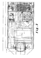
Les divers aspects de l'invention énoncés si dessus sont illustrés par un mode de réalisation du dispositif selon l'invention, représenté dans les figures 2 et 3, montrant, respectivement une vue latérale et une vue de dessus de ce mode de réalisation.The various aspects of the invention set out above are illustrated by an embodiment of the device according to the invention, shown in Figures 2 and 3, showing, respectively a side view and a top view of this embodiment.
Claims (12)
Priority Applications (9)
| Application Number | Priority Date | Filing Date | Title |
|---|---|---|---|
| EP06114251A EP1857363A1 (en) | 2006-05-19 | 2006-05-19 | Temperature regulating device |
| AT07729284T ATE461109T1 (en) | 2006-05-19 | 2007-05-18 | AIR CONDITIONING UNIT AND METHOD |
| JP2009510470A JP5129238B2 (en) | 2006-05-19 | 2007-05-18 | Air conditioning unit and air conditioning method |
| US12/301,357 US9016087B2 (en) | 2006-05-19 | 2007-05-18 | Air-conditioning unit and method |
| EP07729284A EP2021247B1 (en) | 2006-05-19 | 2007-05-18 | Air conditioning unit and method |
| PCT/EP2007/054840 WO2007135103A2 (en) | 2006-05-19 | 2007-05-18 | Air-conditioning unit and method |
| CN2007800181927A CN101448702B (en) | 2006-05-19 | 2007-05-18 | Air-conditioning unit and method |
| DE602007005368T DE602007005368D1 (en) | 2006-05-19 | 2007-05-18 | AIR CONDITIONING UNIT AND METHOD |
| US14/615,372 US10132550B2 (en) | 2006-05-19 | 2015-02-05 | Air-conditioning unit and method |
Applications Claiming Priority (1)
| Application Number | Priority Date | Filing Date | Title |
|---|---|---|---|
| EP06114251A EP1857363A1 (en) | 2006-05-19 | 2006-05-19 | Temperature regulating device |
Publications (1)
| Publication Number | Publication Date |
|---|---|
| EP1857363A1 true EP1857363A1 (en) | 2007-11-21 |
Family
ID=37110225
Family Applications (2)
| Application Number | Title | Priority Date | Filing Date |
|---|---|---|---|
| EP06114251A Withdrawn EP1857363A1 (en) | 2006-05-19 | 2006-05-19 | Temperature regulating device |
| EP07729284A Active EP2021247B1 (en) | 2006-05-19 | 2007-05-18 | Air conditioning unit and method |
Family Applications After (1)
| Application Number | Title | Priority Date | Filing Date |
|---|---|---|---|
| EP07729284A Active EP2021247B1 (en) | 2006-05-19 | 2007-05-18 | Air conditioning unit and method |
Country Status (7)
| Country | Link |
|---|---|
| US (2) | US9016087B2 (en) |
| EP (2) | EP1857363A1 (en) |
| JP (1) | JP5129238B2 (en) |
| CN (1) | CN101448702B (en) |
| AT (1) | ATE461109T1 (en) |
| DE (1) | DE602007005368D1 (en) |
| WO (1) | WO2007135103A2 (en) |
Families Citing this family (38)
| Publication number | Priority date | Publication date | Assignee | Title |
|---|---|---|---|---|
| JP5819814B2 (en) * | 2009-03-20 | 2015-11-24 | アクサ パワー アンパーツゼルスカブ | Pre-adjustable air unit with variable frequency drive |
| CN102421668B (en) * | 2009-03-20 | 2015-12-16 | Axa能源有限责任公司 | There is the pretreated air device of self contained refrigeration module |
| US20110113803A1 (en) * | 2009-05-14 | 2011-05-19 | Halla Climate Control Corp. | Multi-evaporation system |
| KR101220116B1 (en) * | 2009-12-04 | 2013-01-11 | 한라공조주식회사 | Multi-Evaporation System |
| US8366377B2 (en) * | 2010-04-09 | 2013-02-05 | Trane International Inc. | FC fan flow measurement system using a curved inlet cone and pressure sensor |
| AU2011312647A1 (en) | 2010-09-28 | 2013-04-11 | Carrier Corporation | Operation of transport refrigeration systems to prevent engine stall and overload |
| DE102012201223A1 (en) * | 2012-01-27 | 2013-08-01 | Airbus Operations Gmbh | Heat exchanger for cooling air, heating for one and galley with such a heat exchanger |
| US20140165636A1 (en) * | 2012-12-18 | 2014-06-19 | Huawei Technologies Co., Ltd. | Precise Air Conditioning System Fan Control Method and Apparatus, and Precise Air Conditioning System |
| ES2396899B1 (en) * | 2013-01-11 | 2013-11-22 | Thyssenkrupp Airport Services, S.L. | Device for the extraction and collection of air conditioning hoses |
| CN103968478B (en) | 2013-02-01 | 2018-02-23 | Lg电子株式会社 | Cooling system and its control method |
| SE539172C2 (en) * | 2013-03-13 | 2017-05-02 | Smart Climate Scandinavian Ab | Air conditioning intended to be temporarily connected to at least one aircraft |
| JP2014228188A (en) * | 2013-05-22 | 2014-12-08 | 三菱電機株式会社 | Air conditioning system |
| CN104442273A (en) * | 2013-09-17 | 2015-03-25 | 北汽福田汽车股份有限公司 | Automotive air-conditioning system and control method thereof |
| CN103851729A (en) * | 2014-02-10 | 2014-06-11 | 中船重工天禾船舶设备江苏有限公司 | Aviation air conditioning vehicle system for ship |
| US20160023770A1 (en) * | 2014-07-25 | 2016-01-28 | Nathan Thompson | Air heating apparatus useful for heating an aircraft interior |
| US10941968B2 (en) * | 2015-08-24 | 2021-03-09 | Ingersoll-Rand Industrial U.S., Inc. | Refrigerated dryer power saving controls |
| JP6124962B2 (en) * | 2015-08-31 | 2017-05-10 | 株式会社トクヤマ | Air conditioning method for aircraft and air conditioning system used in the method |
| USD809639S1 (en) | 2016-03-17 | 2018-02-06 | Denis Chiasson | Casing for an air conditioning unit |
| US10576806B1 (en) * | 2016-03-17 | 2020-03-03 | DClimate, Inc. | Auxiliary HVAC system for vehicle sleeper compartment |
| US20180002037A1 (en) * | 2016-06-29 | 2018-01-04 | John Bean Technologies Corporation | Integrated mobile ground support system for servicing aircraft |
| US10589874B2 (en) * | 2016-06-29 | 2020-03-17 | John Bean Technologies Corporation | Variable pneumatic output with constant electrical output driven by a single engine |
| US10141829B2 (en) | 2016-06-29 | 2018-11-27 | John Bean Technologies Corporation | Multiple power topologies from single power generator |
| US20180080696A1 (en) * | 2016-09-22 | 2018-03-22 | Bruce Luchner | Variable Refrigerant Flow System with Decoupled Refrigerant and Air Distribution Subsystems |
| US10856449B2 (en) * | 2016-12-02 | 2020-12-01 | Dell Products L.P. | Dynamic cooling system |
| USD847314S1 (en) | 2017-07-14 | 2019-04-30 | Denis Chiasson | Air conditioning unit |
| CN107270517B (en) * | 2017-07-26 | 2019-12-10 | 美的集团武汉制冷设备有限公司 | Air conditioning system, and control device and method of air conditioning system |
| ES2651189B8 (en) * | 2017-08-04 | 2022-03-16 | Adelte Airport Tech S L | AIR CONDITIONING EQUIPMENT FOR THE INTERIOR OF AIRCRAFT OR SIMILAR |
| JP6429959B2 (en) * | 2017-08-17 | 2018-11-28 | 三菱電機株式会社 | Air conditioning system |
| JP6997558B2 (en) * | 2017-08-24 | 2022-01-17 | サンデン・オートモーティブクライメイトシステム株式会社 | Vehicle air conditioner |
| US10782034B2 (en) * | 2017-12-13 | 2020-09-22 | RK Mechanical, Inc. | System for conditioning an airflow using a portable closed loop cooling system |
| CN112013523A (en) * | 2019-05-28 | 2020-12-01 | 麦克维尔空调制冷(武汉)有限公司 | Method and device for controlling temperature of frequency converter of refrigeration equipment and air conditioning system |
| CN111207450B (en) * | 2020-01-14 | 2021-04-16 | 珠海格力电器股份有限公司 | Air conditioning system and control method thereof |
| CN111578553A (en) * | 2020-05-25 | 2020-08-25 | 中国建筑西北设计研究院有限公司 | Aircraft ground air conditioning system |
| US11739987B2 (en) * | 2020-06-02 | 2023-08-29 | Jr Koop, Inc. | Dual integrated air heating system |
| CN111970903B (en) * | 2020-08-18 | 2022-06-07 | 中国电子科技集团公司第三十八研究所 | Multi-cycle air conditioner for radar and control method thereof |
| US20220177141A1 (en) * | 2020-12-09 | 2022-06-09 | Hamilton Sundstrand Corporation | Recirculation ground maintenance mode |
| CN115266025A (en) * | 2022-06-29 | 2022-11-01 | 新菲光通信技术有限公司 | Temperature testing device and temperature testing system |
| CN115384804A (en) * | 2022-10-28 | 2022-11-25 | 成都长空飞宇航空科技有限公司 | Combined type airplane ground air conditioning unit |
Citations (5)
| Publication number | Priority date | Publication date | Assignee | Title |
|---|---|---|---|---|
| DE3314763A1 (en) * | 1983-04-23 | 1984-10-25 | Hydro Gerätebau GmbH & Co KG Hebezeuge, 7616 Biberach | Appliance for the external ventilation and air-conditioning of aircraft or the like on the ground |
| US5031690A (en) * | 1989-07-21 | 1991-07-16 | Bfm Transport Dynamics Corp. | Portable unitary aircraft air conditioner and heater |
| US5099652A (en) * | 1989-12-20 | 1992-03-31 | Kabushiki Kaisha Toshiba | Portable type air conditioning apparatus |
| JPH10122607A (en) * | 1996-10-21 | 1998-05-15 | Shintoukiyou Kokusai Kuukou Kodan | On-ground air conditioning system for airplane |
| US20040045308A1 (en) * | 2002-07-31 | 2004-03-11 | Field Ella S. | Portable air cooling system |
Family Cites Families (76)
| Publication number | Priority date | Publication date | Assignee | Title |
|---|---|---|---|---|
| US2031690A (en) * | 1934-11-21 | 1936-02-25 | Bendix Prod Corp | Brake shield |
| US2111905A (en) * | 1935-02-08 | 1938-03-22 | Thermal Engineering Corp | Railway car air conditioning system |
| US2113359A (en) * | 1936-03-23 | 1938-04-05 | Gen American Precooling Corp | Freezing apparatus |
| US2311622A (en) * | 1940-08-03 | 1943-02-23 | Gen Motors Corp | Refrigerating apparatus |
| US2630688A (en) * | 1950-06-02 | 1953-03-10 | Kenneth C Merkling | Means for furnishing refrigeration to mobile units |
| US2746372A (en) * | 1951-10-31 | 1956-05-22 | Willis E Smith | Air conditioner for automobiles |
| US2766439A (en) * | 1953-09-16 | 1956-10-09 | Cab Controi Company | Combination refrigerating control and signaling device |
| US3150498A (en) * | 1962-03-08 | 1964-09-29 | Ray Winther Company | Method and apparatus for defrosting refrigeration systems |
| US3638444A (en) * | 1970-02-12 | 1972-02-01 | Gulf & Western Metals Forming | Hot gas refrigeration defrost structure and method |
| US3777506A (en) * | 1972-05-08 | 1973-12-11 | Camper Comfort Corp | Portable air conditioner apparatus |
| US3786859A (en) * | 1972-06-19 | 1974-01-22 | W Day | Temperature and humidity control and apparatus for residential buildings |
| US4101100A (en) * | 1976-07-28 | 1978-07-18 | Value Engineering Company | Aircraft flight line servicing system |
| US4450900A (en) * | 1981-02-19 | 1984-05-29 | Norman Nathan | Mobile air conditioning unit |
| DE3210884A1 (en) * | 1981-03-27 | 1982-10-14 | Nippondenso Co., Ltd., Kariya, Aichi | COOLING SYSTEM |
| JPS6032835Y2 (en) * | 1981-05-22 | 1985-10-01 | 富士重工業株式会社 | Aircraft ground air conditioning system |
| US4835977A (en) * | 1983-11-18 | 1989-06-06 | Teledyne Industries, Inc. | Apparatus and method of air-conditioning parked aircraft |
| JPS60147073A (en) * | 1984-01-11 | 1985-08-02 | 富士重工業株式会社 | Ground air conditioner for aircraft |
| US4540118A (en) * | 1984-04-11 | 1985-09-10 | R. J. Reynolds Tobacco Company | Variable air volume air conditioning system |
| JPS63176968A (en) * | 1987-01-14 | 1988-07-21 | ダイキン工業株式会社 | Low-temperature protective device for air conditioner |
| US5428966A (en) * | 1988-01-21 | 1995-07-04 | Alsenz; Richard H. | Refrigeration system utilizing an expansion device in the evaporator |
| US4901538A (en) * | 1988-07-13 | 1990-02-20 | James Anthony | Portable temperature maintenance system |
| US4888958A (en) * | 1988-11-30 | 1989-12-26 | Ella Gregory R | Cooling apparatus for low air loss therapy beds |
| JPH02171562A (en) * | 1988-12-26 | 1990-07-03 | Toshiba Corp | Freezing cycle device |
| JP2865707B2 (en) * | 1989-06-14 | 1999-03-08 | 株式会社日立製作所 | Refrigeration equipment |
| US5150581A (en) * | 1991-06-24 | 1992-09-29 | Baltimore Aircoil Company | Head pressure controller for air conditioning and refrigeration systems |
| US5203179A (en) * | 1992-03-04 | 1993-04-20 | Ecoair Corporation | Control system for an air conditioning/refrigeration system |
| JP2936960B2 (en) * | 1993-06-14 | 1999-08-23 | 日産自動車株式会社 | Heat pump type air conditioner for vehicles |
| JPH07208773A (en) * | 1994-01-13 | 1995-08-11 | Fuji Heavy Ind Ltd | Ground air conditioner for air plane having high pressure air supplying system |
| DE69533120D1 (en) * | 1994-05-30 | 2004-07-15 | Mitsubishi Electric Corp | Coolant circulation system |
| US5711159A (en) * | 1994-09-07 | 1998-01-27 | General Electric Company | Energy-efficient refrigerator control system |
| US6047557A (en) * | 1995-06-07 | 2000-04-11 | Copeland Corporation | Adaptive control for a refrigeration system using pulse width modulated duty cycle scroll compressor |
| JP3623060B2 (en) * | 1996-10-02 | 2005-02-23 | 株式会社大気社 | Room pressure control system |
| US6405549B1 (en) * | 1998-11-12 | 2002-06-18 | Do Enterprises, Llc | Portable heating unit using a refrigerant circuit movable within a room |
| JP2000272335A (en) * | 1999-03-23 | 2000-10-03 | Sanden Corp | Air conditioner for vehicle |
| FR2808741B1 (en) * | 2000-05-15 | 2002-12-27 | Peugeot Citroen Automobiles Sa | THERMAL REGULATION DEVICE FOR A MOTOR VEHICLE AND METHODS FOR IMPLEMENTING THE DEVICE |
| US6415619B1 (en) * | 2001-03-09 | 2002-07-09 | Hewlett-Packard Company | Multi-load refrigeration system with multiple parallel evaporators |
| JP4608799B2 (en) * | 2001-04-05 | 2011-01-12 | 澁谷工業株式会社 | Indoor pressure control device |
| JP2003106627A (en) * | 2001-09-28 | 2003-04-09 | Matsushita Electric Ind Co Ltd | Air flow control method for air conditioner |
| US6595012B2 (en) * | 2001-09-29 | 2003-07-22 | Alexander P Rafalovich | Climate control system |
| US6792767B1 (en) * | 2002-10-21 | 2004-09-21 | Aaon Inc. | Controls for air conditioner |
| US6983889B2 (en) * | 2003-03-21 | 2006-01-10 | Home Comfort Zones, Inc. | Forced-air zone climate control system for existing residential houses |
| KR100557039B1 (en) * | 2003-10-16 | 2006-03-03 | 엘지전자 주식회사 | The method for control of airconditioner |
| US7331852B2 (en) * | 2003-06-12 | 2008-02-19 | Ezell George D | Method and apparatus for sampling and controlling ventilation airflow into a structure |
| JP3757967B2 (en) * | 2003-08-25 | 2006-03-22 | ダイキン工業株式会社 | Refrigeration equipment |
| KR101013373B1 (en) * | 2003-08-28 | 2011-02-14 | 삼성전자주식회사 | Air Conditioner |
| US7159413B2 (en) * | 2003-10-21 | 2007-01-09 | Delaware Capital Formation, Inc. | Modular refrigeration system |
| US20050126190A1 (en) * | 2003-12-10 | 2005-06-16 | Alexander Lifson | Loss of refrigerant charge and expansion valve malfunction detection |
| JP4425679B2 (en) * | 2004-03-25 | 2010-03-03 | 三菱電機株式会社 | Air conditioner |
| JP2005283078A (en) * | 2004-03-31 | 2005-10-13 | Mitsubishi Heavy Ind Ltd | Air conditioner |
| KR101073501B1 (en) * | 2004-05-18 | 2011-10-17 | 삼성전자주식회사 | A air conditioner for multi-step driving |
| JP4613526B2 (en) * | 2004-06-23 | 2011-01-19 | 株式会社デンソー | Supercritical heat pump cycle equipment |
| US7353660B2 (en) * | 2004-09-13 | 2008-04-08 | Carrier Corporation | Multi-temperature cooling system with unloading |
| US7380404B2 (en) * | 2005-01-05 | 2008-06-03 | Carrier Corporation | Method and control for determining low refrigerant charge |
| JP4626531B2 (en) * | 2005-04-01 | 2011-02-09 | 株式会社デンソー | Ejector refrigeration cycle |
| US7895854B2 (en) * | 2005-06-01 | 2011-03-01 | Hewlett-Packard Development Company, L.P. | Refrigeration system with parallel evaporators and variable speed compressor |
| US7478539B2 (en) * | 2005-06-24 | 2009-01-20 | Hussmann Corporation | Two-stage linear compressor |
| US7850931B2 (en) * | 2005-08-11 | 2010-12-14 | American Sterilizer Company | Self-contained deactivation device |
| US7765831B2 (en) * | 2005-09-30 | 2010-08-03 | Thermo King Corporation | Temperature control system and method of operating same |
| US7461516B2 (en) * | 2005-11-22 | 2008-12-09 | Illinois Tool Works Inc. | Modular aircraft ground support cart |
| FR2897340B1 (en) * | 2006-02-10 | 2008-05-09 | Airbus France Sas | DEVICE FOR SUPPLYING ELECTRICITY AND AIR FROM AN AIRCRAFT ON THE GROUND |
| US7685838B2 (en) * | 2006-03-09 | 2010-03-30 | Dew Engineering And Development Ulc | Ground-based aircraft air conditioner with thermal storage |
| US20080006050A1 (en) * | 2006-05-12 | 2008-01-10 | Imi Cornelius Inc. | Multiple barrel frozen product dispenser |
| JP4389927B2 (en) * | 2006-12-04 | 2009-12-24 | ダイキン工業株式会社 | Air conditioner |
| US7802443B2 (en) * | 2007-04-13 | 2010-09-28 | Air Innovations, Inc. | Total room air purification system with air conditioning, filtration and ventilation |
| JP4285583B2 (en) * | 2007-05-30 | 2009-06-24 | ダイキン工業株式会社 | Air conditioner |
| US9097449B2 (en) * | 2007-09-28 | 2015-08-04 | Hobart Brothers Company | Pressure based control of parallel compressors in multiple refrigeration units |
| US8117864B2 (en) * | 2007-10-31 | 2012-02-21 | Illinois Tool Works Inc. | Compact, modularized air conditioning system that can be mounted upon an airplane ground support equipment cart |
| US8037714B2 (en) * | 2007-10-31 | 2011-10-18 | Illinois Tool Works Inc. | Adjustable air conditioning control system for a universal airplane ground support equipment cart |
| US20090107657A1 (en) * | 2007-10-31 | 2009-04-30 | Montminy Jeffrey E | Adjustable cooling system for airplane electronics |
| US8055388B2 (en) * | 2007-10-31 | 2011-11-08 | Illinois Tool Works Inc. | Maintenance and control system for ground support equipment |
| US8047555B2 (en) * | 2007-10-31 | 2011-11-01 | Illinois Tool Works Inc. | Airplane ground support equipment cart having extractable modules and a generator module that is seperable from power conversion and air conditioning modules |
| US8020391B2 (en) * | 2007-11-28 | 2011-09-20 | Hill Phoenix, Inc. | Refrigeration device control system |
| US9492314B2 (en) * | 2009-12-18 | 2016-11-15 | Trailerlogic, Llc | System for altering and maintaining temperatures of objects |
| JP2012122670A (en) * | 2010-12-08 | 2012-06-28 | Daikin Industries Ltd | Air conditioner |
| JP2012233676A (en) * | 2011-04-21 | 2012-11-29 | Denso Corp | Heat pump cycle |
| US9511870B2 (en) * | 2014-03-13 | 2016-12-06 | Avicorp Middle East Fzco | Independently controlled dual outlet aircraft PCAir unit |
-
2006
- 2006-05-19 EP EP06114251A patent/EP1857363A1/en not_active Withdrawn
-
2007
- 2007-05-18 EP EP07729284A patent/EP2021247B1/en active Active
- 2007-05-18 CN CN2007800181927A patent/CN101448702B/en not_active Expired - Fee Related
- 2007-05-18 WO PCT/EP2007/054840 patent/WO2007135103A2/en active Application Filing
- 2007-05-18 US US12/301,357 patent/US9016087B2/en active Active
- 2007-05-18 AT AT07729284T patent/ATE461109T1/en not_active IP Right Cessation
- 2007-05-18 DE DE602007005368T patent/DE602007005368D1/en active Active
- 2007-05-18 JP JP2009510470A patent/JP5129238B2/en not_active Expired - Fee Related
-
2015
- 2015-02-05 US US14/615,372 patent/US10132550B2/en not_active Expired - Fee Related
Patent Citations (5)
| Publication number | Priority date | Publication date | Assignee | Title |
|---|---|---|---|---|
| DE3314763A1 (en) * | 1983-04-23 | 1984-10-25 | Hydro Gerätebau GmbH & Co KG Hebezeuge, 7616 Biberach | Appliance for the external ventilation and air-conditioning of aircraft or the like on the ground |
| US5031690A (en) * | 1989-07-21 | 1991-07-16 | Bfm Transport Dynamics Corp. | Portable unitary aircraft air conditioner and heater |
| US5099652A (en) * | 1989-12-20 | 1992-03-31 | Kabushiki Kaisha Toshiba | Portable type air conditioning apparatus |
| JPH10122607A (en) * | 1996-10-21 | 1998-05-15 | Shintoukiyou Kokusai Kuukou Kodan | On-ground air conditioning system for airplane |
| US20040045308A1 (en) * | 2002-07-31 | 2004-03-11 | Field Ella S. | Portable air cooling system |
Also Published As
| Publication number | Publication date |
|---|---|
| US9016087B2 (en) | 2015-04-28 |
| CN101448702A (en) | 2009-06-03 |
| DE602007005368D1 (en) | 2010-04-29 |
| US20100031676A1 (en) | 2010-02-11 |
| JP5129238B2 (en) | 2013-01-30 |
| WO2007135103A2 (en) | 2007-11-29 |
| EP2021247B1 (en) | 2010-03-17 |
| EP2021247A2 (en) | 2009-02-11 |
| US10132550B2 (en) | 2018-11-20 |
| JP2009537779A (en) | 2009-10-29 |
| ATE461109T1 (en) | 2010-04-15 |
| CN101448702B (en) | 2012-06-13 |
| WO2007135103A3 (en) | 2008-03-20 |
| US20150153092A1 (en) | 2015-06-04 |
Similar Documents
| Publication | Publication Date | Title |
|---|---|---|
| EP1857363A1 (en) | Temperature regulating device | |
| EP1599352B1 (en) | Ventilation/heating and/or air conditioning device for the passenger compartment of a motor vehicle with simultaneous cooling of air and coolant | |
| EP1999412B1 (en) | Method, device and system for heating/cooling and ventilating a premises | |
| EP1329344A1 (en) | Device for thermal management, especially for a vehicle equipped with a fuel cell | |
| FR2898544A1 (en) | AIR CONDITIONING INSTALLATION | |
| FR2884058A1 (en) | Battery`s temperature setting maintaining device for e.g. electric vehicle, has intermediate heat exchanger placed between cooling circuit and air conditioning loop of heating, ventilating and/or air conditioning installation of vehicle | |
| EP0780254A1 (en) | Vehicle supplementary heating employing the air conditioning fluid circuit | |
| FR2978532A1 (en) | Device for heating and/or air conditioning e.g. building, has derivation units allowing return air coming from building to be directed toward fresh air outlet blown in building direction, without passing through air-to-air heat exchanger | |
| EP2191206A2 (en) | Heating/air-conditioning plant with heat pump, comprising a heat transfer fluid splitter box with coupling to a plurality of heat collecting and distributing circuits | |
| FR2941521A1 (en) | Combined ventilation and water-heater installation for room e.g. garage, of dwelling, has air extraction system for modifying flow of extraction air for heating water based on operating state of water-heater | |
| FR2507295A1 (en) | GRAVITY DEFROSTING SYSTEM | |
| WO2013120828A1 (en) | Air-conditioning loop functioning as a pulse electro-thermal deicing heat pump | |
| EP1695010B1 (en) | Heating and air-conditioning device | |
| JPS6256427B2 (en) | ||
| FR2957851A1 (en) | Heating, ventilating and/or air-conditioning device for motor vehicle, has switching unit in position in which refrigerant is flown from compressor toward internal exchanger, accumulator, evaporator, external exchanger and compressor | |
| FR2969255A1 (en) | Ventilation installation e.g. double flow ventilation installation, parameterizing method for room of dwelling, involves recording nominal speed of ventilator as function of attained predetermined target value of air flow parameter | |
| EP1136760B1 (en) | Heating and air conditioning installation comprising a box with a radiant surface | |
| FR3077374A1 (en) | OPTIMIZED POSITIVE TEMPERATURE POSITIVE TEMPERATURE HEATING / DRYING AIR CONDITIONING SYSTEM, MODULE AND CORRESPONDING METHOD | |
| FR2966562A1 (en) | Air supply loop for e.g. conference room of office, has plate located between distribution chamber and nozzles chamber and between other nozzles chamber and additional air chamber | |
| JPH0914778A (en) | Air conditioner | |
| EP2057027B1 (en) | Air-conditioning system for a car | |
| FR2913755A1 (en) | Ventilation device for heat regulation system of e.g. dwelling, has turbine mounted in cylindrical case and comprising rotation shaft integrated to ventilation unit, where turbine is rotated by circulation of heat transfer fluid in case | |
| EP2891844B1 (en) | System for producing domestic hot water coupled with photovoltaic panels and method for improving the efficiency of such a system for producing domestic hot water | |
| CA2225590A1 (en) | Dual heat reclaimer air exchanger | |
| FR2896307A1 (en) | Air conditioner with heat pump has air mixing chamber fed with cold air in summer and hot air in winter located before condenser |
Legal Events
| Date | Code | Title | Description |
|---|---|---|---|
| PUAI | Public reference made under article 153(3) epc to a published international application that has entered the european phase |
Free format text: ORIGINAL CODE: 0009012 |
|
| AK | Designated contracting states |
Kind code of ref document: A1 Designated state(s): AT BE BG CH CY CZ DE DK EE ES FI FR GB GR HU IE IS IT LI LT LU LV MC NL PL PT RO SE SI SK TR |
|
| AX | Request for extension of the european patent |
Extension state: AL BA HR MK YU |
|
| AKX | Designation fees paid | ||
| REG | Reference to a national code |
Ref country code: DE Ref legal event code: 8566 |
|
| STAA | Information on the status of an ep patent application or granted ep patent |
Free format text: STATUS: THE APPLICATION IS DEEMED TO BE WITHDRAWN |
|
| 18D | Application deemed to be withdrawn |
Effective date: 20080522 |