EP1855001A1 - A gearbox for a wind turbine - Google Patents
A gearbox for a wind turbine Download PDFInfo
- Publication number
- EP1855001A1 EP1855001A1 EP07075312A EP07075312A EP1855001A1 EP 1855001 A1 EP1855001 A1 EP 1855001A1 EP 07075312 A EP07075312 A EP 07075312A EP 07075312 A EP07075312 A EP 07075312A EP 1855001 A1 EP1855001 A1 EP 1855001A1
- Authority
- EP
- European Patent Office
- Prior art keywords
- housing
- gearbox
- bearing
- elastic part
- driving shaft
- Prior art date
- Legal status (The legal status is an assumption and is not a legal conclusion. Google has not performed a legal analysis and makes no representation as to the accuracy of the status listed.)
- Granted
Links
Images


Classifications
-
- F—MECHANICAL ENGINEERING; LIGHTING; HEATING; WEAPONS; BLASTING
- F16—ENGINEERING ELEMENTS AND UNITS; GENERAL MEASURES FOR PRODUCING AND MAINTAINING EFFECTIVE FUNCTIONING OF MACHINES OR INSTALLATIONS; THERMAL INSULATION IN GENERAL
- F16H—GEARING
- F16H1/00—Toothed gearings for conveying rotary motion
- F16H1/28—Toothed gearings for conveying rotary motion with gears having orbital motion
- F16H1/48—Special means compensating for misalignment of axes, e.g. for equalising distribution of load on the face width of the teeth
-
- F—MECHANICAL ENGINEERING; LIGHTING; HEATING; WEAPONS; BLASTING
- F03—MACHINES OR ENGINES FOR LIQUIDS; WIND, SPRING, OR WEIGHT MOTORS; PRODUCING MECHANICAL POWER OR A REACTIVE PROPULSIVE THRUST, NOT OTHERWISE PROVIDED FOR
- F03D—WIND MOTORS
- F03D15/00—Transmission of mechanical power
-
- F—MECHANICAL ENGINEERING; LIGHTING; HEATING; WEAPONS; BLASTING
- F03—MACHINES OR ENGINES FOR LIQUIDS; WIND, SPRING, OR WEIGHT MOTORS; PRODUCING MECHANICAL POWER OR A REACTIVE PROPULSIVE THRUST, NOT OTHERWISE PROVIDED FOR
- F03D—WIND MOTORS
- F03D15/00—Transmission of mechanical power
- F03D15/10—Transmission of mechanical power using gearing not limited to rotary motion, e.g. with oscillating or reciprocating members
-
- F—MECHANICAL ENGINEERING; LIGHTING; HEATING; WEAPONS; BLASTING
- F03—MACHINES OR ENGINES FOR LIQUIDS; WIND, SPRING, OR WEIGHT MOTORS; PRODUCING MECHANICAL POWER OR A REACTIVE PROPULSIVE THRUST, NOT OTHERWISE PROVIDED FOR
- F03D—WIND MOTORS
- F03D80/00—Details, components or accessories not provided for in groups F03D1/00 - F03D17/00
- F03D80/70—Bearing or lubricating arrangements
-
- F—MECHANICAL ENGINEERING; LIGHTING; HEATING; WEAPONS; BLASTING
- F05—INDEXING SCHEMES RELATING TO ENGINES OR PUMPS IN VARIOUS SUBCLASSES OF CLASSES F01-F04
- F05B—INDEXING SCHEME RELATING TO WIND, SPRING, WEIGHT, INERTIA OR LIKE MOTORS, TO MACHINES OR ENGINES FOR LIQUIDS COVERED BY SUBCLASSES F03B, F03D AND F03G
- F05B2260/00—Function
- F05B2260/40—Transmission of power
- F05B2260/403—Transmission of power through the shape of the drive components
- F05B2260/4031—Transmission of power through the shape of the drive components as in toothed gearing
- F05B2260/40311—Transmission of power through the shape of the drive components as in toothed gearing of the epicyclic, planetary or differential type
-
- F—MECHANICAL ENGINEERING; LIGHTING; HEATING; WEAPONS; BLASTING
- F16—ENGINEERING ELEMENTS AND UNITS; GENERAL MEASURES FOR PRODUCING AND MAINTAINING EFFECTIVE FUNCTIONING OF MACHINES OR INSTALLATIONS; THERMAL INSULATION IN GENERAL
- F16H—GEARING
- F16H1/00—Toothed gearings for conveying rotary motion
- F16H1/28—Toothed gearings for conveying rotary motion with gears having orbital motion
- F16H1/2809—Toothed gearings for conveying rotary motion with gears having orbital motion with means for equalising the distribution of load on the planet-wheels
- F16H1/2818—Toothed gearings for conveying rotary motion with gears having orbital motion with means for equalising the distribution of load on the planet-wheels by allowing limited movement of the ring gear relative to the casing or shaft
-
- Y—GENERAL TAGGING OF NEW TECHNOLOGICAL DEVELOPMENTS; GENERAL TAGGING OF CROSS-SECTIONAL TECHNOLOGIES SPANNING OVER SEVERAL SECTIONS OF THE IPC; TECHNICAL SUBJECTS COVERED BY FORMER USPC CROSS-REFERENCE ART COLLECTIONS [XRACs] AND DIGESTS
- Y02—TECHNOLOGIES OR APPLICATIONS FOR MITIGATION OR ADAPTATION AGAINST CLIMATE CHANGE
- Y02E—REDUCTION OF GREENHOUSE GAS [GHG] EMISSIONS, RELATED TO ENERGY GENERATION, TRANSMISSION OR DISTRIBUTION
- Y02E10/00—Energy generation through renewable energy sources
- Y02E10/70—Wind energy
- Y02E10/72—Wind turbines with rotation axis in wind direction
Definitions
- the present invention concerns a gearbox for a wind turbine.
- the present invention concerns a gearbox for a wind turbine which consists of ring wheel unit provided in a housing; a driving shaft designed to be coupled to the rotor of the wind turbine and a single main bearing or a pair of main bearings which support the driving shaft such that it can be rotated in the housing, whereby the ring wheel unit is formed of a sun wheel, a planet wheel, ring wheel which is fixed to the housing in a non-rotating manner and a planet carrier which is rigidly fixed to the driving shaft.
- Such gearboxes for wind turbines are already known, whereby the driving shaft is coupled to the rotor of a wind turbine and whereby the sun wheel of the gear unit drives for example a generator.
- the housing of the gearbox is made of several pieces, whereby a first part of the housing is for example a part of the supporting structure in which a couple of main bearings are provided directly in the seatings and whereby a second part of the housing is screwed onto the supporting structure, which part comprises the actual ring wheel unit.
- the pair of main bearings is replaced by only a single main bearing, such as for example a double cone bearing.
- the aim is that the main bearing or the pair of main bearings absorb the loads on the driving shaft due to the aerodynamic wind load as well as the rotor weight and transmit these directly or via the housing of the gearbox to the supporting structure of the wind turbine.
- a disadvantage of the known embodiments is that, while the wind turbine is operational, the main bearings are subject to a certain elastic deformation under the influence of the rotor loads, which inevitably results in a certain play in the main bearings, which will cause an alignment error at the ring wheel unit which hinders the good working of the ring wheel unit.
- a result of the above-mentioned alignment error is that the plays between the flanks of the teeth of the gear wheels can be restricted in some cases or can be entirely absent or, the other way round, may increase.
- a disadvantage of all this is that an uneven load of the gear wheels is obtained and that the normal interplay of forces between the gear wheels is disturbed, which will result in the gear wheels and the bearings of the planet wheels being overloaded.
- the present invention aims to remedy one or several of the above-mentioned and other disadvantages.
- the present invention concerns a gearbox for a wind turbine of the above-mentioned type, whereby an additional bearing is provided to support the planet carrier or the driving shaft in a rotating manner in relation to the housing and whereby between the part of the housing in which the main bearing or the main bearings are provided and the part of the housing in which the additional bearing and the ring wheel are provided, there has been provided an elastic part which has a relative torsional stiffness on the one hand and which is relatively flexible on the other hand to loads in the axial direction and/or loads in a radial direction.
- An advantage of such a gearbox for a wind turbine according to the invention is that the above-mentioned alignment error that occurs as a result of deformations of the main bearings, the planet carrier, the driving shaft and/or the housing or as a result of plays can be absorbed or compensated for, as the elastic part of the housing makes it possible for the part of the housing in which the ring wheel and the additional bearing have been provided can move in an axial or radial direction in relation to the part of the housing in which the main bearings are embedded.
- the alignment between the ring wheel, the planet carrier, the planet wheels and the sun wheel improves, such that the above-mentioned negative effects due to a bad alignment are avoided.
- the ring wheel, the planet wheels and the sun wheel are placed in the axial direction between the additional bearing and a main bearing.
- the additional bearing supports the planet carrier in a place where the above-mentioned alignment error is relatively large and at a relatively large axial distance in relation to the elastic part.
- the resistance exerted by the elastic part to oppose the movement of the part of the housing in which the ring wheel and the additional bearing are situated under the influence of the alignment error, can thus be overcome relatively easily.
- the alignment error can be eliminated with only a restricted load on the additional bearing.
- the load on the additional bearing which supports the planet carrier in relation to the housing of the gear unit is mainly determined by the axial and radial stiffness of the above-mentioned elastic part.
- An advantage of this embodiment is that, by designing the elastic part with the appropriate radial or axial stiffness, for example by means of calculations in computer models or by establishing said stiffnesses by experiment, the load on the additional bearing can be restricted, such that the maximum life of this additional bearing can be guaranteed or its dimensions can be limited.
- the load on the additional bearing depends on the elasticity of the elastic part, on the distance of the elastic part to the additional bearing, but also on the elasticity of the main bearings.
- the gearbox 1 for a wind turbine 2 consists of ring wheel unit 3 provided in a housing 4; a driving shaft 5 which is coupled to the rotor 6 of the wind turbine 2 and a main bearing 7 which supports the driving shaft or rotor shaft 5 in a rotating manner in the housing 4.
- the ring wheel unit 3 consists of a planet carrier 8 on which have been provided planet wheels 9, in this case three planet wheels 9 in total, whereby these planet wheels 9 work in conjunction with a sun wheel 10 and ring wheel 11 which is fixed to the housing 4 of the gearbox 1 in a non-rotating manner.
- the planet wheels 9 can rotate in relation to the planet carrier 8 .
- the planet carrier 8 in the given example consists of a first part 12 and a second part 13, which parts are connected to each other by means of shafts 14.
- such a planet carrier 8 of what is called the "cage" type can also be made of a single piece by casting the piece in a mould.
- the sun wheel 10 is provided on a driven shaft 17, which protrudes through an opening 18 in the second part 13 of the planet carrier 8.
- the driven shaft 17 is also supported in a rotating manner in relation to the housing 4 of the gearbox 1, which is schematically represented in the figures, but only to illustrate the principle of the invention in a simple manner, by means of a bearing 19.
- this support of the driven shaft 17 is often obtained as the driven shaft 17 drives a second planetary step, whereby the bearing, which supports the planet carrier of said step in the housing 4, also provides for the support of the driven shaft 17.
- the driven shaft 17 drives for example a transmission with a hollow shaft and a gear wheel whereby, in practice, the support of the driven shaft 17 in the housing 4 again must not be directly provided for by a bearing 19.
- the planet carrier 8 is rigidly connected to the rotor shaft 5, such that the rotor shaft 5 together with the planet carrier 8 forms the actual entry of the gear unit 3.
- the aim is to transform the relatively slow rotation of the rotor shaft 5 or driving shaft 5 under the influence of the wind force, via the ring wheel unit 3, in a relatively fast rotation of the driven shaft 17, for example in order to drive a generator or a following step in the gear wheel transmission.
- the gearbox 1 is provided on a supporting structure 21 of the wind turbine 2 by means of bolts 22, in particular on the turbine cradle, whereby a direct, rigid connection between the gearbox 1 and the supporting structure 21 is realized.
- the rotor shaft 5 is in this case bearing-mounted in the housing 4 of the gearbox 1 by means of only a single main bearing 7.
- the gearbox 1 will behave differently from the gearboxes whereby the rotor shaft 5 is bearing-mounted in the supporting structure 21 by means of a pair of main bearings and whereby a spring/damper system has been provided between the gearbox 1 and the supporting structure.
- the main bearing 7 is such that the bending moments and the forces caused by the rotor weight on the rotor shaft 5 are mainly absorbed by this bearing 7 and are transmitted to the housing 4 and to the supporting structure 21, whereby the main bearing 7 also provides for an axial and radial positioning of the driving shaft 5 in the housing 4.
- a first aspect of the invention consists in also providing an additional bearing 22 which supports the planet carrier 8 in a rotating manner in relation to the housing 4 of the gearbox 1.
- Another aspect of the invention consists in providing an elastic part 23 in the housing 4 which has a relative torsional stiffness on the one hand and which is relatively flexible to loads in the axial direction AA' and/or in a radial direction RR' on the other hand.
- This elastic part 23 is placed such that the part 24 of the housing 4 in which the additional bearing 22, the ring wheel 11, as well as the driven shaft 17 are provided such that they can move somewhat in relation to the part 25 of the housing 4 in which the main bearing 7 has been provided.
- the main bearing 7 of the gearbox 1 is dimensioned large enough to absorb the bending moments and forces on the rotor shaft 5 caused by the rotor weight and the wind load and to transmit them to the housing 4 and the supporting structure 21.
- Figure 2 represents said deformations and plays in a strongly simplified manner and to an exaggerated scale by means of an angular displacement B of the rotor shaft 5.
- the planet carrier 8 is additionally supported in the housing 4 by the bearing 22 and since an elastic part 23 is provided in the housing 4 between the above-mentioned parts 24 and 25, the part 24 of the housing 4 will be able to follow the movement of the rotor shaft 5 relatively easily.
- Figure 2 again represents this in a simplified manner by displacing the part 24 over an angle B in relation to the other part 25 of the housing 4.
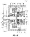
- FIGS 3 to 6 represent other embodiments of gearboxes 1 for wind turbines according to the invention.
- figure 3 consists in supporting the rotor shaft 5 not by merely one main bearing 9, but by a couple of main bearings 26 and 27.
- main bearings 26 and 27 are not integrated in a separate housing 4 of the gearbox 1 in which the ring wheel unit 3 is provided as well, but said main bearings 26 and 27 are directly provided in the supporting structure 21 of the wind turbine 2.
- the housing 4 of the gearbox 1 is partly integrated in the supporting structure 21 of the wind turbine 2.
- Figure 4 represents an intermediate form whereby two main bearings 26 and 27 are provided as well, but whereby one main bearing 26 is integrated in the housing 4 of the gear unit 1, whereas the other main bearing is integrated in the supporting structure 21.
- the housing 4 of the gearbox 1 is partly integrated in the supporting structure 21 of the wind turbine 2.
- Figure 5 represents yet another variant according to the invention, whereby the elastic part 23 is this time not provided in the housing 4 of the gearbox 1, but in the supporting structure 21.
- the ring wheel 11 the planet wheels 9 and the sun wheel 10 are placed in the axial direction AA' between the additional bearing 22 and a main bearing 7, 26 or 27.
- the load on the additional bearing 22 is mainly determined by the axial and radial stiffness of the elastic part 23 and the moment arm L or L', but also by the stiffness of the main bearing 7.
- the embodiment according to figure 6 can for example be selected to facilitate the mounting or the like.
- Figure 7 represents the elastic part 23 to a larger scale, whereby the elasticity of the elastic part 23 is obtained in this embodiment by giving this part other dimensions than the surrounding parts 24 and 25 of the housing 4.
- the thickness D of the elastic part 23 is smaller than the thickness D' of the surrounding parts 24 and 25 of the housing 4.
- Figure 8 represents a preferred alternative embodiment for the elastic part 23, whereby the elastic part 23 is provided with a cross-section which is U-shaped.
- This embodiment is particularly interesting as the elastic part 23 is very flexible when it is subjected to a force Fax in the axial direction AA', as is illustrated by means of figure 9, or to a force Frad in a radial direction RR', as is illustrated by means of figure 10.
- the elastic part 23 has a sufficient torsional stiffness, such that it can absorb the reaction moments acting on the ring wheel 11 without any problems.
- Figure 11 represents yet another embodiment for the elastic part 23, whereby this part 23 is this time formed by providing the housing 4 with a certain molding.
- Such a molding can be formed by omitting certain parts of the housing 4 so as to obtain the required radial and axial flexibility, and it does not need to be uniform over the entire perimeter of the housing 4, for example.
- the elasticity is obtained by making the part 23 of the housing 4 of a material which is more elastic than the surrounding parts 24 and 25 of the housing 4, for example of a synthetic material or the like.
- the elastic part 23 is not necessarily uniform over the perimeter.
Landscapes
- Engineering & Computer Science (AREA)
- General Engineering & Computer Science (AREA)
- Mechanical Engineering (AREA)
- Life Sciences & Earth Sciences (AREA)
- Sustainable Development (AREA)
- Sustainable Energy (AREA)
- Chemical & Material Sciences (AREA)
- Combustion & Propulsion (AREA)
- Wind Motors (AREA)
- General Details Of Gearings (AREA)
Abstract
Description
- The present invention concerns a gearbox for a wind turbine.
- In particular, the present invention concerns a gearbox for a wind turbine which consists of ring wheel unit provided in a housing; a driving shaft designed to be coupled to the rotor of the wind turbine and a single main bearing or a pair of main bearings which support the driving shaft such that it can be rotated in the housing, whereby the ring wheel unit is formed of a sun wheel, a planet wheel, ring wheel which is fixed to the housing in a non-rotating manner and a planet carrier which is rigidly fixed to the driving shaft.
- Such gearboxes for wind turbines are already known, whereby the driving shaft is coupled to the rotor of a wind turbine and whereby the sun wheel of the gear unit drives for example a generator.
- In the conventional embodiments, the housing of the gearbox is made of several pieces, whereby a first part of the housing is for example a part of the supporting structure in which a couple of main bearings are provided directly in the seatings and whereby a second part of the housing is screwed onto the supporting structure, which part comprises the actual ring wheel unit.
- It is also known to embed the main bearings as well as the ring wheel unit in a separate housing which is provided on the supporting structure afterwards.
- These are what are called integrated main bearings.
- In case of a further integration, the pair of main bearings is replaced by only a single main bearing, such as for example a double cone bearing.
- The aim is that the main bearing or the pair of main bearings absorb the loads on the driving shaft due to the aerodynamic wind load as well as the rotor weight and transmit these directly or via the housing of the gearbox to the supporting structure of the wind turbine.
- A disadvantage of the known embodiments is that, while the wind turbine is operational, the main bearings are subject to a certain elastic deformation under the influence of the rotor loads, which inevitably results in a certain play in the main bearings, which will cause an alignment error at the ring wheel unit which hinders the good working of the ring wheel unit.
- For, a result of the above-mentioned alignment error is that the plays between the flanks of the teeth of the gear wheels can be restricted in some cases or can be entirely absent or, the other way round, may increase.
- A disadvantage of all this is that an uneven load of the gear wheels is obtained and that the normal interplay of forces between the gear wheels is disturbed, which will result in the gear wheels and the bearings of the planet wheels being overloaded.
- Also, the present invention aims to remedy one or several of the above-mentioned and other disadvantages.
- To this end, the present invention concerns a gearbox for a wind turbine of the above-mentioned type, whereby an additional bearing is provided to support the planet carrier or the driving shaft in a rotating manner in relation to the housing and whereby between the part of the housing in which the main bearing or the main bearings are provided and the part of the housing in which the additional bearing and the ring wheel are provided, there has been provided an elastic part which has a relative torsional stiffness on the one hand and which is relatively flexible on the other hand to loads in the axial direction and/or loads in a radial direction.
- An advantage of such a gearbox for a wind turbine according to the invention is that the above-mentioned alignment error that occurs as a result of deformations of the main bearings, the planet carrier, the driving shaft and/or the housing or as a result of plays can be absorbed or compensated for, as the elastic part of the housing makes it possible for the part of the housing in which the ring wheel and the additional bearing have been provided can move in an axial or radial direction in relation to the part of the housing in which the main bearings are embedded.
- As a result, the alignment between the ring wheel, the planet carrier, the planet wheels and the sun wheel improves, such that the above-mentioned negative effects due to a bad alignment are avoided.
- According to a preferred embodiment of a gearbox according to the invention, the ring wheel, the planet wheels and the sun wheel are placed in the axial direction between the additional bearing and a main bearing.
- In this embodiment, the additional bearing supports the planet carrier in a place where the above-mentioned alignment error is relatively large and at a relatively large axial distance in relation to the elastic part.
- The resistance exerted by the elastic part to oppose the movement of the part of the housing in which the ring wheel and the additional bearing are situated under the influence of the alignment error, can thus be overcome relatively easily.
- For, thanks to the elasticity of the elastic part and the large distance between this elastic part and the additional bearing, the alignment error can be eliminated with only a restricted load on the additional bearing.
- In this manner, the planet wheels, the ring wheel and the sun wheel can be correctly aligned again in an efficient manner.
- According to another preferred embodiment of a gearbox according to the invention, the load on the additional bearing which supports the planet carrier in relation to the housing of the gear unit is mainly determined by the axial and radial stiffness of the above-mentioned elastic part.
- An advantage of this embodiment is that, by designing the elastic part with the appropriate radial or axial stiffness, for example by means of calculations in computer models or by establishing said stiffnesses by experiment, the load on the additional bearing can be restricted, such that the maximum life of this additional bearing can be guaranteed or its dimensions can be limited.
- In general, it should be noted that the load on the additional bearing depends on the elasticity of the elastic part, on the distance of the elastic part to the additional bearing, but also on the elasticity of the main bearings.
- For, the larger the stiffness of the main bearings, the smaller the alignment error will be at the additional bearing, the less the elastic part must be deformed so as to compensate the alignment error, the less load the additional bearing will thus be subjected to.
- In order to better explain the characteristics of the invention, the following preferred embodiments of a gearbox for a wind turbine according to the invention are described as an example only without being limitative in any way, with reference to the accompanying drawings, in which:
- figure 1 schematically represents a first embodiment of a gearbox according to the invention, as a section, whereby the driving shaft is supported by means of a single main bearing which is integrated together with the rest of the ring wheel unit in a separate housing;
- figure 2 illustrates the working of a gearbox according to figure 1;
- figure 3, analogous to figure 1, represents an embodiment of a gearbox according to the invention whereby the rotor is supported by two main bearings provided directly in the turbine cradle;
- figure 4 represents an embodiment which is a mixture of the embodiments from figures 1 and 3, whereby two main bearings support the rotor:
- a first main bearing provided in the turbine cradle and a second main bearing which is integrated together with the rest of the ring wheel unit in a separate housing;
- figure 5 represents an alternative embodiment for the embodiments from figures 1, 2 and 4, whereby an elastic part is provided in the turbine cradle;
- figure 6 represents an alternative for the embodiment of figure 1, whereby the additional bearing has been provided closer to the main bearing;
- figure 7 represents the part indicated by F7 in figure 1 to a larger scale;
- figure 8 represents an alternative embodiment for the part of figure 7;
- figures 9 and 10 illustrate the working of the embodiment of figure 8; and,
- figures 11 and 12 represent yet other embodiments for the part of figure 7.
- The
gearbox 1 for awind turbine 2 according to the invention represented in figure 1 consists ofring wheel unit 3 provided in ahousing 4; adriving shaft 5 which is coupled to therotor 6 of thewind turbine 2 and amain bearing 7 which supports the driving shaft orrotor shaft 5 in a rotating manner in thehousing 4. - The
ring wheel unit 3 consists of aplanet carrier 8 on which have been providedplanet wheels 9, in this case threeplanet wheels 9 in total, whereby theseplanet wheels 9 work in conjunction with asun wheel 10 andring wheel 11 which is fixed to thehousing 4 of thegearbox 1 in a non-rotating manner. - The
planet wheels 9 can rotate in relation to theplanet carrier 8 . - To this end, the
planet carrier 8 in the given example consists of afirst part 12 and asecond part 13, which parts are connected to each other by means ofshafts 14. - As an alternative, such a
planet carrier 8 of what is called the "cage" type can also be made of a single piece by casting the piece in a mould. - On these
shafts 14, theplanet wheels 9 are bearing-mounted by means ofbearings - The
sun wheel 10 is provided on a drivenshaft 17, which protrudes through an opening 18 in thesecond part 13 of theplanet carrier 8. - The driven
shaft 17 is also supported in a rotating manner in relation to thehousing 4 of thegearbox 1, which is schematically represented in the figures, but only to illustrate the principle of the invention in a simple manner, by means of abearing 19. - In practice, this support of the driven
shaft 17 is often obtained as the drivenshaft 17 drives a second planetary step, whereby the bearing, which supports the planet carrier of said step in thehousing 4, also provides for the support of the drivenshaft 17. - In other embodiments, the driven
shaft 17 drives for example a transmission with a hollow shaft and a gear wheel whereby, in practice, the support of the drivenshaft 17 in thehousing 4 again must not be directly provided for by abearing 19. - Naturally, many alternatives are possible.
- Further, the
planet carrier 8 is rigidly connected to therotor shaft 5, such that therotor shaft 5 together with theplanet carrier 8 forms the actual entry of thegear unit 3. - Of course, the aim is to transform the relatively slow rotation of the
rotor shaft 5 or drivingshaft 5 under the influence of the wind force, via thering wheel unit 3, in a relatively fast rotation of the drivenshaft 17, for example in order to drive a generator or a following step in the gear wheel transmission. - In the given embodiment, the
gearbox 1 is provided on a supportingstructure 21 of thewind turbine 2 by means ofbolts 22, in particular on the turbine cradle, whereby a direct, rigid connection between thegearbox 1 and the supportingstructure 21 is realized. - The
rotor shaft 5 is in this case bearing-mounted in thehousing 4 of thegearbox 1 by means of only a single main bearing 7. - Thanks to the rigid connection between the
housing 4 and the supportingstructure 21 and the integrated bearing 7 of therotor shaft 5, thegearbox 1 according to the invention will behave differently from the gearboxes whereby therotor shaft 5 is bearing-mounted in the supportingstructure 21 by means of a pair of main bearings and whereby a spring/damper system has been provided between thegearbox 1 and the supporting structure. - The
main bearing 7 is such that the bending moments and the forces caused by the rotor weight on therotor shaft 5 are mainly absorbed by this bearing 7 and are transmitted to thehousing 4 and to the supportingstructure 21, whereby themain bearing 7 also provides for an axial and radial positioning of the drivingshaft 5 in thehousing 4. - A first aspect of the invention consists in also providing an
additional bearing 22 which supports theplanet carrier 8 in a rotating manner in relation to thehousing 4 of thegearbox 1. - Another aspect of the invention consists in providing an
elastic part 23 in thehousing 4 which has a relative torsional stiffness on the one hand and which is relatively flexible to loads in the axial direction AA' and/or in a radial direction RR' on the other hand. - This
elastic part 23 is placed such that thepart 24 of thehousing 4 in which the additional bearing 22, thering wheel 11, as well as the drivenshaft 17 are provided such that they can move somewhat in relation to thepart 25 of thehousing 4 in which themain bearing 7 has been provided. - The principle of a
gearbox 1 according to the invention is simple and is illustrated hereafter by means of figure 2. - The main bearing 7 of the
gearbox 1 is dimensioned large enough to absorb the bending moments and forces on therotor shaft 5 caused by the rotor weight and the wind load and to transmit them to thehousing 4 and the supportingstructure 21. - However, because of the extent of the above-mentioned forces that are active on the
rotor shaft 5, it is inevitable that the main bearing 7, therotor shaft 5, theplanet carrier 8 and/or thehousing 4 of thegearbox 1 undergo a certain deformation. - Moreover, there is in general also a certain play in the main bearing 7.
- Figure 2 represents said deformations and plays in a strongly simplified manner and to an exaggerated scale by means of an angular displacement B of the
rotor shaft 5. - Naturally, in practice the situation will be far more complex.
- If no
additional bearing 22 orelastic part 23 was provided, as is the case with the known gearboxes, due to the above-mentioned effects, after applying a load, the driving shaft orrotor shaft 5 would no longer be symmetrically aligned to the drivenshaft 17, such that a certain alignment error B would occur between thedriving shaft 5 and the drivenshaft 17. - As a result of such an alignment error B, the
planet wheels 9 would no longer be well aligned in relation to thering wheel 11 and thesun wheel 10, which would hinder the good working order of thering wheel unit 3. - However, since according to the invention the
planet carrier 8 is additionally supported in thehousing 4 by thebearing 22 and since anelastic part 23 is provided in thehousing 4 between the above-mentionedparts part 24 of thehousing 4 will be able to follow the movement of therotor shaft 5 relatively easily. - Figure 2 again represents this in a simplified manner by displacing the
part 24 over an angle B in relation to theother part 25 of thehousing 4. - It is clear that in this manner, the
different gear wheels ring wheel unit 3, as well as the drivingshaft 5 and the drivenshaft 17 are again well aligned in relation to each other, which was one of the aims of the invention. - Figures 3 to 6 represent other embodiments of
gearboxes 1 for wind turbines according to the invention. - The alternative of figure 3 consists in supporting the
rotor shaft 5 not by merely onemain bearing 9, but by a couple ofmain bearings - Moreover, said
main bearings separate housing 4 of thegearbox 1 in which thering wheel unit 3 is provided as well, but saidmain bearings structure 21 of thewind turbine 2. - In other words, the
housing 4 of thegearbox 1 is partly integrated in the supportingstructure 21 of thewind turbine 2. - Naturally, this does not change the working of the
gearbox 1 in any way, and an alignment error B can be remedied just as well with this embodiment. - Figure 4 represents an intermediate form whereby two
main bearings main bearing 26 is integrated in thehousing 4 of thegear unit 1, whereas the other main bearing is integrated in the supportingstructure 21. - Again, put the other way, the
housing 4 of thegearbox 1 is partly integrated in the supportingstructure 21 of thewind turbine 2. - Naturally, the working of this embodiment is entirely analogous to the preceding embodiments.
- Figure 5 represents yet another variant according to the invention, whereby the
elastic part 23 is this time not provided in thehousing 4 of thegearbox 1, but in the supportingstructure 21. - Again, a part of the
housing 4 of thegearbox 1 is integrated in the supportingstructure 21 in this case. - This does not alter the principle of the invention, as long as it is made sure that the
part 24, formed of thehousing 4 of thegearbox 1 and the part 29 of the supportingstructure 21 between theelastic part 23 and thehousing 4, in which thering wheel 11 and theadditional bearing 2 are held, can follow the movement of the drivingshaft 5 in relation to thepart 25 of the supportingstructure 21 in which themain bearings - This is clearly the case in the embodiment shown.
- In all the embodiments discusses until now, the
ring wheel 11, theplanet wheels 9 and thesun wheel 10 are placed in the axial direction AA' between theadditional bearing 22 and amain bearing - In the embodiment of figure 6, however, an
additional bearing 22 has been provided between thering wheel unit 3 and the supportingstructure 21. - If the
elastic part 23 is placed right, it is made sure that thepart 24 of thehousing 4, which contains saidadditional bearing 22 as well as thegear unit 3, can still move in relation to thepart 25 of thehousing 4 in which themain bearing 7 is integrated, such that the principle of the invention still holds. - It is clear that in the embodiments of figures 1 to 5, the
additional bearing 22 is placed there where the alignment error B threatens to be the largest and at a sufficient axial distance L from theelastic part 23. - As a result, a small deviation from the
rotor shaft 5 has a large effect on theadditional bearing 22, and moreover the resistance exerted by theelastic part 23 against the movement of thepart 24 of thehousing 4 or the supportingstructure 21 under the influence of deformations or plays B can be easily overcome without any imminent threat of overload on theadditional bearing 22. - In the embodiment of figure 6, the deviation at the
additional bearing 22, as well as the moment arm L' are much smaller. - This means that, in order to be able to compensate a same alignment error B and assuming that in all the embodiments, an
elastic part 23 is applied with equally large radial and axial elasticities, the forces acting on anadditional bearing 22, as in figures 1 to 5, will be smaller than in the case of figure 6. - The load on the
additional bearing 22 is mainly determined by the axial and radial stiffness of theelastic part 23 and the moment arm L or L', but also by the stiffness of themain bearing 7. - However, by adjusting the characteristics of the
elastic part 23, the desired effect can be obtained for the different embodiments. - The embodiment according to figure 6 can for example be selected to facilitate the mounting or the like.
- Figure 7 represents the
elastic part 23 to a larger scale, whereby the elasticity of theelastic part 23 is obtained in this embodiment by giving this part other dimensions than the surroundingparts housing 4. - In particular, the thickness D of the
elastic part 23 is smaller than the thickness D' of the surroundingparts housing 4. - Figure 8 represents a preferred alternative embodiment for the
elastic part 23, whereby theelastic part 23 is provided with a cross-section which is U-shaped. - This embodiment is particularly interesting as the
elastic part 23 is very flexible when it is subjected to a force Fax in the axial direction AA', as is illustrated by means of figure 9, or to a force Frad in a radial direction RR', as is illustrated by means of figure 10. - As a result, the above-mentioned alignment error B can be easily compensated for.
- On the other hand, the
elastic part 23 has a sufficient torsional stiffness, such that it can absorb the reaction moments acting on thering wheel 11 without any problems. - Figure 11 represents yet another embodiment for the
elastic part 23, whereby thispart 23 is this time formed by providing thehousing 4 with a certain molding. - Such a molding can be formed by omitting certain parts of the
housing 4 so as to obtain the required radial and axial flexibility, and it does not need to be uniform over the entire perimeter of thehousing 4, for example. - In the alternative embodiment for the
elastic part 23 represented in figure 12, the elasticity is obtained by making thepart 23 of thehousing 4 of a material which is more elastic than the surroundingparts housing 4, for example of a synthetic material or the like. - According to the invention, the
elastic part 23 is not necessarily uniform over the perimeter. - The present invention is by no means limited to the embodiments described as an example and represented in the accompanying drawings; on the contrary, such a gearbox for a wind turbine according to the invention can be made in different shapes and dimensions while still remaining within the scope of the invention.
Claims (10)
- A gearbox (1) for a wind turbine (2) which consists of ring wheel unit (3) provided in a housing (4,21); a driving shaft (5) which is designed to be coupled to the rotor (6) of the wind turbine (2) and a single main bearing (7) or a pair of main bearings (26,27) which supports the driving shaft (5) such that it can rotate in the housing (4,21), whereby the ring wheel unit (3) is formed of a sun wheel (10), a planet wheel (9), ring wheel (11) which is fixed to the housing (4,21) in a non-rotating manner and a planet carrier (8) which is rigidly connected to the driving shaft (5), characterized in that an additional bearing (22) is provided to support the planet carrier (8) or the driving shaft (5) in a rotating manner in relation to the housing (4,21), and in that between the part (24) of the housing (4,21) in which the main bearing (7) or the main bearings (26,27) are provided and the part (25) of the housing (4,21) in which the additional bearing (22) and the ring wheel (11) are provided, there is provided an elastic part (23) which has a relative torsional stiffness on the one hand, and which is relatively flexible to loads (Fax) in the axial direction (AA') and/or to loads (Frad) in a radial direction (RR') on the other hand.
- A gearbox according to claim 1, characterized in that the ring wheel (11), the planet wheels (9) and the sun wheel (10) are placed in an axial direction (AA') between the additional bearing (22) and a main bearing (7, 26, 27).
- A gearbox according to any one of the preceding claims, characterized in that the loads on the additional bearing (22) are mainly determined by the axial and radial stiffness of the above-mentioned elastic part (23).
- A gearbox according to any one of the preceding claims, characterized in that the elasticity of the elastic part (23) is due to the fact that this part (23) of the housing (4,21) has other dimensions than the surrounding parts (24,25) of the housing (4,21).
- A gearbox according to claim 4, characterized in that the thickness (D) of the elastic part (23) is smaller than the thickness (D') of the surrounding parts (24,25) of the housing (4,21).
- A gearbox according to any one of the preceding claims, characterized in that the elastic part (23) is provided with a molding.
- A gearbox according to any one of the preceding claims, characterized in that the elastic part (23) is provided with a cross section which is U-shaped.
- A gearbox according to any one of the preceding claims, characterized in that the elastic part (23) is formed of a material which is more elastic than the surrounding parts (24,25) of the housing (4,21).
- A gearbox according to any one of the preceding claims, characterized in that the housing (4) of the gearbox (1) is partly integrated in a supporting structure (21) of the wind turbine (2).
- A gearbox according to claim 9, characterized in that the main bearing (7) or at least one of the main bearings (7,26,27) is integrated in the above-mentioned supporting structure (21).
Applications Claiming Priority (1)
| Application Number | Priority Date | Filing Date | Title |
|---|---|---|---|
| BE2006/0268A BE1017135A3 (en) | 2006-05-11 | 2006-05-11 | A GEARBOX FOR A WIND TURBINE. |
Publications (2)
| Publication Number | Publication Date |
|---|---|
| EP1855001A1 true EP1855001A1 (en) | 2007-11-14 |
| EP1855001B1 EP1855001B1 (en) | 2016-11-16 |
Family
ID=37714599
Family Applications (1)
| Application Number | Title | Priority Date | Filing Date |
|---|---|---|---|
| EP07075312.4A Active EP1855001B1 (en) | 2006-05-11 | 2007-04-26 | A gearbox for a wind turbine |
Country Status (8)
| Country | Link |
|---|---|
| US (1) | US7828682B2 (en) |
| EP (1) | EP1855001B1 (en) |
| JP (1) | JP2007303462A (en) |
| CN (1) | CN101070907B (en) |
| AU (1) | AU2007201946A1 (en) |
| BE (1) | BE1017135A3 (en) |
| CA (1) | CA2586598A1 (en) |
| DK (1) | DK1855001T3 (en) |
Cited By (17)
| Publication number | Priority date | Publication date | Assignee | Title |
|---|---|---|---|---|
| EP1867871A2 (en) | 2006-06-14 | 2007-12-19 | NORDEX ENERGY GmbH | Wind generator with a rotor |
| EP2067990A2 (en) * | 2007-12-06 | 2009-06-10 | Hansen Transmissions International Nv | Wind turbine drive |
| WO2009080712A2 (en) * | 2007-12-21 | 2009-07-02 | Vestas Wind Systems A/S | A drive train for a wind turbine |
| WO2011058184A2 (en) * | 2009-11-13 | 2011-05-19 | Suzlon Energy Gmbh | Wind turbine |
| EP2375056A1 (en) * | 2010-03-30 | 2011-10-12 | Robert Bosch GmbH | Starter device with damping component having an hollow gear and an intermediate portion |
| WO2012007186A1 (en) * | 2010-07-12 | 2012-01-19 | Alstom Wind, S.L.U. | Wind turbine |
| WO2012007185A1 (en) * | 2010-07-12 | 2012-01-19 | Alstom Wind, S.L.U. | Wind turbine |
| US20120045336A1 (en) * | 2009-05-12 | 2012-02-23 | Alstom Wind, S.L.U. | Wind Turbine |
| WO2012052022A1 (en) * | 2010-10-18 | 2012-04-26 | Vestas Wind Systems A/S | Wind turbine power transmission system |
| WO2012159788A1 (en) * | 2011-05-26 | 2012-11-29 | Zf Friedrichshafen Ag | Housing-side attachment assembly of a ring gear |
| EP2784309A1 (en) * | 2013-03-28 | 2014-10-01 | Alstom Renovables España, S.L. | Methods and systems for reducing drive train oscillations in a wind turbine |
| TWI557316B (en) * | 2013-08-29 | 2016-11-11 | 日立製作所股份有限公司 | Wind power generation system |
| EP2500564A3 (en) * | 2011-03-16 | 2017-03-08 | Romax Technology Limited | Gear box, seal and cover arrangements |
| CN111852787A (en) * | 2020-07-29 | 2020-10-30 | 上海电气风电集团股份有限公司 | Driving chain structure of wind generating set and wind driven generator comprising same |
| EP4060189A1 (en) * | 2021-03-18 | 2022-09-21 | Nordex Energy SE & Co. KG | Gearbox support arrangement for a wind turbine and wind turbine |
| DE102021213855A1 (en) | 2021-12-07 | 2023-06-07 | Zf Friedrichshafen Ag | Tiltable mounted planet carrier |
| EP4249773A1 (en) * | 2022-03-21 | 2023-09-27 | Flender GmbH | Drive train assembly with traction-based traction moment support and traction-based support method for drive lines and use |
Families Citing this family (120)
| Publication number | Priority date | Publication date | Assignee | Title |
|---|---|---|---|---|
| CA2650842C (en) * | 2006-05-22 | 2012-07-17 | Vestas Wind Systems A/S | A gear system for a wind turbine |
| US7704178B2 (en) | 2006-07-05 | 2010-04-27 | United Technologies Corporation | Oil baffle for gas turbine fan drive gear system |
| US8667688B2 (en) | 2006-07-05 | 2014-03-11 | United Technologies Corporation | Method of assembly for gas turbine fan drive gear system |
| US10107231B2 (en) | 2006-08-15 | 2018-10-23 | United Technologies Corporation | Gas turbine engine with geared architecture |
| US8753243B2 (en) | 2006-08-15 | 2014-06-17 | United Technologies Corporation | Ring gear mounting arrangement with oil scavenge scheme |
| US9976437B2 (en) | 2006-08-15 | 2018-05-22 | United Technologies Corporation | Epicyclic gear train |
| US8104262B2 (en) | 2006-10-12 | 2012-01-31 | United Technologies Corporation | Dual function cascade integrated variable area fan nozzle and thrust reverser |
| US20080153656A1 (en) * | 2006-12-20 | 2008-06-26 | Caterpillar Inc. | Torsional damping assembly |
| ES2587020T3 (en) * | 2007-01-31 | 2016-10-20 | Vestas Wind Systems A/S | A wind turbine with a transmission train |
| US20080273961A1 (en) | 2007-03-05 | 2008-11-06 | Rosenkrans William E | Flutter sensing and control system for a gas turbine engine |
| US11486311B2 (en) | 2007-08-01 | 2022-11-01 | Raytheon Technologies Corporation | Turbine section of high bypass turbofan |
| US20150377123A1 (en) | 2007-08-01 | 2015-12-31 | United Technologies Corporation | Turbine section of high bypass turbofan |
| US11242805B2 (en) | 2007-08-01 | 2022-02-08 | Raytheon Technologies Corporation | Turbine section of high bypass turbofan |
| US11346289B2 (en) | 2007-08-01 | 2022-05-31 | Raytheon Technologies Corporation | Turbine section of high bypass turbofan |
| US11149650B2 (en) | 2007-08-01 | 2021-10-19 | Raytheon Technologies Corporation | Turbine section of high bypass turbofan |
| US9701415B2 (en) | 2007-08-23 | 2017-07-11 | United Technologies Corporation | Gas turbine engine with axial movable fan variable area nozzle |
| US7935020B2 (en) * | 2007-08-27 | 2011-05-03 | General Electric Company | Integrated medium-speed geared drive train |
| US9957918B2 (en) | 2007-08-28 | 2018-05-01 | United Technologies Corporation | Gas turbine engine front architecture |
| US20140157754A1 (en) | 2007-09-21 | 2014-06-12 | United Technologies Corporation | Gas turbine engine compressor arrangement |
| EP2078855A1 (en) * | 2008-01-09 | 2009-07-15 | Gamesa Innovation & Technology, S.L. | A supporting ring for mounting a bearing or bearing parts in a gear unit |
| US20140174056A1 (en) | 2008-06-02 | 2014-06-26 | United Technologies Corporation | Gas turbine engine with low stage count low pressure turbine |
| US8298115B2 (en) * | 2008-07-10 | 2012-10-30 | General Electric Company | Wind turbine transmission assembly |
| US8075442B2 (en) | 2008-09-05 | 2011-12-13 | General Electric Company | System and assembly for power transmission and generation in a wind turbine |
| US8978501B2 (en) * | 2008-12-10 | 2015-03-17 | Vestas Wind Systems A/S | Composite gear part for a gear arrangement and a method of forming a composite gear part |
| DE102009008340A1 (en) * | 2008-12-19 | 2010-06-24 | Robert Bosch Gmbh | Flow turbine |
| US9885313B2 (en) | 2009-03-17 | 2018-02-06 | United Technologes Corporation | Gas turbine engine bifurcation located fan variable area nozzle |
| US8450888B2 (en) * | 2009-04-20 | 2013-05-28 | General Electric Company | Integrated brushless starter/generator system |
| US8584530B2 (en) * | 2009-08-19 | 2013-11-19 | Avl Test Systems, Inc. | Wind turbine gearbox testing system |
| JP5318282B2 (en) | 2010-03-31 | 2013-10-16 | アイシン・エィ・ダブリュ株式会社 | Vehicle drive device |
| US20110140441A1 (en) * | 2010-08-11 | 2011-06-16 | General Electric Company | Gearbox support system |
| US9995174B2 (en) | 2010-10-12 | 2018-06-12 | United Technologies Corporation | Planetary gear system arrangement with auxiliary oil system |
| US20110143880A1 (en) * | 2010-12-01 | 2011-06-16 | General Electric Company | Drivetrain for generator in wind turbine |
| EP2683940B1 (en) * | 2011-03-08 | 2019-06-26 | Vestas Wind Systems A/S | Wind turbine rotor shaft support structure |
| US10605167B2 (en) | 2011-04-15 | 2020-03-31 | United Technologies Corporation | Gas turbine engine front center body architecture |
| US9523422B2 (en) | 2011-06-08 | 2016-12-20 | United Technologies Corporation | Flexible support structure for a geared architecture gas turbine engine |
| US9239012B2 (en) | 2011-06-08 | 2016-01-19 | United Technologies Corporation | Flexible support structure for a geared architecture gas turbine engine |
| US9631558B2 (en) | 2012-01-03 | 2017-04-25 | United Technologies Corporation | Geared architecture for high speed and small volume fan drive turbine |
| US9909505B2 (en) | 2011-07-05 | 2018-03-06 | United Technologies Corporation | Efficient, low pressure ratio propulsor for gas turbine engines |
| US9506422B2 (en) | 2011-07-05 | 2016-11-29 | United Technologies Corporation | Efficient, low pressure ratio propulsor for gas turbine engines |
| KR20140038521A (en) * | 2011-07-15 | 2014-03-28 | 제트에프 윈드 파워 앤트워펜 엔.브이. | Nacelle main frame structure and drive train assembly for a wind turbine |
| US8287423B2 (en) * | 2011-08-16 | 2012-10-16 | General Electric Company | Planetary gear system |
| JP5750014B2 (en) * | 2011-09-19 | 2015-07-15 | アイシン・エィ・ダブリュ株式会社 | Planetary gear unit |
| US9416677B2 (en) | 2012-01-10 | 2016-08-16 | United Technologies Corporation | Gas turbine engine forward bearing compartment architecture |
| US20130186058A1 (en) | 2012-01-24 | 2013-07-25 | William G. Sheridan | Geared turbomachine fan and compressor rotation |
| US20130192191A1 (en) | 2012-01-31 | 2013-08-01 | Frederick M. Schwarz | Gas turbine engine with high speed low pressure turbine section and bearing support features |
| US10113434B2 (en) | 2012-01-31 | 2018-10-30 | United Technologies Corporation | Turbine blade damper seal |
| US20130192251A1 (en) | 2012-01-31 | 2013-08-01 | Peter M. Munsell | Buffer system that communicates buffer supply air to one or more portions of a gas turbine engine |
| US10415468B2 (en) | 2012-01-31 | 2019-09-17 | United Technologies Corporation | Gas turbine engine buffer system |
| US9169781B2 (en) | 2012-01-31 | 2015-10-27 | United Technologies Corporation | Turbine engine gearbox |
| US20130192198A1 (en) | 2012-01-31 | 2013-08-01 | Lisa I. Brilliant | Compressor flowpath |
| US10724431B2 (en) | 2012-01-31 | 2020-07-28 | Raytheon Technologies Corporation | Buffer system that communicates buffer supply air to one or more portions of a gas turbine engine |
| US20150192070A1 (en) | 2012-01-31 | 2015-07-09 | United Technologies Corporation | Geared turbofan gas turbine engine architecture |
| US8869508B2 (en) | 2012-01-31 | 2014-10-28 | United Technologies Corporation | Gas turbine engine variable area fan nozzle control |
| US10287914B2 (en) | 2012-01-31 | 2019-05-14 | United Technologies Corporation | Gas turbine engine with high speed low pressure turbine section and bearing support features |
| US9394852B2 (en) | 2012-01-31 | 2016-07-19 | United Technologies Corporation | Variable area fan nozzle with wall thickness distribution |
| US10400629B2 (en) | 2012-01-31 | 2019-09-03 | United Technologies Corporation | Gas turbine engine shaft bearing configuration |
| US10240526B2 (en) | 2012-01-31 | 2019-03-26 | United Technologies Corporation | Gas turbine engine with high speed low pressure turbine section |
| US8863491B2 (en) | 2012-01-31 | 2014-10-21 | United Technologies Corporation | Gas turbine engine shaft bearing configuration |
| US20150345426A1 (en) | 2012-01-31 | 2015-12-03 | United Technologies Corporation | Geared turbofan gas turbine engine architecture |
| US10107191B2 (en) | 2012-02-29 | 2018-10-23 | United Technologies Corporation | Geared gas turbine engine with reduced fan noise |
| US10125693B2 (en) | 2012-04-02 | 2018-11-13 | United Technologies Corporation | Geared turbofan engine with power density range |
| US10138809B2 (en) | 2012-04-02 | 2018-11-27 | United Technologies Corporation | Geared turbofan engine with a high ratio of thrust to turbine volume |
| CN102635684B (en) * | 2012-04-24 | 2016-02-03 | 广东明阳风电产业集团有限公司 | Gear case body |
| US9074485B2 (en) | 2012-04-25 | 2015-07-07 | United Technologies Corporation | Geared turbofan with three turbines all counter-rotating |
| US8572943B1 (en) | 2012-05-31 | 2013-11-05 | United Technologies Corporation | Fundamental gear system architecture |
| DE102012012140A1 (en) * | 2012-06-20 | 2013-12-24 | Robert Bosch Gmbh | Housing for a transmission |
| EP3456943B1 (en) | 2012-09-28 | 2021-08-04 | Raytheon Technologies Corporation | Split-zone flow metering t-tube |
| EP3690211A1 (en) | 2012-10-08 | 2020-08-05 | United Technologies Corporation | Geared turbine engine with relatively lightweight propulsor module |
| US11280271B2 (en) | 2012-10-09 | 2022-03-22 | Raytheon Technologies Corporation | Operability geared turbofan engine including compressor section variable guide vanes |
| CN102979857A (en) * | 2012-11-17 | 2013-03-20 | 吴小杰 | Bearing-grease lubricating wind-power double-cycloidal variable-pitch speed reducer |
| US9920653B2 (en) | 2012-12-20 | 2018-03-20 | United Technologies Corporation | Low pressure ratio fan engine having a dimensional relationship between inlet and fan size |
| US9932933B2 (en) | 2012-12-20 | 2018-04-03 | United Technologies Corporation | Low pressure ratio fan engine having a dimensional relationship between inlet and fan size |
| US10436120B2 (en) | 2013-02-06 | 2019-10-08 | United Technologies Corporation | Exhaust nozzle for an elongated gear turbofan with high bypass ratio |
| WO2014158439A1 (en) | 2013-03-12 | 2014-10-02 | United Technologies Corporation | Flexible coupling for geared turbine engine |
| US11719161B2 (en) | 2013-03-14 | 2023-08-08 | Raytheon Technologies Corporation | Low noise turbine for geared gas turbine engine |
| US10605172B2 (en) | 2013-03-14 | 2020-03-31 | United Technologies Corporation | Low noise turbine for geared gas turbine engine |
| US10113481B2 (en) | 2013-03-15 | 2018-10-30 | United Technologies Corporation | Turbofan engine bearing and gearbox arrangement |
| US10724479B2 (en) | 2013-03-15 | 2020-07-28 | United Technologies Corporation | Thrust efficient turbofan engine |
| EP2994628A4 (en) | 2013-05-09 | 2017-01-18 | United Technologies Corporation | Turbofan engine front section |
| EP2949882B1 (en) | 2013-06-03 | 2017-08-23 | United Technologies Corporation | Geared architecture for high speed and small volume fan drive turbine |
| EP3058202A4 (en) | 2013-10-16 | 2017-06-28 | United Technologies Corporation | Geared turbofan engine with targeted modular efficiency |
| US10502163B2 (en) | 2013-11-01 | 2019-12-10 | United Technologies Corporation | Geared turbofan arrangement with core split power ratio |
| EP3063385A4 (en) | 2013-11-01 | 2017-07-12 | United Technologies Corporation | Geared turbofan arrangement with core split power ratio |
| US8869504B1 (en) | 2013-11-22 | 2014-10-28 | United Technologies Corporation | Geared turbofan engine gearbox arrangement |
| US10605259B2 (en) | 2014-02-19 | 2020-03-31 | United Technologies Corporation | Gas turbine engine airfoil |
| US10570915B2 (en) | 2014-02-19 | 2020-02-25 | United Technologies Corporation | Gas turbine engine airfoil |
| US10557477B2 (en) | 2014-02-19 | 2020-02-11 | United Technologies Corporation | Gas turbine engine airfoil |
| WO2015126715A1 (en) | 2014-02-19 | 2015-08-27 | United Technologies Corporation | Gas turbine engine airfoil |
| WO2015175043A2 (en) | 2014-02-19 | 2015-11-19 | United Technologies Corporation | Gas turbine engine airfoil |
| US10495106B2 (en) | 2014-02-19 | 2019-12-03 | United Technologies Corporation | Gas turbine engine airfoil |
| EP3108122B1 (en) | 2014-02-19 | 2023-09-20 | Raytheon Technologies Corporation | Turbofan engine with geared architecture and lpc airfoils |
| EP3108115B8 (en) | 2014-02-19 | 2023-11-08 | RTX Corporation | Turbofan engine with geared architecture and lpc blades |
| US10280843B2 (en) | 2014-03-07 | 2019-05-07 | United Technologies Corporation | Geared turbofan with integral front support and carrier |
| US9976490B2 (en) | 2014-07-01 | 2018-05-22 | United Technologies Corporation | Geared gas turbine engine with oil deaerator |
| EP2966296A1 (en) * | 2014-07-10 | 2016-01-13 | ALSTOM Renewable Technologies | Blade pitching |
| US10060289B2 (en) | 2014-07-29 | 2018-08-28 | United Technologies Corporation | Geared gas turbine engine with oil deaerator and air removal |
| US9915225B2 (en) | 2015-02-06 | 2018-03-13 | United Technologies Corporation | Propulsion system arrangement for turbofan gas turbine engine |
| US9470093B2 (en) | 2015-03-18 | 2016-10-18 | United Technologies Corporation | Turbofan arrangement with blade channel variations |
| US10371168B2 (en) | 2015-04-07 | 2019-08-06 | United Technologies Corporation | Modal noise reduction for gas turbine engine |
| ES2765403T3 (en) | 2015-05-07 | 2020-06-09 | Flender Gmbh | Planetary transmission mechanism |
| US10458270B2 (en) | 2015-06-23 | 2019-10-29 | United Technologies Corporation | Roller bearings for high ratio geared turbofan engine |
| EP3168464A1 (en) * | 2015-11-15 | 2017-05-17 | Adwen GmbH | Drive train and method for wind turbine with elastic coupling |
| US10508562B2 (en) | 2015-12-01 | 2019-12-17 | United Technologies Corporation | Geared turbofan with four star/planetary gear reduction |
| DE102015225606B4 (en) * | 2015-12-17 | 2022-04-14 | Zf Friedrichshafen Ag | Generator with gear stage |
| CN105443748B (en) * | 2015-12-28 | 2017-08-25 | 南京高速齿轮制造有限公司 | Driftage, the input of variable propeller gearbox |
| US10006520B2 (en) * | 2016-08-31 | 2018-06-26 | General Electric Company | System for regulating stresses in ring gears |
| US10669948B2 (en) | 2017-01-03 | 2020-06-02 | Raytheon Technologies Corporation | Geared turbofan with non-epicyclic gear reduction system |
| US10738646B2 (en) | 2017-06-12 | 2020-08-11 | Raytheon Technologies Corporation | Geared turbine engine with gear driving low pressure compressor and fan at common speed, and failsafe overspeed protection and shear section |
| EP3450743B1 (en) | 2017-09-04 | 2020-02-19 | Siemens Gamesa Renewable Energy A/S | Wind turbine |
| US10724445B2 (en) | 2018-01-03 | 2020-07-28 | Raytheon Technologies Corporation | Method of assembly for fan drive gear system with rotating carrier |
| DE102018002553A1 (en) * | 2018-03-28 | 2019-10-02 | Senvion Gmbh | Machine carrier for wind turbines |
| CN108953505A (en) * | 2018-07-25 | 2018-12-07 | 明阳智慧能源集团股份公司 | A kind of dual gear structure gear-box for middling speed half-direct-drive wind driven generator group |
| US11092020B2 (en) | 2018-10-18 | 2021-08-17 | Raytheon Technologies Corporation | Rotor assembly for gas turbine engines |
| FR3092887B1 (en) * | 2019-02-14 | 2022-07-08 | Safran Aircraft Engines | PLANETARY REDUCER FEATURING A PRESTRESSED FLEXIBLE SUPPORT |
| CN110805683A (en) * | 2019-11-20 | 2020-02-18 | 宿州市祁南工贸有限责任公司 | Speed reducer with high conversion rate |
| US11781506B2 (en) | 2020-06-03 | 2023-10-10 | Rtx Corporation | Splitter and guide vane arrangement for gas turbine engines |
| US11814968B2 (en) | 2021-07-19 | 2023-11-14 | Rtx Corporation | Gas turbine engine with idle thrust ratio |
| US11719245B2 (en) | 2021-07-19 | 2023-08-08 | Raytheon Technologies Corporation | Compressor arrangement for a gas turbine engine |
| US11754000B2 (en) | 2021-07-19 | 2023-09-12 | Rtx Corporation | High and low spool configuration for a gas turbine engine |
| CN116753298B (en) * | 2023-08-14 | 2023-11-14 | 江苏速豹动力科技有限公司 | Planet row limiting device and equipment using same |
Citations (8)
| Publication number | Priority date | Publication date | Assignee | Title |
|---|---|---|---|---|
| CH360857A (en) * | 1958-02-04 | 1962-03-15 | Maag Zahnraeder & Maschinen Ag | Gear transmission with two central wheels |
| DE1964550U (en) * | 1966-03-29 | 1967-07-20 | Engrenages & Reducteurs Engren | PLANETARY OR REVERSING GEAR, WHERE ONE OF THE GEAR ELEMENTS IS ELASTICALLY ATTACHED TO ITS BRACKET. |
| DE1922417A1 (en) * | 1969-05-02 | 1970-11-05 | Stoeckicht Alexander W | Planetary gear with load pressure compensation |
| GB2002488A (en) * | 1977-08-10 | 1979-02-21 | Mannesmann Ag | Epicyclic gear with load compensation |
| DE2937845A1 (en) * | 1978-11-21 | 1980-05-29 | Und Eisengiesserei Dessau Veb | Multi-stage planetary gear train - has inner toothed crown tube connected to drive flange |
| WO2001057415A2 (en) * | 2000-01-31 | 2001-08-09 | Hansen Transmissions International Nv | Planetary gear stage |
| WO2004027260A1 (en) * | 2002-09-13 | 2004-04-01 | Aerodyn Engineering Gmbh | Wind energy installation comprising a concentric gearbox/generator arrangement |
| WO2006000214A1 (en) * | 2004-06-25 | 2006-01-05 | Vestas Wind Systems A/S | Wind turbine drive assembly |
Family Cites Families (5)
| Publication number | Priority date | Publication date | Assignee | Title |
|---|---|---|---|---|
| DE172504C (en) | ||||
| JPH10238638A (en) * | 1997-02-27 | 1998-09-08 | Nippon Thermostat Kk | Fluid cock device |
| DE19916454A1 (en) * | 1999-04-12 | 2000-10-19 | Flender A F & Co | Gearbox for a wind turbine |
| DE10064815A1 (en) * | 2000-12-22 | 2002-07-11 | Zahnradfabrik Friedrichshafen | planetary gear |
| US6503168B2 (en) * | 2001-06-12 | 2003-01-07 | Apex Dynamics, Inc. | Planetary gear device for reducing speed of an output shaft of a motor |
-
2006
- 2006-05-11 BE BE2006/0268A patent/BE1017135A3/en not_active IP Right Cessation
-
2007
- 2007-04-26 DK DK07075312.4T patent/DK1855001T3/en active
- 2007-04-26 EP EP07075312.4A patent/EP1855001B1/en active Active
- 2007-04-27 JP JP2007118527A patent/JP2007303462A/en active Pending
- 2007-04-27 CA CA002586598A patent/CA2586598A1/en not_active Abandoned
- 2007-05-01 AU AU2007201946A patent/AU2007201946A1/en not_active Abandoned
- 2007-05-08 US US11/797,813 patent/US7828682B2/en not_active Expired - Fee Related
- 2007-05-11 CN CN2007101029346A patent/CN101070907B/en not_active Expired - Fee Related
Patent Citations (8)
| Publication number | Priority date | Publication date | Assignee | Title |
|---|---|---|---|---|
| CH360857A (en) * | 1958-02-04 | 1962-03-15 | Maag Zahnraeder & Maschinen Ag | Gear transmission with two central wheels |
| DE1964550U (en) * | 1966-03-29 | 1967-07-20 | Engrenages & Reducteurs Engren | PLANETARY OR REVERSING GEAR, WHERE ONE OF THE GEAR ELEMENTS IS ELASTICALLY ATTACHED TO ITS BRACKET. |
| DE1922417A1 (en) * | 1969-05-02 | 1970-11-05 | Stoeckicht Alexander W | Planetary gear with load pressure compensation |
| GB2002488A (en) * | 1977-08-10 | 1979-02-21 | Mannesmann Ag | Epicyclic gear with load compensation |
| DE2937845A1 (en) * | 1978-11-21 | 1980-05-29 | Und Eisengiesserei Dessau Veb | Multi-stage planetary gear train - has inner toothed crown tube connected to drive flange |
| WO2001057415A2 (en) * | 2000-01-31 | 2001-08-09 | Hansen Transmissions International Nv | Planetary gear stage |
| WO2004027260A1 (en) * | 2002-09-13 | 2004-04-01 | Aerodyn Engineering Gmbh | Wind energy installation comprising a concentric gearbox/generator arrangement |
| WO2006000214A1 (en) * | 2004-06-25 | 2006-01-05 | Vestas Wind Systems A/S | Wind turbine drive assembly |
Cited By (36)
| Publication number | Priority date | Publication date | Assignee | Title |
|---|---|---|---|---|
| US8172535B2 (en) | 2006-06-14 | 2012-05-08 | Nordex Energy Gmbh | Wind energy plant with a rotor |
| EP1867871A2 (en) | 2006-06-14 | 2007-12-19 | NORDEX ENERGY GmbH | Wind generator with a rotor |
| EP1867871A3 (en) * | 2006-06-14 | 2009-09-16 | NORDEX ENERGY GmbH | Wind generator with a rotor |
| BE1017866A3 (en) * | 2007-12-06 | 2009-09-01 | Hansen Transmissions Int | WIND TURBINE DRIVE. |
| EP2067990A3 (en) * | 2007-12-06 | 2011-05-11 | Hansen Transmissions International Nv | Wind turbine drive |
| AU2008252039B2 (en) * | 2007-12-06 | 2013-05-30 | Hansen Transmissions International, Naamloze Vennootschap | Wind turbine drive |
| EP2067990A2 (en) * | 2007-12-06 | 2009-06-10 | Hansen Transmissions International Nv | Wind turbine drive |
| US8192322B2 (en) | 2007-12-06 | 2012-06-05 | Zf Wind Power Antwerpen N.V. | Wind turbine drive |
| CN101457735B (en) * | 2007-12-06 | 2012-03-28 | 汉森传动系统国际公司 | Wind turbine drive |
| WO2009080712A2 (en) * | 2007-12-21 | 2009-07-02 | Vestas Wind Systems A/S | A drive train for a wind turbine |
| WO2009080712A3 (en) * | 2007-12-21 | 2010-03-18 | Vestas Wind Systems A/S | A drive train for a wind turbine |
| CN101903651B (en) * | 2007-12-21 | 2012-11-21 | 维斯塔斯风力系统有限公司 | A drive train for a wind turbine |
| US8197215B2 (en) | 2007-12-21 | 2012-06-12 | Vestas Wind Systems A/S | Drive train for a wind turbine |
| US20120045336A1 (en) * | 2009-05-12 | 2012-02-23 | Alstom Wind, S.L.U. | Wind Turbine |
| WO2011058184A3 (en) * | 2009-11-13 | 2011-12-01 | Suzlon Energy Gmbh | Wind turbine |
| US9206787B2 (en) | 2009-11-13 | 2015-12-08 | Suzlon Energy Gmbh | Wind turbine |
| WO2011058184A2 (en) * | 2009-11-13 | 2011-05-19 | Suzlon Energy Gmbh | Wind turbine |
| EP2375056A1 (en) * | 2010-03-30 | 2011-10-12 | Robert Bosch GmbH | Starter device with damping component having an hollow gear and an intermediate portion |
| US8981587B2 (en) | 2010-07-12 | 2015-03-17 | Alstom Renewable Technologies | Wind turbine |
| WO2012007185A1 (en) * | 2010-07-12 | 2012-01-19 | Alstom Wind, S.L.U. | Wind turbine |
| WO2012007186A1 (en) * | 2010-07-12 | 2012-01-19 | Alstom Wind, S.L.U. | Wind turbine |
| US8994205B2 (en) | 2010-07-12 | 2015-03-31 | Alstom Wind, S.L.U. | Wind turbine generator rotor mounted upon generator stator |
| US8786124B2 (en) | 2010-07-12 | 2014-07-22 | Alstom Wind, S.L.U. | Wind turbine |
| EP2630371B1 (en) | 2010-10-18 | 2018-12-12 | Vestas Wind Systems A/S | Wind turbine power transmission system |
| US9771924B2 (en) | 2010-10-18 | 2017-09-26 | Vestas Wind Systems A/S | Wind turbine power transmission system |
| WO2012052022A1 (en) * | 2010-10-18 | 2012-04-26 | Vestas Wind Systems A/S | Wind turbine power transmission system |
| EP3447282A1 (en) * | 2010-10-18 | 2019-02-27 | Vestas Wind Systems A/S | Wind turbine power transmission system |
| EP2500564A3 (en) * | 2011-03-16 | 2017-03-08 | Romax Technology Limited | Gear box, seal and cover arrangements |
| DE102011076521A1 (en) * | 2011-05-26 | 2012-11-29 | Zf Friedrichshafen Ag | Housing side mounting arrangement of a ring gear |
| WO2012159788A1 (en) * | 2011-05-26 | 2012-11-29 | Zf Friedrichshafen Ag | Housing-side attachment assembly of a ring gear |
| EP2784309A1 (en) * | 2013-03-28 | 2014-10-01 | Alstom Renovables España, S.L. | Methods and systems for reducing drive train oscillations in a wind turbine |
| TWI557316B (en) * | 2013-08-29 | 2016-11-11 | 日立製作所股份有限公司 | Wind power generation system |
| CN111852787A (en) * | 2020-07-29 | 2020-10-30 | 上海电气风电集团股份有限公司 | Driving chain structure of wind generating set and wind driven generator comprising same |
| EP4060189A1 (en) * | 2021-03-18 | 2022-09-21 | Nordex Energy SE & Co. KG | Gearbox support arrangement for a wind turbine and wind turbine |
| DE102021213855A1 (en) | 2021-12-07 | 2023-06-07 | Zf Friedrichshafen Ag | Tiltable mounted planet carrier |
| EP4249773A1 (en) * | 2022-03-21 | 2023-09-27 | Flender GmbH | Drive train assembly with traction-based traction moment support and traction-based support method for drive lines and use |
Also Published As
| Publication number | Publication date |
|---|---|
| US7828682B2 (en) | 2010-11-09 |
| CA2586598A1 (en) | 2007-11-11 |
| CN101070907B (en) | 2011-05-11 |
| US20070265133A1 (en) | 2007-11-15 |
| CN101070907A (en) | 2007-11-14 |
| AU2007201946A1 (en) | 2007-11-29 |
| JP2007303462A (en) | 2007-11-22 |
| BE1017135A3 (en) | 2008-03-04 |
| DK1855001T3 (en) | 2017-02-20 |
| EP1855001B1 (en) | 2016-11-16 |
Similar Documents
| Publication | Publication Date | Title |
|---|---|---|
| EP1855001B1 (en) | A gearbox for a wind turbine | |
| CA2645526C (en) | Wind turbine drive | |
| EP2238346B1 (en) | Epicyclic gear stage for a wind turbine gearbox, a wind turbine gearbox and a wind turbine | |
| US8529397B2 (en) | Gear system for a wind turbine | |
| JP2007518938A (en) | Gear transmission unit with planet carrier | |
| CN102207056B (en) | Wind turbine and a pitch bearing for a wind turbine | |
| EP2372150A1 (en) | Wind turbine | |
| JP2007138947A (en) | Gearbox for wind turbine | |
| CN101836014A (en) | A gearbox for a wind turbine, a method of converting wind energy and use of a gearbox | |
| KR20120029379A (en) | Wind turbine | |
| EP2215357B1 (en) | Epicyclic gear stage for a wind turbine gearbox, a wind turbine gearbox and a wind turbine | |
| JP5148346B2 (en) | Wind power generator | |
| EP2935881B1 (en) | Flexible drive shaft | |
| WO2015021994A1 (en) | Mounting assembly of a gear drive system | |
| EP2418384A1 (en) | Gearbox support system |
Legal Events
| Date | Code | Title | Description |
|---|---|---|---|
| PUAI | Public reference made under article 153(3) epc to a published international application that has entered the european phase |
Free format text: ORIGINAL CODE: 0009012 |
|
| AK | Designated contracting states |
Kind code of ref document: A1 Designated state(s): AT BE BG CH CY CZ DE DK EE ES FI FR GB GR HU IE IS IT LI LT LU LV MC MT NL PL PT RO SE SI SK TR |
|
| AX | Request for extension of the european patent |
Extension state: AL BA HR MK YU |
|
| 17P | Request for examination filed |
Effective date: 20080221 |
|
| AKX | Designation fees paid |
Designated state(s): AT BE BG CH CY CZ DE DK EE ES FI FR GB GR HU IE IS IT LI LT LU LV MC MT NL PL PT RO SE SI SK TR |
|
| RAP1 | Party data changed (applicant data changed or rights of an application transferred) |
Owner name: HANSEN TRANSMISSIONS INTERNATIONAL N.V. |
|
| 17Q | First examination report despatched |
Effective date: 20120405 |
|
| RAP1 | Party data changed (applicant data changed or rights of an application transferred) |
Owner name: ZF WIND POWER ANTWERPEN NV |
|
| RAP1 | Party data changed (applicant data changed or rights of an application transferred) |
Owner name: ZF WIND POWER ANTWERPEN NV |
|
| REG | Reference to a national code |
Ref country code: DE Ref legal event code: R079 Ref document number: 602007048732 Country of ref document: DE Free format text: PREVIOUS MAIN CLASS: F03D0011020000 Ipc: F16H0001480000 |
|
| GRAP | Despatch of communication of intention to grant a patent |
Free format text: ORIGINAL CODE: EPIDOSNIGR1 |
|
| RIC1 | Information provided on ipc code assigned before grant |
Ipc: F03D 15/00 20160101ALI20160602BHEP Ipc: F16H 1/28 20060101ALI20160602BHEP Ipc: F16H 1/48 20060101AFI20160602BHEP |
|
| INTG | Intention to grant announced |
Effective date: 20160620 |
|
| GRAS | Grant fee paid |
Free format text: ORIGINAL CODE: EPIDOSNIGR3 |
|
| GRAA | (expected) grant |
Free format text: ORIGINAL CODE: 0009210 |
|
| AK | Designated contracting states |
Kind code of ref document: B1 Designated state(s): AT BE BG CH CY CZ DE DK EE ES FI FR GB GR HU IE IS IT LI LT LU LV MC MT NL PL PT RO SE SI SK TR |
|
| REG | Reference to a national code |
Ref country code: GB Ref legal event code: FG4D |
|
| REG | Reference to a national code |
Ref country code: CH Ref legal event code: EP |
|
| REG | Reference to a national code |
Ref country code: IE Ref legal event code: FG4D |
|
| REG | Reference to a national code |
Ref country code: AT Ref legal event code: REF Ref document number: 846250 Country of ref document: AT Kind code of ref document: T Effective date: 20161215 |
|
| REG | Reference to a national code |
Ref country code: DE Ref legal event code: R096 Ref document number: 602007048732 Country of ref document: DE |
|
| REG | Reference to a national code |
Ref country code: DK Ref legal event code: T3 Effective date: 20170214 |
|
| PG25 | Lapsed in a contracting state [announced via postgrant information from national office to epo] |
Ref country code: LV Free format text: LAPSE BECAUSE OF FAILURE TO SUBMIT A TRANSLATION OF THE DESCRIPTION OR TO PAY THE FEE WITHIN THE PRESCRIBED TIME-LIMIT Effective date: 20161116 |
|
| REG | Reference to a national code |
Ref country code: NL Ref legal event code: MP Effective date: 20161116 |
|
| REG | Reference to a national code |
Ref country code: LT Ref legal event code: MG4D |
|
| REG | Reference to a national code |
Ref country code: AT Ref legal event code: MK05 Ref document number: 846250 Country of ref document: AT Kind code of ref document: T Effective date: 20161116 |
|
| PG25 | Lapsed in a contracting state [announced via postgrant information from national office to epo] |
Ref country code: SE Free format text: LAPSE BECAUSE OF FAILURE TO SUBMIT A TRANSLATION OF THE DESCRIPTION OR TO PAY THE FEE WITHIN THE PRESCRIBED TIME-LIMIT Effective date: 20161116 Ref country code: LT Free format text: LAPSE BECAUSE OF FAILURE TO SUBMIT A TRANSLATION OF THE DESCRIPTION OR TO PAY THE FEE WITHIN THE PRESCRIBED TIME-LIMIT Effective date: 20161116 Ref country code: GR Free format text: LAPSE BECAUSE OF FAILURE TO SUBMIT A TRANSLATION OF THE DESCRIPTION OR TO PAY THE FEE WITHIN THE PRESCRIBED TIME-LIMIT Effective date: 20170217 Ref country code: NL Free format text: LAPSE BECAUSE OF FAILURE TO SUBMIT A TRANSLATION OF THE DESCRIPTION OR TO PAY THE FEE WITHIN THE PRESCRIBED TIME-LIMIT Effective date: 20161116 |
|
| PG25 | Lapsed in a contracting state [announced via postgrant information from national office to epo] |
Ref country code: PL Free format text: LAPSE BECAUSE OF FAILURE TO SUBMIT A TRANSLATION OF THE DESCRIPTION OR TO PAY THE FEE WITHIN THE PRESCRIBED TIME-LIMIT Effective date: 20161116 Ref country code: AT Free format text: LAPSE BECAUSE OF FAILURE TO SUBMIT A TRANSLATION OF THE DESCRIPTION OR TO PAY THE FEE WITHIN THE PRESCRIBED TIME-LIMIT Effective date: 20161116 Ref country code: ES Free format text: LAPSE BECAUSE OF FAILURE TO SUBMIT A TRANSLATION OF THE DESCRIPTION OR TO PAY THE FEE WITHIN THE PRESCRIBED TIME-LIMIT Effective date: 20161116 Ref country code: PT Free format text: LAPSE BECAUSE OF FAILURE TO SUBMIT A TRANSLATION OF THE DESCRIPTION OR TO PAY THE FEE WITHIN THE PRESCRIBED TIME-LIMIT Effective date: 20170316 |
|
| PG25 | Lapsed in a contracting state [announced via postgrant information from national office to epo] |
Ref country code: CZ Free format text: LAPSE BECAUSE OF FAILURE TO SUBMIT A TRANSLATION OF THE DESCRIPTION OR TO PAY THE FEE WITHIN THE PRESCRIBED TIME-LIMIT Effective date: 20161116 Ref country code: SK Free format text: LAPSE BECAUSE OF FAILURE TO SUBMIT A TRANSLATION OF THE DESCRIPTION OR TO PAY THE FEE WITHIN THE PRESCRIBED TIME-LIMIT Effective date: 20161116 Ref country code: EE Free format text: LAPSE BECAUSE OF FAILURE TO SUBMIT A TRANSLATION OF THE DESCRIPTION OR TO PAY THE FEE WITHIN THE PRESCRIBED TIME-LIMIT Effective date: 20161116 Ref country code: RO Free format text: LAPSE BECAUSE OF FAILURE TO SUBMIT A TRANSLATION OF THE DESCRIPTION OR TO PAY THE FEE WITHIN THE PRESCRIBED TIME-LIMIT Effective date: 20161116 |
|
| REG | Reference to a national code |
Ref country code: DE Ref legal event code: R097 Ref document number: 602007048732 Country of ref document: DE |
|
| PG25 | Lapsed in a contracting state [announced via postgrant information from national office to epo] |
Ref country code: IT Free format text: LAPSE BECAUSE OF FAILURE TO SUBMIT A TRANSLATION OF THE DESCRIPTION OR TO PAY THE FEE WITHIN THE PRESCRIBED TIME-LIMIT Effective date: 20161116 Ref country code: BG Free format text: LAPSE BECAUSE OF FAILURE TO SUBMIT A TRANSLATION OF THE DESCRIPTION OR TO PAY THE FEE WITHIN THE PRESCRIBED TIME-LIMIT Effective date: 20170216 Ref country code: BE Free format text: LAPSE BECAUSE OF FAILURE TO SUBMIT A TRANSLATION OF THE DESCRIPTION OR TO PAY THE FEE WITHIN THE PRESCRIBED TIME-LIMIT Effective date: 20161116 |
|
| PLBE | No opposition filed within time limit |
Free format text: ORIGINAL CODE: 0009261 |
|
| STAA | Information on the status of an ep patent application or granted ep patent |
Free format text: STATUS: NO OPPOSITION FILED WITHIN TIME LIMIT |
|
| 26N | No opposition filed |
Effective date: 20170817 |
|
| PG25 | Lapsed in a contracting state [announced via postgrant information from national office to epo] |
Ref country code: SI Free format text: LAPSE BECAUSE OF FAILURE TO SUBMIT A TRANSLATION OF THE DESCRIPTION OR TO PAY THE FEE WITHIN THE PRESCRIBED TIME-LIMIT Effective date: 20161116 |
|
| REG | Reference to a national code |
Ref country code: CH Ref legal event code: PL |
|
| GBPC | Gb: european patent ceased through non-payment of renewal fee |
Effective date: 20170426 |
|
| REG | Reference to a national code |
Ref country code: IE Ref legal event code: MM4A |
|
| REG | Reference to a national code |
Ref country code: FR Ref legal event code: ST Effective date: 20171229 |
|
| PG25 | Lapsed in a contracting state [announced via postgrant information from national office to epo] |
Ref country code: FR Free format text: LAPSE BECAUSE OF NON-PAYMENT OF DUE FEES Effective date: 20170502 Ref country code: MC Free format text: LAPSE BECAUSE OF FAILURE TO SUBMIT A TRANSLATION OF THE DESCRIPTION OR TO PAY THE FEE WITHIN THE PRESCRIBED TIME-LIMIT Effective date: 20161116 Ref country code: FI Free format text: LAPSE BECAUSE OF NON-PAYMENT OF DUE FEES Effective date: 20170426 |
|
| PG25 | Lapsed in a contracting state [announced via postgrant information from national office to epo] |
Ref country code: GB Free format text: LAPSE BECAUSE OF NON-PAYMENT OF DUE FEES Effective date: 20170426 Ref country code: CH Free format text: LAPSE BECAUSE OF NON-PAYMENT OF DUE FEES Effective date: 20170430 Ref country code: LI Free format text: LAPSE BECAUSE OF NON-PAYMENT OF DUE FEES Effective date: 20170430 Ref country code: LU Free format text: LAPSE BECAUSE OF NON-PAYMENT OF DUE FEES Effective date: 20170426 |
|
| PG25 | Lapsed in a contracting state [announced via postgrant information from national office to epo] |
Ref country code: IE Free format text: LAPSE BECAUSE OF NON-PAYMENT OF DUE FEES Effective date: 20170426 |
|
| PG25 | Lapsed in a contracting state [announced via postgrant information from national office to epo] |
Ref country code: MT Free format text: LAPSE BECAUSE OF NON-PAYMENT OF DUE FEES Effective date: 20170426 |
|
| PG25 | Lapsed in a contracting state [announced via postgrant information from national office to epo] |
Ref country code: HU Free format text: LAPSE BECAUSE OF FAILURE TO SUBMIT A TRANSLATION OF THE DESCRIPTION OR TO PAY THE FEE WITHIN THE PRESCRIBED TIME-LIMIT; INVALID AB INITIO Effective date: 20070426 |
|
| PGFP | Annual fee paid to national office [announced via postgrant information from national office to epo] |
Ref country code: CZ Payment date: 20190527 Year of fee payment: 13 |
|
| PG25 | Lapsed in a contracting state [announced via postgrant information from national office to epo] |
Ref country code: CY Free format text: LAPSE BECAUSE OF NON-PAYMENT OF DUE FEES Effective date: 20161116 |
|
| PG25 | Lapsed in a contracting state [announced via postgrant information from national office to epo] |
Ref country code: TR Free format text: LAPSE BECAUSE OF FAILURE TO SUBMIT A TRANSLATION OF THE DESCRIPTION OR TO PAY THE FEE WITHIN THE PRESCRIBED TIME-LIMIT Effective date: 20161116 |
|
| PG25 | Lapsed in a contracting state [announced via postgrant information from national office to epo] |
Ref country code: IS Free format text: LAPSE BECAUSE OF FAILURE TO SUBMIT A TRANSLATION OF THE DESCRIPTION OR TO PAY THE FEE WITHIN THE PRESCRIBED TIME-LIMIT Effective date: 20170316 |
|
| REG | Reference to a national code |
Ref country code: DK Ref legal event code: EBP Effective date: 20200430 |
|
| PG25 | Lapsed in a contracting state [announced via postgrant information from national office to epo] |
Ref country code: DK Free format text: LAPSE BECAUSE OF NON-PAYMENT OF DUE FEES Effective date: 20200430 |
|
| P01 | Opt-out of the competence of the unified patent court (upc) registered |
Effective date: 20230528 |
|
| PGFP | Annual fee paid to national office [announced via postgrant information from national office to epo] |
Ref country code: DE Payment date: 20230307 Year of fee payment: 17 |