EP1852306B1 - Lamp with at least one illumination device for vehicles, preferably for motor vehicle - Google Patents
Lamp with at least one illumination device for vehicles, preferably for motor vehicle Download PDFInfo
- Publication number
- EP1852306B1 EP1852306B1 EP07007657A EP07007657A EP1852306B1 EP 1852306 B1 EP1852306 B1 EP 1852306B1 EP 07007657 A EP07007657 A EP 07007657A EP 07007657 A EP07007657 A EP 07007657A EP 1852306 B1 EP1852306 B1 EP 1852306B1
- Authority
- EP
- European Patent Office
- Prior art keywords
- housing
- lamp
- circuit board
- lamp according
- illuminant
- Prior art date
- Legal status (The legal status is an assumption and is not a legal conclusion. Google has not performed a legal analysis and makes no representation as to the accuracy of the status listed.)
- Active
Links
Images


Classifications
-
- B—PERFORMING OPERATIONS; TRANSPORTING
- B60—VEHICLES IN GENERAL
- B60Q—ARRANGEMENT OF SIGNALLING OR LIGHTING DEVICES, THE MOUNTING OR SUPPORTING THEREOF OR CIRCUITS THEREFOR, FOR VEHICLES IN GENERAL
- B60Q1/00—Arrangement of optical signalling or lighting devices, the mounting or supporting thereof or circuits therefor
- B60Q1/26—Arrangement of optical signalling or lighting devices, the mounting or supporting thereof or circuits therefor the devices being primarily intended to indicate the vehicle, or parts thereof, or to give signals, to other traffic
- B60Q1/2696—Mounting of devices using LEDs
-
- B—PERFORMING OPERATIONS; TRANSPORTING
- B60—VEHICLES IN GENERAL
- B60Q—ARRANGEMENT OF SIGNALLING OR LIGHTING DEVICES, THE MOUNTING OR SUPPORTING THEREOF OR CIRCUITS THEREFOR, FOR VEHICLES IN GENERAL
- B60Q1/00—Arrangement of optical signalling or lighting devices, the mounting or supporting thereof or circuits therefor
- B60Q1/26—Arrangement of optical signalling or lighting devices, the mounting or supporting thereof or circuits therefor the devices being primarily intended to indicate the vehicle, or parts thereof, or to give signals, to other traffic
- B60Q1/2661—Arrangement of optical signalling or lighting devices, the mounting or supporting thereof or circuits therefor the devices being primarily intended to indicate the vehicle, or parts thereof, or to give signals, to other traffic mounted on parts having other functions
- B60Q1/2665—Arrangement of optical signalling or lighting devices, the mounting or supporting thereof or circuits therefor the devices being primarily intended to indicate the vehicle, or parts thereof, or to give signals, to other traffic mounted on parts having other functions on rear-view mirrors
Definitions
- the invention relates to a luminaire having at least one illuminant unit for motor vehicles, according to the preamble of claim 1.
- lamps with illuminants carriers are known in which LEDs are arranged on boards. These boards may have traces on both sides of the board, where the board material is typically resin impregnated paperboard, fiber reinforced resins and / or ceramics. There are printed circuits on the boards which serve for contacting and positioning the LEDs. Furthermore, additional electronic components are often arranged on the boards in addition to the LEDs.
- Out DE 100 20 099 is a generic lamp with at least one lighting unit for motor vehicles known.
- the invention has the object of providing the generic lamp with illuminant unit in such a way that a particularly compact, flat and easy to install light with any shape and smallest number of parts is simple and inexpensive to manufacture.
- the lighting unit is designed so that the narrow side of the board has in the main emission of the lamp.
- the lighting means are arranged substantially along the narrow side of the board and connected to the tracks of the board, resulting in a particularly flat-building Lamp unit leads.
- Such flat-building lighting units can be placed in very small and flat luminaire housing, which in turn leads to a very flat and simple component.
- the lighting unit is equipped, for example, with standardized LEDs as a light source, unlike a planar positioning of the LEDs is not expected to particular difficulties during installation.
- the narrow or front side of the board is easily accessible and can be precisely milled, cut or punched. Since no further optical components have to be positioned very precisely in relatively large distances from one another, a minimal assembly deviation is far less of an effect than with commercially available lamp designs. The assembly effort is greatly reduced and can be performed easily and quickly compared to conventional designs.
- such manufactured luminaires have a durability over the entire service life due to the use of the semiconductor components.
- these lights can be introduced as an insert, for example, in an injection mold.
- the plastic of the entire taillight or of a housing can be integrated into a complete structural unit during the injection process by means of a corresponding cross-linking or at least partially circumscribing the luminaire.
- this concept offers a simplified mounting and mounting in housings or other devices. So aerodynamically favorable versions of the lights / housing are possible through the smaller space and the particularly flat design, or these lights can be arranged in the plane of separation of housings so that these lights barely noticeable and thus can take no disturbing influences on the entire design ,
- FIG. 1 is a lighting unit 2 with the front side of a circuit board 6 arranged bulbs 3 shown.
- the board 6 is a commonly used in the electronics field board, which is usually made of resin-impregnated cardboard, fiber-reinforced resins or ceramic.
- On the top and bottom of the board 6 printed conductors 7 are applied, each having interconnects 7 to the bulbs 3.
- the bulbs 3 are arranged on the front side of the circuit board 6, wherein in each case a contact / Lötfahne 4 of the bulb 3 is with a small gap formation in the immediate vicinity of a printed conductor connection 7.
- These contacts 4 are preferably connected by soldering to the printed conductor connections 7, so that the existing gap between the contacts 4 and the printed conductor connections 7 is safely bridged. Is now applied to the tracks 7 on the top and bottom of the board 6 voltage, a current can flow through the solder joints of the tracks 7 and the contacts, which can let the lamps shine accordingly.
- SMD LEDs Surface Mounted Devices - Light Emitting Diodes
- SMD LEDs are surface mountable components of extremely small size. By using such components that protrude substantially not or only slightly beyond the thickness of the board 6, it is possible to produce very flat and line-shaped / band-shaped lights.
- a light source unit 2 can be combined with further light source units 2 by arranging them in parallel to form a light block.
- FIG. 2 shown, for example, two boards 6 brought close together with their front side soldered bulbs 3. It is advisable that, for example via connection contacts 9, the tracks 7 of the two boards 6 are connected to each other by means of plug or solder contact.
- This constructive measure also limits the thickness expansion of the block-forming illuminant units 2 to the respective thicknesses of the individual circuit boards 6.
- illuminant units 3 with illuminants 3 arranged close to one another or illuminants 3 arranged offset from one another can be used. It can thus be achieved with the smallest structural dimensions, a particularly high light output.
- the light-emitting unit 2 connected to a block has, like a single light source unit 2, only two connection contact points 16, from which in each case one contact point 16 is located on the upper side of the upper circuit board 6 or on the underside of the lower circuit board 6.
- To unwanted contact formations in the block closely adjacent lighting units To prevent the boards 6 may be coated with a protective lacquer or other insulating material.
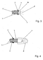
- FIG. 3 shows a schematic section through the lighting unit 2 according to Fig. 1 ,
- the light source 3 in the embodiment, an SMD LED is arranged frontally.
- the contacts / Lötfahnen 4 of the LED 3 protrude up and down slightly beyond the board 6, so that a fillet weld is formed between the contact / Lötfahne 4 and the conductor 7 during soldering.
- Such a connection reliably ensures the contacting of the LED 3 with the conductor 7.
- a solid mechanical connection between the LED 3 and the circuit board 6 is achieved by this connection.
- the contacts / Lötfahnen 4 are mounted on the LED 3, that during assembly of the LED 3 on the front side of the board 6, an air gap 39 is formed between the two components.
- air gaps ensure a clear electrical isolation between the two contacts.
- 39 particularly suitable materials for heat transfer in this air gap may be, for example, thermally conductive pastes or thin metal bands.
- a particularly complex orientation of the LED 3 to the front side of the board 6 is not necessary, since small angular deviations for the emission characteristic of the LED 3 are negligible.
- the boards 6 are usually very precisely cut at an angle of 90 degrees, so that the positioning of an LED 3 can be done only on the slightly protruding contacts / Lötfahen 4.
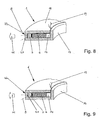
- FIG. 4 Another variant of LEDs 3 is in FIG. 4 displayed.
- a standardized LED 3 instead of an SMD LED, as in the FIGS. 1 to 3 described, a standardized LED 3 used.
- This standardized LED 3 is considerably larger in terms of its width dimension than the LED 3 described above.
- These LEDs 3 also have no soldering lugs 4, but have long wire-shaped contacts 4. to frontal mounting this LED 3 is pushed with the wire-shaped contacts 4 on the board 6 so that the contacts 4 come into contact with the tracks 7 and can be connected to them by means of soldering.
- the resulting solder joints 5 are also made larger by a larger contact area, which also leads to an increased contact area during the soldering process.
- this contacting surface it makes sense in this variant to use, for example, a laser welding method instead of the soldering method.
- This is advantageous since this connection method can be carried out particularly quickly. There are no heating times and / or cooling and positioning times to consider. Also, in this case the thermal load is lower, since far more material of the contacts 4 and a larger volume of material of the LED 3 is available for receiving heat introduced.
- this design requires more space, but is a cost-effective design and particularly suitable when the LEDs 3 of the lighting unit 2 should protrude, for example, during assembly in reflector openings or other openings.
- FIG. 5 shows a plan view of a curved board 6.
- SMD LEDs arranged as a light source 3 on the front side of the board 6.
- electronic components 10 such as resistors or capacitors, are mounted for the operation of the LEDs.
- These electronic components 10 may be designed in conventional standard design or also as SMD components.
- each four LEDs 3 are connected together to form an LED group 17 wherein an electronic component 10 is assigned to each unit.
- an optimal composition with the largest possible life, the lowest power consumption and minimum space requirements can be achieved, with all traces and all components are mounted on or on the board.
- This compilation yields the finished one Lamp unit 2, which only has to be installed in appropriate housing or recordings and electrically connected.
- the lighting unit 2 can follow the contour of the lamp or the installation space.
- a possible use for this could be a lamp in an exterior mirror housing or in a tail light of a motor vehicle.
- FIG. 6 shows a lamp 1, in which the lighting unit 2 is installed in a lamp housing 13.
- This assembly is a completely finished lamp 1 and can be installed or mounted for example in motor vehicles or for other purposes.
- the luminaire housing 12 consists for example of a transparent plastic and is formed substantially U-shaped.
- the distance and the length of the two U-shaped legs 18 of the lamp housing 12 by the thickness of the board 6 and the width of the light source 3 and the width of the board used 6 and the height of the lamps 3 is determined. Since, for example, the board thickness and the LED width are very similar in the case of SMD LEDs, the free space between the two legs 18 can be very narrow.
- a plurality of printed conductors are applied next to one another on the printed circuit board used, which leads to a wide printed circuit board and thus requires longer legs 18.
- the finished illuminant unit 2 is inserted into this free space of the lamp housing 12 and then closed with a rear wall 13 of the housing.
- the rear wall 13 in FIG. 6 substantially corresponds to the width of the lamp housing 12.
- the parting line 15 between the rear wall 13 and the end faces of the legs 18 of the lamp housing 12 is the contact area between the lamp housing 12 and housing rear wall 13, which by means of a suitable bonding method, for example gluing or welding, the two components tightly interconnected.
- a suitable bonding method for example gluing or welding, the two components tightly interconnected.
- the sealing area projects out connection cables 19 or connection contacts 19.
- At least one spring element 14 is provided in the rear region of the luminaire 1 between the circuit board 6 and the rear wall 13 of the housing. This spring element 14 ensures that the lamp unit always bears under pretension on the inner web side of the U-shaped lamp housing 12.
- This spring element may for example consist of a foam or a spring molding of plastic or metal.
- the luminaire housing 12 is translucent for this purpose at the light exit side.
- FIG. 7 represents a further variant of the embodiment of the lamp housing 12 and housing rear wall 13.
- the legs of the U-shaped lamp housing 12 form the front and rear walls.
- On the end faces of the legs of the housing cover 13 is fixed, which is flush with its edges with the outer sides of the front and rear walls of the lamp housing 12.
- the lighting unit 2 is inserted into the lamp housing 12 and in the same manner as in FIG. 6 described closed.
- Such a design of the lamp housing 12 and the housing cover 13 is advantageous if the board 6, for example, strongly S-shaped wound or the course of the board 6 has other undercuts.
- FIGS. 8 and 9 show lights with illuminant units 2, as essentially below FIG. 6 described.
- an outer optic 20 in the region of Lens 22 is mounted, which is provided on the adjacent to the bulbs 3 transverse web of the lamp housing 12.
- This optic 20 serves to focus the emitted light, to collimate or diffuse it, depending on the optical design.
- the attachment of the optics 20 on the outside can be very interesting for design variants. Also, such luminaires can be well integrated into already structured surfaces, so that the luminaires hardly differ from the surrounding area.
- the optics incorporated as an inner optic 21 In the execution after FIG. 9 is the optics incorporated as an inner optic 21.
- the outside of the lens 22 is smooth and flat, which is particularly advantageous if these lamps 1, for example, just with outer surfaces of housings such as vehicles or vehicle components are used.
- This inner optic 21 has the same possible functions as the outer optic 20 according to FIG. 8 , It is advantageous that the inner optic 21 is less susceptible to soiling and / or damage.
- these tightly closed lights 1 can also be used as so-called inserts in molds for the production of, for example, rear lights of vehicles.
- the lights 1 are integrally connected to the entire tail light, the plastic of the tail light enters into a fixed connection with the light 1 or the light 1 encloses at least partially.
- this lamp 1 can also be used as an insert in other devices.
- FIG. 10 shows an exterior rearview mirror 24, consisting of a mirror housing 26, which is composed of an upper mirror housing part 29 and a lower mirror housing part 28.
- the entire mirror housing 26 is pivotally mounted in or against the direction of travel on a mirror base 25.
- the mirror base 25 has a connection surface 27 a form corresponding to the body region of the motor vehicle with corresponding fastening means.
- the luminaire may consist both of a luminous means carrier 2 and of a plurality of illuminant units 2 which lie close to one another.
- Such flat and small-sized lights 1 are particularly well suited in the separation region of two components, as in the embodiment FIG. 10 shown.
- the lamp 1 in the separation region of the upper mirror housing part 29 and the lower mirror housing part 28 is arranged.
- the mirror housing 26 is a Spiegelglasverstellantrieb 32, with which a mirror glass carrier 31 can be adjusted in a known manner. He carries a mirror glass 30. Since the mirror glass 30 and the Spiegelglasverstellantrieb 32 with a mirror support 33 essentially specify the dimensions of the exterior rearview mirror 24 and the requirements for aerodynamic design must also be met, once again shows that a small installation space is of particular interest.
- the lamp 1 has due to the small dimensions only light weight, whereby the weight of the exterior rearview mirror 24 is increased only slightly by the lamp 1. This in turn has the positive consequence that the mirror housing 26 and the mirror support 33 can be made smaller and lighter. Of course, this reduction in installation space and additional weight also translates into significantly lower production costs.
- a Spiegelglasverstellantrieb 32 In the mirror housing 26 is a Spiegelglasverstellantrieb 32, with which a mirror glass carrier 31 can be adjusted in a known manner. He is wearing a mirror glass 30.
- FIG. 12 shows a possible embodiment, as the light 1 can be fixed and fixed independently of the mirror housing 26 in position.
- many mounting options are conceivable, which can even make a diagonally built-in lamp 1 possible.
- FIGS. 8 and 9 shows appropriate optics 20, 21 provided. These optics 20, 21 are required in order to deflect the light rays emerging from the luminaire in the direction of the main emission direction 11.
- lighting fixture is a lamp holder 37 attached as an additional part of the mirror support 33.
- This lamp holder 37 has a light receptacle 36 at its free, projecting into the mirror housing 26 end.
- the lamp 1 is inserted in the installation position in this lamp holder 36 and secured immovably by means of a fastening means, here a clip 38.
- the illustrated clips 38 protrudes through openings of the lamp holder 36 and the lamp 1, wherein the openings in the lamp 1 may be formed as additional eye-shaped or flange-shaped approaches.
- the clips 38 protrude through the lamp, which of course can only be done in one area without affecting the illuminant carrier 2.
- the lamp 1 can also be done on other components, such as other lights or housing parts.
Landscapes
- Engineering & Computer Science (AREA)
- Mechanical Engineering (AREA)
- Non-Portable Lighting Devices Or Systems Thereof (AREA)
- Fastening Of Light Sources Or Lamp Holders (AREA)
- Arrangement Of Elements, Cooling, Sealing, Or The Like Of Lighting Devices (AREA)
Abstract
Description
Die Erfindung betrifft eine Leuchte mit wenigstens einer Leuchtmitteleinheit für Kraftfahrzeuge, nach dem Oberbegriff des Anspruches 1.The invention relates to a luminaire having at least one illuminant unit for motor vehicles, according to the preamble of
Es sind Leuchten mit Leuchtmittelträgern bekannt, bei denen LEDs auf Platinen angeordnet sind. Diese Platinen können über Leiterbahnen auf beiden Seiten der Platine verfügen, wobei das Platinenmaterial in der Regel aus harzgetränkter Pappe, faserverstärkten Harzen und/oder Keramik besteht. Auf den Platinen sind Leiterbahnen vorhanden, die zur Kontaktierung und Positionierung der LEDs dienen. Des weiteren sind oft zusätzlich zu den LEDs weitere elektronische Bauteile auf den Platinen angeordnet.There are lamps with illuminants carriers are known in which LEDs are arranged on boards. These boards may have traces on both sides of the board, where the board material is typically resin impregnated paperboard, fiber reinforced resins and / or ceramics. There are printed circuits on the boards which serve for contacting and positioning the LEDs. Furthermore, additional electronic components are often arranged on the boards in addition to the LEDs.
Die Montage der LEDs auf einer Platine zu einer Leuchtmitteleinheit zur Verwendung in Leuchten ist sehr aufwendig, da die LEDs in eine genaue Einbauposition gebracht werden müssen. Derartige Leuchtmitteleinheiten benötigen in Leuchten einen umfangreichen Einbauraum, der die Leuchten bzw. die verwendeten Gehäuse kompliziert und groß gestaltet. Auch müssen bei gekrümmten Leuchtengehäusen die Platinen in einzelne Segmente aufgeteilt werden, die ihrerseits der Leuchten-/Gehäuseform folgend positioniert werden müssen. Hierzu sind eine Vielzahl von Befestigungs- und Positionierungsmittel notwendig, was die Leuchte/Gehäuse in aller Regel sehr komplex und teuer werden läßt.The mounting of the LEDs on a board to a lighting unit for use in lights is very expensive, since the LEDs must be brought into an exact mounting position. Such lighting units require in luminaires an extensive installation space, which makes the lights and the housing used complicated and large. Also, in curved light housings, the boards must be divided into individual segments, which in turn must be positioned following the light / housing shape. For this purpose, a variety of fastening and positioning means are necessary, which makes the lamp / housing usually very complex and expensive.
Diese konventionellen Leuchten bzw. Leuchtmitteleinheiten sind keine in sich geschlossenen Bauteile und benötigen für eine optisch einwandfreie Funktion weitere Bauteile, die ihrerseits ebenfalls in der Leuchte und/oder dem Gehäuse fixiert und befestigt werden müssen. Die Bezugsgrößen aller Bauteile zueinander sind hierbei von größter Bedeutung, da bereits kleine Abweichungen optisch große Fehler erzeugen. Durch den großen Einbauraum müssen diese Leuchten bzw. Gehäuse entsprechend der weiteren einzubauenden Elemente entsprechend groß gestaltet werden. Der hierauf begründete Mehraufwand hat ein erhöhtes Gewicht wie auch einen größeren Materialeinsatz zur Folge und führt unter Berücksichtigung des höheren Montageaufwandes zu einer nicht unerheblichen Verteuerung der kompletten Baueinheit. Weiter sind durch diese Rahmenbedingungen die gestalterischen Möglichkeiten stark eingeschränkt bzw. können hierzu besondere Ausgestaltungen nur durch einen extrem hohen konstruktiven und fertigungstechnischen Aufwand gelöst werden.These conventional luminaires or illuminant units are not self-contained components and require further components for optically perfect functioning, which in turn likewise have to be fixed and fastened in the luminaire and / or the housing. The reference values of all components to each other here are of utmost importance, since even small deviations produce visually large errors. Due to the large installation space these lights or housing must be designed to be large according to the other elements to be incorporated. The additional expenditure based on this results in an increased weight as well as a greater use of materials and leads, taking into account the higher assembly costs, to a not inconsiderable increase in the cost of the complete structural unit. Next, the design options are severely limited by this framework conditions or special designs can be solved only by an extremely high design and manufacturing effort.
Aus
Der Erfindung liegt die Aufgabe zugrunde, die gattungsgemäße Leuchte mit Leuchtmitteleinheit so auszubilden, daß eine besonders kompakte, flache und leicht zu montierende Leuchte bei beliebiger Formgebung und geringster Anzahl von Teilen einfach und kostengünstig herzustellen ist.The invention has the object of providing the generic lamp with illuminant unit in such a way that a particularly compact, flat and easy to install light with any shape and smallest number of parts is simple and inexpensive to manufacture.
Diese Aufgabe wird bei der gattungsgemäßen Leuchte mit Leuchtmitteleinheit erfindungsgemäß mit den kennzeichnenden Merkmalen des Anspruches 1 gelöst.This object is achieved in the generic lamp with illuminant unit according to the invention with the characterizing features of
Bei der erfindungsgemäßen Leuchte wird besonderer Wert auf eine sehr flach bauende Leuchte bei beliebiger Formgebung der Platine gelegt. Hierbei ist die Leuchtmitteleinheit so gestaltet, daß die Schmalseite der Platine in die Hauptabstrahlrichtung der Leuchte weist. Die Leuchtmittel sind im wesentlichen entlang der Schmalseite der Platine angeordnet und mit den Leiterbahnen der Platine verbunden, was zu einer besonders flach bauenden Leuchtmitteleinheit führt. Derartig flach bauende Leuchtmitteleinheiten können in sehr kleine und flache Leuchtengehäuse eingebracht werden, was wiederum zu einem sehr flachen und einfachen Bauteil führt. Die Leuchtmitteleinheit wird beispielsweise mit standardisierten LEDs als Leuchtmittel bestückt, wobei anders als bei einer flächigen Positionierung der LEDs nicht mit besonderen Schwierigkeiten bei der Montage zu rechnen ist. Die Schmal- bzw. Stirnseite der Platine ist leicht zugänglich und kann sehr präzise gefräst, geschnitten oder gestanzt werden. Da keine weiteren optischen Bauteile in verhältnismäßig großen Distanzen zueinander sehr präzise positioniert werden müssen, ist eine minimale Montageabweichung von weit aus geringerer Auswirkung als bei handelsüblichen Leuchtenausführungen. Der Montageaufwand ist stark reduziert und läßt sich im Vergleich zu üblichen Ausführungen einfach und schnell durchführen.In the lamp according to the invention particular importance is placed on a very flat-fitting light with any shape of the board. Here, the lighting unit is designed so that the narrow side of the board has in the main emission of the lamp. The lighting means are arranged substantially along the narrow side of the board and connected to the tracks of the board, resulting in a particularly flat-building Lamp unit leads. Such flat-building lighting units can be placed in very small and flat luminaire housing, which in turn leads to a very flat and simple component. The lighting unit is equipped, for example, with standardized LEDs as a light source, unlike a planar positioning of the LEDs is not expected to particular difficulties during installation. The narrow or front side of the board is easily accessible and can be precisely milled, cut or punched. Since no further optical components have to be positioned very precisely in relatively large distances from one another, a minimal assembly deviation is far less of an effect than with commercially available lamp designs. The assembly effort is greatly reduced and can be performed easily and quickly compared to conventional designs.
Solche gefertigten Leuchten weisen durch die Verwendung der Halbleiterbauelemente in der Regel eine Haltbarkeit über die gesamte Lebensdauer auf. Ferner können diese Leuchten als Einlegeteil beispielsweise in eine Spritzgußform eingebracht werden. Zum Beispiel kann bei einer Fahrzeugheckleuchte der Kunststoff der gesamten Heckleuchte oder eines Gehäuses beim Spritzvorgang durch eine entsprechende Vernetzung oder durch wenigstens bereichsweises Umfließen der Leuchte diese in eine komplette Baueinheit integrieren.As a rule, such manufactured luminaires have a durability over the entire service life due to the use of the semiconductor components. Furthermore, these lights can be introduced as an insert, for example, in an injection mold. For example, in the case of a vehicle tail lamp, the plastic of the entire taillight or of a housing can be integrated into a complete structural unit during the injection process by means of a corresponding cross-linking or at least partially circumscribing the luminaire.
Die Kombination mehrerer Leuchtmitteleinheiten zu einer größeren Baugruppe ist im Vergleich zu den derzeit gebräuchlichen Leuchten stark gewichtsreduziert und benötigt erheblich weniger Bauraum. Für Leuchten, beispielsweise in Außenrückblickspiegeln, bedeutet dieser Umstand eine erhebliche Verbesserung, da außer einer Bauraum- und Gewichtseinsparung die thermische Einbringung wie auch die Möglichkeit der Schwingungsanregung der gesamten Leuchte erheblich reduziert ist. Schließlich ermöglicht diese Leuchtenausführung Designlösungen, die sich mit heutiger Technik nicht realisieren lassen.The combination of several lighting units to a larger assembly is greatly reduced in weight compared to the currently used lights and requires considerably less space. For lights, for example, in exterior rearview mirrors, this circumstance represents a significant improvement, since in addition to a space and weight saving, the thermal input as well as the possibility of vibration excitation of the entire light is significantly reduced. Finally, this luminaire design enables design solutions that can not be realized with today's technology.
Weiter bietet dieses Konzept eine vereinfachte Montage und Anbringung in Gehäusen oder sonstigen Vorrichtungen. So sind durch den kleineren Bauraum und die besonders flache Bauweise aerodynamisch günstigere Ausführungen der Leuchten/Gehäuse möglich, bzw. können diese Leuchten in der Trennungsebene von Gehäusen so angeordnet werden, daß diese Leuchten kaum auffallen und somit keine störenden Einflüsse auf die gesamte Designgestaltung nehmen können.Furthermore, this concept offers a simplified mounting and mounting in housings or other devices. So aerodynamically favorable versions of the lights / housing are possible through the smaller space and the particularly flat design, or these lights can be arranged in the plane of separation of housings so that these lights barely noticeable and thus can take no disturbing influences on the entire design ,
Die Befestigung dieser Leuchten erfolgt durch eine Verschraubung oder eine Clipsverbindung an weiteren Bauteilen, wie zum Beispiel eines Gehäuses oder an bereits vorhandenen Haltern.The attachment of these lights is done by a screw or a clip connection to other components, such as a housing or on existing holders.
Weitere Merkmale der Erfindung ergeben sich aus den weiteren Ansprüchen, der Beschreibung und den Zeichnungen.Further features of the invention will become apparent from the other claims, the description and the drawings.
Die Erfindung wird anhand einiger in den Zeichnungen dargestellter Ausführungsformen näher erläutert. Es zeigt:
- Fig. 1
- eine Leuchtmitteleinheit mit an der Stirnseite einer Platine angeordneten Leuchtmitteln,
- Fig. 2
- zwei zu einem Block verbundene Leuchtmitteleinheiten,
- Fig. 3
- in schematischer Darstellung einen Schnitt durch die Leuchtmitteleinheit gemäß
Fig. 1 unter Verwendung einer SMD-LED, - Fig. 4
- in schematischer Darstellung einen Schnitt durch die Leuchtmitteleinheit gemäß
Fig. 1 unter Verwendung einer LED in Standardbauweise, - Fig. 5
- eine Leuchtmitteleinheit mit an der Stirnseite angeordneten Leuchtmitteln entlang einer gekrümmten Platine,
- Fig. 6 bis Fig. 9
- jeweils verschiedene Ausführungsformen von Leuchtmitteleinheiten in Leuchtengehäusen,
- Fig. 10
- einen Außenrückblickspiegel mit eingesetzter Leuchte gemäß den
Figuren 6 bis 9 - Fig. 11
- eine Schnittdarstellung durch den Außenrückblickspiegel gemäß
Figur 10 - Fig. 12
- eine schematische Schnittdarstellung durch den Außenrückblickspiegel gemäß
Figur 10
- Fig. 1
- a light-emitting unit with bulbs arranged on the front side of a circuit board,
- Fig. 2
- two lamp units connected in a block,
- Fig. 3
- in a schematic representation of a section through the lighting unit according to
Fig. 1 using an SMD LED, - Fig. 4
- in a schematic representation of a section through the lighting unit according to
Fig. 1 using a standard LED, - Fig. 5
- a light-emitting unit with lamps arranged on the front side along a curved circuit board,
- FIG. 6 to FIG. 9
- different embodiments of illuminant units in luminaire housings,
- Fig. 10
- an exterior rearview mirror with inserted light according to the
FIGS. 6 to 9 . - Fig. 11
- a sectional view through the exterior rearview mirror according to
FIG. 10 . - Fig. 12
- a schematic sectional view through the exterior rearview mirror according to
FIG. 10 with fasteners for fixing the lamp in the exterior rearview mirror.
In
Die Leuchtmittel 3 sind stirnseitig an der Platine 6 angeordnet, wobei sich jeweils ein Kontakt/Lötfahne 4 des Leuchtmittels 3 mit einer geringen Spaltbildung in unmittelbarer Nachbarschaft einer Leiterbahnverbindung 7 befindet. Diese Kontakte 4 werden vorzugsweise durch Weichlöten mit den Leiterbahnverbindungen 7 verbunden, sodaß der bestehende Spalt zwischen den Kontakten 4 und den Leiterbahnverbindungen 7 sicher überbrückt wird. Wird nun an den Leiterbahnen 7 auf der Ober- und Unterseite der Platine 6 Spannung angelegt, kann über die Lötverbindungen der Leiterbahnen 7 und der Kontakte ein Strom fließen, der die Leuchtmittel entsprechend leuchten lassen kann.The
Um eine besonders flach bauende Leuchtmitteleinheit 2 bauen zu können, empfiehlt es sich, wie in diesem Ausführungsbeispiel dargestellt, als Leuchtmittel 3 SMD-LEDs zu verwenden. Bei SMD-LEDs (Surface Mounted Devices - Light Emitting Diodes) handelt es sich um oberflächen-montierbare Bauteile in extrem kleiner Bauform. Durch die Verwendung derartiger Bauteile, die im wesentlichen nicht oder nur gering über die Dicke der Platine 6 herausragen, wird es möglich, sehr flache und strichförmige/bandförmige Leuchten herzustellen. Die in
Eine Leuchtmitteleinheit 2 kann mit weiteren Leuchtmitteleinheiten 2 durch paralleles Aneinanderreihen zu einem Leuchtmittelblock kombiniert werden. Hierbei werden, wie in
Die zu einem Block verbundenen Leuchtmitteleinheiten 2 besitzen wie eine einzelne Leuchtmitteleinheit 2 jeweils nur zwei Anschlußkontaktstellen 16, von der sich jeweils eine Kontaktstelle 16 auf der Oberseite der oberen Platine 6 beziehungsweise auf der Unterseite der unteren Platine 6 befindet. Um unerwünschte Kontaktbildungen der im Block eng benachbarten Leuchtmitteleinheiten zu verhindern, können die Platinen 6 mit einem Schutzlack oder einem sonstigen isolierenden Material beschichtet sein.The light-emitting
Die Kontakte/Lötfahnen 4 sind so an der LED 3 angebracht, daß bei der Montage der LED 3 an der Stirnseite der Platine 6 ein Luftspalt 39 zwischen beiden Bauteilen entsteht. Derartige Luftspalte sichern eine eindeutige galvanische Trennung zwischen beiden Kontakten. Weiterhin ist es möglich, in diesem Luftspalt 39 besonders geeignete Materialien zur Wärmeübertragung einzufügen. Dies können beispielsweise wärmeleitende Pasten oder dünne Metallbänder sein.The contacts /
Eine besonders aufwendige Ausrichtung der LED 3 zur Stirnseite der Platine 6 ist nicht notwendig, da geringe Winkelabweichungen für die Abstrahlcharakteristik der LED 3 unwesentlich sind. Die Platinen 6 werden in der Regel sehr präzise unter einem Winkel von 90 Grad geschnitten, sodaß die Positionierung einer LED 3 ausschließlich über die leicht hervorstehenden Kontakte/Lötfahnen 4 erfolgen kann.A particularly complex orientation of the
Eine weitere Variante von LEDs 3 ist in
In
Durch die Krümmung der Platine 6 kann die Leuchtmitteleinheit 2 der Kontur der Leuchte bzw. des Einbauraumes folgen. Ein hierfür möglicher Einsatz könnte eine Leuchte in einem Außenspiegelgehäuse oder in einer Rückleuchte eines Kraftfahrzeugs sein.Due to the curvature of the
Das Ausführungsbeispiel gemäß
Das Leuchtengehäuse 12 besteht zum Beispiel aus einem transparenten Kunststoff und ist im wesentlichen U-förmig ausgebildet. Hierbei wird der Abstand und die Länge der beiden U-förmigen Schenkel 18 des Leuchtengehäuses 12 durch die Dicke der Platine 6 bzw. der Breite der Leuchtmittel 3 und der Breite der verwendeten Platine 6 sowie der Höhe der Leuchtmittel 3 bestimmt. Da beispielsweise bei SMD-LEDs die Platinendicke und die LED-Breite sehr ähnlich sind, kann der Freiraum zwischen den beiden Schenkeln 18 sehr schmal ausfallen. In der Regel sind auf der verwendeten Platine mehrere Leiterbahnen nebeneinander aufgebracht, was zu einer breiten Platine führt und somit längere Schenkel 18 erfordert. Die fertige Leuchtmitteleinheit 2 wird in diesen Freiraum des Leuchtengehäuses 12 eingeschoben und anschließend mit einer Gehäuserückwand 13 verschlossen. Die Gehäuserückwand 13 in
Damit die Leuchtmitteleinheit 2 im geschlossenen Leuchtengehäuse nicht klappern kann und immer in einer vorbestimmten Position gehalten wird, ist im rückseitigen Bereich der Leuchte 1 zwischen der Platine 6 und der Gehäuserückwand 13 wenigstens ein Federelement 14 vorgesehen. Dieses Federelement 14 gewährleistet, daß die Leuchtmitteleinheit stets unter Vorspannung an der Innenstegseite des U-förmigen Leuchtengehäuses 12 anliegt. Dieses Federelement kann beispielsweise aus einem Schaumstoff oder einem Federformelement aus Kunststoff oder Metall bestehen.So that the
Eine Lackierung oder sonstige Lichtabschottung zur Verhinderung von seitlich aus der Leuchte austretendem Licht ist hier nicht erforderlich, da das gesamte abstrahlende Licht im Wesentlichen in die Hauptabstrahlrichtung 11 abgestrahlt wird. Das Leuchtengehäuse 12 ist zu diesem Zweck an der Lichtaustrittsseite lichtdurchlässig.A painting or other Lichtabschottung to prevent light emerging from the side of the light is not required here, since the entire emitting light is radiated substantially in the
Die
Bei der Ausführung nach
Wie bei in den
Die
In der Trennfuge zwischen dem oberen Spiegelgehäuseteil 29 und dem unteren Spiegelgehäuseteil 28 ist eine Leuchte 1 eingebaut. Hierbei kann die Leuchte sowohl aus einem Leuchtmittelträger 2 wie auch aus mehreren dicht aneinander liegenden Leuchtmitteleinheiten 2 bestehen. Derartigen flach und klein bauende Leuchten 1 sind besonders gut im Trennbereich zweier Bauteile geeignet, wie im Ausführungsbeispiel
Auch sind Kombinationen mit weiteren anderen Leuchten, zum Beispiel Ausstiegsleuchten, Positionsleuchten oder Tagfahrscheinwerfern möglich, wobei durch den benötigten Einbauraum der weiteren Leuchten oder Bauteile wiederum die kleine und besonders flach bauende Ausführungsform dieser Leuchten 1 zum Tragen kommt.Also combinations with other other lights, such as exit lights, position lights or daytime running lights are possible, in turn, comes through the required installation space of the other lights or components in turn, the small and very flat design embodiment of these
Dies ist besonders gut in der Schnittdarstellung der
Im Spiegelgehäuse 26 befindet sich ein Spiegelglasverstellantrieb 32, mit dem ein Spiegelglasträger 31 in bekannter Weise verstellt werden kann. Er trägt ein Spiegelglas 30.In the
Bei der in
Claims (15)
- A lamp (1) with at least one illumination device (2) for motor vehicles, comprising at least one circuit board (6) and at least one illuminant (3), attached to the circuit board, wherein the illuminant is connected to conductive paths (7) of the circuit board (6) through contacts (4), wherein the illuminant (3) is positioned at a narrow side of the circuit board (6), wherein the illumination device (2) is disposed in a housing which includes a light permeable light exit side, wherein the illumination device (2) contacts the light permeable light exit side of the housing with a preload.
- The lamp according to claim 1, wherein the housing comprises a base component (12) with a U-shaped cross section, wherein the open side of the base component is closed tight through a housing wall (13).
- The lamp according to claim 1 or 2, wherein the housing comprises external optics (20) in a light exit portion at an outside of the housing and/or comprises internal optics (21) at an inside of the housing.
- The lamp according to one of the claims 1 through 3, wherein the illuminant (3) comprises optics on its light exit side.
- The lamp according to one of the claims 1 through 4, wherein at least one spring element (14) is provided for generating the preload in the housing.
- The lamp according to claim 5, wherein the spring element (14) is provided at the side facing away from the illuminant (3) between the circuit board (6) and a rear wall of the housing (13).
- The lamp according to claim 5 or 6, wherein the spring element (14) is comprised of a foam material.
- The lamp according to claim 5 or 6, wherein the spring element (14) is configured as a formed spring element.
- The lamp according to one of the claims 1 through 8, wherein the conductive paths (7) are disposed on a top side and/or on a bottom side of the circuit board.
- The lamp according to one of the claims 1 through 9, wherein the illuminant (3) is attached to the contact (4) at conductive paths (7) on the top side or on the bottom side of the circuit board (6) advantageously configured with a cambered shape.
- The lamp according to one of the claims 1 through 10, wherein the contacts' (4) contact the top side and/or the bottom side of the circuit board (6) in a flat configuration in the portion of the conductive paths (7).
- The lamp according to one of the claims 1 through 11, wherein the illuminants (3) are LEDs which are inserted into recesses in the face of the circuit board (6).
- A method for using the lamp according to one of the claims 1 through 12 in an exterior rearview mirror (24) of a motor vehicle.
- An exterior rearview mirror (24) for a motor vehicle, comprising:a mirror housing (26), assembled from an upper mirror housing component (29) and a lower mirror housing component (28), whereinthe lamp (1) according to one of the claims 1 through 12 is disposed in a separation gap between the two mirror housing components (28, 29).
- The exterior rearview mirror according to claim 14, wherein a lamp holder (37) is disposed at a mirror support (33), wherein the lamp holder includes a lamp receiver (36) at its end protruding into the mirror housing (26), wherein the lamp (1) is supported in the lamp holder.
Applications Claiming Priority (1)
| Application Number | Priority Date | Filing Date | Title |
|---|---|---|---|
| DE102006021973A DE102006021973A1 (en) | 2006-05-03 | 2006-05-03 | Luminaire with at least one lighting unit for vehicles, preferably for motor vehicles |
Publications (2)
| Publication Number | Publication Date |
|---|---|
| EP1852306A1 EP1852306A1 (en) | 2007-11-07 |
| EP1852306B1 true EP1852306B1 (en) | 2010-12-01 |
Family
ID=38235144
Family Applications (1)
| Application Number | Title | Priority Date | Filing Date |
|---|---|---|---|
| EP07007657A Active EP1852306B1 (en) | 2006-05-03 | 2007-04-14 | Lamp with at least one illumination device for vehicles, preferably for motor vehicle |
Country Status (4)
| Country | Link |
|---|---|
| US (1) | US8029177B2 (en) |
| EP (1) | EP1852306B1 (en) |
| AT (1) | ATE490121T1 (en) |
| DE (2) | DE102006021973A1 (en) |
Cited By (1)
| Publication number | Priority date | Publication date | Assignee | Title |
|---|---|---|---|---|
| EP3061587A1 (en) | 2015-02-24 | 2016-08-31 | SMR Patents S.à.r.l. | Method for producing a light for vehicles and external mirror assembly of a vehicle with a light produced in such a way |
Families Citing this family (9)
| Publication number | Priority date | Publication date | Assignee | Title |
|---|---|---|---|---|
| DE202008007474U1 (en) | 2008-05-30 | 2008-08-07 | Jom Car Parts & Car Hifi Gmbh | Luminous band with a flexurally elastic strip-shaped carrier |
| DE102010003073B4 (en) | 2010-03-19 | 2013-12-19 | Osram Gmbh | LED lighting device |
| EP2377720B1 (en) * | 2010-04-19 | 2015-06-10 | SMR Patents S.à.r.l. | Light guide device for automotive use |
| US20120020099A1 (en) * | 2010-06-22 | 2012-01-26 | Rob Bingle | Side-view mirror assembly with selectively illuminating portion |
| CN103988018B (en) * | 2011-07-27 | 2017-07-07 | 格罗特工业有限公司 | For the method and system of the Flexible Lighting Equipment with the edge light device using the photolytic activity sheet material with integrated light-emitting diode |
| TW201341717A (en) * | 2012-04-09 | 2013-10-16 | Foxsemicon Integrated Tech Inc | Lamp cover |
| US9200785B2 (en) * | 2013-08-09 | 2015-12-01 | Kevin Yang | LED light having edge mounted LED's |
| US10041657B2 (en) * | 2016-06-13 | 2018-08-07 | Rebo Lighting & Electronics, Llc | Clip unit and edge mounted light emitting diode (LED) assembly comprising a clip unit |
| DE202019100126U1 (en) * | 2019-01-11 | 2020-04-15 | Zumtobel Lighting Gmbh | Luminaire arrangement for an elongated luminaire |
Family Cites Families (17)
| Publication number | Priority date | Publication date | Assignee | Title |
|---|---|---|---|---|
| US4597033A (en) * | 1983-05-17 | 1986-06-24 | Gulf & Western Manufacturing Co. | Flexible elongated lighting system |
| FR2707223B1 (en) * | 1993-07-07 | 1995-09-29 | Valeo Vision | Improved signaling light with light-emitting diodes. |
| US5561414A (en) * | 1995-02-22 | 1996-10-01 | Yu Hsiang Chiu Enterprise Co., Ltd. | Bicycle warning signal control device |
| JP3260593B2 (en) * | 1995-06-09 | 2002-02-25 | 株式会社小糸製作所 | Car signal lights |
| US6203191B1 (en) * | 1998-10-28 | 2001-03-20 | Speculative Incorporated | Method of junction temperature determination and control utilizing heat flow |
| DE10020099A1 (en) * | 2000-04-22 | 2001-10-25 | Hella Kg Hueck & Co | Motor vehicle light comprises semiconductor structural elements whose main radiation direction runs in PCB plane or parallel to it |
| ES2168071B1 (en) * | 2000-07-12 | 2003-07-16 | Barros Alejandro Rodriguez | MODULAR REAR VIEW MIRROR WITH INTERCHANGEABLE MULTIPLE SIGNALS FOR VEHICLES OF 2, 3, 4 OR MORE WHEELS. |
| ES2288162T3 (en) * | 2000-12-21 | 2008-01-01 | Gamesman Limited | LAMPS. |
| US6472823B2 (en) * | 2001-03-07 | 2002-10-29 | Star Reach Corporation | LED tubular lighting device and control device |
| EP1381810A1 (en) * | 2001-03-21 | 2004-01-21 | Supervision International, Inc. | Flexible circuit board with led lighting |
| JP3660267B2 (en) * | 2001-04-13 | 2005-06-15 | 株式会社テーアンテー | Lighting fixture |
| US6578986B2 (en) * | 2001-06-29 | 2003-06-17 | Permlight Products, Inc. | Modular mounting arrangement and method for light emitting diodes |
| US6578984B2 (en) * | 2001-09-26 | 2003-06-17 | Lite-On Electronics, Inc. | Circuit board indicator |
| US6902308B2 (en) * | 2001-10-09 | 2005-06-07 | Rosstech Signals, Inc. | Illumination system |
| US20050052128A1 (en) * | 2003-09-08 | 2005-03-10 | Polymatech Co. Ltd. | Light emitting electronic component |
| DE102004020493B4 (en) * | 2004-04-26 | 2012-07-12 | Odelo Gmbh | Light distribution assembly with a variety of modules |
| US20060268565A1 (en) * | 2005-05-25 | 2006-11-30 | Haoli Precision Industrial Co., Ltd. | Led lighting device with light diffusing effect |
-
2006
- 2006-05-03 DE DE102006021973A patent/DE102006021973A1/en not_active Withdrawn
-
2007
- 2007-04-14 DE DE502007005813T patent/DE502007005813D1/en active Active
- 2007-04-14 EP EP07007657A patent/EP1852306B1/en active Active
- 2007-04-14 AT AT07007657T patent/ATE490121T1/en active
- 2007-05-01 US US11/742,824 patent/US8029177B2/en active Active
Cited By (1)
| Publication number | Priority date | Publication date | Assignee | Title |
|---|---|---|---|---|
| EP3061587A1 (en) | 2015-02-24 | 2016-08-31 | SMR Patents S.à.r.l. | Method for producing a light for vehicles and external mirror assembly of a vehicle with a light produced in such a way |
Also Published As
| Publication number | Publication date |
|---|---|
| US20070258253A1 (en) | 2007-11-08 |
| EP1852306A1 (en) | 2007-11-07 |
| ATE490121T1 (en) | 2010-12-15 |
| US8029177B2 (en) | 2011-10-04 |
| DE102006021973A1 (en) | 2007-11-15 |
| DE502007005813D1 (en) | 2011-01-13 |
Similar Documents
| Publication | Publication Date | Title |
|---|---|---|
| EP1852306B1 (en) | Lamp with at least one illumination device for vehicles, preferably for motor vehicle | |
| EP2095016B1 (en) | Illumination unit for vehicle headlights, and vehicle headlight | |
| EP2291594B1 (en) | Lighting unit for vehicle headlights and vehicle headlight | |
| EP2317213B1 (en) | Light diode module of a motor vehicle lighting device and motor vehicle lighting device | |
| EP1970250B1 (en) | Lamp for vehicles, in particular motor vehicles | |
| EP2783155B1 (en) | Lighting device for a motor vehicle | |
| EP2428724A1 (en) | Optimal light coupling for rear view devices | |
| EP1655174A2 (en) | Vehicular lighting device | |
| EP1099601B1 (en) | Vehicle light | |
| AT516638A1 (en) | Method for producing a circuit carrier and circuit carrier | |
| DE102009023268A1 (en) | LED lighting unit for halogen reflector lamp, has reflector base provided with number of recesses, and reflector arranged on carrier plate, where carrier plate and reflector are held together by fastening unit | |
| DE102005012104A1 (en) | Housing, in particular mirror housing | |
| DE102006051542B4 (en) | LED signal headlights, in particular for rail vehicles, and LED holders for such a headlight | |
| EP2131101A1 (en) | Lamp | |
| EP1977159B1 (en) | Luminaire | |
| WO2020229344A1 (en) | Vehicle component, vehicle and method | |
| DE10160052A1 (en) | Vehicle light has light elements on periphery of bearer part arranged to radiate radially outwards and with laterally arranged contact feet that make flat contact with contact surfaces | |
| DE10116957A1 (en) | vehicle light | |
| DE102008004483B4 (en) | Vehicle lamp with flexible lamp assembly | |
| EP2357395B1 (en) | Light unit with light guide | |
| EP3409439B1 (en) | Optical device, lighting assembly, headlamp and method | |
| DE102009024614A1 (en) | Method for manufacturing lighting device for vehicle, involves providing illumination device with semiconductor light source for generating light and separate optical component for distribution of light | |
| EP0833761B1 (en) | Interior light, in particular a vehicle courtesy light | |
| DE20314664U1 (en) | Signaling lamp for road vehicle, incorporates array of LED's with curved top surfaces fitting into lenses which refract light rays to form beams with small angle of divergence | |
| DE202011100723U1 (en) | lamp |
Legal Events
| Date | Code | Title | Description |
|---|---|---|---|
| PUAI | Public reference made under article 153(3) epc to a published international application that has entered the european phase |
Free format text: ORIGINAL CODE: 0009012 |
|
| AK | Designated contracting states |
Kind code of ref document: A1 Designated state(s): AT BE BG CH CY CZ DE DK EE ES FI FR GB GR HU IE IS IT LI LT LU LV MC MT NL PL PT RO SE SI SK TR |
|
| AX | Request for extension of the european patent |
Extension state: AL BA HR MK YU |
|
| RAP1 | Party data changed (applicant data changed or rights of an application transferred) |
Owner name: VISIOCORP PATENTS S.A.R.L. |
|
| 17P | Request for examination filed |
Effective date: 20080416 |
|
| 17Q | First examination report despatched |
Effective date: 20080520 |
|
| AKX | Designation fees paid |
Designated state(s): AT BE BG CH CY CZ DE DK EE ES FI FR GB GR HU IE IS IT LI LT LU LV MC MT NL PL PT RO SE SI SK TR |
|
| 111Z | Information provided on other rights and legal means of execution |
Free format text: AT BE BG CH CY CZ DE DK EE ES FI FR GB GR HU IE IS IT LT LU LV MC MT NL PL PT RO SE SI SK TR Effective date: 20080208 |
|
| RAP1 | Party data changed (applicant data changed or rights of an application transferred) |
Owner name: VISIOCORP PATENTS S.A.R.L. |
|
| RAP1 | Party data changed (applicant data changed or rights of an application transferred) |
Owner name: SMR PATENTS S.A.R.L. |
|
| GRAP | Despatch of communication of intention to grant a patent |
Free format text: ORIGINAL CODE: EPIDOSNIGR1 |
|
| GRAS | Grant fee paid |
Free format text: ORIGINAL CODE: EPIDOSNIGR3 |
|
| GRAA | (expected) grant |
Free format text: ORIGINAL CODE: 0009210 |
|
| AK | Designated contracting states |
Kind code of ref document: B1 Designated state(s): AT BE BG CH CY CZ DE DK EE ES FI FR GB GR HU IE IS IT LI LT LU LV MC MT NL PL PT RO SE SI SK TR |
|
| REG | Reference to a national code |
Ref country code: GB Ref legal event code: FG4D Free format text: NOT ENGLISH |
|
| REG | Reference to a national code |
Ref country code: CH Ref legal event code: EP |
|
| REG | Reference to a national code |
Ref country code: IE Ref legal event code: FG4D |
|
| REF | Corresponds to: |
Ref document number: 502007005813 Country of ref document: DE Date of ref document: 20110113 Kind code of ref document: P |
|
| REG | Reference to a national code |
Ref country code: NL Ref legal event code: VDEP Effective date: 20101201 |
|
| PG25 | Lapsed in a contracting state [announced via postgrant information from national office to epo] |
Ref country code: LT Free format text: LAPSE BECAUSE OF FAILURE TO SUBMIT A TRANSLATION OF THE DESCRIPTION OR TO PAY THE FEE WITHIN THE PRESCRIBED TIME-LIMIT Effective date: 20101201 |
|
| LTIE | Lt: invalidation of european patent or patent extension |
Effective date: 20101201 |
|
| PG25 | Lapsed in a contracting state [announced via postgrant information from national office to epo] |
Ref country code: SE Free format text: LAPSE BECAUSE OF FAILURE TO SUBMIT A TRANSLATION OF THE DESCRIPTION OR TO PAY THE FEE WITHIN THE PRESCRIBED TIME-LIMIT Effective date: 20101201 Ref country code: SI Free format text: LAPSE BECAUSE OF FAILURE TO SUBMIT A TRANSLATION OF THE DESCRIPTION OR TO PAY THE FEE WITHIN THE PRESCRIBED TIME-LIMIT Effective date: 20101201 Ref country code: CY Free format text: LAPSE BECAUSE OF FAILURE TO SUBMIT A TRANSLATION OF THE DESCRIPTION OR TO PAY THE FEE WITHIN THE PRESCRIBED TIME-LIMIT Effective date: 20101201 Ref country code: LV Free format text: LAPSE BECAUSE OF FAILURE TO SUBMIT A TRANSLATION OF THE DESCRIPTION OR TO PAY THE FEE WITHIN THE PRESCRIBED TIME-LIMIT Effective date: 20101201 Ref country code: BG Free format text: LAPSE BECAUSE OF FAILURE TO SUBMIT A TRANSLATION OF THE DESCRIPTION OR TO PAY THE FEE WITHIN THE PRESCRIBED TIME-LIMIT Effective date: 20110301 Ref country code: FI Free format text: LAPSE BECAUSE OF FAILURE TO SUBMIT A TRANSLATION OF THE DESCRIPTION OR TO PAY THE FEE WITHIN THE PRESCRIBED TIME-LIMIT Effective date: 20101201 Ref country code: NL Free format text: LAPSE BECAUSE OF FAILURE TO SUBMIT A TRANSLATION OF THE DESCRIPTION OR TO PAY THE FEE WITHIN THE PRESCRIBED TIME-LIMIT Effective date: 20101201 |
|
| REG | Reference to a national code |
Ref country code: IE Ref legal event code: FD4D |
|
| PG25 | Lapsed in a contracting state [announced via postgrant information from national office to epo] |
Ref country code: GR Free format text: LAPSE BECAUSE OF FAILURE TO SUBMIT A TRANSLATION OF THE DESCRIPTION OR TO PAY THE FEE WITHIN THE PRESCRIBED TIME-LIMIT Effective date: 20110302 |
|
| PG25 | Lapsed in a contracting state [announced via postgrant information from national office to epo] |
Ref country code: ES Free format text: LAPSE BECAUSE OF FAILURE TO SUBMIT A TRANSLATION OF THE DESCRIPTION OR TO PAY THE FEE WITHIN THE PRESCRIBED TIME-LIMIT Effective date: 20110312 Ref country code: PT Free format text: LAPSE BECAUSE OF FAILURE TO SUBMIT A TRANSLATION OF THE DESCRIPTION OR TO PAY THE FEE WITHIN THE PRESCRIBED TIME-LIMIT Effective date: 20110401 Ref country code: IS Free format text: LAPSE BECAUSE OF FAILURE TO SUBMIT A TRANSLATION OF THE DESCRIPTION OR TO PAY THE FEE WITHIN THE PRESCRIBED TIME-LIMIT Effective date: 20110401 Ref country code: CZ Free format text: LAPSE BECAUSE OF FAILURE TO SUBMIT A TRANSLATION OF THE DESCRIPTION OR TO PAY THE FEE WITHIN THE PRESCRIBED TIME-LIMIT Effective date: 20101201 Ref country code: EE Free format text: LAPSE BECAUSE OF FAILURE TO SUBMIT A TRANSLATION OF THE DESCRIPTION OR TO PAY THE FEE WITHIN THE PRESCRIBED TIME-LIMIT Effective date: 20101201 Ref country code: IE Free format text: LAPSE BECAUSE OF FAILURE TO SUBMIT A TRANSLATION OF THE DESCRIPTION OR TO PAY THE FEE WITHIN THE PRESCRIBED TIME-LIMIT Effective date: 20101201 |
|
| PG25 | Lapsed in a contracting state [announced via postgrant information from national office to epo] |
Ref country code: RO Free format text: LAPSE BECAUSE OF FAILURE TO SUBMIT A TRANSLATION OF THE DESCRIPTION OR TO PAY THE FEE WITHIN THE PRESCRIBED TIME-LIMIT Effective date: 20101201 Ref country code: PL Free format text: LAPSE BECAUSE OF FAILURE TO SUBMIT A TRANSLATION OF THE DESCRIPTION OR TO PAY THE FEE WITHIN THE PRESCRIBED TIME-LIMIT Effective date: 20101201 Ref country code: SK Free format text: LAPSE BECAUSE OF FAILURE TO SUBMIT A TRANSLATION OF THE DESCRIPTION OR TO PAY THE FEE WITHIN THE PRESCRIBED TIME-LIMIT Effective date: 20101201 |
|
| PLBE | No opposition filed within time limit |
Free format text: ORIGINAL CODE: 0009261 |
|
| STAA | Information on the status of an ep patent application or granted ep patent |
Free format text: STATUS: NO OPPOSITION FILED WITHIN TIME LIMIT |
|
| BERE | Be: lapsed |
Owner name: SMR PATENTS S.A.R.L. Effective date: 20110430 |
|
| PG25 | Lapsed in a contracting state [announced via postgrant information from national office to epo] |
Ref country code: DK Free format text: LAPSE BECAUSE OF FAILURE TO SUBMIT A TRANSLATION OF THE DESCRIPTION OR TO PAY THE FEE WITHIN THE PRESCRIBED TIME-LIMIT Effective date: 20101201 |
|
| 26N | No opposition filed |
Effective date: 20110902 |
|
| PG25 | Lapsed in a contracting state [announced via postgrant information from national office to epo] |
Ref country code: MC Free format text: LAPSE BECAUSE OF NON-PAYMENT OF DUE FEES Effective date: 20110430 |
|
| REG | Reference to a national code |
Ref country code: CH Ref legal event code: PL |
|
| REG | Reference to a national code |
Ref country code: DE Ref legal event code: R097 Ref document number: 502007005813 Country of ref document: DE Effective date: 20110902 |
|
| PG25 | Lapsed in a contracting state [announced via postgrant information from national office to epo] |
Ref country code: MT Free format text: LAPSE BECAUSE OF FAILURE TO SUBMIT A TRANSLATION OF THE DESCRIPTION OR TO PAY THE FEE WITHIN THE PRESCRIBED TIME-LIMIT Effective date: 20101201 Ref country code: IT Free format text: LAPSE BECAUSE OF FAILURE TO SUBMIT A TRANSLATION OF THE DESCRIPTION OR TO PAY THE FEE WITHIN THE PRESCRIBED TIME-LIMIT Effective date: 20101201 |
|
| PG25 | Lapsed in a contracting state [announced via postgrant information from national office to epo] |
Ref country code: LI Free format text: LAPSE BECAUSE OF NON-PAYMENT OF DUE FEES Effective date: 20110430 Ref country code: CH Free format text: LAPSE BECAUSE OF NON-PAYMENT OF DUE FEES Effective date: 20110430 Ref country code: BE Free format text: LAPSE BECAUSE OF NON-PAYMENT OF DUE FEES Effective date: 20110430 |
|
| REG | Reference to a national code |
Ref country code: DE Ref legal event code: R082 Ref document number: 502007005813 Country of ref document: DE Representative=s name: JONES DAY RECHTSANWAELTE PATENTANWAELTE, DE |
|
| PG25 | Lapsed in a contracting state [announced via postgrant information from national office to epo] |
Ref country code: LU Free format text: LAPSE BECAUSE OF NON-PAYMENT OF DUE FEES Effective date: 20110414 |
|
| REG | Reference to a national code |
Ref country code: AT Ref legal event code: MM01 Ref document number: 490121 Country of ref document: AT Kind code of ref document: T Effective date: 20120414 |
|
| PG25 | Lapsed in a contracting state [announced via postgrant information from national office to epo] |
Ref country code: AT Free format text: LAPSE BECAUSE OF NON-PAYMENT OF DUE FEES Effective date: 20120414 |
|
| PG25 | Lapsed in a contracting state [announced via postgrant information from national office to epo] |
Ref country code: TR Free format text: LAPSE BECAUSE OF FAILURE TO SUBMIT A TRANSLATION OF THE DESCRIPTION OR TO PAY THE FEE WITHIN THE PRESCRIBED TIME-LIMIT Effective date: 20101201 |
|
| PG25 | Lapsed in a contracting state [announced via postgrant information from national office to epo] |
Ref country code: HU Free format text: LAPSE BECAUSE OF FAILURE TO SUBMIT A TRANSLATION OF THE DESCRIPTION OR TO PAY THE FEE WITHIN THE PRESCRIBED TIME-LIMIT Effective date: 20101201 |
|
| REG | Reference to a national code |
Ref country code: FR Ref legal event code: PLFP Year of fee payment: 10 |
|
| REG | Reference to a national code |
Ref country code: FR Ref legal event code: PLFP Year of fee payment: 11 |
|
| REG | Reference to a national code |
Ref country code: FR Ref legal event code: PLFP Year of fee payment: 12 |
|
| REG | Reference to a national code |
Ref country code: DE Ref legal event code: R084 Ref document number: 502007005813 Country of ref document: DE |
|
| P01 | Opt-out of the competence of the unified patent court (upc) registered |
Effective date: 20230616 |
|
| PGFP | Annual fee paid to national office [announced via postgrant information from national office to epo] |
Ref country code: FR Payment date: 20230420 Year of fee payment: 17 Ref country code: DE Payment date: 20230420 Year of fee payment: 17 |
|
| PGFP | Annual fee paid to national office [announced via postgrant information from national office to epo] |
Ref country code: GB Payment date: 20230419 Year of fee payment: 17 |